EP2296033B1 - Backlight unit, and liquid crystal display and gaming machine comprising the same - Google Patents
Backlight unit, and liquid crystal display and gaming machine comprising the same Download PDFInfo
- Publication number
- EP2296033B1 EP2296033B1 EP09762631.1A EP09762631A EP2296033B1 EP 2296033 B1 EP2296033 B1 EP 2296033B1 EP 09762631 A EP09762631 A EP 09762631A EP 2296033 B1 EP2296033 B1 EP 2296033B1
- Authority
- EP
- European Patent Office
- Prior art keywords
- liquid crystal
- light
- crystal display
- reel
- disposed
- Prior art date
- Legal status (The legal status is an assumption and is not a legal conclusion. Google has not performed a legal analysis and makes no representation as to the accuracy of the status listed.)
- Active
Links
Images
Classifications
-
- G—PHYSICS
- G02—OPTICS
- G02F—OPTICAL DEVICES OR ARRANGEMENTS FOR THE CONTROL OF LIGHT BY MODIFICATION OF THE OPTICAL PROPERTIES OF THE MEDIA OF THE ELEMENTS INVOLVED THEREIN; NON-LINEAR OPTICS; FREQUENCY-CHANGING OF LIGHT; OPTICAL LOGIC ELEMENTS; OPTICAL ANALOGUE/DIGITAL CONVERTERS
- G02F1/00—Devices or arrangements for the control of the intensity, colour, phase, polarisation or direction of light arriving from an independent light source, e.g. switching, gating or modulating; Non-linear optics
- G02F1/01—Devices or arrangements for the control of the intensity, colour, phase, polarisation or direction of light arriving from an independent light source, e.g. switching, gating or modulating; Non-linear optics for the control of the intensity, phase, polarisation or colour
- G02F1/13—Devices or arrangements for the control of the intensity, colour, phase, polarisation or direction of light arriving from an independent light source, e.g. switching, gating or modulating; Non-linear optics for the control of the intensity, phase, polarisation or colour based on liquid crystals, e.g. single liquid crystal display cells
- G02F1/133—Constructional arrangements; Operation of liquid crystal cells; Circuit arrangements
- G02F1/1333—Constructional arrangements; Manufacturing methods
- G02F1/1335—Structural association of cells with optical devices, e.g. polarisers or reflectors
-
- G—PHYSICS
- G02—OPTICS
- G02F—OPTICAL DEVICES OR ARRANGEMENTS FOR THE CONTROL OF LIGHT BY MODIFICATION OF THE OPTICAL PROPERTIES OF THE MEDIA OF THE ELEMENTS INVOLVED THEREIN; NON-LINEAR OPTICS; FREQUENCY-CHANGING OF LIGHT; OPTICAL LOGIC ELEMENTS; OPTICAL ANALOGUE/DIGITAL CONVERTERS
- G02F1/00—Devices or arrangements for the control of the intensity, colour, phase, polarisation or direction of light arriving from an independent light source, e.g. switching, gating or modulating; Non-linear optics
- G02F1/01—Devices or arrangements for the control of the intensity, colour, phase, polarisation or direction of light arriving from an independent light source, e.g. switching, gating or modulating; Non-linear optics for the control of the intensity, phase, polarisation or colour
- G02F1/13—Devices or arrangements for the control of the intensity, colour, phase, polarisation or direction of light arriving from an independent light source, e.g. switching, gating or modulating; Non-linear optics for the control of the intensity, phase, polarisation or colour based on liquid crystals, e.g. single liquid crystal display cells
- G02F1/133—Constructional arrangements; Operation of liquid crystal cells; Circuit arrangements
- G02F1/1333—Constructional arrangements; Manufacturing methods
- G02F1/1347—Arrangement of liquid crystal layers or cells in which the final condition of one light beam is achieved by the addition of the effects of two or more layers or cells
- G02F1/13476—Arrangement of liquid crystal layers or cells in which the final condition of one light beam is achieved by the addition of the effects of two or more layers or cells in which at least one liquid crystal cell or layer assumes a scattering state
-
- G—PHYSICS
- G02—OPTICS
- G02F—OPTICAL DEVICES OR ARRANGEMENTS FOR THE CONTROL OF LIGHT BY MODIFICATION OF THE OPTICAL PROPERTIES OF THE MEDIA OF THE ELEMENTS INVOLVED THEREIN; NON-LINEAR OPTICS; FREQUENCY-CHANGING OF LIGHT; OPTICAL LOGIC ELEMENTS; OPTICAL ANALOGUE/DIGITAL CONVERTERS
- G02F1/00—Devices or arrangements for the control of the intensity, colour, phase, polarisation or direction of light arriving from an independent light source, e.g. switching, gating or modulating; Non-linear optics
- G02F1/01—Devices or arrangements for the control of the intensity, colour, phase, polarisation or direction of light arriving from an independent light source, e.g. switching, gating or modulating; Non-linear optics for the control of the intensity, phase, polarisation or colour
- G02F1/13—Devices or arrangements for the control of the intensity, colour, phase, polarisation or direction of light arriving from an independent light source, e.g. switching, gating or modulating; Non-linear optics for the control of the intensity, phase, polarisation or colour based on liquid crystals, e.g. single liquid crystal display cells
- G02F1/137—Devices or arrangements for the control of the intensity, colour, phase, polarisation or direction of light arriving from an independent light source, e.g. switching, gating or modulating; Non-linear optics for the control of the intensity, phase, polarisation or colour based on liquid crystals, e.g. single liquid crystal display cells characterised by the electro-optical or magneto-optical effect, e.g. field-induced phase transition, orientation effect, guest-host interaction or dynamic scattering
-
- G—PHYSICS
- G07—CHECKING-DEVICES
- G07F—COIN-FREED OR LIKE APPARATUS
- G07F17/00—Coin-freed apparatus for hiring articles; Coin-freed facilities or services
- G07F17/32—Coin-freed apparatus for hiring articles; Coin-freed facilities or services for games, toys, sports, or amusements
- G07F17/3202—Hardware aspects of a gaming system, e.g. components, construction, architecture thereof
- G07F17/3204—Player-machine interfaces
- G07F17/3211—Display means
-
- G—PHYSICS
- G02—OPTICS
- G02F—OPTICAL DEVICES OR ARRANGEMENTS FOR THE CONTROL OF LIGHT BY MODIFICATION OF THE OPTICAL PROPERTIES OF THE MEDIA OF THE ELEMENTS INVOLVED THEREIN; NON-LINEAR OPTICS; FREQUENCY-CHANGING OF LIGHT; OPTICAL LOGIC ELEMENTS; OPTICAL ANALOGUE/DIGITAL CONVERTERS
- G02F1/00—Devices or arrangements for the control of the intensity, colour, phase, polarisation or direction of light arriving from an independent light source, e.g. switching, gating or modulating; Non-linear optics
- G02F1/01—Devices or arrangements for the control of the intensity, colour, phase, polarisation or direction of light arriving from an independent light source, e.g. switching, gating or modulating; Non-linear optics for the control of the intensity, phase, polarisation or colour
- G02F1/13—Devices or arrangements for the control of the intensity, colour, phase, polarisation or direction of light arriving from an independent light source, e.g. switching, gating or modulating; Non-linear optics for the control of the intensity, phase, polarisation or colour based on liquid crystals, e.g. single liquid crystal display cells
- G02F1/133—Constructional arrangements; Operation of liquid crystal cells; Circuit arrangements
- G02F1/1333—Constructional arrangements; Manufacturing methods
- G02F1/1334—Constructional arrangements; Manufacturing methods based on polymer dispersed liquid crystals, e.g. microencapsulated liquid crystals
-
- G—PHYSICS
- G02—OPTICS
- G02F—OPTICAL DEVICES OR ARRANGEMENTS FOR THE CONTROL OF LIGHT BY MODIFICATION OF THE OPTICAL PROPERTIES OF THE MEDIA OF THE ELEMENTS INVOLVED THEREIN; NON-LINEAR OPTICS; FREQUENCY-CHANGING OF LIGHT; OPTICAL LOGIC ELEMENTS; OPTICAL ANALOGUE/DIGITAL CONVERTERS
- G02F1/00—Devices or arrangements for the control of the intensity, colour, phase, polarisation or direction of light arriving from an independent light source, e.g. switching, gating or modulating; Non-linear optics
- G02F1/01—Devices or arrangements for the control of the intensity, colour, phase, polarisation or direction of light arriving from an independent light source, e.g. switching, gating or modulating; Non-linear optics for the control of the intensity, phase, polarisation or colour
- G02F1/13—Devices or arrangements for the control of the intensity, colour, phase, polarisation or direction of light arriving from an independent light source, e.g. switching, gating or modulating; Non-linear optics for the control of the intensity, phase, polarisation or colour based on liquid crystals, e.g. single liquid crystal display cells
- G02F1/133—Constructional arrangements; Operation of liquid crystal cells; Circuit arrangements
- G02F1/1333—Constructional arrangements; Manufacturing methods
- G02F1/1335—Structural association of cells with optical devices, e.g. polarisers or reflectors
- G02F1/1336—Illuminating devices
- G02F1/133615—Edge-illuminating devices, i.e. illuminating from the side
Definitions
- the present invention relates to a back light unit and a liquid crystal display and a game machine including the same. More particularly, the present invention relates to a back light unit which can make a predetermined area transparent and a liquid crystal display and a game machine including the same.
- a slot machine which is used for casino game is one of game machines.
- a game machine such a slot machine is provided with a plurality of reels on which symbols such as pictures or numbers are displayed, and takes a game rule that a game result is determined by combination of symbols displayed on the reels.
- a liquid crystal display panel is used in a game machine having such a reel, and information for proceeding game or advertisement is displayed on the liquid crystal display panel.
- a liquid crystal display panel is disposed in front of the reel, and in this case, symbols displayed on the reel which is disposed behind the liquid crystal display panel can be seen from the front of the liquid crystal display panel.
- a light guide plate of a back light unit of a liquid crystal display is made of transparent or translucent material and scratch or dot pattern is not formed on area of the light guide plate corresponding to symbol display area of the reel so that symbols of the reel can be seen from the front of the liquid crystal display through the area where the pattern is not formed
- Korea Patent Publication No. 10-2007-0055766 title: game machine having display screen
- a method suggested in Korea Patent Publication No. 10-2007-0055766 has a problem in that the area of the light guide plate on which scratch or dot pattern is not formed may deteriorate the function of uniform light penetration of the light guide plate so as to deteriorate light efficiency of the back light unit.
- a method suggested in Korea Patent Publication No. 10-2006-0049328 has a problem in that images cannot be displayed on openings existed in the diffuse sheet, a light guide plate and a reflector and images cannot be displayed on the openings when game using the reel is not performed.
- a backlight unit for a liquid crystal display suitable for a game machine as defined in the preamble of claim 1 is known from WO 2005/045488 .
- the present invention has been made in an effort to provide a back light unit which can convert a predetermined area to a transparent state, and a liquid crystal display and a game machine including the same.
- the present invention provides a back light unit for a liquid crystal display as defined in claim 1
- a pattern may not be formed on surfaces of the light guide plates.
- the light switch member may be a TN liquid crystal panel which can be selectively converted into a transparent state.
- An exemplary embodiment of the present invention provides a liquid crystal display including: the above-described back light unit; and a liquid crystal panel disposed in front of the pair of the light guide plates, as defined in claim 4.
- An exemplary embodiment of the present invention provides a game machine as defined in claim 5.
- a game machine may further include an auxiliary light source disposed behind an area of the reel where a symbol is displayed.
- the polymer dispersed liquid crystal layer since a polymer dispersed liquid crystal layer is formed between a pair of light guide plates edges of which a light source is provided, and transparent electrodes are formed at predetermined areas of the light guide plates contacting the polymer dispersed liquid crystal layer, the polymer dispersed liquid crystal layer may be turned to be transparent by applying voltage to the transparent electrodes and accordingly things behind the predetermined area can be seen from the front of the back light unit. At this time, the polymer dispersed liquid crystal layer also performs the function of diffusing light emitted from the light source, so a conventional nontransparent diffuse plate can be omitted.
- a back light unit is disposed behind the light source module and a light source member which can be selectively converted into a transparent state is disposed at an area corresponding to the predetermined area of the light switch plate, and the other area of the light switch plate is made of nontransparent material, so the predetermined area can be selectively transparent and at the same time an area except the predetermined area is nontransparent so that things behind the area except the predetermined area cannot be seen.
- a game machine is provided with a liquid crystal display including the above-stated back light unit, in case that voltage is applied to the transparent electrodes contacting the polymer dispersed liquid crystal layer, the selected symbol of the reel can be seen from the front of the game machine through the predetermined area, and on the other hand, in case that voltage is not applied to the transparent electrodes, the whole image display area of the liquid crystal display of the game machine can be used at a normal liquid crystal display.
- the selected symbol of the reel can be seen from the front of the game machine through the transparent electrodes provided to the light guide plates and the light switch member.
- an area of the light switch plate except the light switch member is not transparent, things behind the area except the predetermined area can be prevented from being unnecessarily seen from the front of the game machine.
- a back light unit according to an embodiment of the present invention and a liquid crystal display including a back light unit according to an embodiment of the present invention are included in a game machine according to an embodiment of the present invention, separate descriptions for a back light unit according to an embodiment of the present invention and a liquid crystal display including a back light unit according to an embodiment of the present invention are omitted.
- FIG. 1 is a perspective view of a game machine according to an exemplary embodiment of the present invention
- FIG. 2 is an exploded perspective view of a liquid crystal display and a reel of a game machine according to an exemplary embodiment of the present invention
- FIG. 3 is a sectional view taken along a line ⁇ - ⁇ in FIG. 2
- FIG. 4 is a drawing for explaining position relation of a pair of light guide plates and a light switch plate of a back light unit of a liquid crystal display and a symbol selection area of a reel of a game machine according to an exemplary embodiment of the present invention
- FIG. 5 is a sectional view of a liquid crystal display and a reel of a game machine according to another exemplary embodiment of the present invention.
- a game machine according to an embodiment of the present invention is provided with a body 101 of a cabinet shape, and various parts and controllers for game is housed in body 101.
- an insert hole 103 for insertion of coin, various input buttons 105 or the like, may be provided or formed to body 101.
- a game machine includes a liquid crystal display 200 which is a display device for displaying images, and a reel 300 which is disposed behind liquid crystal display 200.
- Liquid crystal display 200 includes a liquid crystal panel 210 and a back light unit 220.
- Liquid crystal display 200 is installed to body 101 of a game machine such that a front surface of liquid crystal panel 210 is exposed to outside. Accordingly, liquid crystal display 200 roles as an image display of a game machine and can display various images such as information or images for performing game and advertisements.
- Liquid crystal display 200 operates to display desired images on the whole image display area of liquid crystal panel 210 or to convert a predetermined area among the whole image display area to be transparent or translucent.
- transparent or “translucent” means that an object or image behind the same can be seen in front, and “transparent of translucent” is simply written as “transparent”.
- the predetermined area is an area corresponding to a symbol selection area where the selected symbol of reel 300 disposed behind liquid crystal display 200 is disposed, and in case that the predetermined area is turned to be transparent, a symbol (e.g., a figure, a number, a picture or the like) displayed in the symbol selection area of reel 300 disposed behind liquid crystal display 200 can be seen from the front of liquid crystal display 200.
- a symbol e.g., a figure, a number, a picture or the like
- liquid crystal display 200 operates such the predetermined area becomes transparent, a symbol displayed on reel 300 can be seen from the front of a game machine through the predetermined area, so a game using the symbol displayed on reel 300 can be performed. At this time, liquid crystal display 200 operates such that a symbol of reel 300 can be seen through the predetermined area, and at the same time, may display other information or images necessary for a game or other information or images on an image display area other than the predetermined area.
- liquid crystal display 200 may operate as a normal display device, i.e., operate to display an image on the whole image display area while preventing a symbol of the reel from being seen from the front.
- a back light unit, and a liquid crystal display for realizing this function according to an embodiment of the present invention and a game machine including the same will be described in detail hereinafter.
- liquid crystal display 200 includes liquid crystal panel 210 and back light unit 220 which are disposed back and forth side by side.
- Liquid crystal panel 210 may be a conventional transparent liquid crystal panel, and for example, may be formed by sealing liquid crystal in a space formed between two facing transparent panels such as a glass panel on which thin film transistors are formed. At this time, a basic display mode of liquid crystal panel 210 may be set as a normally white. "Normally white” means that a white display state (light can penetrate toward a display surface, i.e., light penetrating through a display surface can be from the outside) is realized while a liquid crystal panel is not operated.
- Back light unit 220 acts as a light source of liquid crystal display 200 and is disposed behind liquid crystal panel 210.
- liquid crystal display 200 may further include a chassis including various frames and holders for assembling liquid crystal panel 210 and back light unit 220.
- liquid crystal display 200 may further include well known various parts such as a driving circuit for driving liquid crystal panel 210, etc. Gap between liquid crystal panel 210 and back light unit 220 is enlarged for ease of description, but both may contact each other and may be disposed with a small gap.
- Back light unit 220 includes a polymer dispersed liquid crystal layer 221 which is formed of polymer dispersed liquid crystal (PDLC).
- PDLC polymer dispersed liquid crystal
- PDLC is one of liquid crystal cell which can be used in a liquid crystal display (LCD) and regulates penetration of light depending on light scattering intensity.
- LCD liquid crystal display
- PDLC may be formed by scattering liquid crystal particles of several ⁇ m into polymer, or by containing liquid crystal into net type polymer. Alignment of liquid crystal of PDLC becomes irregular when voltage is not applied thereto and light scattering occurs on a surface having different refractive index from medium, and on the other hand, if voltage is applied to PDLC, directions of liquid crystal molecules becomes uniform so that light can penetrate therethrough.
- Polymer dispersed liquid crystal layer 221 is formed in a space between a pair of light guide plates 223 and 225 facing each other. That is, as shown in the drawing, a pair of light guide plates 223 and 225 are arranged to contact both sides of polymer dispersed liquid crystal layer 221 respectively.
- a pair of light guide plates 223 and 225 may face each other and sealing PDLC in a space therebetween.
- a pair of light guide plates 223 and 225 and polymer dispersed liquid crystal layer 221 disposed therebetween may be formed.
- structure for sealing polymer dispersed liquid crystal layer 221 is not shown in the drawing, such a structure is obvious to a person in the art, so detailed description for the same will be omitted.
- Light guide plates 223 and 225 may be formed of transparent material through which light can penetrate, e.g., may be made of acrylic resin.
- a pattern may not be formed on the surface of light guide plates 223 and 225. Since a pattern is not formed on the light guide plates 223 and 225, transparency of light guide plates 223 and 225 are enhanced and accordingly the symbol of reel 300 can be more brightly seen.
- transparent electrodes 227 and 229 are formed respectively on facing surfaces of a pair of light guide plates 223 and 225. That is, transparent electrodes 227 and 229 are formed respectively on surfaces of a pair of light guide plates 223 and 225 contacting polymer dispersed liquid crystal layer 221.
- Transparent electrodes 227 and 229 may be made of material which is transparent and has electrical conductivity, and for example, may be made of ITO (Indium Tin Oxide) which is generally used as a transparent electrode of a liquid crystal panel.
- ITO Indium Tin Oxide
- transparent electrodes 227 and 229 are formed on predetermined areas of surfaces of light guide plates 223 and 225 contacting polymer dispersed liquid crystal layer 221.
- the predetermined areas are areas corresponding to a symbol selection area where selected area of reel 300 disposed behind liquid crystal display 200 is disposed. That is, a plurality of symbols are displayed on an outer surface of reel 300 and when rotating reel 300 stops, a symbol which is disposed at the front side of reel 300 is the selected symbol, and transparent electrodes 227 and 229 are formed on areas corresponding to an area where the selected symbol of reel 300 is disposed, i.e., corresponding to a symbol selection area.
- transparent electrodes 227 and 229 may be formed with size and shape substantially identical with the symbol selection area. Accordingly, when seeing from the front of liquid crystal display 200, transparent electrodes 227 and 229 and an area where the selected symbol is displayed, i.e., the symbol selection area are overlapped in a back and forth direction.
- transparent electrodes 227 and 229 are connected to the outside electrical power source so as to be applied by voltage, and liquid crystal display 200 may include an electrical circuit for controlling to selectively apply voltage to transparent electrodes 227 and 229.
- Light sources 231 and 233 are provided on edges of light guide plates 223 and 225.
- Light source 233 may be realized as an arbitrary device which can emit light such as a cathode ray lamp and LED lamp.
- light sources 231 and 233 may be a bar-shaped lamp, and the bar-shaped lamp may be disposed at least one edge of light guide plates 223 and 225.
- light sources 231 and 233 are disposed at upper edges and lower edges of light guide plate 233 and 235 respectively, light source may be disposed at only one of the upper edge and the lower edge of the light guide plate and may be disposed at least one of a left edge or a right edge of the light guide plate.
- Polymer dispersed liquid crystal layer 221 which is formed between light guide plates 223 and 225 diffuses light emitted from light source module 230 to make more uniform. Since light is diffused by polymer dispersed liquid crystal layer 221 and then goes forward, luminance becomes more uniform and view angle becomes greater.
- a light switch plate 240 which is interposed between light source module 230 and reel 300 may be further provided.
- a predetermined area of light switch plate 240 may be formed to be selectively converted to a light penetration area, and the remained area thereof is made of non-transparent material.
- the predetermined area of light switch plate 240 is an area corresponding to an area occupied by transparent electrodes 227 and 229 which are formed in light guide plates 223 and 225.
- light switch plate 240 may include a light switch member 241 which is disposed at an area corresponding to an area of transparent electrodes 227 and 229, and a non-transparent portion 243 occupying the remained area.
- Light switch member 241 may be realized as a device which can be selectively converted into one of a transparent state a non-transparent state, and for example, may be realized as a liquid crystal panel including a liquid crystal layer which can be selectively converted from a non-transparent state to a transparent state.
- light switch member 241 may be realized as a TN liquid crystal panel including TN liquid crystal layer which is made of liquid crystal operating in a TN(Twisted Nematic) type. Since TN type has a low optical penetration ratio, light switch member 241 made of TN liquid crystal panel can effectively hide in a non-transparent state the reel 300 behind.
- TN liquid crystal panel is exemplarily described.
- TN liquid crystal panel 241 may include transparent plates 245 and 257 which are made of transparent material and disposed to face each other, and a TN liquid layer 251 which is formed in a space between transparent plates 245 and 257, and transparent electrodes 253 and 255 are respectively formed on surfaces of transparent plates 245 and 257 contacting TN liquid crystal layer 251.
- transparent plates 245 and 257 may be made of arbitrary transparent material such as transparent synthetic resin, transparent glass, or the like, and TN liquid crystal layer 251 may be formed by sealing liquid crystal in a space between transparent plates 245 and 257.
- Transparent electrodes 253 and 257 may be made of material which is transparent and has electrical conductivity, and for example, may be made of ITO(Indium Tin Oxide) which is generally used as a transparent electrode of a liquid crystal panel.
- Non-transparent portion 243 of light switch plate 240 may be arbitrary non-transparent material such as non-transparent synthetic resin.
- TN liquid crystal panel 241 can become a transparent state having light penetration characteristic. In this way, TN liquid crystal panel 241 can selectively become a transparent state, so TN liquid crystal panel 241 can act as a light switch.
- Reel 300 is housed within body 101 of a game machine so as to be disposed behind liquid crystal display 200.
- Reel 300 may be provided as a plural, respective reel 300 may be disposed adjacently in parallel.
- Respective reel 300 may be formed to rotate independently.
- reel 300 may include a reel drum 301 and a reel strip 303 which is attached to an outer surface of reel drum 301. And a motor (not shown) for rotating reel drum 301 may be provided.
- reel strip 303 may be made of translucent resin.
- a plurality of symbols 305 may be displayed on an outer surface of reel strip 303, and respective symbol 305 may be equidistantly disposed with some interval therebetween.
- the symbol may be a number, a picture, a letter, etc.
- an area of reel strip 303 where the symbol is displayed is referred to as a symbol display area. That is, respective reel 300 has symbol display area of the same number with the number of symbols 305 displayed on an outer surface thereof.
- Respective reel 300 may rotate and stop at a state that the symbol display area where the symbol is displayed is positioned at a front center.
- an imaginary area corresponding to a front center at which the symbol display area where the symbol 305 is displayed stops is referred to as the symbol selection area.
- an area occupied by transparent electrodes 227 and 229 which is formed in a pair of light guide plates 223 and 225 and an area occupied by light switch member 241 of light switch plate 240, i.e., TN liquid crystal panel 241 are disposed at a position corresponding to the symbol selection area.
- a number, a position, a size, and a shape of transparent electrodes 227 and 229 which is formed in light guide plates 223 and 225 corresponds to a number, a position, a size, and a shape of the symbol selection area.
- a number, a position, a size, and a shape of TN liquid crystal panel 241 of light switch plate 240 corresponds to a number, a position, a size, and a shape of the symbol selection area of reel 300.
- three reels 300 are arranged in a horizontal direction, transparent electrodes 227 and 229 and TN liquid crystal panel 241 are provided as three respectively, and have a position and a shape corresponding to a position and a shape of the symbol selection area.
- a portion of polymer dispersed liquid crystal layer 221 which is interposed between transparent electrodes 227 and 229 becomes a light penetration state, i.e., a transparent state by the characteristic of PDLC as described above. Accordingly, the selected symbol which is disposed on the symbol selection area of reel 300 behind transparent electrodes 227 and 229 can be seen from the front of liquid crystal display 200.
- liquid crystal panel 210 corresponding to an area where transparent electrodes 227 and 229 are positioned is controlled to be normally white state, so the selected symbol of reel 300 can be seen from the front of liquid crystal display 200 through an area where transparent electrodes 227 and 229 of back light unit 220 are positioned and the corresponding area of liquid crystal panel 210.
- light switch plate 240 is further provided, so as to make polymer dispersed liquid crystal layer 221 and TN liquid crystal layer 241 which correspond to the symbol selection area of reel 300 transparent respectively, voltage is respectively applied to transparent electrodes 227 and 229 contacting polymer dispersed liquid crystal layer 221 and transparent electrodes 253 and 255 contacting TN liquid crystal layer 251, and thereby the selected symbol positioned at the symbol selection area of reel 300 can be seen from the front of a game machine.
- a game machine according to another embodiment of the present invention will be described with reference to FIG. 5 .
- an auxiliary light source 307 is disposed behind the symbol display area where symbol 305 of reel 300 is displayed.
- auxiliary light source 307 may be mounted on a mount 309 which is disposed behind the symbol display area where symbol 305 is displayed.
- Auxiliary light source 307 may be an arbitrary light source emitting light such as an LED lamp.
- the selected symbol 305 of reel 300 can be from the front of a game machine.
- the symbol displayed on the selected symbol display area can be further brightly seen.
- the present invention relates to a back light unit, and a liquid crystal display and a game machine including the same, so has an industrial applicability.
Description
- The present invention relates to a back light unit and a liquid crystal display and a game machine including the same. More particularly, the present invention relates to a back light unit which can make a predetermined area transparent and a liquid crystal display and a game machine including the same.
- With increase of needs for various games, various game machines have been developed, and as an example, a slot machine which is used for casino game is one of game machines.
- A game machine such a slot machine is provided with a plurality of reels on which symbols such as pictures or numbers are displayed, and takes a game rule that a game result is determined by combination of symbols displayed on the reels.
- Recently, a liquid crystal display panel is used in a game machine having such a reel, and information for proceeding game or advertisement is displayed on the liquid crystal display panel.
- A liquid crystal display panel is disposed in front of the reel, and in this case, symbols displayed on the reel which is disposed behind the liquid crystal display panel can be seen from the front of the liquid crystal display panel. For this function, several methods have been suggested. For example, in Korea Patent Publication No.
10-2007-0055766 10-2006-0049328 EP 1650720 (title: game machine), area of a diffuse sheet, a light guide plate, and a reflector of a back light unit corresponding to symbol display area of the reel is removed and thus symbols of the reel can be seen from the front of the liquid crystal display. - However, a method suggested in Korea Patent Publication No.
10-2007-0055766 10-2006-0049328 - A backlight unit for a liquid crystal display suitable for a game machine as defined in the preamble of claim 1 is known from
WO 2005/045488 . - The present invention has been made in an effort to provide a back light unit which can convert a predetermined area to a transparent state, and a liquid crystal display and a game machine including the same.
- The present invention provides a back light unit for a liquid crystal display as defined in claim 1
- A pattern may not be formed on surfaces of the light guide plates.
- The light switch member may be a TN liquid crystal panel which can be selectively converted into a transparent state.
- An exemplary embodiment of the present invention provides a liquid crystal display including: the above-described back light unit; and a liquid crystal panel disposed in front of the pair of the light guide plates, as defined in claim 4.
- An exemplary embodiment of the present invention provides a game machine as defined in claim 5.
- According to another embodiment of the present invention, a game machine may further include an auxiliary light source disposed behind an area of the reel where a symbol is displayed.
- According to the present invention, since a polymer dispersed liquid crystal layer is formed between a pair of light guide plates edges of which a light source is provided, and transparent electrodes are formed at predetermined areas of the light guide plates contacting the polymer dispersed liquid crystal layer, the polymer dispersed liquid crystal layer may be turned to be transparent by applying voltage to the transparent electrodes and accordingly things behind the predetermined area can be seen from the front of the back light unit. At this time, the polymer dispersed liquid crystal layer also performs the function of diffusing light emitted from the light source, so a conventional nontransparent diffuse plate can be omitted.
- In addition, a back light unit is disposed behind the light source module and a light source member which can be selectively converted into a transparent state is disposed at an area corresponding to the predetermined area of the light switch plate, and the other area of the light switch plate is made of nontransparent material, so the predetermined area can be selectively transparent and at the same time an area except the predetermined area is nontransparent so that things behind the area except the predetermined area cannot be seen.
- Since a game machine is provided with a liquid crystal display including the above-stated back light unit, in case that voltage is applied to the transparent electrodes contacting the polymer dispersed liquid crystal layer, the selected symbol of the reel can be seen from the front of the game machine through the predetermined area, and on the other hand, in case that voltage is not applied to the transparent electrodes, the whole image display area of the liquid crystal display of the game machine can be used at a normal liquid crystal display.
- In addition, by making the light switch member transparent, the selected symbol of the reel can be seen from the front of the game machine through the transparent electrodes provided to the light guide plates and the light switch member. At this time, since an area of the light switch plate except the light switch member is not transparent, things behind the area except the predetermined area can be prevented from being unnecessarily seen from the front of the game machine.
-
-
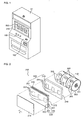
FIG. 1 is a perspective view of a game machine according to an exemplary embodiment of the present invention. -
FIG. 2 is an exploded perspective view of a liquid crystal display and a reel of a game machine according to an exemplary embodiment of the present invention. -
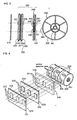
FIG. 3 is a sectional view taken along a line □-□ inFIG. 2 . -
FIG. 4 is a drawing for explaining position relation of a pair of light guide plates and a light switch plate of a back light unit of a liquid crystal display and a symbol selection area of a reel of a game machine according to an exemplary embodiment of the present invention. -
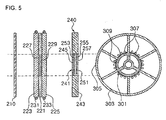
FIG. 5 is a sectional view of a liquid crystal display and a reel of a game machine according to another exemplary embodiment of the present invention. - Embodiments of the present invention will now be described hereinafter with reference to the accompanying drawings.
- In the drawings, the thickness of layers, films, panels, regions, etc. are exaggerated for clarity. Like reference numerals designate like elements throughout the specification. It will be understood that when an element such as a layer, film, region or substrate is referred to as being "on" another element, it can be directly on the other element or intervening elements may also be present. In contrast, when an element is referred to as being "directly on" another element, there are no intervening elements present.
- Since a back light unit according to an embodiment of the present invention and a liquid crystal display including a back light unit according to an embodiment of the present invention are included in a game machine according to an embodiment of the present invention, separate descriptions for a back light unit according to an embodiment of the present invention and a liquid crystal display including a back light unit according to an embodiment of the present invention are omitted.
-
FIG. 1 is a perspective view of a game machine according to an exemplary embodiment of the present invention,FIG. 2 is an exploded perspective view of a liquid crystal display and a reel of a game machine according to an exemplary embodiment of the present invention,FIG. 3 is a sectional view taken along a line □-□ inFIG. 2 ,FIG. 4 is a drawing for explaining position relation of a pair of light guide plates and a light switch plate of a back light unit of a liquid crystal display and a symbol selection area of a reel of a game machine according to an exemplary embodiment of the present invention, andFIG. 5 is a sectional view of a liquid crystal display and a reel of a game machine according to another exemplary embodiment of the present invention. - Referring to
FIG. 1 , a game machine according to an embodiment of the present invention is provided with abody 101 of a cabinet shape, and various parts and controllers for game is housed inbody 101. - Various parts which are necessary for performing game, e.g., an
insert hole 103 for insertion of coin,various input buttons 105 or the like, may be provided or formed tobody 101. - As shown in
FIG. 2 to FIG. 4 , a game machine includes aliquid crystal display 200 which is a display device for displaying images, and areel 300 which is disposed behindliquid crystal display 200. -
Liquid crystal display 200 includes aliquid crystal panel 210 and aback light unit 220. -
Liquid crystal display 200, as shown inFIG. 1 , is installed tobody 101 of a game machine such that a front surface ofliquid crystal panel 210 is exposed to outside. Accordingly,liquid crystal display 200 roles as an image display of a game machine and can display various images such as information or images for performing game and advertisements. -
Liquid crystal display 200 according to an embodiment of the present invention operates to display desired images on the whole image display area ofliquid crystal panel 210 or to convert a predetermined area among the whole image display area to be transparent or translucent. At this time, "transparent" or "translucent" means that an object or image behind the same can be seen in front, and "transparent of translucent" is simply written as "transparent". - The predetermined area is an area corresponding to a symbol selection area where the selected symbol of
reel 300 disposed behindliquid crystal display 200 is disposed, and in case that the predetermined area is turned to be transparent, a symbol (e.g., a figure, a number, a picture or the like) displayed in the symbol selection area ofreel 300 disposed behindliquid crystal display 200 can be seen from the front ofliquid crystal display 200. - In case that
liquid crystal display 200 operates such the predetermined area becomes transparent, a symbol displayed onreel 300 can be seen from the front of a game machine through the predetermined area, so a game using the symbol displayed onreel 300 can be performed. At this time,liquid crystal display 200 operates such that a symbol ofreel 300 can be seen through the predetermined area, and at the same time, may display other information or images necessary for a game or other information or images on an image display area other than the predetermined area. - On the other hand, in case that
liquid crystal display 200 operates such that the predetermined area is not transparent (for example, displaying an image on the whole image display area),liquid crystal display 200 may operate as a normal display device, i.e., operate to display an image on the whole image display area while preventing a symbol of the reel from being seen from the front. - A back light unit, and a liquid crystal display for realizing this function according to an embodiment of the present invention and a game machine including the same will be described in detail hereinafter.
- Referring to
FIG. 2 to FIG. 4 ,liquid crystal display 200 includesliquid crystal panel 210 andback light unit 220 which are disposed back and forth side by side. -
Liquid crystal panel 210 may be a conventional transparent liquid crystal panel, and for example, may be formed by sealing liquid crystal in a space formed between two facing transparent panels such as a glass panel on which thin film transistors are formed. At this time, a basic display mode ofliquid crystal panel 210 may be set as a normally white. "Normally white" means that a white display state (light can penetrate toward a display surface, i.e., light penetrating through a display surface can be from the outside) is realized while a liquid crystal panel is not operated. -
Back light unit 220 acts as a light source ofliquid crystal display 200 and is disposed behindliquid crystal panel 210. - Meanwhile, not shown in the drawing,
liquid crystal display 200 may further include a chassis including various frames and holders for assemblingliquid crystal panel 210 and backlight unit 220. In addition,liquid crystal display 200 may further include well known various parts such as a driving circuit for drivingliquid crystal panel 210, etc. Gap betweenliquid crystal panel 210 and backlight unit 220 is enlarged for ease of description, but both may contact each other and may be disposed with a small gap. - Back
light unit 220 includes a polymer dispersedliquid crystal layer 221 which is formed of polymer dispersed liquid crystal (PDLC). - PDLC is one of liquid crystal cell which can be used in a liquid crystal display (LCD) and regulates penetration of light depending on light scattering intensity. There are some types of PDLC, for example, it may be formed by scattering liquid crystal particles of several µm into polymer, or by containing liquid crystal into net type polymer. Alignment of liquid crystal of PDLC becomes irregular when voltage is not applied thereto and light scattering occurs on a surface having different refractive index from medium, and on the other hand, if voltage is applied to PDLC, directions of liquid crystal molecules becomes uniform so that light can penetrate therethrough.
- Polymer dispersed
liquid crystal layer 221 is formed in a space between a pair oflight guide plates light guide plates liquid crystal layer 221 respectively. - For example, by arranging a pair of
light guide plates light guide plates liquid crystal layer 221 disposed therebetween may be formed. Although structure for sealing polymer dispersedliquid crystal layer 221 is not shown in the drawing, such a structure is obvious to a person in the art, so detailed description for the same will be omitted. -
Light guide plates - At this time, a pattern may not be formed on the surface of
light guide plates light guide plates light guide plates reel 300 can be more brightly seen. - Meanwhile,
transparent electrodes light guide plates transparent electrodes light guide plates liquid crystal layer 221. -
Transparent electrodes - At this time,
transparent electrodes light guide plates liquid crystal layer 221. At this time, the predetermined areas are areas corresponding to a symbol selection area where selected area ofreel 300 disposed behindliquid crystal display 200 is disposed. That is, a plurality of symbols are displayed on an outer surface ofreel 300 and when rotatingreel 300 stops, a symbol which is disposed at the front side ofreel 300 is the selected symbol, andtransparent electrodes reel 300 is disposed, i.e., corresponding to a symbol selection area. At this time,transparent electrodes liquid crystal display 200,transparent electrodes - Meanwhile, not shown in the drawing,
transparent electrodes liquid crystal display 200 may include an electrical circuit for controlling to selectively apply voltage totransparent electrodes -
Light sources light guide plates -
Light source 233 may be realized as an arbitrary device which can emit light such as a cathode ray lamp and LED lamp. For example, as shown in the drawing,light sources light guide plates light sources light guide plate 233 and 235 respectively, light source may be disposed at only one of the upper edge and the lower edge of the light guide plate and may be disposed at least one of a left edge or a right edge of the light guide plate. - Polymer dispersed
liquid crystal layer 221 which is formed betweenlight guide plates light source module 230 to make more uniform. Since light is diffused by polymer dispersedliquid crystal layer 221 and then goes forward, luminance becomes more uniform and view angle becomes greater. - Meanwhile, according to another embodiment of the present invention, a
light switch plate 240 which is interposed betweenlight source module 230 and reel 300 may be further provided. - A predetermined area of
light switch plate 240 may be formed to be selectively converted to a light penetration area, and the remained area thereof is made of non-transparent material. - At this time, the predetermined area of
light switch plate 240 is an area corresponding to an area occupied bytransparent electrodes light guide plates - As shown in the drawing,
light switch plate 240 may include alight switch member 241 which is disposed at an area corresponding to an area oftransparent electrodes non-transparent portion 243 occupying the remained area. - Accordingly, seeing from the front of
liquid crystal display 200,transparent electrodes light guide plates light switch member 241 disposed at the predetermined area oflight switch plate 240, and the symbol selection area ofreel 300 are overlapped in a back and forth direction. -
Light switch member 241 may be realized as a device which can be selectively converted into one of a transparent state a non-transparent state, and for example, may be realized as a liquid crystal panel including a liquid crystal layer which can be selectively converted from a non-transparent state to a transparent state. In particular,light switch member 241 may be realized as a TN liquid crystal panel including TN liquid crystal layer which is made of liquid crystal operating in a TN(Twisted Nematic) type. Since TN type has a low optical penetration ratio,light switch member 241 made of TN liquid crystal panel can effectively hide in a non-transparent state thereel 300 behind. Hereinafter, a case thatlight switch member 241 is TN liquid crystal panel is exemplarily described. - For example, TN
liquid crystal panel 241 may includetransparent plates TN liquid layer 251 which is formed in a space betweentransparent plates transparent electrodes transparent plates liquid crystal layer 251. - For example,
transparent plates liquid crystal layer 251 may be formed by sealing liquid crystal in a space betweentransparent plates -
Transparent electrodes -
Non-transparent portion 243 oflight switch plate 240 may be arbitrary non-transparent material such as non-transparent synthetic resin. - For example, by applying voltage to
transparent electrodes liquid crystal layer 251 so as to convertTN liquid layer 251 into a transparent state, TNliquid crystal panel 241 can become a transparent state having light penetration characteristic. In this way, TNliquid crystal panel 241 can selectively become a transparent state, so TNliquid crystal panel 241 can act as a light switch. -
Reel 300 is housed withinbody 101 of a game machine so as to be disposed behindliquid crystal display 200.Reel 300 may be provided as a plural,respective reel 300 may be disposed adjacently in parallel.Respective reel 300 may be formed to rotate independently. - For example, reel 300 may include a
reel drum 301 and areel strip 303 which is attached to an outer surface ofreel drum 301. And a motor (not shown) for rotatingreel drum 301 may be provided. - For example,
reel strip 303 may be made of translucent resin. - A plurality of
symbols 305 may be displayed on an outer surface ofreel strip 303, andrespective symbol 305 may be equidistantly disposed with some interval therebetween. At this time, the symbol may be a number, a picture, a letter, etc. Hereinafter, an area ofreel strip 303 where the symbol is displayed is referred to as a symbol display area. That is,respective reel 300 has symbol display area of the same number with the number ofsymbols 305 displayed on an outer surface thereof. -
Respective reel 300 may rotate and stop at a state that the symbol display area where the symbol is displayed is positioned at a front center. Hereinafter, an imaginary area corresponding to a front center at which the symbol display area where thesymbol 305 is displayed stops is referred to as the symbol selection area. - As shown in
FIG. 3 and FIG. 4 , an area occupied bytransparent electrodes light guide plates light switch member 241 oflight switch plate 240, i.e., TNliquid crystal panel 241 are disposed at a position corresponding to the symbol selection area. - That is, a number, a position, a size, and a shape of
transparent electrodes light guide plates liquid crystal panel 241 oflight switch plate 240 corresponds to a number, a position, a size, and a shape of the symbol selection area ofreel 300. For example, as shown in the drawing, threereels 300 are arranged in a horizontal direction,transparent electrodes liquid crystal panel 241 are provided as three respectively, and have a position and a shape corresponding to a position and a shape of the symbol selection area. - If voltage is applied to
transparent electrodes liquid crystal layer 221 which is interposed betweentransparent electrodes reel 300 behindtransparent electrodes liquid crystal display 200. - At this time, a portion of
liquid crystal panel 210 corresponding to an area wheretransparent electrodes reel 300 can be seen from the front ofliquid crystal display 200 through an area wheretransparent electrodes light unit 220 are positioned and the corresponding area ofliquid crystal panel 210. - In addition, in case that
light switch plate 240 is further provided, so as to make polymer dispersedliquid crystal layer 221 and TNliquid crystal layer 241 which correspond to the symbol selection area ofreel 300 transparent respectively, voltage is respectively applied totransparent electrodes liquid crystal layer 221 andtransparent electrodes liquid crystal layer 251, and thereby the selected symbol positioned at the symbol selection area ofreel 300 can be seen from the front of a game machine. - A game machine according to another embodiment of the present invention will be described with reference to
FIG. 5 . - According to another embodiment of the present invention, an auxiliary
light source 307 is disposed behind the symbol display area wheresymbol 305 ofreel 300 is displayed. For example, referringFIG. 5 , auxiliarylight source 307 may be mounted on amount 309 which is disposed behind the symbol display area wheresymbol 305 is displayed. Auxiliarylight source 307 may be an arbitrary light source emitting light such as an LED lamp. - In this case, by applying voltage to
transparent electrodes transparent electrodes symbol 305 ofreel 300 can be from the front of a game machine. In particular, at this time, by turning onlight source 307 disposed behind the symbol display area ofreel 300, the symbol displayed on the selected symbol display area can be further brightly seen. - The present invention relates to a back light unit, and a liquid crystal display and a game machine including the same, so has an industrial applicability.
| 200: | liquid crystal display | 210: | liquid crystal panel |
| 220: | back light unit | 221: | polymer dispersed |
| 223, 225: | |
231, 233: | light source |
| 300: | reel | 301: | reel drum |
| 303: | reel strip | 305: | symbol |
| 307: | auxiliary light source |
Claims (6)
- A back light unit (220) for a liquid crystal display (200) comprising:a pair of light guide plates (223, 225) which are disposed to face each other, transparent electrodes (227, 229) being formed on corresponding predetermined areas of surfaces facing each other of the light guide plates (223, 225);a polymer dispersed liquid crystal layer (221) which is formed in a space between the light guide plates (223, 225) and is formed by polymer dispersed liquid crystal;a plurality of light sources (231, 233) respectively disposed at edges of the light guide plates (223, 225); anda light switch plate (240) which is disposed, in a first direction, behind the light guide plates (223, 225) and which comprises a light switch member (241) which can be selectively converted into a transparent state and areas (243) made of nontransparent material, characterized in that the light switch member (241) is disposed at an area of the light switch plate (240) corresponding to the predetermined areas of the light guide plate (223, 225), and the remaining areas (243) of the light switch plate (240) form said areas (243) of nontransparent material.
- The back light unit (220) of claim 1, wherein no pattern is provided on the surfaces of the light guide plates (223, 225).
- The back light unit (220) of claim 1, wherein the light switch member (241) is a TN liquid crystal panel which can be selectively converted into a transparent state.
- A liquid crystal display (200) comprising:a back light unit (220) of one of claim 1 to claim 3; anda liquid crystal panel (210) disposed, in the first direction, in front of the pair of the light guide plates (223, 225) of the back light unit (220).
- A game machine comprising:a liquid crystal display (200) including a liquid crystal panel (210) and a back light unit (220) of one of claim 1 to claim 3, the back light unit (220) being disposed behind the liquid crystal panel (210); andat least one reel (300) which is disposed, in the first direction, behind the back light unit (220) and on which a plurality of symbols (305) are disposed.
- The game machine of claim 5, further comprising an auxiliary light source (307) disposed, in the first direction, behind an area of the reel (300) where a symbol (305) is displayed.
Priority Applications (1)
| Application Number | Priority Date | Filing Date | Title |
|---|---|---|---|
| SI200931002T SI2296033T1 (en) | 2008-06-09 | 2009-06-08 | Backlight unit, and liquid crystal display and gaming machine comprising the same |
Applications Claiming Priority (2)
| Application Number | Priority Date | Filing Date | Title |
|---|---|---|---|
| KR1020080053586A KR100961903B1 (en) | 2008-06-09 | 2008-06-09 | Backlight unit and liquid crystal display device and game machine with the same |
| PCT/KR2009/003058 WO2009151244A2 (en) | 2008-06-09 | 2009-06-08 | Backlight unit, and liquid crystal display and gaming machine comprising the same |
Publications (3)
| Publication Number | Publication Date |
|---|---|
| EP2296033A2 EP2296033A2 (en) | 2011-03-16 |
| EP2296033A4 EP2296033A4 (en) | 2011-10-26 |
| EP2296033B1 true EP2296033B1 (en) | 2014-06-18 |
Family
ID=41417224
Family Applications (1)
| Application Number | Title | Priority Date | Filing Date |
|---|---|---|---|
| EP09762631.1A Active EP2296033B1 (en) | 2008-06-09 | 2009-06-08 | Backlight unit, and liquid crystal display and gaming machine comprising the same |
Country Status (7)
| Country | Link |
|---|---|
| US (1) | US8390762B2 (en) |
| EP (1) | EP2296033B1 (en) |
| JP (1) | JP5390602B2 (en) |
| KR (1) | KR100961903B1 (en) |
| ES (1) | ES2499398T3 (en) |
| SI (1) | SI2296033T1 (en) |
| WO (1) | WO2009151244A2 (en) |
Families Citing this family (14)
| Publication number | Priority date | Publication date | Assignee | Title |
|---|---|---|---|---|
| KR101153892B1 (en) * | 2010-07-06 | 2012-06-05 | (주)코텍 | Display device with sub backlight |
| KR101314267B1 (en) * | 2011-10-14 | 2013-10-02 | 주식회사 토비스 | Display device and game machine including the same |
| KR101333771B1 (en) * | 2011-11-14 | 2013-11-29 | 주식회사 토비스 | Backlight unit and liquid crystal display device and game machine with the same |
| US9082256B2 (en) * | 2012-04-17 | 2015-07-14 | Igt | Backlight for video display |
| JP2013220263A (en) * | 2012-04-18 | 2013-10-28 | Omron Corp | Inter-machine dispenser for game machine, game machine, and game system |
| JP2013220264A (en) * | 2012-04-18 | 2013-10-28 | Omron Corp | Game machine display device |
| US20150338715A1 (en) * | 2012-07-09 | 2015-11-26 | Red Bull Gmbh | Transparent display device |
| KR101417747B1 (en) | 2012-09-20 | 2014-07-10 | 주식회사 토비스 | Backlight unit and liquid crystal display device and game machine with the same |
| KR101540291B1 (en) * | 2014-07-11 | 2015-07-31 | 주식회사 지티티 | Curved LCD apparatus |
| JP2016224199A (en) * | 2015-05-28 | 2016-12-28 | 株式会社大一商会 | Image display device |
| JP2017032635A (en) * | 2015-07-29 | 2017-02-09 | 株式会社大一商会 | Image display system |
| JP7281329B2 (en) * | 2019-04-16 | 2023-05-25 | 株式会社ジャパンディスプレイ | Display device |
| KR102224652B1 (en) * | 2019-08-02 | 2021-03-08 | 주식회사 토비스 | Transparent display device by rotating afterimage and game machine with the same |
| JP2023023545A (en) * | 2021-08-05 | 2023-02-16 | オムロン株式会社 | Operation unit and game machine |
Family Cites Families (13)
| Publication number | Priority date | Publication date | Assignee | Title |
|---|---|---|---|---|
| US5099343A (en) * | 1989-05-25 | 1992-03-24 | Hughes Aircraft Company | Edge-illuminated liquid crystal display devices |
| US6166789A (en) * | 1994-07-21 | 2000-12-26 | Ncr Corporation | Liquid crystal display |
| JPH09330609A (en) * | 1995-12-05 | 1997-12-22 | Matsushita Electric Ind Co Ltd | Back-light device and color display device |
| FR2743924B1 (en) * | 1996-01-23 | 1998-05-22 | Asulab Sa | DEVICE FOR DISPLAYING A DECOR AND WATCHMAKING PART COMPRISING SAME |
| DE10034484A1 (en) * | 2000-07-15 | 2002-01-31 | Bosch Gmbh Robert | Illumination device e.g. for motor vehicle has electro-optical elements individually controlled to control light distribution |
| JP3900805B2 (en) | 2000-08-03 | 2007-04-04 | 株式会社日立製作所 | LIGHTING DEVICE AND LIQUID CRYSTAL DISPLAY DEVICE USING THE SAME |
| JP2004166964A (en) * | 2002-11-20 | 2004-06-17 | Aruze Corp | Game machine |
| KR100518408B1 (en) * | 2003-08-22 | 2005-09-29 | 엘지.필립스 엘시디 주식회사 | Dual liquid crystal display using of dual front light |
| GB0326005D0 (en) | 2003-11-07 | 2003-12-10 | Koninkl Philips Electronics Nv | Waveguide for autostereoscopic display |
| JP2005266387A (en) | 2004-03-19 | 2005-09-29 | Sanyo Electric Co Ltd | See-through type liquid crystal module and see-through type liquid crystal display device |
| KR20060035331A (en) * | 2004-10-22 | 2006-04-26 | 삼성전자주식회사 | Display apparatus |
| JP2007215983A (en) * | 2006-01-19 | 2007-08-30 | Active Inc | Liquid crystal shutter device for game machine |
| KR100858868B1 (en) * | 2006-11-07 | 2008-09-17 | 주식회사 토비스 | A slot machine-reel game conversion type picture on the screen display panel reflect structure |
-
2008
- 2008-06-09 KR KR1020080053586A patent/KR100961903B1/en active IP Right Grant
-
2009
- 2009-06-08 SI SI200931002T patent/SI2296033T1/en unknown
- 2009-06-08 EP EP09762631.1A patent/EP2296033B1/en active Active
- 2009-06-08 WO PCT/KR2009/003058 patent/WO2009151244A2/en active Application Filing
- 2009-06-08 ES ES09762631.1T patent/ES2499398T3/en active Active
- 2009-06-08 US US12/996,976 patent/US8390762B2/en active Active
- 2009-06-08 JP JP2011512390A patent/JP5390602B2/en active Active
Also Published As
| Publication number | Publication date |
|---|---|
| WO2009151244A2 (en) | 2009-12-17 |
| US8390762B2 (en) | 2013-03-05 |
| JP5390602B2 (en) | 2014-01-15 |
| JP2011523094A (en) | 2011-08-04 |
| ES2499398T3 (en) | 2014-09-29 |
| WO2009151244A3 (en) | 2010-03-11 |
| EP2296033A4 (en) | 2011-10-26 |
| EP2296033A2 (en) | 2011-03-16 |
| KR100961903B1 (en) | 2010-06-10 |
| SI2296033T1 (en) | 2014-09-30 |
| US20110085109A1 (en) | 2011-04-14 |
| KR20090127547A (en) | 2009-12-14 |
Similar Documents
| Publication | Publication Date | Title |
|---|---|---|
| EP2296033B1 (en) | Backlight unit, and liquid crystal display and gaming machine comprising the same | |
| US8847849B2 (en) | Display apparatus | |
| EP3479168B1 (en) | Viewing angle control device and display apparatus | |
| US8467014B2 (en) | Back light unit and liquid crystal display device and game machine including the same | |
| US8711059B2 (en) | Display apparatus | |
| KR101357185B1 (en) | Partially transparent display apparatus | |
| JP5160635B2 (en) | Liquid crystal display unit, liquid crystal display unit control method, and game apparatus | |
| JP2014532200A (en) | Display device and game machine including the same | |
| JP2007127940A (en) | Liquid crystal display device | |
| AU2012299609B2 (en) | Backlight unit and liquid crystal display device and gaming machine including same | |
| US7733438B2 (en) | Liquid crystal display device | |
| AU2012337590B2 (en) | Backlight unit, and liquid crystal display device and game console including same | |
| JP2006098550A (en) | Liquid crystal display |
Legal Events
| Date | Code | Title | Description |
|---|---|---|---|
| PUAI | Public reference made under article 153(3) epc to a published international application that has entered the european phase |
Free format text: ORIGINAL CODE: 0009012 |
|
| 17P | Request for examination filed |
Effective date: 20101217 |
|
| AK | Designated contracting states |
Kind code of ref document: A2 Designated state(s): AT BE BG CH CY CZ DE DK EE ES FI FR GB GR HR HU IE IS IT LI LT LU LV MC MK MT NL NO PL PT RO SE SI SK TR |
|
| AX | Request for extension of the european patent |
Extension state: AL BA RS |
|
| DAX | Request for extension of the european patent (deleted) | ||
| A4 | Supplementary search report drawn up and despatched |
Effective date: 20110922 |
|
| RIC1 | Information provided on ipc code assigned before grant |
Ipc: G02F 1/1347 20060101ALI20110916BHEP Ipc: A63F 13/00 20060101ALI20110916BHEP Ipc: G07F 17/32 20060101ALI20110916BHEP Ipc: G02F 1/13357 20060101AFI20110916BHEP |
|
| GRAP | Despatch of communication of intention to grant a patent |
Free format text: ORIGINAL CODE: EPIDOSNIGR1 |
|
| INTG | Intention to grant announced |
Effective date: 20140109 |
|
| GRAS | Grant fee paid |
Free format text: ORIGINAL CODE: EPIDOSNIGR3 |
|
| GRAA | (expected) grant |
Free format text: ORIGINAL CODE: 0009210 |
|
| AK | Designated contracting states |
Kind code of ref document: B1 Designated state(s): AT BE BG CH CY CZ DE DK EE ES FI FR GB GR HR HU IE IS IT LI LT LU LV MC MK MT NL NO PL PT RO SE SI SK TR |
|
| REG | Reference to a national code |
Ref country code: GB Ref legal event code: FG4D |
|
| REG | Reference to a national code |
Ref country code: CH Ref legal event code: EP |
|
| REG | Reference to a national code |
Ref country code: AT Ref legal event code: REF Ref document number: 673662 Country of ref document: AT Kind code of ref document: T Effective date: 20140715 |
|
| REG | Reference to a national code |
Ref country code: IE Ref legal event code: FG4D |
|
| REG | Reference to a national code |
Ref country code: DE Ref legal event code: R096 Ref document number: 602009024773 Country of ref document: DE Effective date: 20140731 |
|
| REG | Reference to a national code |
Ref country code: ES Ref legal event code: FG2A Ref document number: 2499398 Country of ref document: ES Kind code of ref document: T3 Effective date: 20140929 |
|
| PG25 | Lapsed in a contracting state [announced via postgrant information from national office to epo] |
Ref country code: LT Free format text: LAPSE BECAUSE OF FAILURE TO SUBMIT A TRANSLATION OF THE DESCRIPTION OR TO PAY THE FEE WITHIN THE PRESCRIBED TIME-LIMIT Effective date: 20140618 Ref country code: CY Free format text: LAPSE BECAUSE OF FAILURE TO SUBMIT A TRANSLATION OF THE DESCRIPTION OR TO PAY THE FEE WITHIN THE PRESCRIBED TIME-LIMIT Effective date: 20140618 Ref country code: FI Free format text: LAPSE BECAUSE OF FAILURE TO SUBMIT A TRANSLATION OF THE DESCRIPTION OR TO PAY THE FEE WITHIN THE PRESCRIBED TIME-LIMIT Effective date: 20140618 Ref country code: NO Free format text: LAPSE BECAUSE OF FAILURE TO SUBMIT A TRANSLATION OF THE DESCRIPTION OR TO PAY THE FEE WITHIN THE PRESCRIBED TIME-LIMIT Effective date: 20140918 Ref country code: GR Free format text: LAPSE BECAUSE OF FAILURE TO SUBMIT A TRANSLATION OF THE DESCRIPTION OR TO PAY THE FEE WITHIN THE PRESCRIBED TIME-LIMIT Effective date: 20140919 |
|
| REG | Reference to a national code |
Ref country code: NL Ref legal event code: VDEP Effective date: 20140618 |
|
| REG | Reference to a national code |
Ref country code: LT Ref legal event code: MG4D |
|
| PG25 | Lapsed in a contracting state [announced via postgrant information from national office to epo] |
Ref country code: HR Free format text: LAPSE BECAUSE OF FAILURE TO SUBMIT A TRANSLATION OF THE DESCRIPTION OR TO PAY THE FEE WITHIN THE PRESCRIBED TIME-LIMIT Effective date: 20140618 Ref country code: SE Free format text: LAPSE BECAUSE OF FAILURE TO SUBMIT A TRANSLATION OF THE DESCRIPTION OR TO PAY THE FEE WITHIN THE PRESCRIBED TIME-LIMIT Effective date: 20140618 Ref country code: LV Free format text: LAPSE BECAUSE OF FAILURE TO SUBMIT A TRANSLATION OF THE DESCRIPTION OR TO PAY THE FEE WITHIN THE PRESCRIBED TIME-LIMIT Effective date: 20140618 |
|
| PG25 | Lapsed in a contracting state [announced via postgrant information from national office to epo] |
Ref country code: EE Free format text: LAPSE BECAUSE OF FAILURE TO SUBMIT A TRANSLATION OF THE DESCRIPTION OR TO PAY THE FEE WITHIN THE PRESCRIBED TIME-LIMIT Effective date: 20140618 Ref country code: RO Free format text: LAPSE BECAUSE OF FAILURE TO SUBMIT A TRANSLATION OF THE DESCRIPTION OR TO PAY THE FEE WITHIN THE PRESCRIBED TIME-LIMIT Effective date: 20140618 Ref country code: CZ Free format text: LAPSE BECAUSE OF FAILURE TO SUBMIT A TRANSLATION OF THE DESCRIPTION OR TO PAY THE FEE WITHIN THE PRESCRIBED TIME-LIMIT Effective date: 20140618 Ref country code: SK Free format text: LAPSE BECAUSE OF FAILURE TO SUBMIT A TRANSLATION OF THE DESCRIPTION OR TO PAY THE FEE WITHIN THE PRESCRIBED TIME-LIMIT Effective date: 20140618 Ref country code: PT Free format text: LAPSE BECAUSE OF FAILURE TO SUBMIT A TRANSLATION OF THE DESCRIPTION OR TO PAY THE FEE WITHIN THE PRESCRIBED TIME-LIMIT Effective date: 20141020 |
|
| PG25 | Lapsed in a contracting state [announced via postgrant information from national office to epo] |
Ref country code: IS Free format text: LAPSE BECAUSE OF FAILURE TO SUBMIT A TRANSLATION OF THE DESCRIPTION OR TO PAY THE FEE WITHIN THE PRESCRIBED TIME-LIMIT Effective date: 20141018 Ref country code: PL Free format text: LAPSE BECAUSE OF FAILURE TO SUBMIT A TRANSLATION OF THE DESCRIPTION OR TO PAY THE FEE WITHIN THE PRESCRIBED TIME-LIMIT Effective date: 20140618 Ref country code: NL Free format text: LAPSE BECAUSE OF FAILURE TO SUBMIT A TRANSLATION OF THE DESCRIPTION OR TO PAY THE FEE WITHIN THE PRESCRIBED TIME-LIMIT Effective date: 20140618 |
|
| REG | Reference to a national code |
Ref country code: DE Ref legal event code: R097 Ref document number: 602009024773 Country of ref document: DE |
|
| PLBE | No opposition filed within time limit |
Free format text: ORIGINAL CODE: 0009261 |
|
| STAA | Information on the status of an ep patent application or granted ep patent |
Free format text: STATUS: NO OPPOSITION FILED WITHIN TIME LIMIT |
|
| PG25 | Lapsed in a contracting state [announced via postgrant information from national office to epo] |
Ref country code: DK Free format text: LAPSE BECAUSE OF FAILURE TO SUBMIT A TRANSLATION OF THE DESCRIPTION OR TO PAY THE FEE WITHIN THE PRESCRIBED TIME-LIMIT Effective date: 20140618 Ref country code: IT Free format text: LAPSE BECAUSE OF FAILURE TO SUBMIT A TRANSLATION OF THE DESCRIPTION OR TO PAY THE FEE WITHIN THE PRESCRIBED TIME-LIMIT Effective date: 20140618 |
|
| 26N | No opposition filed |
Effective date: 20150319 |
|
| PG25 | Lapsed in a contracting state [announced via postgrant information from national office to epo] |
Ref country code: BE Free format text: LAPSE BECAUSE OF FAILURE TO SUBMIT A TRANSLATION OF THE DESCRIPTION OR TO PAY THE FEE WITHIN THE PRESCRIBED TIME-LIMIT Effective date: 20140618 |
|
| REG | Reference to a national code |
Ref country code: DE Ref legal event code: R097 Ref document number: 602009024773 Country of ref document: DE Effective date: 20150319 |
|
| PGFP | Annual fee paid to national office [announced via postgrant information from national office to epo] |
Ref country code: ES Payment date: 20150616 Year of fee payment: 7 Ref country code: SI Payment date: 20150608 Year of fee payment: 7 |
|
| PGFP | Annual fee paid to national office [announced via postgrant information from national office to epo] |
Ref country code: AT Payment date: 20150629 Year of fee payment: 7 |
|
| PG25 | Lapsed in a contracting state [announced via postgrant information from national office to epo] |
Ref country code: MC Free format text: LAPSE BECAUSE OF FAILURE TO SUBMIT A TRANSLATION OF THE DESCRIPTION OR TO PAY THE FEE WITHIN THE PRESCRIBED TIME-LIMIT Effective date: 20140618 |
|
| REG | Reference to a national code |
Ref country code: CH Ref legal event code: PL |
|
| PG25 | Lapsed in a contracting state [announced via postgrant information from national office to epo] |
Ref country code: LU Free format text: LAPSE BECAUSE OF FAILURE TO SUBMIT A TRANSLATION OF THE DESCRIPTION OR TO PAY THE FEE WITHIN THE PRESCRIBED TIME-LIMIT Effective date: 20150608 |
|
| REG | Reference to a national code |
Ref country code: IE Ref legal event code: MM4A |
|
| REG | Reference to a national code |
Ref country code: FR Ref legal event code: ST Effective date: 20160229 |
|
| PG25 | Lapsed in a contracting state [announced via postgrant information from national office to epo] |
Ref country code: CH Free format text: LAPSE BECAUSE OF NON-PAYMENT OF DUE FEES Effective date: 20150630 Ref country code: LI Free format text: LAPSE BECAUSE OF NON-PAYMENT OF DUE FEES Effective date: 20150630 Ref country code: IE Free format text: LAPSE BECAUSE OF NON-PAYMENT OF DUE FEES Effective date: 20150608 |
|
| PG25 | Lapsed in a contracting state [announced via postgrant information from national office to epo] |
Ref country code: FR Free format text: LAPSE BECAUSE OF NON-PAYMENT OF DUE FEES Effective date: 20150630 |
|
| PG25 | Lapsed in a contracting state [announced via postgrant information from national office to epo] |
Ref country code: MT Free format text: LAPSE BECAUSE OF FAILURE TO SUBMIT A TRANSLATION OF THE DESCRIPTION OR TO PAY THE FEE WITHIN THE PRESCRIBED TIME-LIMIT Effective date: 20140618 |
|
| REG | Reference to a national code |
Ref country code: AT Ref legal event code: MM01 Ref document number: 673662 Country of ref document: AT Kind code of ref document: T Effective date: 20160608 |
|
| REG | Reference to a national code |
Ref country code: SI Ref legal event code: KO00 Effective date: 20170228 |
|
| PG25 | Lapsed in a contracting state [announced via postgrant information from national office to epo] |
Ref country code: HU Free format text: LAPSE BECAUSE OF FAILURE TO SUBMIT A TRANSLATION OF THE DESCRIPTION OR TO PAY THE FEE WITHIN THE PRESCRIBED TIME-LIMIT; INVALID AB INITIO Effective date: 20090608 Ref country code: AT Free format text: LAPSE BECAUSE OF NON-PAYMENT OF DUE FEES Effective date: 20160608 Ref country code: SI Free format text: LAPSE BECAUSE OF NON-PAYMENT OF DUE FEES Effective date: 20160609 |
|
| PG25 | Lapsed in a contracting state [announced via postgrant information from national office to epo] |
Ref country code: BG Free format text: THE PATENT HAS BEEN ANNULLED BY A DECISION OF A NATIONAL AUTHORITY Effective date: 20150630 |
|
| PG25 | Lapsed in a contracting state [announced via postgrant information from national office to epo] |
Ref country code: TR Free format text: LAPSE BECAUSE OF FAILURE TO SUBMIT A TRANSLATION OF THE DESCRIPTION OR TO PAY THE FEE WITHIN THE PRESCRIBED TIME-LIMIT Effective date: 20140618 |
|
| PG25 | Lapsed in a contracting state [announced via postgrant information from national office to epo] |
Ref country code: ES Free format text: LAPSE BECAUSE OF NON-PAYMENT OF DUE FEES Effective date: 20160609 |
|
| PG25 | Lapsed in a contracting state [announced via postgrant information from national office to epo] |
Ref country code: MK Free format text: LAPSE BECAUSE OF FAILURE TO SUBMIT A TRANSLATION OF THE DESCRIPTION OR TO PAY THE FEE WITHIN THE PRESCRIBED TIME-LIMIT Effective date: 20140618 |
|
| REG | Reference to a national code |
Ref country code: ES Ref legal event code: FD2A Effective date: 20181127 |
|
| PGFP | Annual fee paid to national office [announced via postgrant information from national office to epo] |
Ref country code: DE Payment date: 20230412 Year of fee payment: 15 |
|
| PGFP | Annual fee paid to national office [announced via postgrant information from national office to epo] |
Ref country code: GB Payment date: 20230420 Year of fee payment: 15 |