EP2295904A2 - Appareil de refroidissement doté d'un support de produit réfrigéré - Google Patents
Appareil de refroidissement doté d'un support de produit réfrigéré Download PDFInfo
- Publication number
- EP2295904A2 EP2295904A2 EP10172875A EP10172875A EP2295904A2 EP 2295904 A2 EP2295904 A2 EP 2295904A2 EP 10172875 A EP10172875 A EP 10172875A EP 10172875 A EP10172875 A EP 10172875A EP 2295904 A2 EP2295904 A2 EP 2295904A2
- Authority
- EP
- European Patent Office
- Prior art keywords
- refrigerating appliance
- appliance according
- strips
- refrigerated goods
- carrier
- Prior art date
- Legal status (The legal status is an assumption and is not a legal conclusion. Google has not performed a legal analysis and makes no representation as to the accuracy of the status listed.)
- Withdrawn
Links
Images


Classifications
-
- F—MECHANICAL ENGINEERING; LIGHTING; HEATING; WEAPONS; BLASTING
- F25—REFRIGERATION OR COOLING; COMBINED HEATING AND REFRIGERATION SYSTEMS; HEAT PUMP SYSTEMS; MANUFACTURE OR STORAGE OF ICE; LIQUEFACTION SOLIDIFICATION OF GASES
- F25D—REFRIGERATORS; COLD ROOMS; ICE-BOXES; COOLING OR FREEZING APPARATUS NOT OTHERWISE PROVIDED FOR
- F25D25/00—Charging, supporting, and discharging the articles to be cooled
- F25D25/02—Charging, supporting, and discharging the articles to be cooled by shelves
-
- F—MECHANICAL ENGINEERING; LIGHTING; HEATING; WEAPONS; BLASTING
- F25—REFRIGERATION OR COOLING; COMBINED HEATING AND REFRIGERATION SYSTEMS; HEAT PUMP SYSTEMS; MANUFACTURE OR STORAGE OF ICE; LIQUEFACTION SOLIDIFICATION OF GASES
- F25D—REFRIGERATORS; COLD ROOMS; ICE-BOXES; COOLING OR FREEZING APPARATUS NOT OTHERWISE PROVIDED FOR
- F25D23/00—General constructional features
- F25D23/06—Walls
- F25D23/065—Details
- F25D23/067—Supporting elements
-
- F—MECHANICAL ENGINEERING; LIGHTING; HEATING; WEAPONS; BLASTING
- F25—REFRIGERATION OR COOLING; COMBINED HEATING AND REFRIGERATION SYSTEMS; HEAT PUMP SYSTEMS; MANUFACTURE OR STORAGE OF ICE; LIQUEFACTION SOLIDIFICATION OF GASES
- F25D—REFRIGERATORS; COLD ROOMS; ICE-BOXES; COOLING OR FREEZING APPARATUS NOT OTHERWISE PROVIDED FOR
- F25D2325/00—Charging, supporting or discharging the articles to be cooled, not provided for in other groups of this subclass
- F25D2325/022—Shelves made of glass or ceramic
Definitions
- the present invention relates to a refrigeration appliance, in particular a domestic refrigeration appliance, with a storage chamber in which one or more refrigerated goods carriers are mounted.
- the storage chamber of a refrigerator is limited by a deep-drawn inner container.
- the technique of deep drawing implies that opposite side walls of the inner container are not exactly parallel, but slightly diverge toward a front of the device.
- the shape of the refrigerated goods carriers must take account of this non-parallelism, the so-called draft angle.
- a refrigerated goods carrier, which rests on the supports, can be rotated so that one of its lateral edges runs parallel to a side wall of the inner container and the divergence between the other lateral edge and the side wall opposite it is greater.
- the refrigerated goods carrier is only safely supported if rest in any reachable position, the lateral edges of so far apart points of the pads that the center of gravity of the refrigerated goods carrier can not get overweight. For this purpose, a large width of the pads is required. However, the wider the conditions are, the smaller is the usable volume of the refrigeration device given the external dimensions.
- Object of the present invention is to provide a refrigeration device, in which a secure support adegutabstellers is possible even with slight overlap with the requirements of the side walls.
- the object is achieved by providing in a refrigeration device with an inner container having diverging side walls to a front side, and at least onedegutabsteller resting on supports formed on each side wall, at least a front portion of the pads stop surfaces of the refrigerated goods in the transverse direction of the Inner container are opposite, the refrigerated goods to the conditions, eg be positioned as support ribs, position so that the refrigerated goods carrier front rests securely on the front areas of the supports ..
- These abutment surfaces limit the freedom of rotation of the refrigerated goods, so that the width is reduced, which must have the conditions to the refrigerated goods in each Orientation that this can take to support.
- a rear area of the pads also faces abutment surfaces in the transverse direction in order to minimize the freedom of rotation of the latter for a given dimensional tolerance of the inner container and the refrigerated goods carrier.
- stop surfaces on opposite sides of thebisgutabstellers have the same divergence as the side walls
- the pads may be in a conventional manner lower walls of recessed in the side walls horizontal grooves; Preferably, they are formed by attached to the side walls front and rear support cam, each of the front support cam can form the above-mentioned front portion of the pads and the rear support cam the rear area.
- the carrier cams engage in downwardly and to the side open recesses of the strips and are thus largely hidden from the eyes of a user, even if the plate consists of a transparent material, in particular a safety glass.
- the abutment surfaces then expediently form an inner surface of one of the recesses.
- At least one of the recesses has an undercut, which engages in one of the carrier cam.
- the refrigerated goods can not easily stand out from the carrier cam when it is overloaded in an opposite to this carrier cam edge region.
- the undercut preferably faces a front edge of the refrigerated goods carrier, so that a user who wishes to remove the refrigerated goods carrier can do so in an intuitively obvious manner by raising and pulling forward.
- the front and rear cams are preferably of the same shape. This implies that they each protrude equally far beyond the side walls, and that the distance between facing end faces of two rear cams due to the Entformungsschräge is smaller than the distance between the end faces of two front cams.
- the strips can diverge as the side walls of the inner container to the front of the refrigerator.
- the distance of the front and rear abutment surfaces from the lateral edge of the bar can be the same.
- the strips each comprise a profile element to which the plate is fastened, and at least one adapter part attached to the profile element, on which the stop surfaces are formed.
- the profile element can be obtained in a simple manner by cutting an extruded profile in the required length with minor reworking; Contours that are not compatible with the production by extrusion, such as in particular the stop surfaces are reserved for the adapter part.
- the adapter part can be expediently inserted into a cavity of the profile element.
- the adapter part may be formed on this an elastically deflectable latching projection which engages in a latching recess of the hollow profile.
- Fig. 1 shows a schematic horizontal section through the housing of a household refrigerator with a body 31 and a door 32, which enclose a storage chamber 33.
- the body 31 is constructed in a manner known per se from a plastic container deep-drawn inner container 34, outer wall plates 35 and insulating material 36, which fills a gap between the inner container 34 and the outer wall panels 35.
- the inner container 34 has forward, towards the door 32 towards diverging side walls 37.
- the divergence or Entformungsschräge the side walls 37 is in the FIG. 1 for the sake of clarity exaggerated.
- a refrigerated goods carrier 38 can be seen in plan view. It comprises a rectangular glass plate 1 and on the side edges 2 of the glass plate 1 plugged, the edges 2 firmly clamped or glued to them strips 3.
- the strips 3 rest on support cam 9, which are inserted and anchored in attracted in the side walls 37 wells 40.
- the free ends of the carrier cam 9 engage in down and to the respective opposite side walls 37 toward open recesses 8a, 8b of the strips 3 a.
- the carrier cams 9 are all identical, but the distance between the side wall 37 and the opposite edge of the strip 3 at the level of the front support cam 9 is greater than at the level of the rear, the front recesses 8b extend less far into the strips 3 inside as the rear recesses 8a, so that when the refrigerated goods carrier 38 as in the Fig. 1 is shown centered and symmetrically placed, the distance between the side walls 37 facing away from end faces of the carrier cam 39 and their opposite stop surfaces 41 at all recesses 8a, 8b in the context of the dimensional accuracy of the inner container 34 is the same.
- the overlap a between the carrier cam 9 and the strips 3 at the level of the front recesses 8b may be smaller than the distance b between the outer flanks 42 of the strips 3 and the opposite side wall 37 without rotation of the Refrigerated goods carrier 38 would be possible, which leads to the loss of support on one of the front recesses 8b.
- Fig. 2 schematically shows a perspective view of a bar 3, seen obliquely from below, so that in the installed state of a side wall 37 facing edge 42 and the recesses 8a, 8b facing the viewer.
- a groove 43 extends over the entire length of the side facing away from the viewer flank of the bar 3.
- Fig. 3 shows in one too Fig. 1 analog top view of a second embodiment of the refrigerator according to the invention.
- the refrigerated goods carrier 38 comprises a rectangular glass plate 1 and strips 3 plugged onto its lateral edges 2 with mutually facing grooves 43 receiving the edges 2 of the plate 1.
- the recesses 8a, 8b of the two strips only the lower ones are for the sake of clarity Bar 3 shown.
- a buffer 44 is inserted in each case, which compensates the Entformungsschräge the inner container 34.
- the buffers 44 are dimensioned such that the flanks 42 of the strips 3 plugged up to the stop on the edges 2 are parallel to the side walls 37 instead of the edges 2 of the plate 1.
- the front and rear recesses 8b, 8a on the underside of the strips 3 are the same depth in this embodiment.
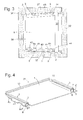
- FIG. 12 shows a more detailed perspective view of a refrigerated goods carrier 38 with reference to FIG Fig. 1
- the strips each comprise an extruded profile 4 made of aluminum and a plastic body 5 accommodated in a cavity of the extruded profile 4.
- the extruded profiles 4 have a cross-section similar to that described above the letter "a”, with a hollow lower portion 6, in the cavity of the plastic body 5 is inserted, and a hook-shaped over the lower portion 6 extending and with this one of the side edges 2 of the glass plate 1 receiving groove defining upper portion 7. An one remote from the glass plate 2 outer edge of the lower portion.
- Each strip 3 is formed with recesses 8a, 8b which are open at the bottom and which are provided to accommodate in each case one carrier cam 9 fastened to a side wall of a storage chamber receiving the refrigerated goods carrier.
- carrier cam 9 fastened to a side wall of a storage chamber receiving the refrigerated goods carrier.
- the plastic body 5 extend in the interior of the strips 3 to the rear end, where they each receive an end of a wire bracket 10.
- a central portion of this wire bracket 10 extends along the rear edge of the glass plate 1 above this, thus forming a railing that prevents refrigerated goods placed on the glass plate 1 is pushed up to the rear wall of the storage chamber and freezes at this.
- the distance in which the wire hanger 10 extends above the glass plate 1 is large enough for a user to grasp the wire hanger 10 with his fingers and thus use it as a handle for handling the chilled goods carrier 38 outside the refrigeration device.
- Fig. 5 shows in a perspective view of a support cam 9, of which four are each provided to be mounted on opposite side walls of a storage chamber of the refrigerator in pairs opposite to each other and the in Fig. 4 to support refrigerated goods 38 shown.
- the carrier cam 9 each comprises a flat plate 13, which is provided to abut the side wall 37 of the inner container 34, a in Fig. 5 non-visible projection which engages in a complementary shaped recess 40 of the side wall 37, and a pin 14 which is provided to engage in one of the recesses 8 of the refrigerated goods carrier 38.
- the pin 14 is octagonal in cross-section, with oblique facets 15, 18 at the top and bottom.
- the carrier cam 9 is mirror-symmetrical with respect to a vertical plane, so that a same type of carrier cam 9 can be mounted on the right and left side walls 37.
- Fig. 6 shows a side view of the refrigerated goods carrier 38, on which the relative movement of one of the strips 3 and the pin 14 is illustrated during assembly of the refrigerated goods carrier 38 in the refrigerator.
- the rear recess 8a is open to the rear, the front recess 8b is significantly wider than the pin 14, which it is to receive. This makes it easy, when placing the refrigerated goods carrier 38, the pin 14 to bring to engage in the recesses 8a, 8b.
- one of the oblique facets 15 at the top of the carrier cam 9 comes into contact with an obliquely upward and forward (to the right in the perspective of Fig. 6 ) extending inclined surface 16 of the front recess 8b.
- the contact between the facet 15 and the inclined surface 16 drives the refrigerated goods carrier 38 to the rear (or to the left in the Fig. 6 ), whereby both pins 14 engage in undercuts 17 at the front end sides of the recesses 8a, 8b.
- a parallel to the facet facet 18 18 at the bottom of each pin 14 in contact with an oblique lower edge 19 of the undercut 17.
- the inclined surface 16 and the oblique lower edge 19 of the recess 8b lead the front pin 14 substantially free of play.
- the refrigerated goods carrier 38 In the end position of the refrigerated goods carrier 38, in each of which a horizontal underside of the recesses 8a, 8b rests on horizontal upper sides of the pins 14, the refrigerated goods carrier 38 is stable and fixed free of play substantially in the depth direction. The pins 14 can therefore not disengage from the undercuts 17 without a simultaneous increase in the refrigerated goods carrier 38.
- a removal of the refrigerated goods carrier 38 by a user is not difficult, however, since the removal movement predetermined by the shape of the recesses 8 counteracts the tendency of a user to raise and to prefer a refrigerated goods carrier to be removed at the same time.
- Fig. 7 shows in a perspective view the already mentioned plastic body 5, which fills a cavity in the lower portion 6 of the extruded profile 4.
- the two recesses 8a, 8b can be seen.
- a further recess 21 is formed on the upper edge of the viewer facing edge above the inclined surface 16. In this recess 21 engages in the longitudinal direction of the plastic body 5 extending elastic tongue 22 a.
- a latching projection 23 at the free end of the tongue 22 is provided to, as in the cross section of Fig. 8 shown in a bore 30 of the extruded profile 4 to lock the plastic body 5 and so to fix the plastic body 5 in the extruded profile 4.
- the bore 30 is from below through the opening of Recess 8b driven through into the upper portion 7 of the profile 4 in and therefore no longer visible from the outside, as soon as the plastic body 5 is inserted into the extruded profile 4.
Landscapes
- Engineering & Computer Science (AREA)
- Chemical & Material Sciences (AREA)
- Combustion & Propulsion (AREA)
- Physics & Mathematics (AREA)
- Mechanical Engineering (AREA)
- Thermal Sciences (AREA)
- General Engineering & Computer Science (AREA)
- Devices That Are Associated With Refrigeration Equipment (AREA)
Applications Claiming Priority (1)
| Application Number | Priority Date | Filing Date | Title |
|---|---|---|---|
| DE102009028806A DE102009028806A1 (de) | 2009-08-21 | 2009-08-21 | Kältegerät mit Kühlgutträger |
Publications (2)
| Publication Number | Publication Date |
|---|---|
| EP2295904A2 true EP2295904A2 (fr) | 2011-03-16 |
| EP2295904A3 EP2295904A3 (fr) | 2017-05-10 |
Family
ID=43234225
Family Applications (1)
| Application Number | Title | Priority Date | Filing Date |
|---|---|---|---|
| EP10172875.6A Withdrawn EP2295904A3 (fr) | 2009-08-21 | 2010-08-16 | Appareil de refroidissement doté d'un support de produit réfrigéré |
Country Status (2)
| Country | Link |
|---|---|
| EP (1) | EP2295904A3 (fr) |
| DE (1) | DE102009028806A1 (fr) |
Family Cites Families (5)
| Publication number | Priority date | Publication date | Assignee | Title |
|---|---|---|---|---|
| US4914341A (en) * | 1989-03-23 | 1990-04-03 | White Consolidated Industries, Inc. | Refrigerator cabinet construction |
| DE4103334A1 (de) * | 1991-02-05 | 1992-08-06 | Bauknecht Hausgeraete | Kuehlgeraet |
| DE29923509U1 (de) * | 1999-05-29 | 2000-11-23 | Blanco GmbH & Co. KG, 75038 Oberderdingen | Auszugführung für einen aus einem Möbelkorpus ausziehbaren Einschub |
| US8182056B2 (en) * | 2007-09-05 | 2012-05-22 | Electrolux Home Products, Inc. | Offset weight supporting slide |
| DE102008040331A1 (de) * | 2008-07-10 | 2010-01-14 | BSH Bosch und Siemens Hausgeräte GmbH | Haushaltskühlgerät mit Abstützungen für einen Aufnahmeraum über seine Höhe unterteilende Fächer |
-
2009
- 2009-08-21 DE DE102009028806A patent/DE102009028806A1/de not_active Withdrawn
-
2010
- 2010-08-16 EP EP10172875.6A patent/EP2295904A3/fr not_active Withdrawn
Non-Patent Citations (1)
| Title |
|---|
| None |
Also Published As
| Publication number | Publication date |
|---|---|
| DE102009028806A1 (de) | 2011-02-24 |
| EP2295904A3 (fr) | 2017-05-10 |
Similar Documents
| Publication | Publication Date | Title |
|---|---|---|
| EP1896787B1 (fr) | Dispositif de support et appareil frigorifique equipe de celui-ci | |
| EP1846711B1 (fr) | Appareil a refroidir dote d'un porte-produits a refroidir coulissant | |
| EP0675332B1 (fr) | Réfrigérateur à rayons pour des marchandises à réfrigérer | |
| EP2118595A1 (fr) | Compartiment à beurre pour réfrigérateur | |
| WO2006120065A1 (fr) | Compartiment telescopique destine a un appareil frigorifique | |
| EP1848942B1 (fr) | Appareil frigorifique a support de denrees refrigerees telescopique | |
| EP2606298B1 (fr) | Un appareil frigorifique avec une étagère | |
| DE102005045329A1 (de) | Kältegerät mit Abstellplatte | |
| EP2531792B1 (fr) | Support à bouteille pour appareil frigorifique | |
| EP1481209B1 (fr) | Piece de bordure d'une plaque de verre | |
| EP2454541B1 (fr) | Support de produits à réfrigérer pour un appareil réfrigérant | |
| EP2295904A2 (fr) | Appareil de refroidissement doté d'un support de produit réfrigéré | |
| EP0582780B1 (fr) | Meuble comprenant des éléments porteurs pour étagères à introduire dans l'espace intérieur du meuble | |
| EP2980513B1 (fr) | Support de produit refrigere pour un appareil frigorifique | |
| EP2295903B1 (fr) | support de produit réfrigéré pour un appareil de refroidissement | |
| EP2295906A2 (fr) | Support de produit réfrigéré pour un appareil de refroidissement | |
| DE9210717U1 (de) | Tragteile zur Abstützung von Zwischenböden im Innenraum eines Möbels | |
| EP2317260A2 (fr) | Appareil frigorifique doté d'un support de produit réfrigéré amovible | |
| EP2156122B1 (fr) | Fond de rayonnage pour un appareil frigorifique | |
| EP1377782B1 (fr) | Bac a gla ons | |
| DE102007021570A1 (de) | Haushaltsgerät | |
| WO2006024654A1 (fr) | Porte pour un appareil de refrigeration | |
| DE102009002446A1 (de) | Kältegerät und Innenbehälter dafür | |
| DE102013224866A1 (de) | Kältegerät und Türabsteller dafür | |
| WO2012010442A2 (fr) | Appareil réfrigérant équipé d'un dispositif de sécurité pour le transport |
Legal Events
| Date | Code | Title | Description |
|---|---|---|---|
| PUAI | Public reference made under article 153(3) epc to a published international application that has entered the european phase |
Free format text: ORIGINAL CODE: 0009012 |
|
| AK | Designated contracting states |
Kind code of ref document: A2 Designated state(s): AL AT BE BG CH CY CZ DE DK EE ES FI FR GB GR HR HU IE IS IT LI LT LU LV MC MK MT NL NO PL PT RO SE SI SK SM TR |
|
| AX | Request for extension of the european patent |
Extension state: BA ME RS |
|
| RAP1 | Party data changed (applicant data changed or rights of an application transferred) |
Owner name: BSH HAUSGERAETE GMBH |
|
| PUAL | Search report despatched |
Free format text: ORIGINAL CODE: 0009013 |
|
| AK | Designated contracting states |
Kind code of ref document: A3 Designated state(s): AL AT BE BG CH CY CZ DE DK EE ES FI FR GB GR HR HU IE IS IT LI LT LU LV MC MK MT NL NO PL PT RO SE SI SK SM TR |
|
| AX | Request for extension of the european patent |
Extension state: BA ME RS |
|
| RIC1 | Information provided on ipc code assigned before grant |
Ipc: F25D 25/02 20060101AFI20170404BHEP |
|
| STAA | Information on the status of an ep patent application or granted ep patent |
Free format text: STATUS: REQUEST FOR EXAMINATION WAS MADE |
|
| 17P | Request for examination filed |
Effective date: 20171110 |
|
| RBV | Designated contracting states (corrected) |
Designated state(s): AL AT BE BG CH CY CZ DE DK EE ES FI FR GB GR HR HU IE IS IT LI LT LU LV MC MK MT NL NO PL PT RO SE SI SK SM TR |
|
| STAA | Information on the status of an ep patent application or granted ep patent |
Free format text: STATUS: EXAMINATION IS IN PROGRESS |
|
| 17Q | First examination report despatched |
Effective date: 20200612 |
|
| GRAP | Despatch of communication of intention to grant a patent |
Free format text: ORIGINAL CODE: EPIDOSNIGR1 |
|
| STAA | Information on the status of an ep patent application or granted ep patent |
Free format text: STATUS: GRANT OF PATENT IS INTENDED |
|
| INTG | Intention to grant announced |
Effective date: 20201019 |
|
| STAA | Information on the status of an ep patent application or granted ep patent |
Free format text: STATUS: THE APPLICATION IS DEEMED TO BE WITHDRAWN |
|
| 18D | Application deemed to be withdrawn |
Effective date: 20210302 |