EP2295845A1 - Lantern apparatus - Google Patents
Lantern apparatus Download PDFInfo
- Publication number
- EP2295845A1 EP2295845A1 EP09169798A EP09169798A EP2295845A1 EP 2295845 A1 EP2295845 A1 EP 2295845A1 EP 09169798 A EP09169798 A EP 09169798A EP 09169798 A EP09169798 A EP 09169798A EP 2295845 A1 EP2295845 A1 EP 2295845A1
- Authority
- EP
- European Patent Office
- Prior art keywords
- reflector
- flashlights
- main housing
- lantern
- lamp
- Prior art date
- Legal status (The legal status is an assumption and is not a legal conclusion. Google has not performed a legal analysis and makes no representation as to the accuracy of the status listed.)
- Withdrawn
Links
Images


Classifications
-
- F—MECHANICAL ENGINEERING; LIGHTING; HEATING; WEAPONS; BLASTING
- F21—LIGHTING
- F21L—LIGHTING DEVICES OR SYSTEMS THEREOF, BEING PORTABLE OR SPECIALLY ADAPTED FOR TRANSPORTATION
- F21L2/00—Systems of electric lighting devices
-
- F—MECHANICAL ENGINEERING; LIGHTING; HEATING; WEAPONS; BLASTING
- F21—LIGHTING
- F21L—LIGHTING DEVICES OR SYSTEMS THEREOF, BEING PORTABLE OR SPECIALLY ADAPTED FOR TRANSPORTATION
- F21L4/00—Electric lighting devices with self-contained electric batteries or cells
- F21L4/02—Electric lighting devices with self-contained electric batteries or cells characterised by the provision of two or more light sources
Definitions
- the present invention relates to a lantern apparatus for indoor or outdoor use, but which is especially convenient for outdoor use.
- United States Patent No. 4,004,132 discloses a toy camping set which includes a flashlight and lantern combination.
- the lantern includes a base structure having a receptacle for removably receiving and holding the flashlight with the beam of light from the flashlight directed generally downwardly when the lantern is held in its normal upright position.
- Connecting the receptacle with the base structure is a hollow tapered portion that is either translucent or transparent, and which surrounds a conical reflector.
- the flashlight includes a translucent or transparent lens member extending forwardly of its light bulb, and the forward (lower) end of the lens member fits on a shoulder of the reflector such that it completely surrounds the conical part of the reflector. In use, light emitted by the bulb of the flashlight is reflected by the conical reflector and travels through the lens member of the flashlight and through the hollow tapered portion, thereby escaping from the lantern.
- the present invention seeks to provide an improved lantern apparatus.
- the present invention provides a lantern apparatus, comprising: a main housing including a lamp and a reflector; and a plurality of flashlights that are removably engageable with the main housing; the apparatus arranged such that when the flashlights are engaged with the main housing they are spaced apart from the reflector and oriented so that light emitted from the flashlights is reflected by the reflector, the apparatus also being arranged such that both reflected light from the flashlights (reflected by the reflector), and light emitted by the lamp, is emitted from the main housing.
- the lantern apparatus of the present invention has several advantages over the flashlight and lantern combination of US 4,004,132 .
- the main advantages arise from the fact that the flashlights are spaced apart from the reflector when they are engaged with the main housing. This means, firstly, that it is not necessary to provide the flashlights with a special forwardly extending lens member to enable light reflected from the reflector to escape, and instead the flashlights can have a more conventional (and compact) design.
- spacing the flashlights from the reflector enables more than one flashlight to be provided, thereby enhancing the illumination from the lantern, and also enabling more than one person at a time to use a flashlight (when removed from the apparatus). The latter feature can be especially useful when camping, etc.
- spacing the flashlights from the reflector can improve both the intensity and spread of reflected illumination from the flashlights, because it enables greater freedom in the design of the reflector and its positioning relative to the flashlights, and also because the illumination can be provided by more than one flashlight.
- spacing the flashlights from the reflector enables a lamp also to be provided in the main housing, for example at least partially in and/or on the reflector. This has the further advantages of enabling yet brighter illumination and enabling one or more of the flashlights to be removed or turned off (e.g. to conserve power) as and when desired, while still enabling the lantern apparatus to provide illumination. Additional advantages may be apparent from the following description and claims.
- the main housing has at least one opening into which each flashlight may be at least partially inserted in order to engage with the main housing.
- the opening(s) may be permanently open, or may have a cap or other closure that can be moved to gain access thereto.
- the flashlights preferably engage with the main housing in the opening(s).
- the main housing includes a cavity in which the reflector is located, and through which light emitted by the flashlights travels before striking the reflector.
- the cavity preferably has a transparent or translucent wall through which the light emitted from the main housing travels (i.e. light emitted by the flashlights and reflected from the reflector, and light emitted by the lamp).
- the opening(s) of the main housing may be located at an end of the cavity (e.g. an upper end, according to a normal orientation of the main housing, in use).
- the reflector is located at or near an opposite end of the cavity to the end at which the opening(s) is/are located (e.g. a lower end).
- the flashlights preferably extend at least partially into the cavity when they are engaged with the main housing, e.g. in a generally downwardly-pointing orientation (i.e. with their light beams directed generally downwards).
- the flashlights may, for example, engage with the housing by an interference fit (e.g. assisted by gravity) or by an interlocking engagement.
- each flashlight is arranged (e.g. sized and shaped) to have an interference fit with a respective opening.
- the reflector preferably has an at least partially reflective surface that is concave and/or convex and/or flared and/or at least partially conical.
- the reflector may have a generally domed (or partially domed) shape, or it may be generally conical (or frusto-conical), or flared conical/frusto-conical.
- other shapes of reflector are possible.
- the lamp may be situated at least partially in and/or on the reflector.
- the lamp preferably includes a transparent or translucent cover through which at least a portion of its light is emitted.
- the lamp cover may, for example, be located on, or adjacent to, the reflective surface of the reflector.
- the lamp cover may comprise at least a portion of the reflector, e.g. at least a portion of the reflective surface of the reflector. At least that portion of the reflective surface may be partially reflective and partially transmissive to light, thereby reflecting at least some of the light from the flashlights while allowing at least some of the light from the lamp to escape.
- the flashlights preferably are battery powered, and preferably hold their own batteries (which may, or may not, be rechargeable).
- the lamp may be powered by mains electricity, but preferably it is battery powered (either instead of, or in addition to, being mains powered). Consequently, the lantern apparatus preferably further comprises a part of the housing arranged to accommodate a portable power supply for the lamp.
- each flashlight may include a handle portion, the handle portions extending at least partially out of the housing when the flashlights are engaged therewith.
- the handle portion of each flashlight preferably includes an actuation switch for the flashlight (e.g. on an end of the handle portion), which is accessible from the exterior of the housing when the flashlight is engaged therewith.
- the lantern apparatus may include electrical contacts on at least one of the flashlights (but preferably on each of them) and on the main housing, such that the flashlight(s) can be in electrical contact with components in the main housing when engaged therewith.
- the main housing may include a battery charger, arranged to charge one or more flashlight batteries when the flashlight(s) is/are engaged with the main housing.
- the charger may additionally or alternatively be arranged to charge one or more batteries for powering the lamp.
- the lantern apparatus (especially the main housing) preferably includes a base by which the apparatus may be supported on a surface.
- the transparent or translucent wall of the cavity is mounted on the base.
- the base may, for example contain a portable power supply (e.g. one or more batteries) for the lamp and/or charging circuitry, e.g. for the lamp batteries and/or for the flashlight batteries.
- the lantern apparatus may include at least one light (e.g. one or more light emitting diodes, or other light emitter(s)) arranged to illuminate automatically when an AC mains electrical power supply to the lantern is interrupted (e.g. in the event of a power failure).
- the light (which may be described as an emergency light) may be powered by one or more rechargeable batteries, and in use may be connected to the mains electricity supply, e.g. via a battery charger.
- the emergency light may be additional to the lamp and/or (at least in some embodiments of the invention) it may be the lamp itself.
- the lantern apparatus (especially the main housing) preferably includes a handle by which the apparatus may be carried.
- the handle and/or another part of the main housing may include a hook or other attachment device for attaching the lantern apparatus to another structure.
- the main housing preferably is formed entirely or in part from polymeric materials.
- the light emitting components of the flashlights and the lamp may be, for example, incandescent bulbs and/or fluorescent bulbs and/or light emitting diodes (LEDs), or substantially any suitable electrically powered components.
- LEDs light emitting diodes
- Light emitting diodes especially bright white light emitting LEDs
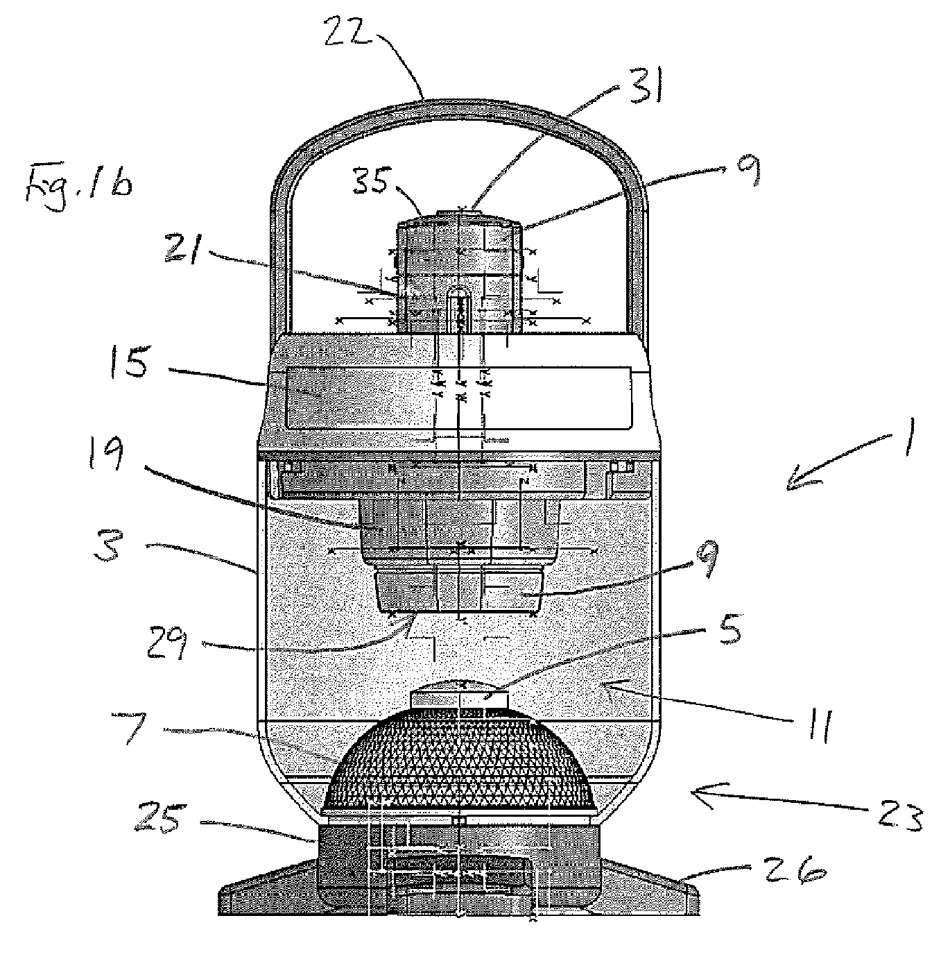
- FIG. 1 shows a lantern apparatus 1 according to the invention, comprising a main housing 3 which includes a lamp 5 and a reflector 7, and two flashlights 9.
- the main housing 3 defines a cavity 11 having a transparent or translucent side wall 13 which, in the illustrated embodiment, is generally cylindrical in shape.
- An upper end 15 of the main housing 3 includes a pair of openings 17, each of which is arranged to receive a respective flashlight 9.
- the openings 17 extend, by means of extensions 19, into the cavity 11, and the flashlights 9 and the openings are arranged so that the flashlights are engaged with the main housing in the openings by means of a gravity-assisted interference fit.
- each flashlight 9 is removable from its respective opening 17 by grasping a handle portion 21 of the flashlight and pulling it upwardly with respect to the main housing 3. After each flashlight has been used (independently of the remainder of the lantern assembly) it may be returned to the main housing by inserting it into a respective opening 17.
- the upper end 15 of the main housing 3 also includes a pivoting handle 22 by which the lantern apparatus may be lifted and carried.
- a hook or other attachment member may also be provided, for example on the handle 22, for attaching the lantern apparatus to other structures.
- the reflector 7 comprises a reflective (e.g. mirrored) dome, the top part of which supports the lamp 5.
- the lamp 5 includes a transparent or translucent cover which covers one or more light emitting components, preferably light emitting diodes (but other light emitters, such as incandescent or fluorescent bulbs can be used). Components of the lamp 5 and its electrical circuitry are housed within the reflector 7.
- the reflector 7 as shown in Figure 1 may be at least partially transmissive to light from its interior, so that at least part of the lamp 5 may be located inside the reflector and emit at least some of its light through the reflector.
- the reflector 7 may be partially reflective, e.g. a faceted transparent or translucent structure arranged to refract and reflect light.
- a base 25 of the main housing 3 which supports the remainder of the main housing (and the flashlights when they are engaged with the main housing).
- the base 25 includes three supporting legs 26, and accommodates one or more batteries for the lamp 5.
- the base 25 and/or the reflector 7 may also house electrical charging circuitry for charging the batteries.
- a mains electrical power cable may extend from the base 25, for powering the lamp 5 and/or the charger.
- Figure 2 illustrates a second embodiment of the invention which is substantially the same as the embodiment illustrated in Figure 1 (views (a) to (c)), but which has a differently shaped reflector 7a.
- the reflector 7a has the shape of a truncated flared cone, with the lamp 5 sitting on top of the truncated region.
- Figure 2 also shows an actuating switch 27 for the lamp 5 on the base 25.
- the Figure 1 embodiment also has a switch for the lamp 5 on the base 25, but it is not illustrated.
- both versions of the lantern apparatus 1 are arranged such that when the flashlights 9 are engaged with the main housing they are spaced apart from the reflector 7, 7a and oriented so that light emitted (downwardly as drawn) from the flashlights is reflected by the reflector. Both reflected light from the flashlights 9, and light emitted by the lamp 5, is emitted from the main housing 3 through the transparent or translucent wall 13.
- FIG 2c shows the lantern apparatus with the flashlights 9 removed
- Figure 2d shows one of the removed flashlights 9.
- Each flashlight 9 is generally conventional in shape and construction, being generally elongate and having a forward light emitting part 29, the handle portion 21 behind this, which handle portion houses batteries for powering the flashlight, and a push-button actuating switch 31 on a rear end 35 of the flashlight housing. This arrangement enables the flashlights to be easily withdrawn from, and inserted into, the main housing 3 of the lantern apparatus, and to be switched on and off when they are engaged with the main housing.
Abstract
A lantern apparatus comprises a main housing including a lamp and a reflector, and a plurality of flashlights that are removably engageable with the main housing. The apparatus is arranged such that when the flashlights are engaged with the main housing they are spaced apart from the reflector and oriented so that light emitted from the flashlights is reflected by the reflector. Both the reflected light from the flashlights, and light emitted by the lamp, is emitted from the main housing.

Description
- The present invention relates to a lantern apparatus for indoor or outdoor use, but which is especially convenient for outdoor use.
- United States Patent No.
4,004,132 discloses a toy camping set which includes a flashlight and lantern combination. The lantern includes a base structure having a receptacle for removably receiving and holding the flashlight with the beam of light from the flashlight directed generally downwardly when the lantern is held in its normal upright position. Connecting the receptacle with the base structure is a hollow tapered portion that is either translucent or transparent, and which surrounds a conical reflector. The flashlight includes a translucent or transparent lens member extending forwardly of its light bulb, and the forward (lower) end of the lens member fits on a shoulder of the reflector such that it completely surrounds the conical part of the reflector. In use, light emitted by the bulb of the flashlight is reflected by the conical reflector and travels through the lens member of the flashlight and through the hollow tapered portion, thereby escaping from the lantern. - The present invention seeks to provide an improved lantern apparatus.
- The present invention provides a lantern apparatus, comprising: a main housing including a lamp and a reflector; and a plurality of flashlights that are removably engageable with the main housing; the apparatus arranged such that when the flashlights are engaged with the main housing they are spaced apart from the reflector and oriented so that light emitted from the flashlights is reflected by the reflector, the apparatus also being arranged such that both reflected light from the flashlights (reflected by the reflector), and light emitted by the lamp, is emitted from the main housing.
- The lantern apparatus of the present invention has several advantages over the flashlight and lantern combination of
US 4,004,132 . The main advantages arise from the fact that the flashlights are spaced apart from the reflector when they are engaged with the main housing. This means, firstly, that it is not necessary to provide the flashlights with a special forwardly extending lens member to enable light reflected from the reflector to escape, and instead the flashlights can have a more conventional (and compact) design. Secondly, in contrast with the arrangement inUS 4,004,132 , spacing the flashlights from the reflector enables more than one flashlight to be provided, thereby enhancing the illumination from the lantern, and also enabling more than one person at a time to use a flashlight (when removed from the apparatus). The latter feature can be especially useful when camping, etc. Thirdly, spacing the flashlights from the reflector can improve both the intensity and spread of reflected illumination from the flashlights, because it enables greater freedom in the design of the reflector and its positioning relative to the flashlights, and also because the illumination can be provided by more than one flashlight. Fourthly, spacing the flashlights from the reflector enables a lamp also to be provided in the main housing, for example at least partially in and/or on the reflector. This has the further advantages of enabling yet brighter illumination and enabling one or more of the flashlights to be removed or turned off (e.g. to conserve power) as and when desired, while still enabling the lantern apparatus to provide illumination. Additional advantages may be apparent from the following description and claims. - Preferably, the main housing has at least one opening into which each flashlight may be at least partially inserted in order to engage with the main housing. The opening(s) may be permanently open, or may have a cap or other closure that can be moved to gain access thereto. The flashlights preferably engage with the main housing in the opening(s).
- In preferred embodiments of the invention, the main housing includes a cavity in which the reflector is located, and through which light emitted by the flashlights travels before striking the reflector. The cavity preferably has a transparent or translucent wall through which the light emitted from the main housing travels (i.e. light emitted by the flashlights and reflected from the reflector, and light emitted by the lamp). Advantageously, the opening(s) of the main housing may be located at an end of the cavity (e.g. an upper end, according to a normal orientation of the main housing, in use). Preferably, the reflector is located at or near an opposite end of the cavity to the end at which the opening(s) is/are located (e.g. a lower end). The flashlights preferably extend at least partially into the cavity when they are engaged with the main housing, e.g. in a generally downwardly-pointing orientation (i.e. with their light beams directed generally downwards). The flashlights may, for example, engage with the housing by an interference fit (e.g. assisted by gravity) or by an interlocking engagement. Preferably, each flashlight is arranged (e.g. sized and shaped) to have an interference fit with a respective opening.
- The reflector preferably has an at least partially reflective surface that is concave and/or convex and/or flared and/or at least partially conical. For example, the reflector may have a generally domed (or partially domed) shape, or it may be generally conical (or frusto-conical), or flared conical/frusto-conical. However, other shapes of reflector are possible. The lamp may be situated at least partially in and/or on the reflector.
- The lamp preferably includes a transparent or translucent cover through which at least a portion of its light is emitted. The lamp cover may, for example, be located on, or adjacent to, the reflective surface of the reflector.
- In some embodiments of the invention, the lamp cover may comprise at least a portion of the reflector, e.g. at least a portion of the reflective surface of the reflector. At least that portion of the reflective surface may be partially reflective and partially transmissive to light, thereby reflecting at least some of the light from the flashlights while allowing at least some of the light from the lamp to escape.
- The flashlights preferably are battery powered, and preferably hold their own batteries (which may, or may not, be rechargeable). The lamp may be powered by mains electricity, but preferably it is battery powered (either instead of, or in addition to, being mains powered). Consequently, the lantern apparatus preferably further comprises a part of the housing arranged to accommodate a portable power supply for the lamp.
- Advantageously, each flashlight may include a handle portion, the handle portions extending at least partially out of the housing when the flashlights are engaged therewith. The handle portion of each flashlight preferably includes an actuation switch for the flashlight (e.g. on an end of the handle portion), which is accessible from the exterior of the housing when the flashlight is engaged therewith.
- In at least some embodiments of the invention, the lantern apparatus may include electrical contacts on at least one of the flashlights (but preferably on each of them) and on the main housing, such that the flashlight(s) can be in electrical contact with components in the main housing when engaged therewith. For example, the main housing may include a battery charger, arranged to charge one or more flashlight batteries when the flashlight(s) is/are engaged with the main housing. The charger may additionally or alternatively be arranged to charge one or more batteries for powering the lamp.
- The lantern apparatus (especially the main housing) preferably includes a base by which the apparatus may be supported on a surface. Preferably the transparent or translucent wall of the cavity is mounted on the base. The base may, for example contain a portable power supply (e.g. one or more batteries) for the lamp and/or charging circuitry, e.g. for the lamp batteries and/or for the flashlight batteries.
- In at least some preferred embodiments of the invention, the lantern apparatus may include at least one light (e.g. one or more light emitting diodes, or other light emitter(s)) arranged to illuminate automatically when an AC mains electrical power supply to the lantern is interrupted (e.g. in the event of a power failure). For example, the light (which may be described as an emergency light) may be powered by one or more rechargeable batteries, and in use may be connected to the mains electricity supply, e.g. via a battery charger. The emergency light may be additional to the lamp and/or (at least in some embodiments of the invention) it may be the lamp itself.
- The lantern apparatus (especially the main housing) preferably includes a handle by which the apparatus may be carried. The handle and/or another part of the main housing may include a hook or other attachment device for attaching the lantern apparatus to another structure.
- The main housing preferably is formed entirely or in part from polymeric materials.
- The light emitting components of the flashlights and the lamp may be, for example, incandescent bulbs and/or fluorescent bulbs and/or light emitting diodes (LEDs), or substantially any suitable electrically powered components. Light emitting diodes (especially bright white light emitting LEDs) currently are particularly preferred, because they are highly efficient and generate very little heat.
- Preferred embodiments of the invention will now be described, by way of example, with reference to the accompanying drawings, of which:
-
Figure 1 ((a) to (c)) shows three views of a first embodiment of a lantern assembly according to the invention; and -
Figure 2 ((a) to (d)) shows four views of a second embodiment of a lantern assembly according to the invention, and parts thereof. -
Figure 1 shows a lantern apparatus 1 according to the invention, comprising amain housing 3 which includes alamp 5 and areflector 7, and twoflashlights 9. Themain housing 3 defines acavity 11 having a transparent or translucent side wall 13 which, in the illustrated embodiment, is generally cylindrical in shape. Anupper end 15 of themain housing 3 includes a pair ofopenings 17, each of which is arranged to receive arespective flashlight 9. Theopenings 17 extend, by means ofextensions 19, into thecavity 11, and theflashlights 9 and the openings are arranged so that the flashlights are engaged with the main housing in the openings by means of a gravity-assisted interference fit. Thus, eachflashlight 9 is removable from itsrespective opening 17 by grasping ahandle portion 21 of the flashlight and pulling it upwardly with respect to themain housing 3. After each flashlight has been used (independently of the remainder of the lantern assembly) it may be returned to the main housing by inserting it into arespective opening 17. - The
upper end 15 of themain housing 3 also includes apivoting handle 22 by which the lantern apparatus may be lifted and carried. A hook or other attachment member may also be provided, for example on thehandle 22, for attaching the lantern apparatus to other structures. - Towards a
lower end 23 of themain housing 3, inside thecavity 11, are thelamp 5 andreflector 7. Thereflector 7 comprises a reflective (e.g. mirrored) dome, the top part of which supports thelamp 5. Thelamp 5 includes a transparent or translucent cover which covers one or more light emitting components, preferably light emitting diodes (but other light emitters, such as incandescent or fluorescent bulbs can be used). Components of thelamp 5 and its electrical circuitry are housed within thereflector 7. - In some embodiments of the invention, the
reflector 7 as shown inFigure 1 (and/orFigure 2 ) may be at least partially transmissive to light from its interior, so that at least part of thelamp 5 may be located inside the reflector and emit at least some of its light through the reflector. Thus, in some versions of the invention, thereflector 7 may be partially reflective, e.g. a faceted transparent or translucent structure arranged to refract and reflect light. However, it is generally preferred for the reflector not to be transmissive of light therethrough, but instead to reflect light from its exterior, and to have the light emitting part of thelamp 5 adjacent to its exterior. - Below the
reflector 7 and the transparent or translucent wall 13 is abase 25 of themain housing 3, which supports the remainder of the main housing (and the flashlights when they are engaged with the main housing). Thebase 25 includes three supportinglegs 26, and accommodates one or more batteries for thelamp 5. Thebase 25 and/or thereflector 7 may also house electrical charging circuitry for charging the batteries. In at least some versions, a mains electrical power cable may extend from thebase 25, for powering thelamp 5 and/or the charger. -
Figure 2 (views (a) to (d)) illustrates a second embodiment of the invention which is substantially the same as the embodiment illustrated inFigure 1 (views (a) to (c)), but which has a differently shapedreflector 7a. In theFigure 2 embodiment, thereflector 7a has the shape of a truncated flared cone, with thelamp 5 sitting on top of the truncated region.Figure 2 also shows anactuating switch 27 for thelamp 5 on thebase 25. (TheFigure 1 embodiment also has a switch for thelamp 5 on thebase 25, but it is not illustrated.) - As illustrated, both versions of the lantern apparatus 1 are arranged such that when the
flashlights 9 are engaged with the main housing they are spaced apart from thereflector flashlights 9, and light emitted by thelamp 5, is emitted from themain housing 3 through the transparent or translucent wall 13. -
Figure 2c shows the lantern apparatus with theflashlights 9 removed, andFigure 2d shows one of the removedflashlights 9. Eachflashlight 9 is generally conventional in shape and construction, being generally elongate and having a forwardlight emitting part 29, thehandle portion 21 behind this, which handle portion houses batteries for powering the flashlight, and a push-button actuating switch 31 on arear end 35 of the flashlight housing. This arrangement enables the flashlights to be easily withdrawn from, and inserted into, themain housing 3 of the lantern apparatus, and to be switched on and off when they are engaged with the main housing. - It will be understood that the above description and the drawings are of particular examples of the invention, but that other examples of the invention are included in the scope of the claims.
Claims (15)
- A lantern apparatus, comprising: a main housing including a lamp and a reflector; and a plurality of flashlights that are removably engageable with the main housing; the apparatus arranged such that when the flashlights are engaged with the main housing they are spaced apart from the reflector and oriented so that light emitted from the flashlights is reflected by the reflector, the apparatus also being arranged such that both reflected light from the flashlights, and light emitted by the lamp, is emitted from the main housing.
- A lantern apparatus according to claim 1, in which the main housing has at least one opening into which each flashlight may be at least partially inserted in order to engage with the main housing.
- A lantern apparatus according to any preceding claim, in which the main housing includes a cavity in which the reflector is located, and through which light emitted by the flashlights travels before striking the reflector.
- A lantern apparatus according to claim 3 when dependent upon claim 2, in which the, or each, opening is located at an end of the cavity.
- A lantern apparatus according to claim 4, in which the reflector is located at or near an opposite end of the cavity to the end at which the, or each, opening is located.
- A lantern apparatus according to any one of claims 3 to 5, in which the flashlights extend at least partially into the cavity when they are engaged with the main housing.
- A lantern apparatus according to any one of claims 3 to 6, in which the cavity has a transparent or translucent wall through which the light emitted from the main housing travels.
- A lantern apparatus according to any preceding claim, in which the flashlights engage with the housing by an interference fit or by an interlocking engagement.
- A lantern apparatus according to any preceding claim, in which the reflector has an at least partially reflective surface that is concave and/or convex and/or flared and/or at least partially conical.
- A lantern apparatus according to any preceding claim, in which the lamp is situated at least partially in and/or on the reflector.
- A lantern apparatus according to any preceding claim, in which the lamp includes a transparent or translucent cover through which at least a portion of its light is emitted.
- A lantern apparatus according to claim 11, in which the cover is located on or adjacent to the reflective surface of the reflector, or in which the cover comprises at least a portion of the reflector.
- A lantern apparatus according to any preceding claim, further comprising a part of the housing arranged to accommodate a portable power supply for the lamp.
- A lantern apparatus according to any preceding claim, in which each flashlight includes a handle portion, the handle portions extending at least partially out of the housing when the flashlights are engaged therewith.
- A lantern apparatus according to claim 14, in which the handle portion of each flashlight includes an actuation switch for the flashlight, which is accessible from the exterior of the housing when the flashlight is engaged therewith.
Priority Applications (3)
| Application Number | Priority Date | Filing Date | Title |
|---|---|---|---|
| EP09169798A EP2295845A1 (en) | 2009-09-09 | 2009-09-09 | Lantern apparatus |
| US12/876,406 US20110058361A1 (en) | 2009-09-09 | 2010-09-07 | Lantern apparatus |
| CN2010102784443A CN102022621A (en) | 2009-09-09 | 2010-09-08 | Lantern apparatus |
Applications Claiming Priority (1)
| Application Number | Priority Date | Filing Date | Title |
|---|---|---|---|
| EP09169798A EP2295845A1 (en) | 2009-09-09 | 2009-09-09 | Lantern apparatus |
Publications (1)
| Publication Number | Publication Date |
|---|---|
| EP2295845A1 true EP2295845A1 (en) | 2011-03-16 |
Family
ID=41571578
Family Applications (1)
| Application Number | Title | Priority Date | Filing Date |
|---|---|---|---|
| EP09169798A Withdrawn EP2295845A1 (en) | 2009-09-09 | 2009-09-09 | Lantern apparatus |
Country Status (3)
| Country | Link |
|---|---|
| US (1) | US20110058361A1 (en) |
| EP (1) | EP2295845A1 (en) |
| CN (1) | CN102022621A (en) |
Families Citing this family (6)
| Publication number | Priority date | Publication date | Assignee | Title |
|---|---|---|---|---|
| US8386034B2 (en) * | 2010-09-22 | 2013-02-26 | Physio-Control, Inc. | Defibrillator with utility light |
| US20160348879A1 (en) * | 2015-05-29 | 2016-12-01 | Black & Decker Inc. | Work Light |
| CN210424565U (en) * | 2016-12-06 | 2020-04-28 | 科尔曼公司 | Lamp device |
| US20180266657A1 (en) * | 2017-03-14 | 2018-09-20 | Led Lenser Corp. Ltd. | Apparatus and system for a compact illumination device |
| US10823344B2 (en) | 2017-12-28 | 2020-11-03 | Heathco Llc | Portable decorative lantern and related methods |
| US11125418B2 (en) | 2019-11-22 | 2021-09-21 | Shawshank Ledz Inc. | Modular device with interchangeable torch lantern functionalities |
Citations (3)
| Publication number | Priority date | Publication date | Assignee | Title |
|---|---|---|---|---|
| US4004132A (en) * | 1973-02-20 | 1977-01-18 | Marvin Glass & Associates | Convertible flashlight-lantern |
| US6260985B1 (en) * | 1999-07-23 | 2001-07-17 | Noel E. Zeller | Multipurpose portable electric lighting apparatus |
| US20050128740A1 (en) * | 2003-09-03 | 2005-06-16 | Currie Robert M. | Multipurpose led flashlights and components thereof |
Family Cites Families (3)
| Publication number | Priority date | Publication date | Assignee | Title |
|---|---|---|---|---|
| US7097322B2 (en) * | 2003-09-10 | 2006-08-29 | Lawrence Shuniak | Illumination device having detachable lighting units |
| US20090135611A1 (en) * | 2007-11-26 | 2009-05-28 | Quasar Optoelectronics, Inc. | Multi-functional lantern |
| US8087797B2 (en) * | 2008-07-18 | 2012-01-03 | Stanley Black & Decker, Inc. | Illumination device with detachable light sources |
-
2009
- 2009-09-09 EP EP09169798A patent/EP2295845A1/en not_active Withdrawn
-
2010
- 2010-09-07 US US12/876,406 patent/US20110058361A1/en not_active Abandoned
- 2010-09-08 CN CN2010102784443A patent/CN102022621A/en active Pending
Patent Citations (3)
| Publication number | Priority date | Publication date | Assignee | Title |
|---|---|---|---|---|
| US4004132A (en) * | 1973-02-20 | 1977-01-18 | Marvin Glass & Associates | Convertible flashlight-lantern |
| US6260985B1 (en) * | 1999-07-23 | 2001-07-17 | Noel E. Zeller | Multipurpose portable electric lighting apparatus |
| US20050128740A1 (en) * | 2003-09-03 | 2005-06-16 | Currie Robert M. | Multipurpose led flashlights and components thereof |
Also Published As
| Publication number | Publication date |
|---|---|
| CN102022621A (en) | 2011-04-20 |
| US20110058361A1 (en) | 2011-03-10 |
Similar Documents
| Publication | Publication Date | Title |
|---|---|---|
| US9303853B2 (en) | Collapsible light | |
| US7400112B2 (en) | Autoilluminating rechargeable lamp system | |
| JP5023220B2 (en) | Lantern with removable light | |
| US20110058361A1 (en) | Lantern apparatus | |
| US7325944B2 (en) | Rechargeable LED utility light | |
| CA2505668C (en) | Autoilluminating rechargeable lamp system | |
| US6575613B2 (en) | Portable special effects illumination device | |
| US8672506B2 (en) | Solar candle light insert module | |
| US7150540B2 (en) | Rechargeable LED utility light | |
| US20050264261A1 (en) | Autoilluminating rechargeable lamp system | |
| US8421252B1 (en) | Solar wind chime | |
| US7784964B2 (en) | Convertible light device | |
| CN212156723U (en) | Lamp assembly | |
| US20140265905A1 (en) | Switchable Light Bulb Assembly with Integral Power Source | |
| KR20120052655A (en) | Multipurpose lantern | |
| US20090207597A1 (en) | Rechargeable Light Assembly | |
| US6685337B2 (en) | Combination flashlight and candle lantern | |
| US7097322B2 (en) | Illumination device having detachable lighting units | |
| AU2011209798A1 (en) | Folding spotlight | |
| KR101097491B1 (en) | a portable lamp | |
| US20180156403A1 (en) | Thermoelectric lamp | |
| KR101413703B1 (en) | portable illumination | |
| US8672527B2 (en) | Luminous light apparatus | |
| CN210568042U (en) | Lamp fitting | |
| CN206943873U (en) | A kind of portable barn lantern of multi-functional Chargeable lighting |
Legal Events
| Date | Code | Title | Description |
|---|---|---|---|
| PUAI | Public reference made under article 153(3) epc to a published international application that has entered the european phase |
Free format text: ORIGINAL CODE: 0009012 |
|
| AK | Designated contracting states |
Kind code of ref document: A1 Designated state(s): AT BE BG CH CY CZ DE DK EE ES FI FR GB GR HR HU IE IS IT LI LT LU LV MC MK MT NL NO PL PT RO SE SI SK SM TR |
|
| AX | Request for extension of the european patent |
Extension state: AL BA RS |
|
| 17P | Request for examination filed |
Effective date: 20110908 |
|
| 17Q | First examination report despatched |
Effective date: 20110926 |
|
| STAA | Information on the status of an ep patent application or granted ep patent |
Free format text: STATUS: THE APPLICATION IS DEEMED TO BE WITHDRAWN |
|
| 18D | Application deemed to be withdrawn |
Effective date: 20120411 |