EP2295822A1 - Screw connection with threaded bolt and nut - Google Patents
Screw connection with threaded bolt and nut Download PDFInfo
- Publication number
- EP2295822A1 EP2295822A1 EP10174275A EP10174275A EP2295822A1 EP 2295822 A1 EP2295822 A1 EP 2295822A1 EP 10174275 A EP10174275 A EP 10174275A EP 10174275 A EP10174275 A EP 10174275A EP 2295822 A1 EP2295822 A1 EP 2295822A1
- Authority
- EP
- European Patent Office
- Prior art keywords
- thread
- nut
- threaded bolt
- exterior
- interior
- Prior art date
- Legal status (The legal status is an assumption and is not a legal conclusion. Google has not performed a legal analysis and makes no representation as to the accuracy of the status listed.)
- Granted
Links
Images
Classifications
-
- F—MECHANICAL ENGINEERING; LIGHTING; HEATING; WEAPONS; BLASTING
- F16—ENGINEERING ELEMENTS AND UNITS; GENERAL MEASURES FOR PRODUCING AND MAINTAINING EFFECTIVE FUNCTIONING OF MACHINES OR INSTALLATIONS; THERMAL INSULATION IN GENERAL
- F16B—DEVICES FOR FASTENING OR SECURING CONSTRUCTIONAL ELEMENTS OR MACHINE PARTS TOGETHER, e.g. NAILS, BOLTS, CIRCLIPS, CLAMPS, CLIPS OR WEDGES; JOINTS OR JOINTING
- F16B37/00—Nuts or like thread-engaging members
- F16B37/005—Nuts or like thread-engaging members into which threads are cut during screwing
Definitions
- the invention relates to a screw connection with a threaded bolt and a nut that may be screwed thereon, with the exterior thread of the threaded bolt and the interior thread of the nut having the same incline and the same thread angle and with a material being used for the nut that is softer, at least in the region of the interior thread, than a material used for the threaded bolt, at least in the region of the exterior thread.
- the invention further relates to a nut made of plastic for such a screw connection.
- a screw connection of the type mentioned above is known from DE 198 57 225 A1 .
- This screw connection is used to fasten a gas pedal module to the body of a motor vehicle and is intended for automatic bolting processes.
- the threaded bolt has a metric standard unified thread having a thread angle of 60 degrees and the interior thread of the nut, before being screwed onto the threaded bolt, has an outer diameter that is less than the outer diameter of the exterior thread of the threaded bolt.
- the interior and exterior threads must be very dimensionally stable so that the nut is not overloaded.
- German published patent application DE 2,903,845 A1 discloses various embodiments of a screw connection with a thread that is not quite completely cut. In the embodiments described, however, the thread angle of the interior thread of the nut and the thread angle of the exterior thread of the bolt are different, so that the deformation of the thread tips of the exterior thread of the bolt does not cause jamming between the bolt and the nut. The durability of the screw connection is reduced by these different thread angles.
- FR 1,343,518 A discloses a self-securing nut, the interior thread of which has a slightly smaller inner diameter and a slightly smaller outer diameter as compared to the standard unified thread. This is intended to generate a sufficient torque against loosening when bolted onto a threaded bolt with a corresponding standard unified thread.
- the known design is not suitable for securing nuts made of plastic from loosening due to their high degree of elasticity and the cold flow behavior of plastics.
- JP 09-112,522 A discloses a threaded bolt made of plastic whose exterior thread is a trapezoidal thread having flanks of different widths and a radially outermost boundary surface that is inclined toward the central axis of the threaded bolt in order to facilitate the force fitting of the threaded bolt into a receiving bore.
- the object of the invention is to create a screw connection of the type mentioned at the outset in which the nut screwed onto the threaded bolt is secured against loosening by a torque, with only a relatively small amount of torque being required to screw the nut onto the threaded bolt.
- the nut should be prevented from breaking while being screwed on.
- the screw connection according to the invention comprises a threaded bolt and a nut to be screwed thereon, with the threaded bolt being provided with an exterior thread provided with a thread rib in the style of a trapeze thread having flanks converging radially outwards that are straight in profile and a radially exterior boundary surface located therebetween, with the nut having a bore provided over at least part of its length with an interior thread formed by a thread groove, with the thread groove having flanks converging radially outwards that are straight in profile, which transition radially outwards in a continuous fashion into a round section forming the thread base of the thread groove, with a material being used for the nut that is softer, at least in the region of the interior thread, than a material used for the threaded bolt, at least in the region of its exterior thread, with outer diameter of the exterior thread of the threaded bolt being greater than the diameter of an imaginary coaxial cylinder whose outer surface separates the flank sections of the interior thread of the nut before being screw
- the outer diameter of the interior thread of the nut is the diameter of an imaginary cylinder that is coaxial to the interior thread and whose surface lines touch the thread base of the interior thread and the outer diameter of the exterior thread of the threaded bolt is equal to double the greatest radius of the radially outermost boundary surface of the thread rib of the exterior thread.
- the screw connection according to the invention allows an easy and reliable bolting and attains a high degree of self-locking momentum after bolting.
- the radial load on the nut remains relatively small and the shape of the interior thread reduces the risk of breakage to the nut.
- the radially outermost boundary surface of the thread rib of the exterior thread of the threaded bolt may be part of a cylindrical surface, with the outer diameter of the exterior thread of the threaded bolt being smaller than the outer diameter of the interior thread of the nut.
- the radially outermost boundary surface of the thread rib of the exterior thread of the threaded bolt is inclined relative to the central axis of the threaded bolt such that the outer diameter of the thread flank facing the threaded end is smaller than the outer diameter of the thread flank facing away from the threaded end, with the outer diameter of the interior thread of the nut being approximately equal to or less than the outer diameter of the exterior thread of the threaded bolt.
- the effective load-bearing flanks of the nut and threaded bolt have a greater width, such that the screw connection has a greater resilience. It has been shown to be advantageous for the radially outermost boundary surface of the thread rib to be inclined such that a radial line touching the radially outermost boundary surface would intersect with the central axis of the threaded bolt at an angle of approximately 30 degrees.
- the diameter of an imaginary cylinder that intersects with the inclined radially outermost boundary surface of the thread rib in the center may be smaller than the outer diameter of the interior thread of the nut. This results in a hollow space between the radially outermost boundary surface and the thread base of the interior thread of the bolt that is able to accommodate material displaced by the thread rib.
- the nut is prevented from being locked too tightly while being screwed on, and the nut is prevented from bearing too great a load.
- the screw connection comprises a nut made of plastic having a bore provided over at least a portion of its length with an interior thread formed by a thread groove, with the thread groove having a thread profile that has straight flank sections converging radially outward in the manner of a trapezoidal thread which transition radially outwards in a continuous fashion into a round section forming the thread base of the thread groove.
- a nut is break-proof and may be produced as one piece in a simple and cost-effective manner by means of master forming.
- the flank angle of the flank sections of the nut may be 25 to 35 degrees, particularly 30 degrees.
- the bore of the nut prefferably has a threaded end having an insertion section that has an inner diameter sized such that the nut, along with the insertion section, may be placed axially onto a threaded bolt having the exterior thread associated with the interior thread of the nut, with a locking projection being provided in the insertion section having a shape and size such that the nut may be held on the exterior thread of a threaded bolt by a locking retention.
- the locking projection may be an annular bead having a central plane that is radial to the bore axis. This has the advantage that the nut and the threaded bolt may be locked in any desired rotational position.
- the nut may additionally have a centering section expanding conically outward that follows the insertion section outwardly.
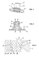
- the nut 1 shown in Fig. 1 is a single-piece formed part made of plastic.
- the nut has a body 2 having an outer contour in the shape of a six-sided prism, forming a tool engagement area 3.
- a flange 4 in the shape of a circular disc is formed that serves to support the nut 1 on a component to be fastened.
- the other end of the body 2 is provided with oblique surfaces 5 in order to facilitate the attachment of a tool.
- the nut 1 is penetrated by a bore 6 that is coaxial to the tool engagement area 3 and that has three different sections.
- a first section 7 extends through the largest portion of the body 2 and is provided with an interior thread 8 formed by a thread groove 9 that is sunk into the wall of the bore 6 and extends along a screw line.
- the interior thread 8 of the nut 1 has an outer diameter Da that is equal to the diameter of an imaginary cylinder that is coaxial to the interior thread, the surface lines of which touch the thread base of the thread groove 9.
- the core diameter Dk of the interior thread 8 is the diameter of the bore 6 in the section 7 into which the thread groove 9 is sunk.
- a cylindrical insertion section 10 is adjacent to the section 7; the inner diameter De of the insertion section is somewhat greater than the outer diameter of the interior thread 8.
- the insertion section 10 has an annular bead 11 projecting inwards, whose center lies in a plane that is radial to the axis of the bore.
- the inner diameter Dr of the annular bead 11 is less than the outer diameter Da and greater than the core diameter Dk of the interior thread 8.
- a centering section 12 follows the insertion section 10 in the direction of the flange 4; the centering section expands conically outwards and serves to center the nut 1 relative to a threaded bolt.
- Fig. 3 shows the cooperation of the annular bead 11 with the insertion end of a threaded bolt 20 inserted into the insertion section 10.
- the threaded bolt 20 has an exterior thread 21 formed by a thread rib 22 running along a screw line.
- the thread rib 22 has two flanks 23, 24 converging radially outwards in the manner of a trapezoidal thread.
- the flank angle of the flanks 23, 24 is essentially 30°, with angle bisectors lying in a plane that is perpendicular to the axis of the bolt.
- the flank 23 is facing the insertion end of the threaded bolt 20 and the flank 24 is facing away from the insertion end.
- the thread rib 22 has a radially outermost boundary surface 25 that is inclined relative to the central axis of the threaded bolt 20 such that the radial extension of the flank 23 is smaller than the radial extension of the flank 24.
- the incline of the boundary surface 25 has a magnitude such that a line G lying in the longitudinal central plane of the threaded bolt 20 and touching the boundary surface 25 would intersect the central axis of the threaded bolt 20 at an angle of approximately 30°.
- the outer diameter of the exterior thread 21 is equal to double the radius of the outermost boundary surface 25, i.e., the radius of the edge on which the boundary surface 25 meets the flank 24.
- the nut 1 and the threaded bolt 20 are adapted to one another such that the inner diameter De of the insertion section 10 of the nut 1 is greater than the outer diameter Da of the exterior thread 21.
- the inner diameter of the annular bead 11 is sufficiently less than the exterior diameter Da of the exterior thread 21 that the threaded bolt 20 with the initial section of the thread rib 22 may be pressed through the annular bead 11 into the insertion section 10 by hand but only with a certain degree of force and is able to arrive in the region between the annular bead 11 and the thread section 7.
- pre-mounting components may therefore pre-mount a component by attaching the nut to the bolt and then have their hands free to arrange the component if necessary and then to retrieve the mounting tool for screwing the pre-mounted nuts into place.
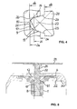
- Fig. 4 shows the profiles of the interior thread 8 of the nut 1 and the exterior thread 21 of the threaded bolt 20 in an overlapping, concentric arrangement corresponding to the engagement position of the thread upon screwing the nut 1 onto the bolt 20 but without showing the deformation of the interior thread caused by the thread rib 22 upon its penetration into the thread groove 9.
- the thread groove 9 of the nut 1 has flanks 13, 14 converging radially outwards and forming a flank angle of essentially 30° with one another.
- Di On the surface line of an imaginary concentric cylinder with a diameter Di , the straight profile of the flanks 13, 14 transitions in a continuous fashion into a round section 15 that forms the thread base of the thread groove 9.
- the center of the round section 15 forms the crest of the thread base and determines the outer diameter Da of the interior thread 8.
- the flanks 13, 14 end radially inward at the core diameter Dk .
- the flanks 13, 14 of the thread groove 9 have the same incline as the flanks 23, 24 of the thread rib 22.
- the distance between the flanks 13, 14 may be the same as or, depending on the tolerance, somewhat smaller than the distance between the flanks 23, 24.
- Fig. 4 shows a slightly smaller distance between the flanks. This causes the thread rib 22 to cause a slight compression, particularly of the flank 13, upon penetrating the thread groove 9. Space is present for material thus displaced between the core diameter Dk of the interior thread 8 and the smaller core diameter dk of the exterior thread 21.
- Displaced material may also be accommodated between the boundary surface 25 of the thread rib 22 and the round section 15 of the thread groove 9 because the thread rib 22 does not completely fill the thread groove 9 by virtue of the incline of the boundary surface 25; rather, a free hollow space 17 is present between the boundary surface 25 and the section 15 of the thread groove 9.
- the deformation of the thread groove 9 by the thread rib 22 caused by screwing the nut and bolt together generates a frictional torque by means of which the screw connection between the nut 1 and the threaded bolt 20 is secured against loosening.
- the design of the thread groove 9 and the thread rib 22 described above has the advantage that the radial load on the nut during screwing on remains relatively small, such that the risk of breakage of the nut is effectively prevented.
- the frictional torque it is possible for the frictional torque to be adapted to the desired requirements.
- the achievement of a high tightening torque is made possible by the large degree of steepness as compared to symmetrical threads and the relatively large contact surface of the flank 24 of the thread rib 22.
- Fig. 5 shows a preferred use of the screw connection described above.
- the nut 1 serves to fasten a component 30, for example, an undercarriage, to a carrier part 31 that is disposed, for example, on the carriage of a vehicle.
- the nut 1 is pre-mounted with its flange 4 in a slot 32 of the component 30.
- a threaded bolt 20 made of metal is welded onto the carrier part 31 and extends downwards from the carrier part 31. It is common for additional fastening points to be provided on the component 30 and on the carrier part 31, which are provided with a nut 1 and a threaded bolt 20 in an analogous fashion.
- the component 30 is first guided toward the carrier part 31 from below and oriented relative to the carrier part 31 in such a way that, at each of the fastening points, the threaded bolt 20 arrives in the centering section 12 of the nut 1.
- the nut 1 is centered relative to the threaded bolt 20, and the component 30 is further aligned.
- the component 30 is then pressed firmly against the component 31 at each of the fastening points, whereby the threaded bolt 20 at each fastening point penetrates into the insertion section 10 of the nut 1 until the end of the threaded bolt 20 abuts the interior thread 8 of the nut 1.
- the initial section of the thread rib 22 slides past the annular bead 11, thus holding the nut 1 and the component 31 [ sic ] it holds firmly onto the threaded bolt 20.
- the position of the component 30 may be readjusted relative to the carrier part 31 and the tool for screwing on the nuts may be retrieved.
- the nuts may be screwed onto the bolts by hand or with the aid of an automatic mounting device. The latter is favored because the tightening torque attainable with the nut according to the invention is considerably greater than the frictional torque occurring during the screwing-on process. After screwing on, the frictional torque obtained by virtue of the design of the engaging threads guarantees a strong self locking, by means of which the nut is prevented from twisting loose under operating conditions.
Landscapes
- Engineering & Computer Science (AREA)
- General Engineering & Computer Science (AREA)
- Mechanical Engineering (AREA)
- Connection Of Plates (AREA)
- Mutual Connection Of Rods And Tubes (AREA)
Abstract
Description
- The invention relates to a screw connection with a threaded bolt and a nut that may be screwed thereon, with the exterior thread of the threaded bolt and the interior thread of the nut having the same incline and the same thread angle and with a material being used for the nut that is softer, at least in the region of the interior thread, than a material used for the threaded bolt, at least in the region of the exterior thread. The invention further relates to a nut made of plastic for such a screw connection.
- A screw connection of the type mentioned above is known from
DE 198 57 225 A1 . This screw connection is used to fasten a gas pedal module to the body of a motor vehicle and is intended for automatic bolting processes. In this screw connection, the threaded bolt has a metric standard unified thread having a thread angle of 60 degrees and the interior thread of the nut, before being screwed onto the threaded bolt, has an outer diameter that is less than the outer diameter of the exterior thread of the threaded bolt. Here, the interior and exterior threads must be very dimensionally stable so that the nut is not overloaded. - German published patent application
DE 2,903,845 A1 discloses various embodiments of a screw connection with a thread that is not quite completely cut. In the embodiments described, however, the thread angle of the interior thread of the nut and the thread angle of the exterior thread of the bolt are different, so that the deformation of the thread tips of the exterior thread of the bolt does not cause jamming between the bolt and the nut. The durability of the screw connection is reduced by these different thread angles. - In addition,
FR 1,343,518 A -
JP 09-112,522 A - The object of the invention is to create a screw connection of the type mentioned at the outset in which the nut screwed onto the threaded bolt is secured against loosening by a torque, with only a relatively small amount of torque being required to screw the nut onto the threaded bolt. In addition, the nut should be prevented from breaking while being screwed on.
- This object is attained according to the invention by a screw connection having the features listed in
Claim 1. Advantageous embodiments of the screw connection are described inClaims 2 to 9; a nut that is particularly suitable for this screw connection is described inClaims 10 to 16. - The screw connection according to the invention comprises a threaded bolt and a nut to be screwed thereon, with the threaded bolt being provided with an exterior thread provided with a thread rib in the style of a trapeze thread having flanks converging radially outwards that are straight in profile and a radially exterior boundary surface located therebetween, with the nut having a bore provided over at least part of its length with an interior thread formed by a thread groove, with the thread groove having flanks converging radially outwards that are straight in profile, which transition radially outwards in a continuous fashion into a round section forming the thread base of the thread groove, with a material being used for the nut that is softer, at least in the region of the interior thread, than a material used for the threaded bolt, at least in the region of its exterior thread, with outer diameter of the exterior thread of the threaded bolt being greater than the diameter of an imaginary coaxial cylinder whose outer surface separates the flank sections of the interior thread of the nut before being screwed onto the threaded bolt from the round section forming the thread groove, such that, when the nut is screwed onto the threaded bolt, the exterior thread of the threaded bolt displaces material in the region of the thread base of the interior thread of the nut, with an open space being kept free between the radially outermost boundary surface of the thread rib of the threaded bolt and the thread base of the thread groove of the nut for accommodating displaced material. Here, the outer diameter of the interior thread of the nut is the diameter of an imaginary cylinder that is coaxial to the interior thread and whose surface lines touch the thread base of the interior thread and the outer diameter of the exterior thread of the threaded bolt is equal to double the greatest radius of the radially outermost boundary surface of the thread rib of the exterior thread.
- The screw connection according to the invention allows an easy and reliable bolting and attains a high degree of self-locking momentum after bolting. The radial load on the nut remains relatively small and the shape of the interior thread reduces the risk of breakage to the nut.
- In one embodiment of the screw connection, the radially outermost boundary surface of the thread rib of the exterior thread of the threaded bolt may be part of a cylindrical surface, with the outer diameter of the exterior thread of the threaded bolt being smaller than the outer diameter of the interior thread of the nut.
- However, a design of the screw connection is preferred in which the radially outermost boundary surface of the thread rib of the exterior thread of the threaded bolt is inclined relative to the central axis of the threaded bolt such that the outer diameter of the thread flank facing the threaded end is smaller than the outer diameter of the thread flank facing away from the threaded end, with the outer diameter of the interior thread of the nut being approximately equal to or less than the outer diameter of the exterior thread of the threaded bolt. Here, the effective load-bearing flanks of the nut and threaded bolt have a greater width, such that the screw connection has a greater resilience. It has been shown to be advantageous for the radially outermost boundary surface of the thread rib to be inclined such that a radial line touching the radially outermost boundary surface would intersect with the central axis of the threaded bolt at an angle of approximately 30 degrees.
- According to another recommendation of the invention, the diameter of an imaginary cylinder that intersects with the inclined radially outermost boundary surface of the thread rib in the center may be smaller than the outer diameter of the interior thread of the nut. This results in a hollow space between the radially outermost boundary surface and the thread base of the interior thread of the bolt that is able to accommodate material displaced by the thread rib. Thus, the nut is prevented from being locked too tightly while being screwed on, and the nut is prevented from bearing too great a load.
- In addition, provision may be made for the interior thread of the nut to have an original core diameter before the nut is screwed onto the threaded bolt that is greater than a core diameter of the exterior thread of the threaded bolt, such that at least a portion of the displaced material may be accommodated in a region present between the original core diameter of the nut and the core diameter of the bolt.
- According to an additional recommendation of the invention, the screw connection comprises a nut made of plastic having a bore provided over at least a portion of its length with an interior thread formed by a thread groove, with the thread groove having a thread profile that has straight flank sections converging radially outward in the manner of a trapezoidal thread which transition radially outwards in a continuous fashion into a round section forming the thread base of the thread groove. Such a nut is break-proof and may be produced as one piece in a simple and cost-effective manner by means of master forming. In order to achieve greater fastening torques, the flank angle of the flank sections of the nut may be 25 to 35 degrees, particularly 30 degrees.
- It is particularly advantageous for the bore of the nut to have a threaded end having an insertion section that has an inner diameter sized such that the nut, along with the insertion section, may be placed axially onto a threaded bolt having the exterior thread associated with the interior thread of the nut, with a locking projection being provided in the insertion section having a shape and size such that the nut may be held on the exterior thread of a threaded bolt by a locking retention. The locking projection may be an annular bead having a central plane that is radial to the bore axis. This has the advantage that the nut and the threaded bolt may be locked in any desired rotational position.
- In order to facilitate the combination of the nut with the threaded bolt, the nut may additionally have a centering section expanding conically outward that follows the insertion section outwardly.
- The invention shall be described in greater detail below with reference to one exemplary embodiment, which is shown in the drawings. Shown are:
- Fig. 1
- a perspective view of a nut according to the invention,
- Fig. 2
- a cross section of the nut according to
Fig. 1 , - Fig. 3
- an enlarged section of the threaded end of the nut according to
Fig. 1 with the threaded end of the threaded bolt disposed therein, - Fig. 4
- an enlarged section of the engagement region between the interior thread of the nut according to
Fig. 1 and the exterior thread of the associated threaded bolt, - Fig. 5
- an attachment of two parts using a screw connection according to the invention.
- The
nut 1 shown inFig. 1 is a single-piece formed part made of plastic. The nut has abody 2 having an outer contour in the shape of a six-sided prism, forming atool engagement area 3. At one end of thebody 2, aflange 4 in the shape of a circular disc is formed that serves to support thenut 1 on a component to be fastened. The other end of thebody 2 is provided withoblique surfaces 5 in order to facilitate the attachment of a tool. - As may be seen from
Fig. 2 , thenut 1 is penetrated by abore 6 that is coaxial to thetool engagement area 3 and that has three different sections. Afirst section 7 extends through the largest portion of thebody 2 and is provided with aninterior thread 8 formed by a thread groove 9 that is sunk into the wall of thebore 6 and extends along a screw line. Theinterior thread 8 of thenut 1 has an outer diameter Da that is equal to the diameter of an imaginary cylinder that is coaxial to the interior thread, the surface lines of which touch the thread base of the thread groove 9. The core diameter Dk of theinterior thread 8 is the diameter of thebore 6 in thesection 7 into which the thread groove 9 is sunk. - On the side facing the
flange 4, acylindrical insertion section 10 is adjacent to thesection 7; the inner diameter De of the insertion section is somewhat greater than the outer diameter of theinterior thread 8. At a distance x from thesection 7, theinsertion section 10 has anannular bead 11 projecting inwards, whose center lies in a plane that is radial to the axis of the bore. The inner diameter Dr of theannular bead 11 is less than the outer diameter Da and greater than the core diameter Dk of theinterior thread 8. - A
centering section 12 follows theinsertion section 10 in the direction of theflange 4; the centering section expands conically outwards and serves to center thenut 1 relative to a threaded bolt. -
Fig. 3 shows the cooperation of theannular bead 11 with the insertion end of a threadedbolt 20 inserted into theinsertion section 10. The threadedbolt 20 has anexterior thread 21 formed by athread rib 22 running along a screw line. Thethread rib 22 has twoflanks flanks flank 23 is facing the insertion end of the threadedbolt 20 and theflank 24 is facing away from the insertion end. Deviating from a conventional and standardized trapezoidal thread, thethread rib 22 has a radiallyoutermost boundary surface 25 that is inclined relative to the central axis of the threadedbolt 20 such that the radial extension of theflank 23 is smaller than the radial extension of theflank 24. The incline of theboundary surface 25 has a magnitude such that a line G lying in the longitudinal central plane of the threadedbolt 20 and touching theboundary surface 25 would intersect the central axis of the threadedbolt 20 at an angle of approximately 30°. As a result of this design, the outer diameter of theexterior thread 21 is equal to double the radius of theoutermost boundary surface 25, i.e., the radius of the edge on which theboundary surface 25 meets theflank 24. - The
nut 1 and the threadedbolt 20 are adapted to one another such that the inner diameter De of theinsertion section 10 of thenut 1 is greater than the outer diameter Da of theexterior thread 21. In contrast, the inner diameter of theannular bead 11 is sufficiently less than the exterior diameter Da of theexterior thread 21 that the threadedbolt 20 with the initial section of thethread rib 22 may be pressed through theannular bead 11 into theinsertion section 10 by hand but only with a certain degree of force and is able to arrive in the region between theannular bead 11 and thethread section 7. Pressing the bolt in is facilitated by the incline of theboundary surface 25 because theannular bead 11 comes into contact with theboundary surface 25 upon the threadedbolt 20 being pressed in and is able to slide away via said boundary surface. However, if a user desires to remove thenut 1 from the threadedbolt 20 in the opposite direction, thesteep flank 24 with its sharp edge comes into contact with theannular bead 11 on its outermost edge, such that a considerably greater amount of force is necessary to remove thenut 1 from the end of the threadedbolt 20. Theannular bead 11 in theinsertion section 10 therefore allows a connection between thenut 1 and the threadedbolt 20 by axial insertion and without the need for a screwing process. Although the retaining force of the inserted connection is considerably less than the retaining force of the screw connection, it is still sufficient for pre-mounting components to be fastened using the nut by merely attaching the nut, and is even able to hold the nut in place on the threaded bolt for overhead mounting. Persons mounting components may therefore pre-mount a component by attaching the nut to the bolt and then have their hands free to arrange the component if necessary and then to retrieve the mounting tool for screwing the pre-mounted nuts into place. -
Fig. 4 shows the profiles of theinterior thread 8 of thenut 1 and theexterior thread 21 of the threadedbolt 20 in an overlapping, concentric arrangement corresponding to the engagement position of the thread upon screwing thenut 1 onto thebolt 20 but without showing the deformation of the interior thread caused by thethread rib 22 upon its penetration into the thread groove 9. The thread groove 9 of thenut 1 hasflanks flanks interior thread 8. Theflanks - The
flanks flanks thread rib 22. The distance between theflanks flanks Fig. 4 shows a slightly smaller distance between the flanks. This causes thethread rib 22 to cause a slight compression, particularly of theflank 13, upon penetrating the thread groove 9. Space is present for material thus displaced between the core diameter Dk of theinterior thread 8 and the smaller core diameter dk of theexterior thread 21. Displaced material may also be accommodated between theboundary surface 25 of thethread rib 22 and the round section 15 of the thread groove 9 because thethread rib 22 does not completely fill the thread groove 9 by virtue of the incline of theboundary surface 25; rather, a freehollow space 17 is present between theboundary surface 25 and the section 15 of the thread groove 9. - The outer diameter da of the
thread rib 22, which is determined by theedge 26 formed by theflank 24 and theboundary surface 25, has approximately the same size as the outer diameter Da of the thread groove 9. Upon screwing together the nut and bolt, thethread rib 22 therefore burrows into the region of the section 15 adjacent to theflank 14; material of thenut 1 displaced thereby may also be accommodated by thehollow space 17. - The deformation of the thread groove 9 by the
thread rib 22 caused by screwing the nut and bolt together generates a frictional torque by means of which the screw connection between thenut 1 and the threadedbolt 20 is secured against loosening. The design of the thread groove 9 and thethread rib 22 described above has the advantage that the radial load on the nut during screwing on remains relatively small, such that the risk of breakage of the nut is effectively prevented. Moreover, by changing the diameter Di and the outer diameter Da of the thread groove, it is possible for the frictional torque to be adapted to the desired requirements. The achievement of a high tightening torque is made possible by the large degree of steepness as compared to symmetrical threads and the relatively large contact surface of theflank 24 of thethread rib 22. -
Fig. 5 shows a preferred use of the screw connection described above. Here, thenut 1 serves to fasten a component 30, for example, an undercarriage, to acarrier part 31 that is disposed, for example, on the carriage of a vehicle. To this end, thenut 1 is pre-mounted with itsflange 4 in a slot 32 of the component 30. A threadedbolt 20 made of metal is welded onto thecarrier part 31 and extends downwards from thecarrier part 31. It is common for additional fastening points to be provided on the component 30 and on thecarrier part 31, which are provided with anut 1 and a threadedbolt 20 in an analogous fashion. - For the mounting, the component 30 is first guided toward the
carrier part 31 from below and oriented relative to thecarrier part 31 in such a way that, at each of the fastening points, the threadedbolt 20 arrives in the centeringsection 12 of thenut 1. By continuing to move the component 30 closer to thecarrier part 31, thenut 1 is centered relative to the threadedbolt 20, and the component 30 is further aligned. The component 30 is then pressed firmly against thecomponent 31 at each of the fastening points, whereby the threadedbolt 20 at each fastening point penetrates into theinsertion section 10 of thenut 1 until the end of the threadedbolt 20 abuts theinterior thread 8 of thenut 1. In this process, the initial section of thethread rib 22 slides past theannular bead 11, thus holding thenut 1 and the component 31 [sic] it holds firmly onto the threadedbolt 20. In the pre-mounting position thus attained, the position of the component 30 may be readjusted relative to thecarrier part 31 and the tool for screwing on the nuts may be retrieved. The nuts may be screwed onto the bolts by hand or with the aid of an automatic mounting device. The latter is favored because the tightening torque attainable with the nut according to the invention is considerably greater than the frictional torque occurring during the screwing-on process. After screwing on, the frictional torque obtained by virtue of the design of the engaging threads guarantees a strong self locking, by means of which the nut is prevented from twisting loose under operating conditions.
Claims (16)
- A screw connection having a threaded bolt (20) and a nut (1) that may be screwed thereon, wherein
the threaded bolt (20) is provided with an exterior thread (21) comprising a thread rib (22) in the manner of a trapezoidal thread having flanks (23, 24) that are straight in profile and that converge radially outward and a radially outermost boundary surface (25) located therebetween,
the nut (1) has a bore (6) provided on at least part of its length with an interior thread (8) formed by a thread groove (9), with the thread groove (9) having flank sections (13, 14) that are straight in profile and that converge radially outward in the manner of a trapezoidal thread, said flank sections transitioning radially outward in a continuous manner into a round section (15) forming the thread base of the thread groove (9),
a material is used for the nut (1) that is softer, at least in the region of the interior thread (8), than a material used for the threaded bolt (20), at least in the region of the exterior thread (21),
the exterior thread (21) of the threaded bolt (20) and the interior thread (8) of the nut (1) have an equal incline and an equal flank angle,
the outer diameter (da) of the exterior thread of the threaded bolt (20) is greater than the diameter (Di) of an imaginary cylinder whose surface separates the flank sections (13, 14) of the interior thread (8) of the nut (1) before being screwed onto the threaded bolt (20) from the round section (15) forming the thread base of the thread groove (9), such that, upon the nut (1) being screwed onto the threaded bolt (20), the exterior thread (21) of the threaded bolt (20) displaces material in the region of the thread base of the interior thread (8) of the nut (1),
a hollow space (17) is kept free between the radially outermost boundary surface (25) of the thread rib (22) of the threaded bolt (20) and the thread base of the thread groove (9) of the nut (1) in order to accommodate displaced material. - The screw connection according to Claim 1, characterized in that the radially outermost boundary surface of the thread rib of the exterior thread of the threaded bolt is part of a cylindrical surface and the outer diameter of the exterior thread is less than the outer diameter of the interior thread of the nut.
- The screw connection according to Claim 1, characterized in that the radially outermost boundary surface (25) of the thread rib (22) of the exterior thread (21) of the threaded bolt (20) is inclined relative to the central axis of the threaded bolt (20) in such a way that the outer diameter of the thread flank (23) facing the threaded end is less than the outer diameter of the thread flank (24) facing away from the threaded end.
- The screw connection according to the previous Claim, characterized in that a radial line touching the radially outermost boundary surface (25) of the thread rib (22) would intersect with the central axis of the threaded bolt (20) at an angle of approximately 30 degrees.
- The screw connection according to the previous Claim, characterized in that the diameter of an imaginary cylinder whose surface line intersects the radially outermost boundary surface (25) of the thread rib (22) in the center is less than the outer diameter of the interior thread (8) of the nut (1 ).
- The screw connection according to any one of the previous Claims, characterized in that the flank angle of the interior thread (8) and of the exterior thread (21) is 25 to 35 degrees, in particular 30 degrees.
- The screw connection according to any one of Claims 2 to 6, characterized in that the outer diameter of the interior thread (8) of the nut (1) is approximately equal to or less than the outer diameter of the exterior thread (21) of the threaded bolt (20).
- The screw connection according to any one of the previous Claims, characterized in that, before screwing the nut (1) onto the threaded bolt (20), the interior thread (21) [sic] of the nut (1) has an original core diameter (Dk) that is greater than a core diameter (dk) of the exterior thread (21) of the threaded bolt (20), such that at least part of the displaced material may be accommodated in a region that is present before bolting between the original core diameter (Dk) of the nut (1) and the core diameter (dk) of the threaded bolt (20).
- The screw connection according to any one of the previous Claims, characterized in that the threaded bolt (20) is made of metal and the nut (1) is made of plastic.
- A nut made of plastic for a screw connection according to one of the previous Claims, characterized by a bore (6) provided at least over part of its length with an interior thread (8) formed by a thread groove (9), with the thread groove (9) having a thread profile that has straight flank sections (13, 14) converging radially outward that transition radially outward in a continuous manner into a round section (15) forming the thread base of the thread groove.
- The nut according to Claim 10, characterized in that the flank angle of the flank sections (13, 14) is 25 to 35 degrees, in particular 30 degrees.
- The nut according to any one of Claims 10 or 11, characterized in that the bore (6) comprises a threaded end having an insertion section (10) having an inner diameter of such a size that the nut (1) may be placed with its insertion section (10) axially onto a threaded bolt having an exterior thread (21) associated with the interior thread (8) of the nut (1), and in that a locking projection is provided in the insertion section (10) having a shape and size such that the nut (1) may be held in place by locking attachment on the exterior thread (21) of a threaded bolt (20).
- The nut according to Claim 12, characterized in that the locking projection is an annular bead (11) having a central plane that is radial relative to the axis of the bore.
- The nut according to any one of Claims 12 or 13, characterized by a centering section (12) expanding conically outward that follows the insertion section (10) outwardly.
- The nut according to any one of Claims 10 to 14, characterized by a tool engagement area (3) formed on its outer circumference that is coaxial to the interior thread (8).
- The nut according to any one of Claims 10 to 15, characterized by a saucer-shaped flange (4) disposed on the threaded end.
Applications Claiming Priority (1)
| Application Number | Priority Date | Filing Date | Title |
|---|---|---|---|
| DE200910029403 DE102009029403A1 (en) | 2009-09-11 | 2009-09-11 | Screw connection with threaded bolt and nut |
Publications (2)
| Publication Number | Publication Date |
|---|---|
| EP2295822A1 true EP2295822A1 (en) | 2011-03-16 |
| EP2295822B1 EP2295822B1 (en) | 2014-06-11 |
Family
ID=43382396
Family Applications (1)
| Application Number | Title | Priority Date | Filing Date |
|---|---|---|---|
| EP20100174275 Active EP2295822B1 (en) | 2009-09-11 | 2010-08-27 | Screw connection with threaded bolt and nut |
Country Status (5)
| Country | Link |
|---|---|
| EP (1) | EP2295822B1 (en) |
| JP (1) | JP5643582B2 (en) |
| CN (1) | CN102022408B (en) |
| DE (1) | DE102009029403A1 (en) |
| ES (1) | ES2485290T3 (en) |
Cited By (4)
| Publication number | Priority date | Publication date | Assignee | Title |
|---|---|---|---|---|
| WO2018011390A1 (en) * | 2016-07-15 | 2018-01-18 | Newfrey Llc | Joining element, nut and fastening system |
| CN114060388A (en) * | 2020-08-07 | 2022-02-18 | 舍弗勒技术股份两合公司 | Lock nut and method for producing and assembling a lock nut |
| CN114623143A (en) * | 2022-04-02 | 2022-06-14 | 聂俊斌 | Bolt and nut assembly with strong stability for mechanical configuration |
| CN115715433A (en) * | 2020-11-13 | 2023-02-24 | 株式会社Lg新能源 | Battery pack, electronic device, vehicle, and battery management system module |
Families Citing this family (6)
| Publication number | Priority date | Publication date | Assignee | Title |
|---|---|---|---|---|
| DE102013100849A1 (en) * | 2013-01-29 | 2014-07-31 | Newfrey Llc | Method for injection molding a fastener and fastener |
| JP6699300B2 (en) * | 2016-04-04 | 2020-05-27 | 日本精工株式会社 | Lubricant supply parts mounting structure |
| JP6943805B2 (en) * | 2018-04-10 | 2021-10-06 | パラマウントベッド株式会社 | Manifold |
| US11542005B2 (en) | 2019-01-29 | 2023-01-03 | Goodrich Corporation | Quick-connect fittings for convertible cargo handling assemblies |
| US11535359B2 (en) * | 2019-01-29 | 2022-12-27 | Goodrich Corporation | Flexible and simple turnaround cargo handling assemblies |
| CN114001065A (en) * | 2021-11-27 | 2022-02-01 | 丁安琦 | Connecting structure of top cover and oil cylinder of hydraulic oil cylinder |
Citations (5)
| Publication number | Priority date | Publication date | Assignee | Title |
|---|---|---|---|---|
| FR1343518A (en) | 1962-06-07 | 1963-11-22 | Method for obtaining self-tightening of a nut on a screw | |
| DE2247289A1 (en) * | 1972-09-27 | 1974-03-28 | Siemens Ag | DIRECT OR INTERMEDIATE SCREW CONNECTION TO A PLASTIC PART |
| DE2903845A1 (en) | 1978-02-10 | 1979-08-16 | Holmes Horace D | SCREW CONNECTION |
| JPH09112522A (en) | 1995-10-12 | 1997-05-02 | Pop Rivet Fastener Kk | Dump bolt |
| DE19857225A1 (en) | 1998-12-11 | 2000-06-15 | Bosch Gmbh Robert | Screw connection for an accelerator pedal module of a motor vehicle |
Family Cites Families (10)
| Publication number | Priority date | Publication date | Assignee | Title |
|---|---|---|---|---|
| DE7925469U1 (en) * | 1979-09-07 | 1979-12-20 | Tucker Gmbh, 6300 Giessen | Welding pin for holding material |
| JPS6326410A (en) * | 1986-07-16 | 1988-02-04 | 株式会社 冨士精密製作所 | Lock nut |
| JPH09166120A (en) * | 1995-12-15 | 1997-06-24 | Inax Corp | Nut made of synthetic resin |
| JP4172680B2 (en) * | 2001-06-22 | 2008-10-29 | 株式会社住友金属小倉 | High strength bolt |
| JP2003166519A (en) * | 2001-12-03 | 2003-06-13 | Maruzen Byora:Kk | Plastic locking nut |
| JP3871137B2 (en) * | 2003-10-23 | 2007-01-24 | ビッグアルファ株式会社 | Internal thread member, external thread member and internal thread machining tool |
| ES2246119B1 (en) * | 2004-01-26 | 2007-03-16 | I.T.W. España, S.A. | NUT FASTENING FAST. |
| JP4100692B2 (en) * | 2004-08-23 | 2008-06-11 | 株式会社ユニオン精密 | Tightening screw |
| CN201053428Y (en) * | 2007-06-13 | 2008-04-30 | 汕头市濠江区工艺行业协会 | Screw bolt and nut fastener convenient for mounting |
| TWI400394B (en) * | 2009-02-12 | 2013-07-01 | Yugen Kaisha Art Screw | Fastening members and fastening structures |
-
2009
- 2009-09-11 DE DE200910029403 patent/DE102009029403A1/en not_active Withdrawn
-
2010
- 2010-08-27 EP EP20100174275 patent/EP2295822B1/en active Active
- 2010-08-27 ES ES10174275.7T patent/ES2485290T3/en active Active
- 2010-09-09 JP JP2010201587A patent/JP5643582B2/en not_active Expired - Fee Related
- 2010-09-10 CN CN201010284151.6A patent/CN102022408B/en not_active Expired - Fee Related
Patent Citations (5)
| Publication number | Priority date | Publication date | Assignee | Title |
|---|---|---|---|---|
| FR1343518A (en) | 1962-06-07 | 1963-11-22 | Method for obtaining self-tightening of a nut on a screw | |
| DE2247289A1 (en) * | 1972-09-27 | 1974-03-28 | Siemens Ag | DIRECT OR INTERMEDIATE SCREW CONNECTION TO A PLASTIC PART |
| DE2903845A1 (en) | 1978-02-10 | 1979-08-16 | Holmes Horace D | SCREW CONNECTION |
| JPH09112522A (en) | 1995-10-12 | 1997-05-02 | Pop Rivet Fastener Kk | Dump bolt |
| DE19857225A1 (en) | 1998-12-11 | 2000-06-15 | Bosch Gmbh Robert | Screw connection for an accelerator pedal module of a motor vehicle |
Cited By (4)
| Publication number | Priority date | Publication date | Assignee | Title |
|---|---|---|---|---|
| WO2018011390A1 (en) * | 2016-07-15 | 2018-01-18 | Newfrey Llc | Joining element, nut and fastening system |
| CN114060388A (en) * | 2020-08-07 | 2022-02-18 | 舍弗勒技术股份两合公司 | Lock nut and method for producing and assembling a lock nut |
| CN115715433A (en) * | 2020-11-13 | 2023-02-24 | 株式会社Lg新能源 | Battery pack, electronic device, vehicle, and battery management system module |
| CN114623143A (en) * | 2022-04-02 | 2022-06-14 | 聂俊斌 | Bolt and nut assembly with strong stability for mechanical configuration |
Also Published As
| Publication number | Publication date |
|---|---|
| JP2011058628A (en) | 2011-03-24 |
| CN102022408A (en) | 2011-04-20 |
| DE102009029403A1 (en) | 2011-03-24 |
| EP2295822B1 (en) | 2014-06-11 |
| CN102022408B (en) | 2014-10-15 |
| JP5643582B2 (en) | 2014-12-17 |
| ES2485290T3 (en) | 2014-08-13 |
Similar Documents
| Publication | Publication Date | Title |
|---|---|---|
| EP2295822B1 (en) | Screw connection with threaded bolt and nut | |
| US6758646B1 (en) | Structure for preventing loosening of threaded fasteners | |
| US20020028121A1 (en) | Fastening system | |
| US9022709B2 (en) | Screw with anti-loosening means | |
| JP4710089B1 (en) | Locking washer and locking fastener using the same | |
| US20080219801A1 (en) | Screw Fastener | |
| KR20180036727A (en) | Threaded fasteners | |
| US5302066A (en) | Locking fastener | |
| JP2008223937A (en) | Fastener | |
| JPH02118208A (en) | Assembly of clamper and holding ring | |
| WO2015118702A1 (en) | Bolt provided with locking function | |
| KR20100102681A (en) | Threaded insert and vehicle component | |
| WO2012070272A1 (en) | Bolt | |
| US3358551A (en) | Fasteners | |
| KR20160027006A (en) | Fastening element and fastening assembly | |
| CN110159640A (en) | A kind of anti-loosening screw nut assembly | |
| JP2012137174A (en) | Loosening prevention bolt | |
| US6688823B2 (en) | Fastening position adjustable bolt and mount construction of members using the same | |
| EP2034193A2 (en) | Fastening system for fastening components, in particular for motor vehicles | |
| JP5735905B2 (en) | Retaining tool, fastening method and fastening structure | |
| JP5556997B2 (en) | Friction fastener | |
| JP3232253U (en) | Grip nut | |
| AU2013339553B2 (en) | Screw connection arrangement | |
| JP4198724B2 (en) | Screw locking structure | |
| US20220205471A1 (en) | Locking feature for a fastener |
Legal Events
| Date | Code | Title | Description |
|---|---|---|---|
| PUAI | Public reference made under article 153(3) epc to a published international application that has entered the european phase |
Free format text: ORIGINAL CODE: 0009012 |
|
| AK | Designated contracting states |
Kind code of ref document: A1 Designated state(s): AL AT BE BG CH CY CZ DE DK EE ES FI FR GB GR HR HU IE IS IT LI LT LU LV MC MK MT NL NO PL PT RO SE SI SK SM TR |
|
| AX | Request for extension of the european patent |
Extension state: BA ME RS |
|
| 17P | Request for examination filed |
Effective date: 20110715 |
|
| RIC1 | Information provided on ipc code assigned before grant |
Ipc: F16B 37/00 20060101AFI20131211BHEP |
|
| GRAP | Despatch of communication of intention to grant a patent |
Free format text: ORIGINAL CODE: EPIDOSNIGR1 |
|
| INTG | Intention to grant announced |
Effective date: 20140123 |
|
| GRAS | Grant fee paid |
Free format text: ORIGINAL CODE: EPIDOSNIGR3 |
|
| GRAA | (expected) grant |
Free format text: ORIGINAL CODE: 0009210 |
|
| AK | Designated contracting states |
Kind code of ref document: B1 Designated state(s): AL AT BE BG CH CY CZ DE DK EE ES FI FR GB GR HR HU IE IS IT LI LT LU LV MC MK MT NL NO PL PT RO SE SI SK SM TR |
|
| REG | Reference to a national code |
Ref country code: GB Ref legal event code: FG4D |
|
| REG | Reference to a national code |
Ref country code: CH Ref legal event code: EP |
|
| REG | Reference to a national code |
Ref country code: IE Ref legal event code: FG4D |
|
| REG | Reference to a national code |
Ref country code: AT Ref legal event code: REF Ref document number: 672413 Country of ref document: AT Kind code of ref document: T Effective date: 20140715 |
|
| REG | Reference to a national code |
Ref country code: DE Ref legal event code: R096 Ref document number: 602010016593 Country of ref document: DE Effective date: 20140724 |
|
| REG | Reference to a national code |
Ref country code: ES Ref legal event code: FG2A Ref document number: 2485290 Country of ref document: ES Kind code of ref document: T3 Effective date: 20140813 |
|
| PG25 | Lapsed in a contracting state [announced via postgrant information from national office to epo] |
Ref country code: LT Free format text: LAPSE BECAUSE OF FAILURE TO SUBMIT A TRANSLATION OF THE DESCRIPTION OR TO PAY THE FEE WITHIN THE PRESCRIBED TIME-LIMIT Effective date: 20140611 Ref country code: NO Free format text: LAPSE BECAUSE OF FAILURE TO SUBMIT A TRANSLATION OF THE DESCRIPTION OR TO PAY THE FEE WITHIN THE PRESCRIBED TIME-LIMIT Effective date: 20140911 Ref country code: GR Free format text: LAPSE BECAUSE OF FAILURE TO SUBMIT A TRANSLATION OF THE DESCRIPTION OR TO PAY THE FEE WITHIN THE PRESCRIBED TIME-LIMIT Effective date: 20140912 Ref country code: FI Free format text: LAPSE BECAUSE OF FAILURE TO SUBMIT A TRANSLATION OF THE DESCRIPTION OR TO PAY THE FEE WITHIN THE PRESCRIBED TIME-LIMIT Effective date: 20140611 |
|
| REG | Reference to a national code |
Ref country code: NL Ref legal event code: VDEP Effective date: 20140611 |
|
| REG | Reference to a national code |
Ref country code: AT Ref legal event code: MK05 Ref document number: 672413 Country of ref document: AT Kind code of ref document: T Effective date: 20140611 |
|
| REG | Reference to a national code |
Ref country code: LT Ref legal event code: MG4D |
|
| PG25 | Lapsed in a contracting state [announced via postgrant information from national office to epo] |
Ref country code: LV Free format text: LAPSE BECAUSE OF FAILURE TO SUBMIT A TRANSLATION OF THE DESCRIPTION OR TO PAY THE FEE WITHIN THE PRESCRIBED TIME-LIMIT Effective date: 20140611 Ref country code: SE Free format text: LAPSE BECAUSE OF FAILURE TO SUBMIT A TRANSLATION OF THE DESCRIPTION OR TO PAY THE FEE WITHIN THE PRESCRIBED TIME-LIMIT Effective date: 20140611 Ref country code: HR Free format text: LAPSE BECAUSE OF FAILURE TO SUBMIT A TRANSLATION OF THE DESCRIPTION OR TO PAY THE FEE WITHIN THE PRESCRIBED TIME-LIMIT Effective date: 20140611 |
|
| PGFP | Annual fee paid to national office [announced via postgrant information from national office to epo] |
Ref country code: ES Payment date: 20140826 Year of fee payment: 5 |
|
| PGFP | Annual fee paid to national office [announced via postgrant information from national office to epo] |
Ref country code: IT Payment date: 20140822 Year of fee payment: 5 |
|
| PG25 | Lapsed in a contracting state [announced via postgrant information from national office to epo] |
Ref country code: CZ Free format text: LAPSE BECAUSE OF FAILURE TO SUBMIT A TRANSLATION OF THE DESCRIPTION OR TO PAY THE FEE WITHIN THE PRESCRIBED TIME-LIMIT Effective date: 20140611 Ref country code: RO Free format text: LAPSE BECAUSE OF FAILURE TO SUBMIT A TRANSLATION OF THE DESCRIPTION OR TO PAY THE FEE WITHIN THE PRESCRIBED TIME-LIMIT Effective date: 20140611 Ref country code: EE Free format text: LAPSE BECAUSE OF FAILURE TO SUBMIT A TRANSLATION OF THE DESCRIPTION OR TO PAY THE FEE WITHIN THE PRESCRIBED TIME-LIMIT Effective date: 20140611 Ref country code: PT Free format text: LAPSE BECAUSE OF FAILURE TO SUBMIT A TRANSLATION OF THE DESCRIPTION OR TO PAY THE FEE WITHIN THE PRESCRIBED TIME-LIMIT Effective date: 20141013 Ref country code: SK Free format text: LAPSE BECAUSE OF FAILURE TO SUBMIT A TRANSLATION OF THE DESCRIPTION OR TO PAY THE FEE WITHIN THE PRESCRIBED TIME-LIMIT Effective date: 20140611 |
|
| PG25 | Lapsed in a contracting state [announced via postgrant information from national office to epo] |
Ref country code: AT Free format text: LAPSE BECAUSE OF FAILURE TO SUBMIT A TRANSLATION OF THE DESCRIPTION OR TO PAY THE FEE WITHIN THE PRESCRIBED TIME-LIMIT Effective date: 20140611 Ref country code: NL Free format text: LAPSE BECAUSE OF FAILURE TO SUBMIT A TRANSLATION OF THE DESCRIPTION OR TO PAY THE FEE WITHIN THE PRESCRIBED TIME-LIMIT Effective date: 20140611 Ref country code: IS Free format text: LAPSE BECAUSE OF FAILURE TO SUBMIT A TRANSLATION OF THE DESCRIPTION OR TO PAY THE FEE WITHIN THE PRESCRIBED TIME-LIMIT Effective date: 20141011 Ref country code: PL Free format text: LAPSE BECAUSE OF FAILURE TO SUBMIT A TRANSLATION OF THE DESCRIPTION OR TO PAY THE FEE WITHIN THE PRESCRIBED TIME-LIMIT Effective date: 20140611 |
|
| REG | Reference to a national code |
Ref country code: DE Ref legal event code: R097 Ref document number: 602010016593 Country of ref document: DE |
|
| PG25 | Lapsed in a contracting state [announced via postgrant information from national office to epo] |
Ref country code: MC Free format text: LAPSE BECAUSE OF FAILURE TO SUBMIT A TRANSLATION OF THE DESCRIPTION OR TO PAY THE FEE WITHIN THE PRESCRIBED TIME-LIMIT Effective date: 20140611 Ref country code: LU Free format text: LAPSE BECAUSE OF FAILURE TO SUBMIT A TRANSLATION OF THE DESCRIPTION OR TO PAY THE FEE WITHIN THE PRESCRIBED TIME-LIMIT Effective date: 20140827 |
|
| REG | Reference to a national code |
Ref country code: CH Ref legal event code: PL |
|
| PLBE | No opposition filed within time limit |
Free format text: ORIGINAL CODE: 0009261 |
|
| STAA | Information on the status of an ep patent application or granted ep patent |
Free format text: STATUS: NO OPPOSITION FILED WITHIN TIME LIMIT |
|
| PG25 | Lapsed in a contracting state [announced via postgrant information from national office to epo] |
Ref country code: BE Free format text: LAPSE BECAUSE OF NON-PAYMENT OF DUE FEES Effective date: 20140831 Ref country code: CH Free format text: LAPSE BECAUSE OF NON-PAYMENT OF DUE FEES Effective date: 20140831 Ref country code: LI Free format text: LAPSE BECAUSE OF NON-PAYMENT OF DUE FEES Effective date: 20140831 Ref country code: DK Free format text: LAPSE BECAUSE OF FAILURE TO SUBMIT A TRANSLATION OF THE DESCRIPTION OR TO PAY THE FEE WITHIN THE PRESCRIBED TIME-LIMIT Effective date: 20140611 |
|
| 26N | No opposition filed |
Effective date: 20150312 |
|
| REG | Reference to a national code |
Ref country code: IE Ref legal event code: MM4A |
|
| REG | Reference to a national code |
Ref country code: DE Ref legal event code: R097 Ref document number: 602010016593 Country of ref document: DE Effective date: 20150312 |
|
| PG25 | Lapsed in a contracting state [announced via postgrant information from national office to epo] |
Ref country code: BE Free format text: LAPSE BECAUSE OF FAILURE TO SUBMIT A TRANSLATION OF THE DESCRIPTION OR TO PAY THE FEE WITHIN THE PRESCRIBED TIME-LIMIT Effective date: 20140611 |
|
| PG25 | Lapsed in a contracting state [announced via postgrant information from national office to epo] |
Ref country code: SI Free format text: LAPSE BECAUSE OF FAILURE TO SUBMIT A TRANSLATION OF THE DESCRIPTION OR TO PAY THE FEE WITHIN THE PRESCRIBED TIME-LIMIT Effective date: 20140611 |
|
| PG25 | Lapsed in a contracting state [announced via postgrant information from national office to epo] |
Ref country code: IE Free format text: LAPSE BECAUSE OF NON-PAYMENT OF DUE FEES Effective date: 20140827 |
|
| PG25 | Lapsed in a contracting state [announced via postgrant information from national office to epo] |
Ref country code: IT Free format text: LAPSE BECAUSE OF NON-PAYMENT OF DUE FEES Effective date: 20150827 Ref country code: SM Free format text: LAPSE BECAUSE OF FAILURE TO SUBMIT A TRANSLATION OF THE DESCRIPTION OR TO PAY THE FEE WITHIN THE PRESCRIBED TIME-LIMIT Effective date: 20140611 |
|
| PG25 | Lapsed in a contracting state [announced via postgrant information from national office to epo] |
Ref country code: MT Free format text: LAPSE BECAUSE OF FAILURE TO SUBMIT A TRANSLATION OF THE DESCRIPTION OR TO PAY THE FEE WITHIN THE PRESCRIBED TIME-LIMIT Effective date: 20140611 Ref country code: BG Free format text: LAPSE BECAUSE OF FAILURE TO SUBMIT A TRANSLATION OF THE DESCRIPTION OR TO PAY THE FEE WITHIN THE PRESCRIBED TIME-LIMIT Effective date: 20140611 Ref country code: CY Free format text: LAPSE BECAUSE OF FAILURE TO SUBMIT A TRANSLATION OF THE DESCRIPTION OR TO PAY THE FEE WITHIN THE PRESCRIBED TIME-LIMIT Effective date: 20140611 |
|
| REG | Reference to a national code |
Ref country code: FR Ref legal event code: PLFP Year of fee payment: 7 |
|
| PG25 | Lapsed in a contracting state [announced via postgrant information from national office to epo] |
Ref country code: TR Free format text: LAPSE BECAUSE OF FAILURE TO SUBMIT A TRANSLATION OF THE DESCRIPTION OR TO PAY THE FEE WITHIN THE PRESCRIBED TIME-LIMIT Effective date: 20140611 Ref country code: HU Free format text: LAPSE BECAUSE OF FAILURE TO SUBMIT A TRANSLATION OF THE DESCRIPTION OR TO PAY THE FEE WITHIN THE PRESCRIBED TIME-LIMIT; INVALID AB INITIO Effective date: 20100827 |
|
| REG | Reference to a national code |
Ref country code: ES Ref legal event code: FD2A Effective date: 20160926 |
|
| PG25 | Lapsed in a contracting state [announced via postgrant information from national office to epo] |
Ref country code: ES Free format text: LAPSE BECAUSE OF NON-PAYMENT OF DUE FEES Effective date: 20150828 |
|
| REG | Reference to a national code |
Ref country code: FR Ref legal event code: PLFP Year of fee payment: 8 |
|
| PG25 | Lapsed in a contracting state [announced via postgrant information from national office to epo] |
Ref country code: MK Free format text: LAPSE BECAUSE OF FAILURE TO SUBMIT A TRANSLATION OF THE DESCRIPTION OR TO PAY THE FEE WITHIN THE PRESCRIBED TIME-LIMIT Effective date: 20140611 |
|
| REG | Reference to a national code |
Ref country code: FR Ref legal event code: PLFP Year of fee payment: 9 |
|
| PG25 | Lapsed in a contracting state [announced via postgrant information from national office to epo] |
Ref country code: AL Free format text: LAPSE BECAUSE OF FAILURE TO SUBMIT A TRANSLATION OF THE DESCRIPTION OR TO PAY THE FEE WITHIN THE PRESCRIBED TIME-LIMIT Effective date: 20140611 |
|
| P01 | Opt-out of the competence of the unified patent court (upc) registered |
Effective date: 20230912 |
|
| PGFP | Annual fee paid to national office [announced via postgrant information from national office to epo] |
Ref country code: DE Payment date: 20250819 Year of fee payment: 16 |
|
| PGFP | Annual fee paid to national office [announced via postgrant information from national office to epo] |
Ref country code: GB Payment date: 20250822 Year of fee payment: 16 |
|
| PGFP | Annual fee paid to national office [announced via postgrant information from national office to epo] |
Ref country code: FR Payment date: 20250821 Year of fee payment: 16 |