EP2295792A2 - A submersible plant - Google Patents
A submersible plant Download PDFInfo
- Publication number
- EP2295792A2 EP2295792A2 EP10183891A EP10183891A EP2295792A2 EP 2295792 A2 EP2295792 A2 EP 2295792A2 EP 10183891 A EP10183891 A EP 10183891A EP 10183891 A EP10183891 A EP 10183891A EP 2295792 A2 EP2295792 A2 EP 2295792A2
- Authority
- EP
- European Patent Office
- Prior art keywords
- vehicle
- trajectory
- wire
- plant
- stream
- Prior art date
- Legal status (The legal status is an assumption and is not a legal conclusion. Google has not performed a legal analysis and makes no representation as to the accuracy of the status listed.)
- Granted
Links
- XLYOFNOQVPJJNP-UHFFFAOYSA-N water Substances O XLYOFNOQVPJJNP-UHFFFAOYSA-N 0.000 claims description 16
- 238000000034 method Methods 0.000 claims description 9
- 238000005452 bending Methods 0.000 claims description 3
- 230000008878 coupling Effects 0.000 description 3
- 238000010168 coupling process Methods 0.000 description 3
- 238000005859 coupling reaction Methods 0.000 description 3
- 239000002131 composite material Substances 0.000 description 2
- 230000005611 electricity Effects 0.000 description 2
- 239000000463 material Substances 0.000 description 2
- 239000002184 metal Substances 0.000 description 2
- 229910052751 metal Inorganic materials 0.000 description 2
- 230000003287 optical effect Effects 0.000 description 2
- OKTJSMMVPCPJKN-UHFFFAOYSA-N Carbon Chemical compound [C] OKTJSMMVPCPJKN-UHFFFAOYSA-N 0.000 description 1
- 229920000049 Carbon (fiber) Polymers 0.000 description 1
- UFHFLCQGNIYNRP-UHFFFAOYSA-N Hydrogen Chemical compound [H][H] UFHFLCQGNIYNRP-UHFFFAOYSA-N 0.000 description 1
- 229910052799 carbon Inorganic materials 0.000 description 1
- 239000004917 carbon fiber Substances 0.000 description 1
- 238000004891 communication Methods 0.000 description 1
- 150000001875 compounds Chemical class 0.000 description 1
- 230000003247 decreasing effect Effects 0.000 description 1
- 239000000835 fiber Substances 0.000 description 1
- 239000002803 fossil fuel Substances 0.000 description 1
- 239000003365 glass fiber Substances 0.000 description 1
- 238000004519 manufacturing process Methods 0.000 description 1
- 150000002739 metals Chemical class 0.000 description 1
- VNWKTOKETHGBQD-UHFFFAOYSA-N methane Chemical compound C VNWKTOKETHGBQD-UHFFFAOYSA-N 0.000 description 1
- 239000004033 plastic Substances 0.000 description 1
- 238000007670 refining Methods 0.000 description 1
- 125000006850 spacer group Chemical group 0.000 description 1
- 229910001220 stainless steel Inorganic materials 0.000 description 1
Images


Classifications
-
- F—MECHANICAL ENGINEERING; LIGHTING; HEATING; WEAPONS; BLASTING
- F03—MACHINES OR ENGINES FOR LIQUIDS; WIND, SPRING, OR WEIGHT MOTORS; PRODUCING MECHANICAL POWER OR A REACTIVE PROPULSIVE THRUST, NOT OTHERWISE PROVIDED FOR
- F03B—MACHINES OR ENGINES FOR LIQUIDS
- F03B17/00—Other machines or engines
- F03B17/06—Other machines or engines using liquid flow with predominantly kinetic energy conversion, e.g. of swinging-flap type, "run-of-river", "ultra-low head"
- F03B17/061—Other machines or engines using liquid flow with predominantly kinetic energy conversion, e.g. of swinging-flap type, "run-of-river", "ultra-low head" with rotation axis substantially in flow direction
-
- F—MECHANICAL ENGINEERING; LIGHTING; HEATING; WEAPONS; BLASTING
- F03—MACHINES OR ENGINES FOR LIQUIDS; WIND, SPRING, OR WEIGHT MOTORS; PRODUCING MECHANICAL POWER OR A REACTIVE PROPULSIVE THRUST, NOT OTHERWISE PROVIDED FOR
- F03B—MACHINES OR ENGINES FOR LIQUIDS
- F03B17/00—Other machines or engines
- F03B17/06—Other machines or engines using liquid flow with predominantly kinetic energy conversion, e.g. of swinging-flap type, "run-of-river", "ultra-low head"
-
- F—MECHANICAL ENGINEERING; LIGHTING; HEATING; WEAPONS; BLASTING
- F03—MACHINES OR ENGINES FOR LIQUIDS; WIND, SPRING, OR WEIGHT MOTORS; PRODUCING MECHANICAL POWER OR A REACTIVE PROPULSIVE THRUST, NOT OTHERWISE PROVIDED FOR
- F03B—MACHINES OR ENGINES FOR LIQUIDS
- F03B17/00—Other machines or engines
-
- F—MECHANICAL ENGINEERING; LIGHTING; HEATING; WEAPONS; BLASTING
- F03—MACHINES OR ENGINES FOR LIQUIDS; WIND, SPRING, OR WEIGHT MOTORS; PRODUCING MECHANICAL POWER OR A REACTIVE PROPULSIVE THRUST, NOT OTHERWISE PROVIDED FOR
- F03D—WIND MOTORS
- F03D5/00—Other wind motors
-
- F—MECHANICAL ENGINEERING; LIGHTING; HEATING; WEAPONS; BLASTING
- F05—INDEXING SCHEMES RELATING TO ENGINES OR PUMPS IN VARIOUS SUBCLASSES OF CLASSES F01-F04
- F05B—INDEXING SCHEME RELATING TO WIND, SPRING, WEIGHT, INERTIA OR LIKE MOTORS, TO MACHINES OR ENGINES FOR LIQUIDS COVERED BY SUBCLASSES F03B, F03D AND F03G
- F05B2240/00—Components
- F05B2240/90—Mounting on supporting structures or systems
- F05B2240/91—Mounting on supporting structures or systems on a stationary structure
- F05B2240/917—Mounting on supporting structures or systems on a stationary structure attached to cables
- F05B2240/9174—Mounting on supporting structures or systems on a stationary structure attached to cables of kite type with a turbine and a flying pattern
-
- F—MECHANICAL ENGINEERING; LIGHTING; HEATING; WEAPONS; BLASTING
- F05—INDEXING SCHEMES RELATING TO ENGINES OR PUMPS IN VARIOUS SUBCLASSES OF CLASSES F01-F04
- F05B—INDEXING SCHEME RELATING TO WIND, SPRING, WEIGHT, INERTIA OR LIKE MOTORS, TO MACHINES OR ENGINES FOR LIQUIDS COVERED BY SUBCLASSES F03B, F03D AND F03G
- F05B2240/00—Components
- F05B2240/90—Mounting on supporting structures or systems
- F05B2240/97—Mounting on supporting structures or systems on a submerged structure
-
- Y—GENERAL TAGGING OF NEW TECHNOLOGICAL DEVELOPMENTS; GENERAL TAGGING OF CROSS-SECTIONAL TECHNOLOGIES SPANNING OVER SEVERAL SECTIONS OF THE IPC; TECHNICAL SUBJECTS COVERED BY FORMER USPC CROSS-REFERENCE ART COLLECTIONS [XRACs] AND DIGESTS
- Y02—TECHNOLOGIES OR APPLICATIONS FOR MITIGATION OR ADAPTATION AGAINST CLIMATE CHANGE
- Y02E—REDUCTION OF GREENHOUSE GAS [GHG] EMISSIONS, RELATED TO ENERGY GENERATION, TRANSMISSION OR DISTRIBUTION
- Y02E10/00—Energy generation through renewable energy sources
- Y02E10/20—Hydro energy
-
- Y—GENERAL TAGGING OF NEW TECHNOLOGICAL DEVELOPMENTS; GENERAL TAGGING OF CROSS-SECTIONAL TECHNOLOGIES SPANNING OVER SEVERAL SECTIONS OF THE IPC; TECHNICAL SUBJECTS COVERED BY FORMER USPC CROSS-REFERENCE ART COLLECTIONS [XRACs] AND DIGESTS
- Y02—TECHNOLOGIES OR APPLICATIONS FOR MITIGATION OR ADAPTATION AGAINST CLIMATE CHANGE
- Y02E—REDUCTION OF GREENHOUSE GAS [GHG] EMISSIONS, RELATED TO ENERGY GENERATION, TRANSMISSION OR DISTRIBUTION
- Y02E10/00—Energy generation through renewable energy sources
- Y02E10/30—Energy from the sea, e.g. using wave energy or salinity gradient
-
- Y—GENERAL TAGGING OF NEW TECHNOLOGICAL DEVELOPMENTS; GENERAL TAGGING OF CROSS-SECTIONAL TECHNOLOGIES SPANNING OVER SEVERAL SECTIONS OF THE IPC; TECHNICAL SUBJECTS COVERED BY FORMER USPC CROSS-REFERENCE ART COLLECTIONS [XRACs] AND DIGESTS
- Y02—TECHNOLOGIES OR APPLICATIONS FOR MITIGATION OR ADAPTATION AGAINST CLIMATE CHANGE
- Y02E—REDUCTION OF GREENHOUSE GAS [GHG] EMISSIONS, RELATED TO ENERGY GENERATION, TRANSMISSION OR DISTRIBUTION
- Y02E10/00—Energy generation through renewable energy sources
- Y02E10/70—Wind energy
- Y02E10/728—Onshore wind turbines
Definitions
- the present invention relates to a submersible plant for producing energy comprising at least one turbine.
- wind powered systems have a problem in that wind energy is inherently intermittent.
- One object to the invention is to increase the power output from submersible plants.
- a submersible plant for producing energy comprising at least one turbine and characterized in that said turbine is mounted on a stream-driven vehicle and in that said stream-driven vehicle is secured in a structure by means of at least one wire.
- the structure can be stationary, such as a mooring at the bottom of a sea, river, lake etc or a wind power plant or stationary submersible plant located in a sea or lake.
- the structure can also be movable, such as a ship.
- the vehicle of the plant according to the present invention moves with a velocity which is many times (characteristically between 10-20 times) higher than the streaming velocity of the water.
- the efficiency of the on board turbine arrangement is much higher than the efficiency of a stationary rotor arrangement.
- the plant is preferably mounted in environments with well-defined, predictable streams with regard to direction and velocity such as in rivers, in tide affected areas and in ocean streams.
- the plant in accordance of the invention enables environment friendly, rational and cost effective generation of energy, for example electrical energy, from relatively weak ocean currents and tide streams on cites close to the coast.
- energy for example electrical energy
- the plant in accordance with the present invention can also be used offshore at relatively large depths, where few competing techniques are available.
- the stream driven vehicle is a wing, ie a lifting body.
- the vehicle is in accordance with another preferred embodiment substantially free swiveling at least in a pitch direction.
- the vehicle adapts to an optimum working point in the pitch direction.
- the vehicle is preferably also free swiveling in a roll direction in relation to the turbine. Thereby the turbine will face the relative stream direction, ie the water stream will be forced upon the turbine from a direction perpendicular to a plane defined by the turbine blades.
- At least one of the turbines is mounted on the vehicle via a rod and a swivel coupling is mounted at one end of the rod for pivotally connecting either the turbine or the vehicle to the rod.
- the swivel coupling comprises for example a universal bearing.
- At least one of the turbines is directly mounted on the vehicle by means of a swivel coupling.
- the stream-driven vehicle is provided with steering means and a control unit is arranged to provide control signals to the steering means for steering the vehicle in a predetermined trajectory.
- the steering means can then include one or more control surfaces.
- the wire will preferably be stretched and accordingly the predetermined trajectory is formed in a spherical surface.
- the predetermined trajectory will at least partly cross the stream-direction.
- the turbine is operatively connected to a generator arranged to produce electrical energy.
- the generator can be operatively connected to an electrical cable arranged to distribute said electrical energy.
- the electrical cable is for example at least partly integrated in the wire.
- the produced electrical energy can for example be used for electrolyzing the water and production of hydrogen gas directly at the vehicle.
- a submersible plant 1 is arranged under the water surface 2 of for example the sea.
- the plant 1 comprises a stream-driven vehicle 3 secured in a mooring 4 at the bottom 5 of the sea by means of a wire 6.
- the length of the wire 6 is for example 50-200 meters.
- z defines the horizontal stream direction
- x a horizontal direction perpendicular to the stream direction
- y defines the vertical direction.
- the vehicle can move freely within a range of the wire.
- the vehicle follows a never-ending trajectory 7 formed as the digit eight in a spherical surface with a bending radius equal to the length of the wire.
- the trajectory is preferably chosen such that the vehicle is always is beneath the sea surface.
- the trajectory can be chosen such that the wire always ends 10-20 meters beneath the sea surface. Thereby the vehicle is not subjected to the turbulences usually present close to the surface and the risk of turbine cavitation can be minimized.
- the advantage of having a trajectory formed as the digit eight is that then the wire will not be twisted and accordingly, there is no need for connecting the wire 6 to the mooring 4 by means of a swiveling device
- the stream-driven vehicle 3 is a wing, ie a lifting body.
- the wing has for example a wing span s of about 15 meters and a width (cord) c which is for example 2-3 meters.
- the thickness of the wing may be 10-20% of the width.
- the wing is preferably formed by a spar supporting a surface structure.
- the spar is in one example made of a carbon fibre composite material.
- the surface structure is for example made of a glass fibre composite material.
- the turbine 9 and rod 10 can be made of a metal or compound of metals, for example stainless steal.
- the diameter of the turbine is for example 1 to 1.5 meters.
- the wire 6 is secured in the turbine 9.
- the turbine 9 is operatively connected to a generator (not shown) arranged to produce electrical energy distributed via an electrical cable integrated within or secured to the wire. The electricity is distributed further from the mooring 4 via a distribution network.
- the density of the vehicle 3 with its turbine 9, rod 10 and wire 6 is preferably somewhat lower than the density of water.
- the wire 6 comprises two supporting twisted cables 11a, 11b for example made of a carbon fiber material and the electrical cable 12.
- the wire further comprises an additional electrical low voltage or optical cable 13 for data communication with the vehicle 3.
- the supporting cables 11a, 11b, electrical cable 12 and low voltage or optical cable 13 are enclosed in a cover 14, for example made of a rubber material or plastic.
- the vehicle 3 is preferably powered only by the stream.
- the electrical generator can be used as an electrical engine powered by one or several batteries (not shown) mounted at the vehicle. Then, the generator/engine can drive the vehicle to the sea surface for transportation to a service site. This of course presumes that the vehicle first has been released from the wire.
- the generator can be used as an engine also for other purposes, for example for driving the vehicle to a parking location at the sea bottom.
- the rod 10 is mounted to the vehicle 3 by means of a bearing arrangement 8 so that the vehicle is free swiveling at least in pitch direction but preferably also in roll direction.
- the relationship between the turbine and the vehicle is fixed in yaw direction.
- the fact that the vehicle is free swiveling in relation to the turbine secures that the turbine arrangement always substantially faces the relative stream direction, ie the stream direction is perpendicular to a plane defined by the turbine blades.
- the bearing arrangement is a universal bearing. The universal bearing provides for the free swiveling feature in pitch and roll direction.
- the turbine is fixedly mounted to the rod, or integrated therewith while the other end of the rod facing the vehicle is mounted to the vehicle by means of the bearing arrangement 8.
- the bearing arrangement 8 is mounted at the end of the rod facing the turbine.
- a control system 15 mounted on the vehicle is arranged to guide the vehicle in the predetermined trajectory 7 without exceeding the structural load limitations on the vehicle and turbine and electrical load limitations on the turbine.
- Other functional requirements of the control system 15 are to stabilize the vehicle 3 and optimize the power output of the device in the never-ending trajectory 7.
- the control system 15 has in the shown example four input signals for guidance and tracking.
- the first input signal namely current tilt angle ⁇ (see fig 1b )
- the second input signal namely current rotational angle ⁇ (see fig 1c )
- angle detecting devices mounted at the mooring 4 of the wire 6 and fed for example via the previously described electrical cable 13 in the wire 6 to the control system 15.
- the first, tilt angle signal ⁇ defines the angle between the wire 6 and the horizontal plane.
- the second, rotational angle signal ⁇ defines the angle between the wire 6 and the horizontal stream direction.
- Two angle measuring arrangements are further mounted in the vehicle bearing arrangement 8.
- These two angle measuring devices are arranged to provide a third input signal to the control system indicating a roll angle between the vehicle 3 and rod 10 and to provide a fourth input signal indicating a pitch angle between the vehicle 3 and the rod 10.
- Further sensor data can for example be provided from an inertial navigation system at the vehicle for refining the computations of the control system 14.
- the tilt angle data ⁇ , rotational angle data ⁇ , roll angle data and pitch angle data are processed by the control system and a command angle is outputted for a first control surface 16 ( fig 2 ) of the vehicle 3 and a command angle for the second control surface 17 of the vehicle 3.
- values are calculated for pitch and yaw movements required by the vehicle in order to follow the predetermined trajectory.
- the control system then provides in a second step a command angle for each servo actuator (not shown) mounted on its corresponding control surface 16, 17.
- the hydrodynamic forces on the control surfaces then cause the vehicle and turbine to yaw and roll in order to follow the predetermined trajectory.
- the algorithms for calculating command angles for the first and second surfaces 16, 17 do not form part of the present invention.
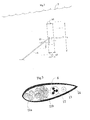
- figs 6a, 6b, 6c an example of an alternative never ending trajectory 7 of the vehicle 3 is shown in the same coordinate system as in fig 1 .
- the trajectory illustrated in figs 6a, 6b and 6c is formed as an oval.
- the illustrated never ending trajectory requires a swiveling device at the mooring 4 in order to avoid twisting the wire.
- the vehicle is provided with two additional turbines 18, 19, one at each end of the vehicle.
- the turbines are mounted to the vehicle by means of a bearing allowing the turbines to be free swiveling in a pitch direction.
- An electrical generator arranged to produce electrical energy is connected to each turbine.
- a cable connects each additional turbine generator to the electrical cable 12 of the wire 6 for further distribution.
- the vehicle is in the illustrated examples a wing.
- the invention is not limited to a vehicle in the form of a wing.
- the vehicle can be formed by two or more wings arranged on top of each other and separated by means of spacer elements.
Abstract
Description
- The present invention relates to a submersible plant for producing energy comprising at least one turbine.
- One of the main global problems to be solved is how to supply energy to the population of the world. The use of fossil fuels has to be decreased and substituted with renewable sources of energy.
- A significant percentage of the efforts to use renewable sources of energy have been concentrated on wind powered systems. The wind powered generating systems have a problem in that wind energy is inherently intermittent.
- There exist today submersible plants for producing electricity from ocean currents. Those plants are fastened in the sea bottom by means of wires and comprise turbines arranged to be driven by tidal water.
- However, the power generated from the submersible plants needs to be increased without substantially increasing the costs in order to be commercially attractive.
- One object to the invention is to increase the power output from submersible plants.
- This has been achieved by means of a submersible plant for producing energy comprising at least one turbine and characterized in that said turbine is mounted on a stream-driven vehicle and in that said stream-driven vehicle is secured in a structure by means of at least one wire. The structure can be stationary, such as a mooring at the bottom of a sea, river, lake etc or a wind power plant or stationary submersible plant located in a sea or lake. The structure can also be movable, such as a ship.
- The vehicle of the plant according to the present invention moves with a velocity which is many times (characteristically between 10-20 times) higher than the streaming velocity of the water. Thereby, the efficiency of the on board turbine arrangement is much higher than the efficiency of a stationary rotor arrangement.
- The plant is preferably mounted in environments with well-defined, predictable streams with regard to direction and velocity such as in rivers, in tide affected areas and in ocean streams.
- The plant in accordance of the invention enables environment friendly, rational and cost effective generation of energy, for example electrical energy, from relatively weak ocean currents and tide streams on cites close to the coast. The plant in accordance with the present invention can also be used offshore at relatively large depths, where few competing techniques are available.
- In accordance with one preferred embodiment of the present invention the stream driven vehicle is a wing, ie a lifting body.
- The vehicle is in accordance with another preferred embodiment substantially free swiveling at least in a pitch direction. The vehicle adapts to an optimum working point in the pitch direction. The vehicle is preferably also free swiveling in a roll direction in relation to the turbine. Thereby the turbine will face the relative stream direction, ie the water stream will be forced upon the turbine from a direction perpendicular to a plane defined by the turbine blades.
- In one preferred embodiment wherein the vehicle is free swiveling in accordance with the above, at least one of the turbines is mounted on the vehicle via a rod and a swivel coupling is mounted at one end of the rod for pivotally connecting either the turbine or the vehicle to the rod. The swivel coupling comprises for example a universal bearing.
- In another preferred embodiment wherein the vehicle is free swiveling in accordance with the above, at least one of the turbines is directly mounted on the vehicle by means of a swivel coupling.
- In yet another preferred embodiment of the invention the stream-driven vehicle is provided with steering means and a control unit is arranged to provide control signals to the steering means for steering the vehicle in a predetermined trajectory. The steering means can then include one or more control surfaces.
- Further, the wire will preferably be stretched and accordingly the predetermined trajectory is formed in a spherical surface. In order to provide the stream-driving, the predetermined trajectory will at least partly cross the stream-direction.
- In accordance with one embodiment of the invention, the turbine is operatively connected to a generator arranged to produce electrical energy. The generator can be operatively connected to an electrical cable arranged to distribute said electrical energy. The electrical cable is for example at least partly integrated in the wire. However, if an electrical cable connecting to the vehicle is not desirable, the produced electrical energy can for example be used for electrolyzing the water and production of hydrogen gas directly at the vehicle.
-
-
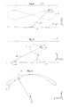
Fig. 1a shows an example of a submersible plant arrangement in accordance with a first example of the invention in a xy-plane, wherein x denotes a horizontal direction perpendicular to the stream direction and y denotes the vertical direction. -
Fig. 1b shows the submersible plant arrangement ofFig. 1a in a yz-plane, wherein z denotes a horizontal stream direction. -
Fig. 1c shows the submersible plant arrangement ofFig. 1a in a xz-plane. -
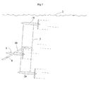
Fig. 2 shows a first example of a stream driven vehicle of the submersible plant offig 1 . -
Fig. 3 shows in cross-section an example of a wire of the submersible plant offig 1 . -
Fig 4 shows an example of a mounting of a turbine to the vehicle of the submersible plant offig 1 . -
Fig. 5 shows an example of a control unit of the submersible plant offig 1 . -
Fig. 6a shows an example of a submersible plant arrangement in accordance with a second example of the invention in a xy-plane, wherein x denotes a horizontal direction perpendicular to the stream direction and y denotes the vertical direction. -
Fig. 6b shows the submersible plant arrangement ofFig. 6a in a yz-plane, wherein z denotes a horizontal stream direction. -
Fig. 6c shows the submersible plant arrangement ofFig. 6a in a xz-plane. -
Fig. 7 shows a second example of a stream driven vehicle of the submersible plant offig 1 . - In
figs 1a, 1b and 1c , asubmersible plant 1 is arranged under thewater surface 2 of for example the sea. Theplant 1 comprises a stream-drivenvehicle 3 secured in amooring 4 at thebottom 5 of the sea by means of awire 6. The length of thewire 6 is for example 50-200 meters. Infig 1a , z defines the horizontal stream direction, x a horizontal direction perpendicular to the stream direction and y defines the vertical direction. The vehicle can move freely within a range of the wire. However, infigs 1a, 1b and 1c , the vehicle follows a never-endingtrajectory 7 formed as the digit eight in a spherical surface with a bending radius equal to the length of the wire. The trajectory is preferably chosen such that the vehicle is always is beneath the sea surface. For example, the trajectory can be chosen such that the wire always ends 10-20 meters beneath the sea surface. Thereby the vehicle is not subjected to the turbulences usually present close to the surface and the risk of turbine cavitation can be minimized. The advantage of having a trajectory formed as the digit eight is that then the wire will not be twisted and accordingly, there is no need for connecting thewire 6 to themooring 4 by means of a swiveling device - In
fig 2 the stream-drivenvehicle 3 is a wing, ie a lifting body. The wing has for example a wing span s of about 15 meters and a width (cord) c which is for example 2-3 meters. The thickness of the wing may be 10-20% of the width. The wing is preferably formed by a spar supporting a surface structure. The spar is in one example made of a carbon fibre composite material. The surface structure is for example made of a glass fibre composite material. - A
turbine arrangement 9, in the illustrated embodiment comprising one turbine, is mounted to the vehicle structure by means of arod 10. Theturbine 9 androd 10 can be made of a metal or compound of metals, for example stainless steal. The diameter of the turbine is for example 1 to 1.5 meters. Thewire 6 is secured in theturbine 9. Theturbine 9 is operatively connected to a generator (not shown) arranged to produce electrical energy distributed via an electrical cable integrated within or secured to the wire. The electricity is distributed further from themooring 4 via a distribution network. - The density of the
vehicle 3 with itsturbine 9,rod 10 andwire 6 is preferably somewhat lower than the density of water. - In
fig 3 thewire 6 comprises two supportingtwisted cables electrical cable 12. The wire further comprises an additional electrical low voltage oroptical cable 13 for data communication with thevehicle 3. The supportingcables electrical cable 12 and low voltage oroptical cable 13 are enclosed in acover 14, for example made of a rubber material or plastic. - The
vehicle 3 is preferably powered only by the stream. However, in certain situations, for example when an error condition has appeared, the electrical generator can be used as an electrical engine powered by one or several batteries (not shown) mounted at the vehicle. Then, the generator/engine can drive the vehicle to the sea surface for transportation to a service site. This of course presumes that the vehicle first has been released from the wire. The generator can be used as an engine also for other purposes, for example for driving the vehicle to a parking location at the sea bottom. - In
fig 4 , therod 10 is mounted to thevehicle 3 by means of abearing arrangement 8 so that the vehicle is free swiveling at least in pitch direction but preferably also in roll direction. Preferably, the relationship between the turbine and the vehicle is fixed in yaw direction. The fact that the vehicle is free swiveling in relation to the turbine secures that the turbine arrangement always substantially faces the relative stream direction, ie the stream direction is perpendicular to a plane defined by the turbine blades. Infig 4 , the bearing arrangement is a universal bearing. The universal bearing provides for the free swiveling feature in pitch and roll direction. In the example illustrated infig 4 , the turbine is fixedly mounted to the rod, or integrated therewith while the other end of the rod facing the vehicle is mounted to the vehicle by means of thebearing arrangement 8. However, in an alternative example (not shown) thebearing arrangement 8 is mounted at the end of the rod facing the turbine. - In
fig 5 , acontrol system 15 mounted on the vehicle is arranged to guide the vehicle in thepredetermined trajectory 7 without exceeding the structural load limitations on the vehicle and turbine and electrical load limitations on the turbine. Other functional requirements of thecontrol system 15 are to stabilize thevehicle 3 and optimize the power output of the device in the never-endingtrajectory 7. - The
control system 15 has in the shown example four input signals for guidance and tracking. The first input signal, namely current tilt angle α (seefig 1b ), and the second input signal, namely current rotational angle β (seefig 1c ), are provided from angle detecting devices (not shown) mounted at themooring 4 of thewire 6 and fed for example via the previously describedelectrical cable 13 in thewire 6 to thecontrol system 15. The first, tilt angle signal α defines the angle between thewire 6 and the horizontal plane. The second, rotational angle signal β defines the angle between thewire 6 and the horizontal stream direction. Two angle measuring arrangements are further mounted in thevehicle bearing arrangement 8. These two angle measuring devices are arranged to provide a third input signal to the control system indicating a roll angle between thevehicle 3 androd 10 and to provide a fourth input signal indicating a pitch angle between thevehicle 3 and therod 10. Further sensor data can for example be provided from an inertial navigation system at the vehicle for refining the computations of thecontrol system 14. - The tilt angle data α, rotational angle data β, roll angle data and pitch angle data are processed by the control system and a command angle is outputted for a first control surface 16 (
fig 2 ) of thevehicle 3 and a command angle for thesecond control surface 17 of thevehicle 3. In processing, values are calculated for pitch and yaw movements required by the vehicle in order to follow the predetermined trajectory. The control system then provides in a second step a command angle for each servo actuator (not shown) mounted on its correspondingcontrol surface second surfaces wire 6 can be approximated as a linear rod. - In
figs 6a, 6b, 6c , an example of an alternative never endingtrajectory 7 of thevehicle 3 is shown in the same coordinate system as infig 1 . The trajectory illustrated infigs 6a, 6b and 6c is formed as an oval. The illustrated never ending trajectory requires a swiveling device at themooring 4 in order to avoid twisting the wire. - In
fig 7 the vehicle is provided with twoadditional turbines electrical cable 12 of thewire 6 for further distribution. - The vehicle is in the illustrated examples a wing. However, the invention is not limited to a vehicle in the form of a wing. For example, the vehicle can be formed by two or more wings arranged on top of each other and separated by means of spacer elements.
Claims (17)
- A submersible plant (1) for producing electrical energy from a water stream,
said plant (1) comprising at least one turbine arrangement (9, 18, 19) secured in a structure (4) by means of a wire (6),
characterized inthat the turbine arrangement (9, 18, 19) is mounted to a stream-driven vehicle (3) that is formed by at least one wing and that can move freely within a range of the wire (6),said vehicle (3) being provided with steering means (16, 17) and a control unit (15), wherein the control unit (15) is arranged to provide control signals to the steering means (16, 17) for steering the vehicle (3) in a trajectory (7) at least partly crossing the direction of the water stream,wherein said vehicle (3) is capable of, when steered in said trajectory (7), being driven by the water stream with a velocity which is many times higher than the streaming velocity of the water. - A submersible plant (1) according to claim 1,
characterized in
that it comprises means for providing input signals to the control unit (15) regarding a current tilt angle α, i.e. the angle defined between the wire (6) and a horizontal plane, and a current rotational angle β, i.e. the angle defined between the wire (6) and the horizontal stream direction. - A submersible plant (1) according to claim 1 or 2,
characterized in
that the trajectory (7) is a never ending trajectory. - A submersible plant (1) according to claim 3,
characterized in
that the trajectory (7) is formed as the digit 8. - A submersible plant (1) according to any of the above claims,
characterized in
that the trajectory (7) is formed in a spherical surface that has a bending radius substantially equal to the length of the wire (6). - A submersible plant (1) according to any of the above claims,
characterized in
that a major part of the trajectory (7) is directed substantially perpendicular to the direction of the water stream such that a varying rotational angle β is obtained between the wire (6) and the horizontal direction of the water stream when the vehicle (3) operates in its trajectory (7). - A submersible plant (1) according to any of the above claims,
characterized in
that the at least one turbine arrangement (9, 18, 19) comprises a turbine operatively connected to a generator arranged to produce electrical energy. - A submersible plant (1) according to any of the above claims,
characterized in that said steering means (16, 17) includes at least one control surface. - A submersible plant (1) according to claim 7, characterized in that the generator is operatively connected to an electrical cable (12) arranged to distribute said electrical energy.
- A submersible plant (1) according to claim 9, characterized in that said electrical cable (12) is at least partly integrated in the wire (6).
- Method for operating a submersible plant (1) according to claim 1,
characterized in
that the method comprises the step of:- steering the vehicle (3) in a trajectory (7) at least partly crossing the direction of the water stream such as to allow the vehicle (3) to be driven by the water stream with a velocity which is many times higher than the streaming velocity of the water. - Method according to claim 11,
characterized in
that it further comprises the step of:- providing control signals to the steering means (16, 17) of the vehicle (3) using the control unit (15). - Method according to claim 11 or 12,
characterized in
that it further comprises the step of:- providing input signals to the control unit (15) regarding a current tilt angle α, i.e. the angle defined between the wire (6) and a horizontal plane, and a current rotational angle β, i.e. the angle defined between the wire (6) and the horizontal stream direction. - Method according to any of claims 11-13,
characterized in
that the trajectory (7) is a never ending trajectory. - Method according to claim 14,
characterized in
that the trajectory (7) is formed as the digit 8. - Method according to any of claims 11-15,
characterized in
that the trajectory (7) is formed in a spherical surface that has a bending radius substantially equal to the length of the wire (6). - Method according to any of claims 11-16,
characterized in
that it comprises the step of:- steering the vehicle (3) in a direction substantially perpendicular to the direction of the water stream such that a varying rotational angle β is obtained between the wire (6) and the horizontal stream direction during operation.
Priority Applications (2)
| Application Number | Priority Date | Filing Date | Title |
|---|---|---|---|
| ES10183891.0T ES2610129T3 (en) | 2006-02-02 | 2006-02-02 | A submersible plant |
| EP10183891.0A EP2295792B1 (en) | 2006-02-02 | 2006-02-02 | A submersible plant |
Applications Claiming Priority (2)
| Application Number | Priority Date | Filing Date | Title |
|---|---|---|---|
| EP06101208A EP1816345A1 (en) | 2006-02-02 | 2006-02-02 | Tidal energy system |
| EP10183891.0A EP2295792B1 (en) | 2006-02-02 | 2006-02-02 | A submersible plant |
Related Parent Applications (4)
| Application Number | Title | Priority Date | Filing Date |
|---|---|---|---|
| EP06101208A Division EP1816345A1 (en) | 2006-02-02 | 2006-02-02 | Tidal energy system |
| EP06101208A Previously-Filed-Application EP1816345A1 (en) | 2006-02-02 | 2006-02-02 | Tidal energy system |
| EP06101208 Previously-Filed-Application | 2006-02-02 | ||
| EP06101208.4 Division | 2006-02-02 |
Publications (3)
| Publication Number | Publication Date |
|---|---|
| EP2295792A2 true EP2295792A2 (en) | 2011-03-16 |
| EP2295792A3 EP2295792A3 (en) | 2011-12-21 |
| EP2295792B1 EP2295792B1 (en) | 2016-11-02 |
Family
ID=36754214
Family Applications (2)
| Application Number | Title | Priority Date | Filing Date |
|---|---|---|---|
| EP10183891.0A Active EP2295792B1 (en) | 2006-02-02 | 2006-02-02 | A submersible plant |
| EP06101208A Withdrawn EP1816345A1 (en) | 2006-02-02 | 2006-02-02 | Tidal energy system |
Family Applications After (1)
| Application Number | Title | Priority Date | Filing Date |
|---|---|---|---|
| EP06101208A Withdrawn EP1816345A1 (en) | 2006-02-02 | 2006-02-02 | Tidal energy system |
Country Status (12)
| Country | Link |
|---|---|
| US (1) | US8246293B2 (en) |
| EP (2) | EP2295792B1 (en) |
| JP (1) | JP5102779B2 (en) |
| KR (1) | KR101383306B1 (en) |
| CN (2) | CN102506008A (en) |
| AU (1) | AU2007222491B2 (en) |
| CA (1) | CA2637270C (en) |
| EC (1) | ECSP088649A (en) |
| ES (1) | ES2610129T3 (en) |
| MX (1) | MX2008009564A (en) |
| NZ (1) | NZ569753A (en) |
| WO (1) | WO2007101756A1 (en) |
Cited By (1)
| Publication number | Priority date | Publication date | Assignee | Title |
|---|---|---|---|---|
| EP2781733A2 (en) | 2013-03-19 | 2014-09-24 | Aktiebolaget SKF | Submerged system for anchoring a marine device |
Families Citing this family (43)
| Publication number | Priority date | Publication date | Assignee | Title |
|---|---|---|---|---|
| JPH0757904A (en) * | 1993-08-13 | 1995-03-03 | Kobe Steel Ltd | Diamond semiconductor device |
| US8388684B2 (en) | 2002-05-23 | 2013-03-05 | Pioneer Signal Technology, Inc. | Artificial disc device |
| GB0604061D0 (en) * | 2006-03-01 | 2006-04-12 | Invibio Ltd | Polymetric materials |
| WO2008034135A2 (en) * | 2006-09-15 | 2008-03-20 | Pioneer Surgical Technology, Inc. | Joint arthroplasty devices having articulating members |
| US8715350B2 (en) | 2006-09-15 | 2014-05-06 | Pioneer Surgical Technology, Inc. | Systems and methods for securing an implant in intervertebral space |
| GB0621228D0 (en) * | 2006-10-25 | 2006-12-06 | Invibio Ltd | Polymeric material |
| GB0621227D0 (en) * | 2006-10-25 | 2006-12-06 | Invibio Ltd | Polymeric material |
| US8764391B2 (en) | 2009-09-10 | 2014-07-01 | Osirius International | Hydrokinetic turbine structure and system |
| US20110095530A1 (en) * | 2009-10-26 | 2011-04-28 | Honeywell International Inc. | Tethered aquatic device with water power turbine |
| DE102010025070A1 (en) * | 2010-06-25 | 2011-12-29 | Smart Utilities Solutions Gmbh | Hydraulic power device i.e. hydropower turbine for generating water in e.g. stationary hydroelectric power plant, has ventilation device designed such that gas is exhausted from chamber, and water is sent into chamber by suppression of gas |
| WO2012040834A1 (en) * | 2010-10-01 | 2012-04-05 | UNIVERSITé LAVAL | Oscillating hydrofoil, turbine, propulsive system and method for transmitting energy |
| DE102011003483A1 (en) | 2011-02-02 | 2012-08-02 | Robert Bosch Gmbh | Method and device for converting energy |
| US9198769B2 (en) | 2011-12-23 | 2015-12-01 | Pioneer Surgical Technology, Inc. | Bone anchor assembly, bone plate system, and method |
| EP2610481B1 (en) * | 2011-12-27 | 2017-01-25 | Minesto AB | Tether for submerged moving vehicle |
| WO2013162520A2 (en) * | 2012-04-24 | 2013-10-31 | Anadarko Petroleum Corporation | Subsystems for a water current power generation system |
| US10036365B2 (en) | 2012-05-10 | 2018-07-31 | The Boeing Company | System and method for converting fluid motion into electrical power |
| AU2012384575A1 (en) | 2012-07-05 | 2015-02-05 | Minesto Ab | Arrangement for a self-lubricating bearing |
| KR102046207B1 (en) * | 2012-12-13 | 2019-11-18 | 미네스토 에이비 | Method and system for controlling a flying wing |
| MX341057B (en) * | 2013-02-04 | 2016-08-05 | Minesto Ab | Power plant comprising a structure and a vehicle. |
| JP6150046B2 (en) * | 2013-04-22 | 2017-06-21 | 株式会社Ihi | Ocean current power generator |
| MX2015016218A (en) * | 2013-05-30 | 2016-03-01 | Minesto Ab | Submersible power plant having multiple turbines. |
| CA2917982A1 (en) | 2013-07-12 | 2015-01-15 | Minesto Ab | Wing and turbine configuration for power plant |
| US9126675B2 (en) * | 2013-09-16 | 2015-09-08 | Google Inc. | Methods and systems for transitioning an aerial vehicle between crosswind flight and hover flight |
| US9126682B2 (en) * | 2013-09-16 | 2015-09-08 | Google Inc. | Methods and systems for transitioning an aerial vehicle between hover flight and crosswind flight |
| US9174732B2 (en) * | 2013-12-30 | 2015-11-03 | Google Inc. | Methods and systems for transitioning an aerial vehicle between crosswind flight and hover flight |
| EP3102820B1 (en) * | 2014-02-07 | 2018-10-17 | Minesto AB | Submersible power plant |
| JP6173236B2 (en) * | 2014-02-21 | 2017-08-02 | 伊佐男 安田 | Ocean current power generation system |
| EP3186501B1 (en) * | 2014-08-29 | 2019-02-06 | Minesto AB | Method for controlling the operation a submersible power plant |
| CA2983451C (en) * | 2015-05-01 | 2020-10-06 | Big Moon Power, Inc. | Systems and methods for tidal energy conversion and electrical power generation |
| CN105298729A (en) * | 2015-11-18 | 2016-02-03 | 华中科技大学 | Underwater kite and method for achieving tidal power generation and ocean current power generation by means of underwater kite |
| US20190063398A1 (en) * | 2016-04-06 | 2019-02-28 | Minesto Ab | Submersible plant comprising buoyant tether |
| US10807680B2 (en) * | 2016-10-21 | 2020-10-20 | National Tsing Hua University | Mooring system and method for power generation systems and other payloads in water flows |
| US9745951B1 (en) * | 2016-11-07 | 2017-08-29 | Robert E. Doyle | Self-positioning robotic subsea power generation system |
| US10458385B2 (en) | 2017-04-28 | 2019-10-29 | Big Moon Power, Inc. | Systems and methods for tidal energy conversion and electrical power generation using a rotatable drag panel |
| JP6483186B2 (en) * | 2017-05-08 | 2019-03-13 | 伊佐男 安田 | Ocean current power generation system and mooring lines suitable for use in the system |
| CA3074834A1 (en) | 2017-09-08 | 2019-03-14 | Pioneer Surgical Technology, Inc. | Intervertebral implants, instruments, and methods |
| USD907771S1 (en) | 2017-10-09 | 2021-01-12 | Pioneer Surgical Technology, Inc. | Intervertebral implant |
| CN107893732A (en) * | 2017-11-20 | 2018-04-10 | 哈尔滨工业大学 | A kind of removable float type marine energy TRT |
| CN108661850B (en) * | 2018-04-13 | 2020-03-24 | 中国航天空气动力技术研究院 | Motion trail control method for rope type ocean current generator |
| CN108915928B (en) * | 2018-07-10 | 2020-07-17 | 浙江中超新材料股份有限公司 | Water turbine type power generation environment observation platform |
| WO2020130897A1 (en) * | 2018-12-20 | 2020-06-25 | Minesto Ab | Submersible power plant for producing electrical power |
| CN113431727A (en) * | 2020-12-31 | 2021-09-24 | 潍坊新力蒙水产技术有限公司 | Horizontal sinking split type axial flow power generation device |
| US11933261B2 (en) * | 2021-02-16 | 2024-03-19 | Aqua Satellite, Inc. | Methods for harnessing wave energy |
Citations (5)
| Publication number | Priority date | Publication date | Assignee | Title |
|---|---|---|---|---|
| DE2902518A1 (en) * | 1978-01-25 | 1979-07-26 | Philippe Vauthier | ELECTRIC HYDRO GENERATOR |
| GB2317422A (en) * | 1995-11-29 | 1998-03-25 | Kenneth William Upton | Kite energy turbine device |
| US6168373B1 (en) * | 1999-04-07 | 2001-01-02 | Philippe Vauthier | Dual hydroturbine unit |
| US20020040948A1 (en) * | 2000-08-30 | 2002-04-11 | Ragner Gary Dean | Axial-mode linear wind-trubine |
| GB2410299A (en) * | 2004-01-22 | 2005-07-27 | Thomas Tsoi Hei Ma | An ocean power converter |
Family Cites Families (14)
| Publication number | Priority date | Publication date | Assignee | Title |
|---|---|---|---|---|
| US4383182A (en) * | 1975-06-11 | 1983-05-10 | Bowley Wallace W | Underwater power generator |
| JPS521346A (en) * | 1975-06-24 | 1977-01-07 | U M I:Kk | Power generating process availing ocean current and its device |
| JPS54126386A (en) * | 1978-03-24 | 1979-10-01 | Motohisa Hirose | Tilt mooring system underwater power generating ship |
| US4737070A (en) * | 1985-07-31 | 1988-04-12 | Yamaha Hatsudoki Kabushiki Kaisha | Water powered device |
| GB9111013D0 (en) * | 1991-05-22 | 1991-07-17 | I T Power Limited | Floating water current turbine system |
| US5440176A (en) * | 1994-10-18 | 1995-08-08 | Haining Michael L | Ocean current power generator |
| US6091161A (en) * | 1998-11-03 | 2000-07-18 | Dehlsen Associates, L.L.C. | Method of controlling operating depth of an electricity-generating device having a tethered water current-driven turbine |
| US6531788B2 (en) | 2001-02-22 | 2003-03-11 | John H. Robson | Submersible electrical power generating plant |
| US6856036B2 (en) * | 2001-06-26 | 2005-02-15 | Sidney Irving Belinsky | Installation for harvesting ocean currents (IHOC) |
| AU2002318086B2 (en) * | 2001-07-11 | 2007-09-13 | Hydra Tidal Energy Technology As | Plant, generator and propeller element for generating energy from watercurrents |
| GB0123802D0 (en) * | 2001-10-04 | 2001-11-21 | Rotech Holdings Ltd | Power generator and turbine unit |
| US6982498B2 (en) * | 2003-03-28 | 2006-01-03 | Tharp John E | Hydro-electric farms |
| US20090226296A1 (en) * | 2007-09-12 | 2009-09-10 | Bibeau Eric L | Efficiency enhancement and protection method for ocean, river and channel kinetic hydro turbines |
| US8981582B2 (en) * | 2009-07-17 | 2015-03-17 | Kurt Paul Grossman | Submerged power generator |
-
2006
- 2006-02-02 ES ES10183891.0T patent/ES2610129T3/en active Active
- 2006-02-02 EP EP10183891.0A patent/EP2295792B1/en active Active
- 2006-02-02 EP EP06101208A patent/EP1816345A1/en not_active Withdrawn
-
2007
- 2007-01-31 AU AU2007222491A patent/AU2007222491B2/en active Active
- 2007-01-31 JP JP2008552798A patent/JP5102779B2/en active Active
- 2007-01-31 WO PCT/EP2007/050924 patent/WO2007101756A1/en active Application Filing
- 2007-01-31 KR KR1020087019073A patent/KR101383306B1/en active IP Right Grant
- 2007-01-31 US US12/162,980 patent/US8246293B2/en active Active
- 2007-01-31 CN CN2011103521172A patent/CN102506008A/en active Pending
- 2007-01-31 CN CN2007800042924A patent/CN101379291B/en active Active
- 2007-01-31 NZ NZ569753A patent/NZ569753A/en unknown
- 2007-01-31 MX MX2008009564A patent/MX2008009564A/en active IP Right Grant
- 2007-01-31 CA CA2637270A patent/CA2637270C/en active Active
-
2008
- 2008-07-28 EC EC2008008649A patent/ECSP088649A/en unknown
Patent Citations (5)
| Publication number | Priority date | Publication date | Assignee | Title |
|---|---|---|---|---|
| DE2902518A1 (en) * | 1978-01-25 | 1979-07-26 | Philippe Vauthier | ELECTRIC HYDRO GENERATOR |
| GB2317422A (en) * | 1995-11-29 | 1998-03-25 | Kenneth William Upton | Kite energy turbine device |
| US6168373B1 (en) * | 1999-04-07 | 2001-01-02 | Philippe Vauthier | Dual hydroturbine unit |
| US20020040948A1 (en) * | 2000-08-30 | 2002-04-11 | Ragner Gary Dean | Axial-mode linear wind-trubine |
| GB2410299A (en) * | 2004-01-22 | 2005-07-27 | Thomas Tsoi Hei Ma | An ocean power converter |
Cited By (1)
| Publication number | Priority date | Publication date | Assignee | Title |
|---|---|---|---|---|
| EP2781733A2 (en) | 2013-03-19 | 2014-09-24 | Aktiebolaget SKF | Submerged system for anchoring a marine device |
Also Published As
| Publication number | Publication date |
|---|---|
| CN102506008A (en) | 2012-06-20 |
| AU2007222491B2 (en) | 2012-03-08 |
| CA2637270A1 (en) | 2007-09-13 |
| WO2007101756A1 (en) | 2007-09-13 |
| ES2610129T3 (en) | 2017-04-26 |
| US8246293B2 (en) | 2012-08-21 |
| ECSP088649A (en) | 2008-09-29 |
| CA2637270C (en) | 2014-12-23 |
| MX2008009564A (en) | 2008-09-24 |
| EP1816345A1 (en) | 2007-08-08 |
| EP2295792B1 (en) | 2016-11-02 |
| NZ569753A (en) | 2011-04-29 |
| US20090185904A1 (en) | 2009-07-23 |
| JP5102779B2 (en) | 2012-12-19 |
| KR101383306B1 (en) | 2014-04-09 |
| JP2009525427A (en) | 2009-07-09 |
| KR20080099258A (en) | 2008-11-12 |
| AU2007222491A1 (en) | 2007-09-13 |
| CN101379291B (en) | 2013-07-31 |
| CN101379291A (en) | 2009-03-04 |
| EP2295792A3 (en) | 2011-12-21 |
Similar Documents
| Publication | Publication Date | Title |
|---|---|---|
| EP2295792B1 (en) | A submersible plant | |
| US7441988B2 (en) | Submerged power generating apparatus | |
| CA3000861C (en) | Translating foil system for harvesting kinetic energy from wind and flowing water | |
| CN102637039B (en) | Ocean towed line array three-wing positioning method | |
| US9784236B2 (en) | Flexible water turbine | |
| CN111094739B (en) | Wave power energy generator | |
| US20110266805A1 (en) | Submersible plant | |
| GB2468853A (en) | Helical axial flow water turbine | |
| CN102086833A (en) | Dam-free electricity generation method of tension-type structured water wheel | |
| CN112761882A (en) | Floating platform for generating electricity by combining wind energy and ocean current energy | |
| CN214660625U (en) | Floating platform for generating electricity by combining wind energy and ocean current energy | |
| EP4012883A1 (en) | Floating vessel and method for controlling thereof | |
| KR102427102B1 (en) | A tidal power generator and tidal power generation system in deep water | |
| KR102192399B1 (en) | Mooring system of float generator | |
| JP2016217151A (en) | Power generation system and control method of power generation system | |
| JP2022117496A (en) | Offshore wind power generation system | |
| CN115013222A (en) | Ocean current power generation device and self-powered submerged buoy system | |
| KR20140147794A (en) | Small hydraulic power apparatus | |
| WO2023230087A1 (en) | Marine current turbine platform with faired spar | |
| SK8989Y1 (en) | Deep water wind turbine | |
| JP2012071809A (en) | Method for moving and stopping object in arbitrary direction by using force of flow |
Legal Events
| Date | Code | Title | Description |
|---|---|---|---|
| PUAI | Public reference made under article 153(3) epc to a published international application that has entered the european phase |
Free format text: ORIGINAL CODE: 0009012 |
|
| AC | Divisional application: reference to earlier application |
Ref document number: 1816345 Country of ref document: EP Kind code of ref document: P |
|
| AK | Designated contracting states |
Kind code of ref document: A2 Designated state(s): AT BE BG CH CY CZ DE DK EE ES FI FR GB GR HU IE IS IT LI LT LU LV MC NL PL PT RO SE SI SK TR |
|
| PUAL | Search report despatched |
Free format text: ORIGINAL CODE: 0009013 |
|
| AK | Designated contracting states |
Kind code of ref document: A3 Designated state(s): AT BE BG CH CY CZ DE DK EE ES FI FR GB GR HU IE IS IT LI LT LU LV MC NL PL PT RO SE SI SK TR |
|
| RIC1 | Information provided on ipc code assigned before grant |
Ipc: F03B 17/00 20060101ALI20111116BHEP Ipc: F03D 5/00 20060101ALI20111116BHEP Ipc: F03B 17/06 20060101AFI20111116BHEP |
|
| 17P | Request for examination filed |
Effective date: 20120420 |
|
| RIC1 | Information provided on ipc code assigned before grant |
Ipc: F03B 17/00 20060101ALI20160224BHEP Ipc: F03D 5/00 20060101ALI20160224BHEP Ipc: F03B 17/06 20060101AFI20160224BHEP |
|
| GRAP | Despatch of communication of intention to grant a patent |
Free format text: ORIGINAL CODE: EPIDOSNIGR1 |
|
| INTG | Intention to grant announced |
Effective date: 20160502 |
|
| GRAS | Grant fee paid |
Free format text: ORIGINAL CODE: EPIDOSNIGR3 |
|
| RAP1 | Party data changed (applicant data changed or rights of an application transferred) |
Owner name: MINESTO AB |
|
| GRAA | (expected) grant |
Free format text: ORIGINAL CODE: 0009210 |
|
| AC | Divisional application: reference to earlier application |
Ref document number: 1816345 Country of ref document: EP Kind code of ref document: P |
|
| AK | Designated contracting states |
Kind code of ref document: B1 Designated state(s): AT BE BG CH CY CZ DE DK EE ES FI FR GB GR HU IE IS IT LI LT LU LV MC NL PL PT RO SE SI SK TR |
|
| REG | Reference to a national code |
Ref country code: GB Ref legal event code: FG4D |
|
| REG | Reference to a national code |
Ref country code: AT Ref legal event code: REF Ref document number: 842116 Country of ref document: AT Kind code of ref document: T Effective date: 20161115 Ref country code: CH Ref legal event code: EP |
|
| REG | Reference to a national code |
Ref country code: IE Ref legal event code: FG4D |
|
| REG | Reference to a national code |
Ref country code: FR Ref legal event code: PLFP Year of fee payment: 12 |
|
| REG | Reference to a national code |
Ref country code: DE Ref legal event code: R096 Ref document number: 602006050808 Country of ref document: DE |
|
| REG | Reference to a national code |
Ref country code: NL Ref legal event code: FP |
|
| PG25 | Lapsed in a contracting state [announced via postgrant information from national office to epo] |
Ref country code: LV Free format text: LAPSE BECAUSE OF FAILURE TO SUBMIT A TRANSLATION OF THE DESCRIPTION OR TO PAY THE FEE WITHIN THE PRESCRIBED TIME-LIMIT Effective date: 20161102 |
|
| REG | Reference to a national code |
Ref country code: LT Ref legal event code: MG4D |
|
| REG | Reference to a national code |
Ref country code: AT Ref legal event code: MK05 Ref document number: 842116 Country of ref document: AT Kind code of ref document: T Effective date: 20161102 |
|
| REG | Reference to a national code |
Ref country code: ES Ref legal event code: FG2A Ref document number: 2610129 Country of ref document: ES Kind code of ref document: T3 Effective date: 20170426 |
|
| PG25 | Lapsed in a contracting state [announced via postgrant information from national office to epo] |
Ref country code: LT Free format text: LAPSE BECAUSE OF FAILURE TO SUBMIT A TRANSLATION OF THE DESCRIPTION OR TO PAY THE FEE WITHIN THE PRESCRIBED TIME-LIMIT Effective date: 20161102 Ref country code: GR Free format text: LAPSE BECAUSE OF FAILURE TO SUBMIT A TRANSLATION OF THE DESCRIPTION OR TO PAY THE FEE WITHIN THE PRESCRIBED TIME-LIMIT Effective date: 20170203 Ref country code: SE Free format text: LAPSE BECAUSE OF FAILURE TO SUBMIT A TRANSLATION OF THE DESCRIPTION OR TO PAY THE FEE WITHIN THE PRESCRIBED TIME-LIMIT Effective date: 20161102 |
|
| PG25 | Lapsed in a contracting state [announced via postgrant information from national office to epo] |
Ref country code: PL Free format text: LAPSE BECAUSE OF FAILURE TO SUBMIT A TRANSLATION OF THE DESCRIPTION OR TO PAY THE FEE WITHIN THE PRESCRIBED TIME-LIMIT Effective date: 20161102 Ref country code: BE Free format text: LAPSE BECAUSE OF NON-PAYMENT OF DUE FEES Effective date: 20170228 Ref country code: IS Free format text: LAPSE BECAUSE OF FAILURE TO SUBMIT A TRANSLATION OF THE DESCRIPTION OR TO PAY THE FEE WITHIN THE PRESCRIBED TIME-LIMIT Effective date: 20170302 Ref country code: PT Free format text: LAPSE BECAUSE OF FAILURE TO SUBMIT A TRANSLATION OF THE DESCRIPTION OR TO PAY THE FEE WITHIN THE PRESCRIBED TIME-LIMIT Effective date: 20170302 Ref country code: AT Free format text: LAPSE BECAUSE OF FAILURE TO SUBMIT A TRANSLATION OF THE DESCRIPTION OR TO PAY THE FEE WITHIN THE PRESCRIBED TIME-LIMIT Effective date: 20161102 Ref country code: FI Free format text: LAPSE BECAUSE OF FAILURE TO SUBMIT A TRANSLATION OF THE DESCRIPTION OR TO PAY THE FEE WITHIN THE PRESCRIBED TIME-LIMIT Effective date: 20161102 |
|
| PG25 | Lapsed in a contracting state [announced via postgrant information from national office to epo] |
Ref country code: SK Free format text: LAPSE BECAUSE OF FAILURE TO SUBMIT A TRANSLATION OF THE DESCRIPTION OR TO PAY THE FEE WITHIN THE PRESCRIBED TIME-LIMIT Effective date: 20161102 Ref country code: CZ Free format text: LAPSE BECAUSE OF FAILURE TO SUBMIT A TRANSLATION OF THE DESCRIPTION OR TO PAY THE FEE WITHIN THE PRESCRIBED TIME-LIMIT Effective date: 20161102 Ref country code: EE Free format text: LAPSE BECAUSE OF FAILURE TO SUBMIT A TRANSLATION OF THE DESCRIPTION OR TO PAY THE FEE WITHIN THE PRESCRIBED TIME-LIMIT Effective date: 20161102 Ref country code: DK Free format text: LAPSE BECAUSE OF FAILURE TO SUBMIT A TRANSLATION OF THE DESCRIPTION OR TO PAY THE FEE WITHIN THE PRESCRIBED TIME-LIMIT Effective date: 20161102 Ref country code: RO Free format text: LAPSE BECAUSE OF FAILURE TO SUBMIT A TRANSLATION OF THE DESCRIPTION OR TO PAY THE FEE WITHIN THE PRESCRIBED TIME-LIMIT Effective date: 20161102 |
|
| REG | Reference to a national code |
Ref country code: DE Ref legal event code: R097 Ref document number: 602006050808 Country of ref document: DE |
|
| PG25 | Lapsed in a contracting state [announced via postgrant information from national office to epo] |
Ref country code: BG Free format text: LAPSE BECAUSE OF FAILURE TO SUBMIT A TRANSLATION OF THE DESCRIPTION OR TO PAY THE FEE WITHIN THE PRESCRIBED TIME-LIMIT Effective date: 20170202 Ref country code: BE Free format text: LAPSE BECAUSE OF FAILURE TO SUBMIT A TRANSLATION OF THE DESCRIPTION OR TO PAY THE FEE WITHIN THE PRESCRIBED TIME-LIMIT Effective date: 20161102 Ref country code: IT Free format text: LAPSE BECAUSE OF FAILURE TO SUBMIT A TRANSLATION OF THE DESCRIPTION OR TO PAY THE FEE WITHIN THE PRESCRIBED TIME-LIMIT Effective date: 20161102 |
|
| PLBE | No opposition filed within time limit |
Free format text: ORIGINAL CODE: 0009261 |
|
| STAA | Information on the status of an ep patent application or granted ep patent |
Free format text: STATUS: NO OPPOSITION FILED WITHIN TIME LIMIT |
|
| PG25 | Lapsed in a contracting state [announced via postgrant information from national office to epo] |
Ref country code: MC Free format text: LAPSE BECAUSE OF FAILURE TO SUBMIT A TRANSLATION OF THE DESCRIPTION OR TO PAY THE FEE WITHIN THE PRESCRIBED TIME-LIMIT Effective date: 20161102 |
|
| REG | Reference to a national code |
Ref country code: CH Ref legal event code: PL |
|
| 26N | No opposition filed |
Effective date: 20170803 |
|
| PG25 | Lapsed in a contracting state [announced via postgrant information from national office to epo] |
Ref country code: CH Free format text: LAPSE BECAUSE OF NON-PAYMENT OF DUE FEES Effective date: 20170228 Ref country code: LI Free format text: LAPSE BECAUSE OF NON-PAYMENT OF DUE FEES Effective date: 20170228 |
|
| PG25 | Lapsed in a contracting state [announced via postgrant information from national office to epo] |
Ref country code: SI Free format text: LAPSE BECAUSE OF FAILURE TO SUBMIT A TRANSLATION OF THE DESCRIPTION OR TO PAY THE FEE WITHIN THE PRESCRIBED TIME-LIMIT Effective date: 20161102 |
|
| PG25 | Lapsed in a contracting state [announced via postgrant information from national office to epo] |
Ref country code: LU Free format text: LAPSE BECAUSE OF NON-PAYMENT OF DUE FEES Effective date: 20170202 |
|
| REG | Reference to a national code |
Ref country code: FR Ref legal event code: PLFP Year of fee payment: 13 |
|
| PG25 | Lapsed in a contracting state [announced via postgrant information from national office to epo] |
Ref country code: HU Free format text: LAPSE BECAUSE OF FAILURE TO SUBMIT A TRANSLATION OF THE DESCRIPTION OR TO PAY THE FEE WITHIN THE PRESCRIBED TIME-LIMIT; INVALID AB INITIO Effective date: 20060202 |
|
| PG25 | Lapsed in a contracting state [announced via postgrant information from national office to epo] |
Ref country code: CY Free format text: LAPSE BECAUSE OF NON-PAYMENT OF DUE FEES Effective date: 20161102 |
|
| REG | Reference to a national code |
Ref country code: DE Ref legal event code: R082 Ref document number: 602006050808 Country of ref document: DE Representative=s name: 2K PATENT- UND RECHTSANWAELTE PARTNERSCHAFT MB, DE |
|
| PG25 | Lapsed in a contracting state [announced via postgrant information from national office to epo] |
Ref country code: TR Free format text: LAPSE BECAUSE OF FAILURE TO SUBMIT A TRANSLATION OF THE DESCRIPTION OR TO PAY THE FEE WITHIN THE PRESCRIBED TIME-LIMIT Effective date: 20161102 |
|
| PGFP | Annual fee paid to national office [announced via postgrant information from national office to epo] |
Ref country code: IE Payment date: 20230104 Year of fee payment: 18 |
|
| PGFP | Annual fee paid to national office [announced via postgrant information from national office to epo] |
Ref country code: DE Payment date: 20230104 Year of fee payment: 18 |
|
| P01 | Opt-out of the competence of the unified patent court (upc) registered |
Effective date: 20230525 |
|
| PGFP | Annual fee paid to national office [announced via postgrant information from national office to epo] |
Ref country code: ES Payment date: 20230411 Year of fee payment: 18 |
|
| PGFP | Annual fee paid to national office [announced via postgrant information from national office to epo] |
Ref country code: GB Payment date: 20231226 Year of fee payment: 19 |
|
| PGFP | Annual fee paid to national office [announced via postgrant information from national office to epo] |
Ref country code: NL Payment date: 20231227 Year of fee payment: 19 Ref country code: FR Payment date: 20231227 Year of fee payment: 19 |
|
| PGFP | Annual fee paid to national office [announced via postgrant information from national office to epo] |
Ref country code: IE Payment date: 20240131 Year of fee payment: 19 |