EP2295770B1 - Dispositif de fermeture et procédé de fonctionnement - Google Patents
Dispositif de fermeture et procédé de fonctionnement Download PDFInfo
- Publication number
- EP2295770B1 EP2295770B1 EP20100169990 EP10169990A EP2295770B1 EP 2295770 B1 EP2295770 B1 EP 2295770B1 EP 20100169990 EP20100169990 EP 20100169990 EP 10169990 A EP10169990 A EP 10169990A EP 2295770 B1 EP2295770 B1 EP 2295770B1
- Authority
- EP
- European Patent Office
- Prior art keywords
- closure element
- flow
- rotation angle
- phase position
- angle range
- Prior art date
- Legal status (The legal status is an assumption and is not a legal conclusion. Google has not performed a legal analysis and makes no representation as to the accuracy of the status listed.)
- Not-in-force
Links
Images


Classifications
-
- F—MECHANICAL ENGINEERING; LIGHTING; HEATING; WEAPONS; BLASTING
- F02—COMBUSTION ENGINES; HOT-GAS OR COMBUSTION-PRODUCT ENGINE PLANTS
- F02D—CONTROLLING COMBUSTION ENGINES
- F02D9/00—Controlling engines by throttling air or fuel-and-air induction conduits or exhaust conduits
- F02D9/08—Throttle valves specially adapted therefor; Arrangements of such valves in conduits
-
- F—MECHANICAL ENGINEERING; LIGHTING; HEATING; WEAPONS; BLASTING
- F02—COMBUSTION ENGINES; HOT-GAS OR COMBUSTION-PRODUCT ENGINE PLANTS
- F02B—INTERNAL-COMBUSTION PISTON ENGINES; COMBUSTION ENGINES IN GENERAL
- F02B27/00—Use of kinetic or wave energy of charge in induction systems, or of combustion residues in exhaust systems, for improving quantity of charge or for increasing removal of combustion residues
- F02B27/02—Use of kinetic or wave energy of charge in induction systems, or of combustion residues in exhaust systems, for improving quantity of charge or for increasing removal of combustion residues the systems having variable, i.e. adjustable, cross-sectional areas, chambers of variable volume, or like variable means
- F02B27/0226—Use of kinetic or wave energy of charge in induction systems, or of combustion residues in exhaust systems, for improving quantity of charge or for increasing removal of combustion residues the systems having variable, i.e. adjustable, cross-sectional areas, chambers of variable volume, or like variable means characterised by the means generating the charging effect
- F02B27/0268—Valves
- F02B27/0284—Rotary slide valves
-
- F—MECHANICAL ENGINEERING; LIGHTING; HEATING; WEAPONS; BLASTING
- F02—COMBUSTION ENGINES; HOT-GAS OR COMBUSTION-PRODUCT ENGINE PLANTS
- F02B—INTERNAL-COMBUSTION PISTON ENGINES; COMBUSTION ENGINES IN GENERAL
- F02B27/00—Use of kinetic or wave energy of charge in induction systems, or of combustion residues in exhaust systems, for improving quantity of charge or for increasing removal of combustion residues
- F02B27/04—Use of kinetic or wave energy of charge in induction systems, or of combustion residues in exhaust systems, for improving quantity of charge or for increasing removal of combustion residues in exhaust systems only, e.g. for sucking-off combustion gases
- F02B27/06—Use of kinetic or wave energy of charge in induction systems, or of combustion residues in exhaust systems, for improving quantity of charge or for increasing removal of combustion residues in exhaust systems only, e.g. for sucking-off combustion gases the systems having variable, i.e. adjustable, cross-sectional areas, chambers of variable volume, or like variable means
-
- F—MECHANICAL ENGINEERING; LIGHTING; HEATING; WEAPONS; BLASTING
- F02—COMBUSTION ENGINES; HOT-GAS OR COMBUSTION-PRODUCT ENGINE PLANTS
- F02B—INTERNAL-COMBUSTION PISTON ENGINES; COMBUSTION ENGINES IN GENERAL
- F02B29/00—Engines characterised by provision for charging or scavenging not provided for in groups F02B25/00, F02B27/00 or F02B33/00 - F02B39/00; Details thereof
- F02B29/08—Modifying distribution valve timing for charging purposes
- F02B29/083—Cyclically operated valves disposed upstream of the cylinder intake valve, controlled by external means
-
- F—MECHANICAL ENGINEERING; LIGHTING; HEATING; WEAPONS; BLASTING
- F02—COMBUSTION ENGINES; HOT-GAS OR COMBUSTION-PRODUCT ENGINE PLANTS
- F02D—CONTROLLING COMBUSTION ENGINES
- F02D11/00—Arrangements for, or adaptations to, non-automatic engine control initiation means, e.g. operator initiated
- F02D11/06—Arrangements for, or adaptations to, non-automatic engine control initiation means, e.g. operator initiated characterised by non-mechanical control linkages, e.g. fluid control linkages or by control linkages with power drive or assistance
- F02D11/10—Arrangements for, or adaptations to, non-automatic engine control initiation means, e.g. operator initiated characterised by non-mechanical control linkages, e.g. fluid control linkages or by control linkages with power drive or assistance of the electric type
-
- Y—GENERAL TAGGING OF NEW TECHNOLOGICAL DEVELOPMENTS; GENERAL TAGGING OF CROSS-SECTIONAL TECHNOLOGIES SPANNING OVER SEVERAL SECTIONS OF THE IPC; TECHNICAL SUBJECTS COVERED BY FORMER USPC CROSS-REFERENCE ART COLLECTIONS [XRACs] AND DIGESTS
- Y02—TECHNOLOGIES OR APPLICATIONS FOR MITIGATION OR ADAPTATION AGAINST CLIMATE CHANGE
- Y02T—CLIMATE CHANGE MITIGATION TECHNOLOGIES RELATED TO TRANSPORTATION
- Y02T10/00—Road transport of goods or passengers
- Y02T10/10—Internal combustion engine [ICE] based vehicles
- Y02T10/12—Improving ICE efficiencies
-
- Y—GENERAL TAGGING OF NEW TECHNOLOGICAL DEVELOPMENTS; GENERAL TAGGING OF CROSS-SECTIONAL TECHNOLOGIES SPANNING OVER SEVERAL SECTIONS OF THE IPC; TECHNICAL SUBJECTS COVERED BY FORMER USPC CROSS-REFERENCE ART COLLECTIONS [XRACs] AND DIGESTS
- Y10—TECHNICAL SUBJECTS COVERED BY FORMER USPC
- Y10T—TECHNICAL SUBJECTS COVERED BY FORMER US CLASSIFICATION
- Y10T137/00—Fluid handling
- Y10T137/0318—Processes
- Y10T137/0324—With control of flow by a condition or characteristic of a fluid
-
- Y—GENERAL TAGGING OF NEW TECHNOLOGICAL DEVELOPMENTS; GENERAL TAGGING OF CROSS-SECTIONAL TECHNOLOGIES SPANNING OVER SEVERAL SECTIONS OF THE IPC; TECHNICAL SUBJECTS COVERED BY FORMER USPC CROSS-REFERENCE ART COLLECTIONS [XRACs] AND DIGESTS
- Y10—TECHNICAL SUBJECTS COVERED BY FORMER USPC
- Y10T—TECHNICAL SUBJECTS COVERED BY FORMER US CLASSIFICATION
- Y10T137/00—Fluid handling
- Y10T137/8593—Systems
- Y10T137/86389—Programmer or timer
Definitions
- the present invention relates to a method for operating at least one rotating closure element which alternately opens and blocks a flow-through cross section in a flow channel.
- the invention also relates to a closure device for controlling a flow channel, in particular a piston engine.
- closure devices In a reciprocating engine z. Ex. Be used in a fresh air duct upstream of gas exchange valves closure devices with the help of the respective flow channel can be controlled.
- the closure device may comprise at least one closure element, e.g. a flap or a rotary valve, which in operation permanently rotates about a rotation axis, so-called rotating closure element.
- a rotating closure element can also be referred to as a continuously operating or operating with the same direction of rotation closure element, which distinguishes it from a discontinuous or oscillating closure element, which is alternately switched in operation alternately between two end positions, namely an open position and a closed position with changing direction of rotation.
- pressure oscillations can be generated in the flow channel or existing pressure vibrations can be amplified.
- Positive pressure amplitudes of these pressure oscillations can be used, for example, to generate a pulse charge in the fresh air duct of the piston engine.
- Negative pressure amplitudes of these pressure oscillations can be used in another application to set an exhaust gas recirculation rate.
- the vibrations generated in the fresh air duct with the aid of the rotating closure element can be used to influence the pollutant emission and / or the fuel consumption.
- the operating behavior of an exhaust gas turbocharger can be influenced.
- a phase position relative to a reference variable in particular a reference time or a reference frequency.
- the rotating closure element undergoes a periodically repeating rotary movement, the movement of which, for example, extends from 0 ° to 360 ° rotation angle.
- the rotational movement of the closure element z.
- the rotational position or rotational movement of the crankshaft can be used as reference time or reference variable for the phase position of the rotating closure element.
- phase position should take place within as short a time as possible in order to be able to carry out the adaptation of the closure device to varying operating points of the piston engine as quickly as possible.
- phase position of the rotating closure element during operation comparatively large forces and / or moments are required, which is associated with a comparatively complicated control or regulation requirement for a corresponding drive.
- the present invention is concerned with the problem of providing an improved embodiment for a closure device of the type mentioned at the beginning or for an associated operating method, which is characterized in particular by the fact that changing the phase position of the rotating closure element is simplified. In particular, the energy required for changing the phase position and the time required for the change should be reduced.
- the invention is based on the general idea to use for temporary acceleration or deceleration of the closure element flow forces and / or flow torques targeted, which in operation on Attack closure element anyway.
- the invention utilizes the knowledge that forces or moments dependent on the rotation angle act on the rotating closure element.
- the rotating closure element must be driven in certain rotational angle phases against flow forces, while it is driven in other rotation angle ranges by the flow forces.
- the closure element can be specifically accelerated or selectively decelerated in order to realize the desired change in the phase position.
- the energy required to change the phase position is significantly reduced.
- the phase adaptation can be realized in a shorter time. Since a piston engine, in particular when used in a motor vehicle, frequently changes its operating point, the procedure proposed here has a significant effect on the energy consumption and consequently also on the life of the closure device and its electronics.
- the maintenance of a desired phase position can be realized in that only in at least one predetermined rotation angle range of the closure element, a control of the rotational position or the rotational angle, that is, a position control is performed.
- a regulation of the rotational speed ie a speed control is performed.
- a target-actual comparison of the phase position is performed and with a corresponding deviation, a correction of the phase position, while in the remaining rotation angle range only the speed is controlled, which fits the Reference value is selected.
- the position, ie the rotational position of the closure element is controlled during this remaining rotation angle range, so that there is a position control.
- an electric motor for driving the closure element with a preselected Bestromungsmuster be acted upon, which may include a time course of the amplitude and a frequency of the energization.
- the proposed approach reduces the need for regulation and the associated energy consumption.
- This proposal makes use of the knowledge that the setpoint-actual deviation which possibly occurs due to a control can be compensated or corrected by a control phase which takes place only in a predetermined rotation angle range.
- this procedure utilizes the knowledge that the strongly changing flow forces or flow moments acting on the closure element generate an extremely high control requirement during a complete revolution when the position of the closure element is to be regulated over its entire rotation angle range to a fixed phase angle reference to the piston engine.
- the maintenance of a desired actual phase position over the entire rotation angle range of the closure element by a control wherein a desired phase position depending on the acting on the closure element flow forces and / or flow moments and / or depending on the rotational angular position of the closure element modulated or is varied.
- the modulation of the nominal value of the phase angle to be maintained over the rotation angle range of Closure element takes into account the forces or moments which are dependent on the angle of rotation of the closure element and thereby enables an energy-saving control for setting a desired rotational movement for the closure element.
- the maintenance of a desired actual phase position over the entire rotation angle range of the closure element can also be effected by a control, wherein a range of permissible deviations of the actual phase position of the target phase position depends on the acting on the closure element flow forces and / or flow moments and / or modulated or varied depending on the rotational angle position of the closure element.
- the modulation of the range of permissible actual nominal deviations in the phase angle to be maintained over the rotation angle range of the closure element takes into account the forces or moments which depend on the angle of rotation of the closure element and thereby enables energy-saving regulation for setting a desired rotational movement for the closure element. Because as long as the occurring deviation between the actual phase position and desired phase position remains within this admissibility range, no control intervention occurs.
- the maintenance of a desired actual phase position over the entire rotation angle range of the closure element can also be effected by a control, wherein parameters of the control (control parameters) and / or parameters of the controller used in each case (controller parameters) depending on the forces acting on the closure element flow forces and / or flow moments and / or be modulated or varied depending on the rotational angle position of the closure element.
- control parameters control parameters
- controller parameters controller parameters
- the modulation of the control parameters and / or the controller parameters over the rotation angle range of the closure element takes into account the Angle of rotation of the closure element dependent, attacking forces or moments and thereby enables an energy-saving control for setting a desired rotational movement of the closure element.
- control and / or controller parameters can be attenuated in occurring deviations between the actual phase position and desired phase position, so that it only with a reduced control intervention reduced energy consumption comes.
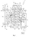
- Corresponding Fig. 1 comprises a piston engine 1, as it can be used in motor vehicles, for. B. an engine block 2, which contains a plurality of cylinders 3, each enclosing a combustion chamber 4 and in which an unspecified piston is arranged strokever plausible.
- an engine block 2 which contains a plurality of cylinders 3, each enclosing a combustion chamber 4 and in which an unspecified piston is arranged strokever plausible.
- Each combustion chamber 4 gas exchange valves, namely intake valves 5 and 6 associated exhaust valves, which are arranged in the engine block 2.
- an intake valve 5 and an exhaust valve 6 are provided per combustion chamber 4. It is clear that two or more intake valves 5 or two or more exhaust valves 6 may also be provided.
- the piston engine 1 is preferably for use as a vehicle drive for commercial vehicles and passenger cars, for example in heavy commercial vehicles such. As construction vehicles and off-road vehicles.
- each cylinder group 3', 3" contains at least one cylinder 3.
- each cylinder group contains 3 ', 3 "three cylinders 3, so a symmetrical division of the six cylinders 3 on the two cylinder groups 3', 3".
- more than two cylinder groups may be present.
- the piston engine 1 has a fresh air system 7, which serves to supply fresh air to the combustion chambers 4.
- the fresh air system 7 a fresh air line 8, which contains a fresh air path 9, the in Fig. 1 indicated by arrows.
- the piston engine 1 is equipped with an exhaust system 10, which serves to carry away exhaust gas from the combustion chambers 4. It has for this purpose an exhaust pipe 11 which contains an exhaust path 12 which is indicated by arrows.
- the piston engine 1 is equipped with an exhaust gas recirculation system 13, with which it is possible to recirculate exhaust gas from the exhaust system 10 to the fresh air system 7.
- the exhaust gas recirculation system 13 has at least one return line 14. In the example, two such return lines 14 are provided. Each return line 14 leads from a removal point or branch point 15 to a discharge point 16. At the respective branch point 15, the respective return line 14 is connected on the input side to the exhaust gas line 11. At the respective introduction point 16, the respective return line 14 is connected to the fresh air line 8.
- the fresh-air system 7 is designed to be double-flowed, at least in a section adjoining the combustion chambers 4, so that the fresh air line 8 has a first flow 8 'for supplying the first three combustion chambers 4 and a second flow 8 "for supplying the second three combustion chambers 4.
- the first fresh air flow 8 ' serves to supply fresh air to the cylinders 3 of the first cylinder group 3', while the second fresh air flow 8 'is provided to supply fresh air to the cylinders 3 of the second cylinder group 3 ".
- the exhaust system 10 is designed to be double-flowed at least in a section adjacent to the combustion chambers 4, so that the exhaust pipe 11 at least in a subsequent to the combustion chambers 4 section the cylinders 3 of the first cylinder group 3 'associated first flood 11' and the cylinders 3 of the second cylinder group 3 "associated second flood 11" has.
- the two exhaust gas recirculation lines 14 Accordingly, each one of these floods 8 ', 8 "and 11', 11" are assigned.
- each return line 14 includes an exhaust gas recirculation cooler 17th
- the piston engine 1 is charged in the illustrated example, so that at least one charging device is provided.
- two charging devices are provided, namely a first charging device 18 and a second charging device 19.
- Both charging devices 18, 19 are configured in the example as an exhaust gas turbocharger.
- the first charging device 18 comprises a first compressor 20, which is arranged in the fresh air line 8 and which is drive-connected via a first drive shaft 21 to a first turbine 22, which is arranged in the exhaust gas line 11.
- the second charging device 19 accordingly comprises a second compressor 23, which is arranged in the fresh air line 8 and is drive-connected via a second drive shaft 24 to a second turbine 25, which is arranged in the exhaust gas line 11.
- the second compressor 23 is arranged downstream of the first compressor 20, while the second turbine 25 is arranged upstream of the first turbine 22.
- a first intercooler 26 may be arranged in the fresh air line 8.
- a second intercooler 27 may be arranged in the fresh air line 8.
- the piston engine 1 is also equipped with at least one additional valve 28.
- two additional valves 28 of this type are provided, namely a first additional valve 28 'and a second additional valve 28 ".
- the respective additional valve 28 is arranged in the fresh air system 7 upstream of the inlet valves 5. In the example, one of these is in the two flows 8', 8" Additional valve 28 is arranged.
- the first additional valve 28 ' is arranged in the first fresh air flood 8', while the second additional valve 28 "in the second Fresh air flow 8 "is arranged .Thus, each additional valve 28 is assigned to three combustion chambers 4.
- the exhaust gas recirculation system 13 can accordingly Fig. 1 be equipped with at least one check valve 51, with the aid of a guided in the respective return line 14, indicated by arrows return path 52 can be locked. Since there is thus no mass flow to the combustion chambers 4 via the exhaust gas recirculation, more air is available.
- At least one of the turbines 22, 25, can accordingly Fig. 1 be configured variable.
- turbines with wastegate 54 or with variable turbine geometry 53 can be used.
- only the second turbine 25 is equipped with such a variable turbine geometry 53.
- the variable turbine geometry 53 makes it possible to change the inflow cross section of the respective turbine 25. In this way, the respective turbine 25 can be kept at an increased rotational speed with a reduced exhaust gas mass flow, so that in the case of a load request the so-called turbo lag, ie the reaction time of the turbine To reduce exhaust gas turbocharger 19.
- variable turbine geometry 53 the back pressure in the exhaust gas upstream of the respective turbine 25 can be increased, whereby the pressure gradient between branch point 15 and discharge point 16 can be increased for the effectiveness of the exhaust gas recirculation system 13.
- fuel consumption increases at the same engine load.
- variable turbine geometry 53 can be actuated to set a comparatively large inflow cross section.
- the exhaust back pressure decreases from.
- a reduction in the exhaust gas recirculation rate which is usually associated with this can be correspondingly achieved by a corresponding phase position of the respective additional valve 28 Fig. 5 be compensated.
- a sufficiently large exhaust gas recirculation rate can be realized even without a backpressure increase via the variable turbine geometry 53.
- the fuel consumption of the internal combustion engine 1 can be reduced.
- Analogous relationships apply to turbines with wastegate 54 since the exhaust gas backpressure influenced by the wastegate 54 controls or influences the exhaust gas recirculation rate.
- the first turbine 22 is equipped with a wastegate 54 for controlling a bypass 55 at least partially bypassing the turbine 22. By closing the wastegate 54, the exhaust gas pressure increases and the exhaust gas recirculation rate increases.
- a supercharged internal combustion engine 1 which has at least one turbine 22 in the exhaust system 10, which is equipped with a wastegate 54 for controlling a bypass 55 at least partially bypassing the turbine 22, the respective wastegate 54 can operate at operating points with reduced load and / or speed be operated so that a relatively large flow cross section for the bypass 55 is established, while the at least one additional valve 28 is operated so that the desired exhaust gas recirculation rate is established.
- One of the turbines 22, 25, here the upstream arranged second turbine 25 may be configured in another embodiment as a twin turbine 47 and have a first inlet 48 and a second inlet 49.
- the first exhaust gas flow 11 ' is connected to the first inlet 48, while the second exhaust gas flow 11 "is connected to the second inlet 49.
- the first cylinder group 3' is a first partial turbine, not shown, of the twin turbine 47 while the second cylinder group 3 "is assigned to a second turbine part of the twin turbine 47 (not shown).
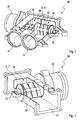
- Fig. 2 shows an example of a closure device 29 having two additional valves 28 which can be actuated via a common drive 30.
- the closure device 29 comprises two gas-tightly separated line sections 31, with which the closure device 29 can be integrated into the two flows 8 ', 8 "of the fresh air system 7.
- the respective additional valve 28 contains in each associated channel section 31 a closure element 32, in which it In the embodiments shown here, this is a flap, which can also be designated 32.
- the closure element 32 can also be another embodiment, eg, a rotary valve
- the closure element 32 designed as a flap can in particular also be referred to as a butterfly flap
- the closure elements 32 and the flaps 32 are rotationally fixedly arranged on a common shaft 33 which is drive-connected to the drive 30.
- the drive 30 is configured to rotate the closure elements 32 so that they are rotating closure elements 32
- the Drehz ahl of the drive 30 and the closure elements 32 may, for example, 3 ⁇ 4 of the speed of an in Fig. 1 indicated crankshaft 34 of the piston engine 1 correspond.
- the closure device 29 may have two separate drives 30 for the two closure elements 32, so that they can be operated independently of each other.
- Fig. 3 shows a further embodiment of such a closure device 29, which differs from the in Fig. 2 shown embodiment, only a single additional valve 28 has. Accordingly, this embodiment also includes only one channel section 31 and a closure element 32, which is arranged in the channel section 31 and is drive-connected to the drive 30 via the shaft 33. Preferably, two such shut-off devices 29 are provided for controlling the two flows 8 ', 8 ", which can be actuated independently of one another.
- FIGS. 2 and 3 embodiments shown illustrate examples of suitable additional valves 28, which can open and lock the respective fresh air path 9 alternately when they are actuated.
- the respective closure element 32 rotates during operation of the piston engine 1, wherein it passes through a closed position twice with each complete revolution, while it is open between two successive closed positions.
- the time interval between two successive closed positions or closing phases defines a switching frequency of the respective additional valve 28.
- the respective additional valve 28 is operated synchronously to the crankshaft 34, so that at least during a stationary actuation of the respective additional valve 28, a constant correlation between the rotational speed of the crankshaft 34 and the switching frequency of the respective additional valve 28 is present.
- the closure element 32 rotates at the same or at twice or at three times the speed of the crankshaft 34.
- crankshaft 34 and auxiliary valve 28 or closure element 32 will be described with reference to the diagram of FIG Fig. 4 explained in more detail.
- the abscissa shows the crankshaft angle in degrees, in short ° KWW.
- the ordinate shows the stroke of the gas exchange valves 5, 6.
- An exhaust valve elevation curve 35 is inscribed in the diagram and an intake valve elevation curve 36.
- the two elevation curves 35, 36 overlap in a small area.
- the associated intersection is specifically arranged at 0 ° KWW and otherwise corresponds to a top dead center of a piston movement of the combustion chamber 4 associated piston.
- the diagram contains the Fig. 4 in the form of a vertical line, a closing time 37 of the additional combustion chamber 4 associated with the considered combustion chamber 4, which in Fig. 4 is also shown symbolically for illustration.
- This closing time 37 is always at a stationary actuation of the additional valve 28 in the same relation to the crankshaft 34, so it is always at the same crankshaft angle.
- the closing time 37 is at about 150 ° KWW.
- the relative position of the closing time 37 relative to the crankshaft angle of the crankshaft 34 defines a phase relationship between the auxiliary valve 28 and the associated rotating closure element 32 and a reference defined by the relative rotational position of the crankshaft 34. This reference is in particular a reference time or a reference frequency or reference speed.
- this phase position is adjustable.
- the closing time 37 ie the phase position of the closure element 32 is relative to the reference, so relative to the rotational position of the crankshaft 34 both in the direction of smaller crankshaft angle and in the direction of larger crankshaft angle adjustable, so the phase position between additional valve 28 and crankshaft 34 and between the closure element 32nd and reference value.
- An arrow 39 indicates that the closing time 37, for example, from an initial phase position, in which the closing time 37 is 0 ° KWW, so congruent to the ordinate, is displaceable to the position shown, in which the closing time 37 at about 150 ° KWW lies. It is clear that in principle Even larger crankshaft angle for the closing time 37 are adjustable, z. B. can be provided up to 240 ° KWW adjustability.
- a curve 40 indicates the control movement of the closure element 32 in the respective flow channel.
- the closure member 32 is opened while being closed at position 42.
- the closure element 32 releases the flow-through cross-section of the associated flow channel more or less freely.
- the closure element 32 blocks the flow-through cross-section of the respective flow channel.
- FIG. 5 are symbolically three closure means 29 indicated to symbolize the associated positions of the closure element 32.
- the controllable with the help of the closure element 32 souströmbare cross section is denoted by 43.
- the flow channel is formed, for example, by the fresh air channel 8 or by one of its channels 8 ', 8 "Alternatively, the flow channel in another embodiment can also be the exhaust channel 11 or one of its channels 11', 11". Likewise, an embodiment is possible in which the flow channel is formed by one of the return channels 14. Likewise, any combinations of the above variants are conceivable.
- a curve 44 indicates the course of a drive torque acting on it for driving the closure element 32, depending on the rotational position of the closure element 32.
- the drive torques acting on the closure element 32 fluctuate about an average moment 45, so that, based on the mean moment, 45 larger moments and smaller moments occur.
- the mean moment 45 has a positive value. at In other embodiments, the mean moment 45 may also be neutral, that is, have the value 0. In particular, negative moments can then also act on the closure element 32.
- the torques applied to the ordinate are the drive torques to be applied by the closure element drive 30, which are required to compensate for the flow moments acting on the closure element 32.
- Fig. 6 5 again shows a simplified curve 44 'for illustrating the flow torque profile at the closure element 32.
- the mean moment 45' has the value 0.
- negative flow moments correspond to braking or retarding flow forces on the closure element 32.
- the flow forces or flow moments acting on the closure element 32 can be used to accelerate or decelerate the closure element 32.
- a temporary, short-term acceleration of the closure element 32 leads to a shift of the phase position of the closure element 32 relative to the reference or relative to the crankshaft angle of the crankshaft 34 to early. Based on 0 ° KWW locks the closure element 32 then earlier.
- a temporary, brief braking of the closure element 32 leads to a shift of the phase position relative to the reference or relative to the angle of the crankshaft 34 to late. With reference to 0 ° KWW, the shutter member 32 then locks later.
- Fig. 6 symbolizes a curve 56 an increase in the phase angle, ie an adjustment of the phase position to late.
- braking or deceleration of the closure element 32 takes place in a rotation angle region 57.
- this delay region 57 lies in a region of the flow moment curve 44 'in which negative moments are present relative to the mean moment 45'. This means that braking or retarding flow forces act on the closure element 32 here. As a result, these flow forces or flow moments for delaying the closure element 32 can be exploited.
- this delay phase is very short in time and only extends over a few degrees KWW, in particular over less than 30 ° KWW.
- a further curve 58 indicates a reduction of the phase angle, ie an adjustment of the phase position to early.
- the closure element 32 is briefly accelerated in a rotation angle range 59.
- This accelerating rotation angle range 59 can be recognized with reference to FIG Flow torque curve 44 'placed on the closure member 32 so that there positive moments with respect to the average torque 45 are present.
- this acceleration of the closure element 32 likewise takes place in a temporally short section or in a small crank angle region. For example, this acceleration phase is less than 30 ° KWW.
- the proposed operating method makes use of the fluctuating forces or moments acting on the closure element 32 between maximum values and minimum values.
- An acceleration of the closure element 32 is carried out in the region of the minimum values, since here the smallest opposing forces or counter torques on the closure element 32 act.
- the forces or moments acting on the closure element 32 can also be negative, so that they themselves cause an acceleration of the closure element 32.
- the braking of the closure element 32 is expediently carried out in the region of the maximum forces or moments, so that the rotational resistance generated by the flow forces or flow moments can already make a significant contribution to the braking of the closure element 32.
- the acceleration of the closure element 32 takes place in a rotation angle range in which the closure element 32 opens the associated flow cross-section 43 to a maximum. It has been found that the forces acting on the closure element 32 are minimal in this rotation angle range. In contrast, the temporary deceleration of the closure element 32 takes place in a rotation angle range in which the closure element 32 blocks the associated flow cross-section 43 to a maximum. It has been shown that in this rotation angle range, the largest forces or moments counteracting the movement of the closure element can be expected.
- a rotary position recognition device 50 For determining the relative rotational position of the closure element 32 may accordingly Fig. 1 at least one rotary position recognition device 50 may be provided.
- a rotational position detection device 50 In coupled closure elements 32, as in the in Fig. 2 shown embodiment, a rotational position detection device 50 is sufficient.
- the respective rotational position detection device 50 cooperates with a control device 46, which in Fig. 1 also shown simplified.
- the control device 46 is designed or programmed such that it is suitable for operating the additional valves 28 or the closure devices 29. In particular, the control device 46 can carry out the operating methods explained above and those yet to be explained below.
- control device 46 can take into account the relative rotational position of the closure elements 32 that it receives in the respective rotational position detection device 50.
- FIGS. 7 and 8 show two fundamentally different designs for the closure device 29. It shows Fig. 7 an embodiment without recess while Fig. 8 an embodiment with a recess 60 shows. Said recess 60 is in a wall of the respective flow channel, z. Ex. Of the fresh air duct 8, incorporated. In this recess 60, the closure element designed as a flap 32 emerges due to its rotation during a predetermined, limited rotation angle range. This rotation angle range can be, for example, 90 °. The recess 60 allows an enlargement of the closing angle range. While the closure element 32 in the in Fig. 7 shown embodiment without recess 60 has a very small closing angle range, the in Fig. 8 reproduced embodiment with recess 60 a significantly larger closing angle range.
- FIGS. 9 and 10 show diagrams in which the ordinate indicates the free flow-through cross section 43 from 0% to 100%, while the abscissa the pivot angle of the closure element 32 in a range of 0 ° (perpendicular to the flow direction 61) to 90 ° (parallel to the flow direction 61) indicates.
- Fig. 9 belongs to the embodiment according to Fig. 7 without indentation 60 while Fig. 10 to the embodiment according to Fig. 8 heard with depression 60.
- the maintenance of a desired phase position can now be realized with the aid of the control device 46 such that the phase position is controlled only in at least one predetermined rotation angle range, while otherwise only one control of the rotation speed, that is to say a position control, is performed in all other rotation angle ranges becomes.
- the drive 30 is formed by an electric motor
- the rotational speed of the closure element 32 by the energization of the electric drive 30 determines. By changing the energization, the rotational speed of the closure element 32 can thus be changed.
- the control device 46 can be configured such that it regulates the energization of the electric drive 30 only in at least one predetermined rotational angle range of the closure element 32 Incidentally controls the energization, that is set to one of the desired rotational speed associated value of the energization.
- the control or regulation of the energization effects a regulation of the rotational speed of the closure element 32.
- Such a control of the energization can be implemented extremely easily in contrast to the regulation and is associated with comparatively little energy consumption.
- the phase angle of the closure element 32 can vary during this speed control, since the speed control itself can not directly compensate for the forces or moments acting on the closure element 32.
- the regulation of the phase positions or the position regulation makes it possible to correct the phase position in order to be able to compensate or compensate for the phase deviation arising on the closure element 32 due to the forces or moments acting thereon.
- FIGS. 9 and 10 are rotational angle ranges 62 marked, in which it depends on the maintenance of the desired phase angle between closure element 32 and reference size or crankshaft 34 and in which the control of the phase angle is performed. In the example, these are in each case rotational angle ranges in which the closure element 32 extends out of its closing angle range. In Fig. 9 this is an area adjoining 0 ° rotation angle. In Fig. 10 is this a range of angles of rotation offset by a value 63 from 0 ° rotation angle. The value 63 defines half the rotation angle range of the recess 60.
- rotational angle ranges 64 are marked in which the maintenance of the phase position is unimportant.
- the control of the phase position takes place in the rotation angle ranges 62. In all other rotation angles, a control of the phase position may be sufficient.
- control of the phase position is thus at the end of the closing angle range of the closure element 32.
- control of the phase position at the beginning of the closing angle range of the respective closure element 32 take place, whereby the beginning of the closing is defined.
- control extends over the entire closing angle range, including an entry phase and an exit phase.
- control or control of the phase position can be provided to comply with the observance of a desired actual phase position over the entire rotation angle range of the closure element 32 by means of a position control.
- a position control it is additionally provided to modulate the desired phase position as a function of the flow forces and / or flow torques acting on the closure element 32 as well as on the current angle of rotation position 32.
- the modulation of the setpoint values for the phase angle takes into account the forces or torques on the closure element 32 which vary as a function of the rotational angle position 32 and can thereby generate a desired value profile which results in a minimum energy requirement for position regulation.
- the modulation of the setpoint values in the direction of small target / actual deviations can be useful at least at the beginning and / or end of a Closed angle range done in which the closure element 32 blocks the flow-through cross section 43, or over the entire closing angle range.
- control or control of the phase position can be provided to comply with the observance of a desired actual phase position over the entire rotation angle range of the closure element 32 as before again by means of a position control.
- the permanent position control is additionally provided, a range of permissible deviations that occur between the actual phase position and the desired phase position, but trigger no control intervention, depending on the acting on the closure element 32 flow forces and / or flow moments and depending on the modulate current angular position 32.
- the modulation of the range of permissible nominal-actual deviations for the phase position takes into account the forces or moments that vary depending on the rotational angle position 32 on the closure element 32 and can thereby generate a profile for this admissibility range, which results in a minimum energy requirement for position control.
- This range of admissibility is varied so that in the regions of the rotational movement of the closure element 32, which only have to meet low position requirements, the permissible deviations are relatively large.
- the modulation of the admissibility range in the direction of small target-actual deviations can take place at least at the beginning and / or end of a closing angle range in which the closure element 32 blocks the flow-through cross section 43, or over the entire closing angle range.
- control or control of the phase position may also be provided that Maintaining a desired actual phase position over the entire rotation angle range of the closure element 32 as before to realize again by means of a position control.
- the permanent position control is additionally provided, parameters of the control, ie control parameters and / or parameters of a controller used for control, ie controller parameters which determine the reaction of the control or the controller to a desired-actual deviation, depending on to modulate the flow forces and / or flow moments acting on the closure element 32 as well as dependent on the current rotation angle position 32.
- the modulation of the control parameters or the controller parameters takes into account the forces or torques on the closure element 32 which vary as a function of the rotational angle position 32 and can thereby generate a profile for this admissibility range, which results in a minimum energy requirement for position control.
- the control parameters are varied so that in the areas of the rotational movement of the closure element 32, which only have to meet low position requirements, the control actions performed are relatively small or weak.
- the modulation of the control parameters in the direction of small target-actual deviations at least at the beginning and / or at the end of a closing angle range can take place in which the closure element 32 blocks the flow-through cross-section 43, or over the entire closing angle range.
- closure device 29 is preferably used in a fresh air channel 8 or in a fresh air flow 8 ', 8 ", in other embodiments it is also possible to use a flow channel in which the closure device 29 is used Exhaust duct 11 or through an exhaust gas flow 11 ', 11 "to form, wherein the respective closure element 32 is then arranged downstream of exhaust valves 6.
- further measures can be carried out, for example in order to specifically influence the forces or torques acting on the closure element 32.
- a corresponding shape of the designed as a flap 32 closure member 32 can be mitigated by a corresponding shape of the designed as a flap 32 closure member 32, the strength of the alternating torque, which occurs when the flap 32 exceeds the zero position in the central axis of the respective flow channel.
- the thicker the shaft 33 of the flap 32 the stronger the envelope area can be distributed to larger angle values, whereby the strong torque change is less abrupt.
- a contouring of the flap 32 is conceivable, for.
Landscapes
- Engineering & Computer Science (AREA)
- Chemical & Material Sciences (AREA)
- Combustion & Propulsion (AREA)
- Mechanical Engineering (AREA)
- General Engineering & Computer Science (AREA)
- Output Control And Ontrol Of Special Type Engine (AREA)
Claims (15)
- Procédé de fonctionnement d'au moins un élément d'obturation rotatif (32), qui ouvre et bloque alternativement dans un canal d'écoulement (8) une section transversale (43) traversée par un écoulement relativement à une grandeur de référence avec une position de phase réglable, dans lequel afin de varier la position de phase les forces d'écoulement agissant sur l'élément d'obturation (32) et/ou les couples d'écoulement sont utilisés pour une accélération ou un freinage temporaire de l'élément d'obturation (32).
- Procédé selon la revendication 1, caractérisé en ce que- les forces d'écoulement et/ou les couples d'écoulement d'entraînement agissant sur l'élément d'obturation (3) sont utilisés pour décaler prématurément la position de phase, et/ou- les forces d'écoulement et/ou les couples d'écoulement de freinage agissant sur l'élément d'obturation (32) sont utilisés pour décaler postérieurement la position de phase.
- Procédé selon les revendications 1 ou 2, caractérisé en ce que- l'accélération temporaire de l'élément d'obturation (32) a lieu dans une plage d'angle de rotation, dans laquelle des forces d'écoulement d'entraînement et/ou des couples d'écoulement agissent sur l'élément d'obturation (32), et/ou- le freinage temporaire de l'élément d'obturation (32) a lieu dans une plage d'angle de rotation, dans laquelle des forces d'écoulement de freinage et/ou des couples d'écoulement agissent sur l'élément d'obturation (32).
- Procédé selon une des revendications 1 à 3, caractérisé en ce que- l'accélération temporaire de l'élément d'obturation (32) a lieu dans une plage d'angle de rotation, dans laquelle l'élément d'obturation (32) produit une ouverture maximale de la section transversale (43) traversée par un écoulement, et/ou- le freinage temporaire de l'élément d'obturation (32) a lieu dans une plage d'angle de rotation, dans laquelle l'élément d'obturation (32) produit un blocage maximal de la section transversale (43) traversée par un écoulement.
- Procédé selon une des revendications 1 à 4, caractérisé en ce que- le canal d'écoulement est prévu afin d'alimenter du gaz frais dans un moteur à piston (1) ou d'évacuer du gaz d'échappement d'un moteur à piston (1) ou de réintroduire du gaz d'échappement dans un moteur à piston (1),- la grandeur de référence est définie par l'angle de rotation d'un vilebrequin (34) du moteur à piston (1).
- Procédé selon une des revendications 1 à 5, caractérisé en ce que une position de rotation relative de l'élément d'obturation (32) est déterminée au moyen d'un dispositif de reconnaissance de position de rotation (50) et est pris en compte par un dispositif de commande (46) coopérant avec le dispositif de reconnaissance de position de rotation (50) pour varier la position de phase.
- Procédé selon une des revendications 1 à 6, caractérisé en ce que pour entraîner l'élément d'obturation (32) un moteur électrique est employé, dont l'alimentation en courant est variée afin de régler la vitesse de rotation et/ou l'angle de rotation de l'élément d'obturation (32).
- Procédé selon une des revendications 1 à 7, caractérisé en ce que le maintien d'une position de phase souhaitée a lieu seulement dans au moins une plage d'angle de rotation prédéterminée au moyen d'une régulation de l'angle de rotation de l'élément d'obturation (32) et du reste au moyen d'une régulation de la vitesse de rotation de l'élément d'obturation (32).
- Procédé selon la revendication 8, caractérisé en ce que la régulation a lieu au moins au début et/ou à la fin d'une plage d'angle de fermeture, dans laquelle l'élément d'obturation (32) bloque la section transversale traversée par un écoulement (43).
- Procédé selon une des revendications 1 à 7, caractérisé en ce que le maintien d'une position de phase effective souhaitée a lieu au moyen d'une régulation sur la totalité de la plage d'angle de rotation de l'élément d'obturation (32), dans lequel une position de phase de consigne est modulée en fonction des forces d'écoulement agissant sur l'élément d'obturation (32) et/ou des couples d'écoulement et/ou en fonction de la position d'angle de rotation de l'élément d'obturation (32).
- Procédé selon une des revendications 1 à 7, caractérisé en ce que le maintien d'une position de phase effective souhaitée a lieu au moyen d'une régulation sur la totalité de la plage d'angle de rotation de l'élément d'obturation (32), dans lequel une plage d'écarts autorisés est modulée par une position de phase de consigne en fonction des forces d'écoulement agissant sur l'élément d'obturation (32) et/ou des couples d'écoulement et/ou en fonction de la position d'angle de rotation de l'élément d'obturation (32).
- Procédé selon une des revendications 1 à 7, caractérisé en ce que le maintien d'une position de phase effective souhaitée a lieu au moyen d'une régulation sur la totalité de la plage d'angle de rotation de l'élément d'obturation (32), dans lequel les paramètres de régulation sont modulés en fonction des forces d'écoulement agissant sur l'élément d'obturation (32) et/ou les couples d'écoulement et/ou en fonction de la position d'angle de rotation de l'élément d'obturation (32).
- Procédé selon une des revendications 10 à 12, caractérisé en ce que la modulation a lieu au moins au début et/ou à la fin d'une plage d'angle de fermeture, en ce que l'élément d'obturation (32) bloque la section transversale traversée par un écoulement (43).
- Procédé selon une des revendications 1 à 13, caractérisé en ce que- le canal d'écoulement est un canal d'air frais (8) d'un moteur à piston (1), dans lequel l'élément d'obturation (32) est disposé en amont de soupapes d'admission (5) pour commander des processus d'échange de gaz, et/ou- le canal d'écoulement est un canal de gaz d'échappement (11) d'un moteur à piston (1), dans lequel l'élément d'obturation (32) est disposé en aval de soupapes d'échappement (6) pour commander des processus d'échange de gaz, et/ou- le canal d'écoulement est un canal de réintroduction de gaz d'échappement d'un moteur à piston (1), dans lequel l'élément d'obturation (32) est disposé entre un emplacement de prélèvement du côté de l'air frais et un emplacement d'introduction du côté des gaz d'échappement pour commander les taux de réintroduction de gaz d'échappement.
- Dispositif d'obturation pour commander un canal d'écoulement, notamment d'un moteur à piston (1),- comportant au moins un élément d'obturation (32) entraîné rotativement en fonctionnement pour ouvrir et bloquer alternativement d'une section transversale traversée par un écoulement (43) du canal d'écoulement,- comportant une unité de commande (46) pour actionner un entraînement (30) de l'élément d'obturation (32), qui est conçue et/ou programmée de telle sorte qu'elle puisse actionner le dispositif d'obturation (29) afin de mettre en oeuvre un procédé de fonctionnement selon une des revendications 1 à 14.
Applications Claiming Priority (1)
| Application Number | Priority Date | Filing Date | Title |
|---|---|---|---|
| DE102009036192A DE102009036192A1 (de) | 2009-08-05 | 2009-08-05 | Verschlusseinrichtung und Betriebsverfahren |
Publications (2)
| Publication Number | Publication Date |
|---|---|
| EP2295770A1 EP2295770A1 (fr) | 2011-03-16 |
| EP2295770B1 true EP2295770B1 (fr) | 2013-03-20 |
Family
ID=42732756
Family Applications (1)
| Application Number | Title | Priority Date | Filing Date |
|---|---|---|---|
| EP20100169990 Not-in-force EP2295770B1 (fr) | 2009-08-05 | 2010-07-19 | Dispositif de fermeture et procédé de fonctionnement |
Country Status (3)
| Country | Link |
|---|---|
| US (1) | US8201541B2 (fr) |
| EP (1) | EP2295770B1 (fr) |
| DE (1) | DE102009036192A1 (fr) |
Families Citing this family (5)
| Publication number | Priority date | Publication date | Assignee | Title |
|---|---|---|---|---|
| DE102008046596A1 (de) * | 2008-07-18 | 2010-01-21 | Mahle International Gmbh | Frischluftanlage |
| DE102010061859A1 (de) * | 2010-11-24 | 2012-05-24 | Mahle International Gmbh | Betriebsverfahren |
| EP2626531A1 (fr) * | 2012-02-08 | 2013-08-14 | Ford Global Technologies, LLC | Moteur à combustion interne à plusieurs cylindres et procédé de fonctionnement d'un tel moteur à combustion interne à plusieurs cylindres |
| CN106931223B (zh) * | 2015-12-31 | 2019-09-17 | 中国核动力研究设计院 | 一种部分回转全封闭电传动装置防卡滞方法 |
| US11149657B2 (en) * | 2019-12-04 | 2021-10-19 | Mikuni Corporation | Throttle device |
Family Cites Families (10)
| Publication number | Priority date | Publication date | Assignee | Title |
|---|---|---|---|---|
| JPS6312827A (ja) * | 1986-07-02 | 1988-01-20 | Nissan Motor Co Ltd | 内燃機関の吸気制御装置 |
| DE3737823A1 (de) * | 1987-11-06 | 1989-08-10 | Schatz Oskar | Verfahren zum betrieb eines verbrennungsmotors und verbrennungsmotor zur durchfuehrung des verfahrens |
| US5105784A (en) * | 1991-04-08 | 1992-04-21 | General Motors Corporation | Rotary valve and system for duration and phase control |
| DE4414849A1 (de) * | 1994-04-28 | 1995-11-02 | Ingelheim Peter Graf Von | Fluidregelsystem für Kolbenmaschinen, insbesondere Verbrennungsmotoren nach dem Otto-Prozeß |
| DE19830575A1 (de) * | 1998-07-08 | 2000-01-13 | Nonox B V | Ladungssteuervorrichtung für eine sowie Verfahren zum Steuern des Betriebs einer Hubkolbenbrennkraftmaschine |
| DE10240913A1 (de) * | 2002-09-04 | 2004-03-18 | Schatz Thermo Engineering | Verbrennungsmotor der Kolbenbauart und Verfahren zu seinem Betrieb |
| DE102006015589A1 (de) * | 2006-03-31 | 2007-10-04 | Mahle International Gmbh | Frischgasanlage und Betriebsverfahren für einen Kolbenmotor |
| DE102006037934A1 (de) * | 2006-08-11 | 2008-02-14 | Mahle International Gmbh | Brennkraftmaschine |
| DE102007004264A1 (de) * | 2007-01-23 | 2008-07-24 | Mahle International Gmbh | Brennkraftmaschine |
| DE102007047728A1 (de) * | 2007-10-05 | 2008-11-06 | Rudolf Huttary | Verbrennungsmaschine mit variabler synchroner Gaswechselsteuerung |
-
2009
- 2009-08-05 DE DE102009036192A patent/DE102009036192A1/de not_active Withdrawn
-
2010
- 2010-07-19 EP EP20100169990 patent/EP2295770B1/fr not_active Not-in-force
- 2010-08-04 US US12/850,285 patent/US8201541B2/en not_active Expired - Fee Related
Also Published As
| Publication number | Publication date |
|---|---|
| US20110036412A1 (en) | 2011-02-17 |
| DE102009036192A1 (de) | 2011-02-17 |
| EP2295770A1 (fr) | 2011-03-16 |
| US8201541B2 (en) | 2012-06-19 |
Similar Documents
| Publication | Publication Date | Title |
|---|---|---|
| EP2267291A2 (fr) | Moteur à piston et méthode d'opération | |
| EP2412955B1 (fr) | Procédé de freinage moteur | |
| EP2049779B1 (fr) | Moteur à combustion | |
| EP2208875B1 (fr) | Dispositif de soupape et moteur à combustion interne. | |
| EP2295770B1 (fr) | Dispositif de fermeture et procédé de fonctionnement | |
| EP2372125B1 (fr) | Dispositif d'alimentation en gaz frais pour un moteur à combustion interne doté d'une turbosoufflante de gaz d'échappement et son procédé de commande | |
| EP2333289B1 (fr) | Système moteurs à combustion interne et procédé de fonctionnnement associé | |
| DE102005012306A1 (de) | Verfahren zum Betrieb einer Brennkraftmaschine und Brennkraftmaschine hierzu | |
| EP2122137B1 (fr) | Système de moteur à combustion interne | |
| EP2183469B1 (fr) | Moteur à piston | |
| WO2012069376A2 (fr) | Procédé de fonctionnement | |
| DE102005002246A1 (de) | Brennkraftmaschine mit einer Abgasrückführungseinrichtung und Verfahren zum Betrieb einer Brennkraftmaschine | |
| EP2049774A1 (fr) | Moteur à combustion interne | |
| DE102012023118A1 (de) | Verbrennungskraftmaschine für einen Kraftwagen | |
| EP3004585B1 (fr) | Procédé servant à faire fonctionner un moteur à explosion | |
| EP2166211B1 (fr) | Moteur à combustion interne avec recirculation des gaz d'échappement | |
| EP2427647A1 (fr) | Moteur à combustion interne et procédé de fonctionnement associé | |
| DE102015204155B3 (de) | Verfahren zur momentenneutralen Umschaltung von Betriebszuständen eines Aktuators einer Brennkraftmaschine | |
| EP2504535A1 (fr) | Dispositif d'ajustement variable des temps de commande de soupapes d'échange des gaz d'un moteur à combustion interne | |
| DE10250771B4 (de) | Motorbremseinrichtung und Verfahren zu deren Steuerung | |
| DE102007025178B4 (de) | Brennkraftmaschinensystem mit externer Abgasrückführung | |
| DE102007025179A1 (de) | Brennkraftmaschinensystem | |
| WO2012069377A1 (fr) | Procédé de fonctionnement | |
| DE102017113522A1 (de) | Aufgeladene Brennkraftmaschine | |
| DE102013215764A1 (de) | Hubkolbenbrennkraftmaschine sowie Verfahren zur Steuerung der Einlassseite einer Hubkolbenbrennkraftmaschine |
Legal Events
| Date | Code | Title | Description |
|---|---|---|---|
| PUAI | Public reference made under article 153(3) epc to a published international application that has entered the european phase |
Free format text: ORIGINAL CODE: 0009012 |
|
| AK | Designated contracting states |
Kind code of ref document: A1 Designated state(s): AL AT BE BG CH CY CZ DE DK EE ES FI FR GB GR HR HU IE IS IT LI LT LU LV MC MK MT NL NO PL PT RO SE SI SK SM TR |
|
| AX | Request for extension of the european patent |
Extension state: BA ME RS |
|
| 17P | Request for examination filed |
Effective date: 20110727 |
|
| GRAP | Despatch of communication of intention to grant a patent |
Free format text: ORIGINAL CODE: EPIDOSNIGR1 |
|
| GRAS | Grant fee paid |
Free format text: ORIGINAL CODE: EPIDOSNIGR3 |
|
| GRAA | (expected) grant |
Free format text: ORIGINAL CODE: 0009210 |
|
| AK | Designated contracting states |
Kind code of ref document: B1 Designated state(s): AL AT BE BG CH CY CZ DE DK EE ES FI FR GB GR HR HU IE IS IT LI LT LU LV MC MK MT NL NO PL PT RO SE SI SK SM TR |
|
| REG | Reference to a national code |
Ref country code: GB Ref legal event code: FG4D Free format text: NOT ENGLISH |
|
| REG | Reference to a national code |
Ref country code: CH Ref legal event code: EP |
|
| REG | Reference to a national code |
Ref country code: IE Ref legal event code: FG4D Free format text: LANGUAGE OF EP DOCUMENT: GERMAN |
|
| REG | Reference to a national code |
Ref country code: AT Ref legal event code: REF Ref document number: 602228 Country of ref document: AT Kind code of ref document: T Effective date: 20130415 |
|
| REG | Reference to a national code |
Ref country code: DE Ref legal event code: R096 Ref document number: 502010002596 Country of ref document: DE Effective date: 20130516 |
|
| PG25 | Lapsed in a contracting state [announced via postgrant information from national office to epo] |
Ref country code: LT Free format text: LAPSE BECAUSE OF FAILURE TO SUBMIT A TRANSLATION OF THE DESCRIPTION OR TO PAY THE FEE WITHIN THE PRESCRIBED TIME-LIMIT Effective date: 20130320 Ref country code: ES Free format text: LAPSE BECAUSE OF FAILURE TO SUBMIT A TRANSLATION OF THE DESCRIPTION OR TO PAY THE FEE WITHIN THE PRESCRIBED TIME-LIMIT Effective date: 20130701 Ref country code: SE Free format text: LAPSE BECAUSE OF FAILURE TO SUBMIT A TRANSLATION OF THE DESCRIPTION OR TO PAY THE FEE WITHIN THE PRESCRIBED TIME-LIMIT Effective date: 20130320 Ref country code: NO Free format text: LAPSE BECAUSE OF FAILURE TO SUBMIT A TRANSLATION OF THE DESCRIPTION OR TO PAY THE FEE WITHIN THE PRESCRIBED TIME-LIMIT Effective date: 20130620 Ref country code: BG Free format text: LAPSE BECAUSE OF FAILURE TO SUBMIT A TRANSLATION OF THE DESCRIPTION OR TO PAY THE FEE WITHIN THE PRESCRIBED TIME-LIMIT Effective date: 20130620 |
|
| REG | Reference to a national code |
Ref country code: LT Ref legal event code: MG4D |
|
| PG25 | Lapsed in a contracting state [announced via postgrant information from national office to epo] |
Ref country code: GR Free format text: LAPSE BECAUSE OF FAILURE TO SUBMIT A TRANSLATION OF THE DESCRIPTION OR TO PAY THE FEE WITHIN THE PRESCRIBED TIME-LIMIT Effective date: 20130621 Ref country code: LV Free format text: LAPSE BECAUSE OF FAILURE TO SUBMIT A TRANSLATION OF THE DESCRIPTION OR TO PAY THE FEE WITHIN THE PRESCRIBED TIME-LIMIT Effective date: 20130320 Ref country code: SI Free format text: LAPSE BECAUSE OF FAILURE TO SUBMIT A TRANSLATION OF THE DESCRIPTION OR TO PAY THE FEE WITHIN THE PRESCRIBED TIME-LIMIT Effective date: 20130320 Ref country code: FI Free format text: LAPSE BECAUSE OF FAILURE TO SUBMIT A TRANSLATION OF THE DESCRIPTION OR TO PAY THE FEE WITHIN THE PRESCRIBED TIME-LIMIT Effective date: 20130320 |
|
| REG | Reference to a national code |
Ref country code: NL Ref legal event code: VDEP Effective date: 20130320 |
|
| PG25 | Lapsed in a contracting state [announced via postgrant information from national office to epo] |
Ref country code: HR Free format text: LAPSE BECAUSE OF FAILURE TO SUBMIT A TRANSLATION OF THE DESCRIPTION OR TO PAY THE FEE WITHIN THE PRESCRIBED TIME-LIMIT Effective date: 20130320 |
|
| PG25 | Lapsed in a contracting state [announced via postgrant information from national office to epo] |
Ref country code: EE Free format text: LAPSE BECAUSE OF FAILURE TO SUBMIT A TRANSLATION OF THE DESCRIPTION OR TO PAY THE FEE WITHIN THE PRESCRIBED TIME-LIMIT Effective date: 20130320 Ref country code: IS Free format text: LAPSE BECAUSE OF FAILURE TO SUBMIT A TRANSLATION OF THE DESCRIPTION OR TO PAY THE FEE WITHIN THE PRESCRIBED TIME-LIMIT Effective date: 20130720 Ref country code: NL Free format text: LAPSE BECAUSE OF FAILURE TO SUBMIT A TRANSLATION OF THE DESCRIPTION OR TO PAY THE FEE WITHIN THE PRESCRIBED TIME-LIMIT Effective date: 20130320 Ref country code: CZ Free format text: LAPSE BECAUSE OF FAILURE TO SUBMIT A TRANSLATION OF THE DESCRIPTION OR TO PAY THE FEE WITHIN THE PRESCRIBED TIME-LIMIT Effective date: 20130320 Ref country code: RO Free format text: LAPSE BECAUSE OF FAILURE TO SUBMIT A TRANSLATION OF THE DESCRIPTION OR TO PAY THE FEE WITHIN THE PRESCRIBED TIME-LIMIT Effective date: 20130320 Ref country code: PT Free format text: LAPSE BECAUSE OF FAILURE TO SUBMIT A TRANSLATION OF THE DESCRIPTION OR TO PAY THE FEE WITHIN THE PRESCRIBED TIME-LIMIT Effective date: 20130722 Ref country code: SK Free format text: LAPSE BECAUSE OF FAILURE TO SUBMIT A TRANSLATION OF THE DESCRIPTION OR TO PAY THE FEE WITHIN THE PRESCRIBED TIME-LIMIT Effective date: 20130320 |
|
| PG25 | Lapsed in a contracting state [announced via postgrant information from national office to epo] |
Ref country code: PL Free format text: LAPSE BECAUSE OF FAILURE TO SUBMIT A TRANSLATION OF THE DESCRIPTION OR TO PAY THE FEE WITHIN THE PRESCRIBED TIME-LIMIT Effective date: 20130320 Ref country code: CY Free format text: LAPSE BECAUSE OF FAILURE TO SUBMIT A TRANSLATION OF THE DESCRIPTION OR TO PAY THE FEE WITHIN THE PRESCRIBED TIME-LIMIT Effective date: 20130320 |
|
| PLBE | No opposition filed within time limit |
Free format text: ORIGINAL CODE: 0009261 |
|
| STAA | Information on the status of an ep patent application or granted ep patent |
Free format text: STATUS: NO OPPOSITION FILED WITHIN TIME LIMIT |
|
| BERE | Be: lapsed |
Owner name: MAHLE INTERNATIONAL G.M.B.H. Effective date: 20130731 |
|
| PG25 | Lapsed in a contracting state [announced via postgrant information from national office to epo] |
Ref country code: DK Free format text: LAPSE BECAUSE OF FAILURE TO SUBMIT A TRANSLATION OF THE DESCRIPTION OR TO PAY THE FEE WITHIN THE PRESCRIBED TIME-LIMIT Effective date: 20130320 |
|
| 26N | No opposition filed |
Effective date: 20140102 |
|
| PG25 | Lapsed in a contracting state [announced via postgrant information from national office to epo] |
Ref country code: MC Free format text: LAPSE BECAUSE OF FAILURE TO SUBMIT A TRANSLATION OF THE DESCRIPTION OR TO PAY THE FEE WITHIN THE PRESCRIBED TIME-LIMIT Effective date: 20130320 Ref country code: IT Free format text: LAPSE BECAUSE OF FAILURE TO SUBMIT A TRANSLATION OF THE DESCRIPTION OR TO PAY THE FEE WITHIN THE PRESCRIBED TIME-LIMIT Effective date: 20130320 |
|
| REG | Reference to a national code |
Ref country code: DE Ref legal event code: R097 Ref document number: 502010002596 Country of ref document: DE Effective date: 20140102 |
|
| REG | Reference to a national code |
Ref country code: IE Ref legal event code: MM4A |
|
| PG25 | Lapsed in a contracting state [announced via postgrant information from national office to epo] |
Ref country code: BE Free format text: LAPSE BECAUSE OF NON-PAYMENT OF DUE FEES Effective date: 20130731 |
|
| PG25 | Lapsed in a contracting state [announced via postgrant information from national office to epo] |
Ref country code: IE Free format text: LAPSE BECAUSE OF NON-PAYMENT OF DUE FEES Effective date: 20130719 |
|
| PGFP | Annual fee paid to national office [announced via postgrant information from national office to epo] |
Ref country code: FR Payment date: 20140729 Year of fee payment: 5 Ref country code: GB Payment date: 20140729 Year of fee payment: 5 |
|
| REG | Reference to a national code |
Ref country code: CH Ref legal event code: PL |
|
| PG25 | Lapsed in a contracting state [announced via postgrant information from national office to epo] |
Ref country code: LI Free format text: LAPSE BECAUSE OF NON-PAYMENT OF DUE FEES Effective date: 20140731 Ref country code: CH Free format text: LAPSE BECAUSE OF NON-PAYMENT OF DUE FEES Effective date: 20140731 |
|
| PG25 | Lapsed in a contracting state [announced via postgrant information from national office to epo] |
Ref country code: SM Free format text: LAPSE BECAUSE OF FAILURE TO SUBMIT A TRANSLATION OF THE DESCRIPTION OR TO PAY THE FEE WITHIN THE PRESCRIBED TIME-LIMIT Effective date: 20130320 |
|
| PG25 | Lapsed in a contracting state [announced via postgrant information from national office to epo] |
Ref country code: TR Free format text: LAPSE BECAUSE OF FAILURE TO SUBMIT A TRANSLATION OF THE DESCRIPTION OR TO PAY THE FEE WITHIN THE PRESCRIBED TIME-LIMIT Effective date: 20130320 Ref country code: MT Free format text: LAPSE BECAUSE OF FAILURE TO SUBMIT A TRANSLATION OF THE DESCRIPTION OR TO PAY THE FEE WITHIN THE PRESCRIBED TIME-LIMIT Effective date: 20130320 |
|
| PG25 | Lapsed in a contracting state [announced via postgrant information from national office to epo] |
Ref country code: MK Free format text: LAPSE BECAUSE OF FAILURE TO SUBMIT A TRANSLATION OF THE DESCRIPTION OR TO PAY THE FEE WITHIN THE PRESCRIBED TIME-LIMIT Effective date: 20130320 Ref country code: LU Free format text: LAPSE BECAUSE OF NON-PAYMENT OF DUE FEES Effective date: 20130719 Ref country code: HU Free format text: LAPSE BECAUSE OF FAILURE TO SUBMIT A TRANSLATION OF THE DESCRIPTION OR TO PAY THE FEE WITHIN THE PRESCRIBED TIME-LIMIT; INVALID AB INITIO Effective date: 20100719 |
|
| GBPC | Gb: european patent ceased through non-payment of renewal fee |
Effective date: 20150719 |
|
| PG25 | Lapsed in a contracting state [announced via postgrant information from national office to epo] |
Ref country code: GB Free format text: LAPSE BECAUSE OF NON-PAYMENT OF DUE FEES Effective date: 20150719 |
|
| REG | Reference to a national code |
Ref country code: FR Ref legal event code: ST Effective date: 20160331 |
|
| PG25 | Lapsed in a contracting state [announced via postgrant information from national office to epo] |
Ref country code: FR Free format text: LAPSE BECAUSE OF NON-PAYMENT OF DUE FEES Effective date: 20150731 |
|
| REG | Reference to a national code |
Ref country code: AT Ref legal event code: MM01 Ref document number: 602228 Country of ref document: AT Kind code of ref document: T Effective date: 20150719 |
|
| PG25 | Lapsed in a contracting state [announced via postgrant information from national office to epo] |
Ref country code: AT Free format text: LAPSE BECAUSE OF NON-PAYMENT OF DUE FEES Effective date: 20150719 |
|
| PG25 | Lapsed in a contracting state [announced via postgrant information from national office to epo] |
Ref country code: AL Free format text: LAPSE BECAUSE OF FAILURE TO SUBMIT A TRANSLATION OF THE DESCRIPTION OR TO PAY THE FEE WITHIN THE PRESCRIBED TIME-LIMIT Effective date: 20130320 |
|
| PGFP | Annual fee paid to national office [announced via postgrant information from national office to epo] |
Ref country code: DE Payment date: 20180928 Year of fee payment: 9 |
|
| REG | Reference to a national code |
Ref country code: DE Ref legal event code: R119 Ref document number: 502010002596 Country of ref document: DE |
|
| PG25 | Lapsed in a contracting state [announced via postgrant information from national office to epo] |
Ref country code: DE Free format text: LAPSE BECAUSE OF NON-PAYMENT OF DUE FEES Effective date: 20200201 |