EP2295769A1 - Exhaust system for engine braking - Google Patents
Exhaust system for engine braking Download PDFInfo
- Publication number
- EP2295769A1 EP2295769A1 EP09010505A EP09010505A EP2295769A1 EP 2295769 A1 EP2295769 A1 EP 2295769A1 EP 09010505 A EP09010505 A EP 09010505A EP 09010505 A EP09010505 A EP 09010505A EP 2295769 A1 EP2295769 A1 EP 2295769A1
- Authority
- EP
- European Patent Office
- Prior art keywords
- pipe
- exhaust gas
- turbine
- exhaust
- valve
- Prior art date
- Legal status (The legal status is an assumption and is not a legal conclusion. Google has not performed a legal analysis and makes no representation as to the accuracy of the status listed.)
- Withdrawn
Links
Images


Classifications
-
- F—MECHANICAL ENGINEERING; LIGHTING; HEATING; WEAPONS; BLASTING
- F02—COMBUSTION ENGINES; HOT-GAS OR COMBUSTION-PRODUCT ENGINE PLANTS
- F02D—CONTROLLING COMBUSTION ENGINES
- F02D9/00—Controlling engines by throttling air or fuel-and-air induction conduits or exhaust conduits
- F02D9/04—Controlling engines by throttling air or fuel-and-air induction conduits or exhaust conduits concerning exhaust conduits
- F02D9/06—Exhaust brakes
-
- F—MECHANICAL ENGINEERING; LIGHTING; HEATING; WEAPONS; BLASTING
- F01—MACHINES OR ENGINES IN GENERAL; ENGINE PLANTS IN GENERAL; STEAM ENGINES
- F01N—GAS-FLOW SILENCERS OR EXHAUST APPARATUS FOR MACHINES OR ENGINES IN GENERAL; GAS-FLOW SILENCERS OR EXHAUST APPARATUS FOR INTERNAL-COMBUSTION ENGINES
- F01N13/00—Exhaust or silencing apparatus characterised by constructional features
- F01N13/08—Other arrangements or adaptations of exhaust conduits
- F01N13/10—Other arrangements or adaptations of exhaust conduits of exhaust manifolds
-
- F—MECHANICAL ENGINEERING; LIGHTING; HEATING; WEAPONS; BLASTING
- F02—COMBUSTION ENGINES; HOT-GAS OR COMBUSTION-PRODUCT ENGINE PLANTS
- F02B—INTERNAL-COMBUSTION PISTON ENGINES; COMBUSTION ENGINES IN GENERAL
- F02B37/00—Engines characterised by provision of pumps driven at least for part of the time by exhaust
- F02B37/02—Gas passages between engine outlet and pump drive, e.g. reservoirs
- F02B37/025—Multiple scrolls or multiple gas passages guiding the gas to the pump drive
-
- F—MECHANICAL ENGINEERING; LIGHTING; HEATING; WEAPONS; BLASTING
- F02—COMBUSTION ENGINES; HOT-GAS OR COMBUSTION-PRODUCT ENGINE PLANTS
- F02B—INTERNAL-COMBUSTION PISTON ENGINES; COMBUSTION ENGINES IN GENERAL
- F02B37/00—Engines characterised by provision of pumps driven at least for part of the time by exhaust
- F02B37/12—Control of the pumps
- F02B37/18—Control of the pumps by bypassing exhaust from the inlet to the outlet of turbine or to the atmosphere
- F02B37/183—Arrangements of bypass valves or actuators therefor
-
- F—MECHANICAL ENGINEERING; LIGHTING; HEATING; WEAPONS; BLASTING
- F02—COMBUSTION ENGINES; HOT-GAS OR COMBUSTION-PRODUCT ENGINE PLANTS
- F02B—INTERNAL-COMBUSTION PISTON ENGINES; COMBUSTION ENGINES IN GENERAL
- F02B37/00—Engines characterised by provision of pumps driven at least for part of the time by exhaust
- F02B37/12—Control of the pumps
- F02B37/22—Control of the pumps by varying cross-section of exhaust passages or air passages, e.g. by throttling turbine inlets or outlets or by varying effective number of guide conduits
-
- F—MECHANICAL ENGINEERING; LIGHTING; HEATING; WEAPONS; BLASTING
- F02—COMBUSTION ENGINES; HOT-GAS OR COMBUSTION-PRODUCT ENGINE PLANTS
- F02M—SUPPLYING COMBUSTION ENGINES IN GENERAL WITH COMBUSTIBLE MIXTURES OR CONSTITUENTS THEREOF
- F02M26/00—Engine-pertinent apparatus for adding exhaust gases to combustion-air, main fuel or fuel-air mixture, e.g. by exhaust gas recirculation [EGR] systems
- F02M26/02—EGR systems specially adapted for supercharged engines
- F02M26/04—EGR systems specially adapted for supercharged engines with a single turbocharger
- F02M26/05—High pressure loops, i.e. wherein recirculated exhaust gas is taken out from the exhaust system upstream of the turbine and reintroduced into the intake system downstream of the compressor
-
- F—MECHANICAL ENGINEERING; LIGHTING; HEATING; WEAPONS; BLASTING
- F02—COMBUSTION ENGINES; HOT-GAS OR COMBUSTION-PRODUCT ENGINE PLANTS
- F02M—SUPPLYING COMBUSTION ENGINES IN GENERAL WITH COMBUSTIBLE MIXTURES OR CONSTITUENTS THEREOF
- F02M26/00—Engine-pertinent apparatus for adding exhaust gases to combustion-air, main fuel or fuel-air mixture, e.g. by exhaust gas recirculation [EGR] systems
- F02M26/13—Arrangement or layout of EGR passages, e.g. in relation to specific engine parts or for incorporation of accessories
- F02M26/14—Arrangement or layout of EGR passages, e.g. in relation to specific engine parts or for incorporation of accessories in relation to the exhaust system
- F02M26/16—Arrangement or layout of EGR passages, e.g. in relation to specific engine parts or for incorporation of accessories in relation to the exhaust system with EGR valves located at or near the connection to the exhaust system
-
- F—MECHANICAL ENGINEERING; LIGHTING; HEATING; WEAPONS; BLASTING
- F02—COMBUSTION ENGINES; HOT-GAS OR COMBUSTION-PRODUCT ENGINE PLANTS
- F02M—SUPPLYING COMBUSTION ENGINES IN GENERAL WITH COMBUSTIBLE MIXTURES OR CONSTITUENTS THEREOF
- F02M26/00—Engine-pertinent apparatus for adding exhaust gases to combustion-air, main fuel or fuel-air mixture, e.g. by exhaust gas recirculation [EGR] systems
- F02M26/13—Arrangement or layout of EGR passages, e.g. in relation to specific engine parts or for incorporation of accessories
- F02M26/42—Arrangement or layout of EGR passages, e.g. in relation to specific engine parts or for incorporation of accessories having two or more EGR passages; EGR systems specially adapted for engines having two or more cylinders
- F02M26/43—Arrangement or layout of EGR passages, e.g. in relation to specific engine parts or for incorporation of accessories having two or more EGR passages; EGR systems specially adapted for engines having two or more cylinders in which exhaust from only one cylinder or only a group of cylinders is directed to the intake of the engine
-
- F—MECHANICAL ENGINEERING; LIGHTING; HEATING; WEAPONS; BLASTING
- F02—COMBUSTION ENGINES; HOT-GAS OR COMBUSTION-PRODUCT ENGINE PLANTS
- F02M—SUPPLYING COMBUSTION ENGINES IN GENERAL WITH COMBUSTIBLE MIXTURES OR CONSTITUENTS THEREOF
- F02M26/00—Engine-pertinent apparatus for adding exhaust gases to combustion-air, main fuel or fuel-air mixture, e.g. by exhaust gas recirculation [EGR] systems
- F02M26/65—Constructional details of EGR valves
- F02M26/71—Multi-way valves
-
- F—MECHANICAL ENGINEERING; LIGHTING; HEATING; WEAPONS; BLASTING
- F01—MACHINES OR ENGINES IN GENERAL; ENGINE PLANTS IN GENERAL; STEAM ENGINES
- F01N—GAS-FLOW SILENCERS OR EXHAUST APPARATUS FOR MACHINES OR ENGINES IN GENERAL; GAS-FLOW SILENCERS OR EXHAUST APPARATUS FOR INTERNAL-COMBUSTION ENGINES
- F01N13/00—Exhaust or silencing apparatus characterised by constructional features
- F01N13/08—Other arrangements or adaptations of exhaust conduits
- F01N13/10—Other arrangements or adaptations of exhaust conduits of exhaust manifolds
- F01N13/107—More than one exhaust manifold or exhaust collector
-
- F—MECHANICAL ENGINEERING; LIGHTING; HEATING; WEAPONS; BLASTING
- F01—MACHINES OR ENGINES IN GENERAL; ENGINE PLANTS IN GENERAL; STEAM ENGINES
- F01N—GAS-FLOW SILENCERS OR EXHAUST APPARATUS FOR MACHINES OR ENGINES IN GENERAL; GAS-FLOW SILENCERS OR EXHAUST APPARATUS FOR INTERNAL-COMBUSTION ENGINES
- F01N2390/00—Arrangements for controlling or regulating exhaust apparatus
-
- F—MECHANICAL ENGINEERING; LIGHTING; HEATING; WEAPONS; BLASTING
- F02—COMBUSTION ENGINES; HOT-GAS OR COMBUSTION-PRODUCT ENGINE PLANTS
- F02B—INTERNAL-COMBUSTION PISTON ENGINES; COMBUSTION ENGINES IN GENERAL
- F02B29/00—Engines characterised by provision for charging or scavenging not provided for in groups F02B25/00, F02B27/00 or F02B33/00 - F02B39/00; Details thereof
- F02B29/04—Cooling of air intake supply
- F02B29/0406—Layout of the intake air cooling or coolant circuit
-
- F—MECHANICAL ENGINEERING; LIGHTING; HEATING; WEAPONS; BLASTING
- F02—COMBUSTION ENGINES; HOT-GAS OR COMBUSTION-PRODUCT ENGINE PLANTS
- F02D—CONTROLLING COMBUSTION ENGINES
- F02D41/00—Electrical control of supply of combustible mixture or its constituents
- F02D41/0002—Controlling intake air
- F02D41/0007—Controlling intake air for control of turbo-charged or super-charged engines
-
- F—MECHANICAL ENGINEERING; LIGHTING; HEATING; WEAPONS; BLASTING
- F02—COMBUSTION ENGINES; HOT-GAS OR COMBUSTION-PRODUCT ENGINE PLANTS
- F02D—CONTROLLING COMBUSTION ENGINES
- F02D41/00—Electrical control of supply of combustible mixture or its constituents
- F02D41/0025—Controlling engines characterised by use of non-liquid fuels, pluralities of fuels, or non-fuel substances added to the combustible mixtures
- F02D41/0047—Controlling exhaust gas recirculation [EGR]
- F02D41/005—Controlling exhaust gas recirculation [EGR] according to engine operating conditions
- F02D41/0055—Special engine operating conditions, e.g. for regeneration of exhaust gas treatment apparatus
-
- F—MECHANICAL ENGINEERING; LIGHTING; HEATING; WEAPONS; BLASTING
- F02—COMBUSTION ENGINES; HOT-GAS OR COMBUSTION-PRODUCT ENGINE PLANTS
- F02M—SUPPLYING COMBUSTION ENGINES IN GENERAL WITH COMBUSTIBLE MIXTURES OR CONSTITUENTS THEREOF
- F02M26/00—Engine-pertinent apparatus for adding exhaust gases to combustion-air, main fuel or fuel-air mixture, e.g. by exhaust gas recirculation [EGR] systems
- F02M26/13—Arrangement or layout of EGR passages, e.g. in relation to specific engine parts or for incorporation of accessories
- F02M26/22—Arrangement or layout of EGR passages, e.g. in relation to specific engine parts or for incorporation of accessories with coolers in the recirculation passage
- F02M26/23—Layout, e.g. schematics
-
- F—MECHANICAL ENGINEERING; LIGHTING; HEATING; WEAPONS; BLASTING
- F02—COMBUSTION ENGINES; HOT-GAS OR COMBUSTION-PRODUCT ENGINE PLANTS
- F02M—SUPPLYING COMBUSTION ENGINES IN GENERAL WITH COMBUSTIBLE MIXTURES OR CONSTITUENTS THEREOF
- F02M26/00—Engine-pertinent apparatus for adding exhaust gases to combustion-air, main fuel or fuel-air mixture, e.g. by exhaust gas recirculation [EGR] systems
- F02M26/51—EGR valves combined with other devices, e.g. with intake valves or compressors
-
- Y—GENERAL TAGGING OF NEW TECHNOLOGICAL DEVELOPMENTS; GENERAL TAGGING OF CROSS-SECTIONAL TECHNOLOGIES SPANNING OVER SEVERAL SECTIONS OF THE IPC; TECHNICAL SUBJECTS COVERED BY FORMER USPC CROSS-REFERENCE ART COLLECTIONS [XRACs] AND DIGESTS
- Y02—TECHNOLOGIES OR APPLICATIONS FOR MITIGATION OR ADAPTATION AGAINST CLIMATE CHANGE
- Y02T—CLIMATE CHANGE MITIGATION TECHNOLOGIES RELATED TO TRANSPORTATION
- Y02T10/00—Road transport of goods or passengers
- Y02T10/10—Internal combustion engine [ICE] based vehicles
- Y02T10/12—Improving ICE efficiencies
Definitions
- This invention relates to internal combustion engines, including but not limited to control and operation of a turbocharger, EGR system and engine braking for an internal combustion engine.
- drum or disc wheel brakes are capable of absorbing a large amount of energy over a short period of time, the absorbed energy is transformed into heat in the braking mechanism.
- Multi-cylinder internal combustion engines may include an exhaust-gas turbocharger.
- the turbocharger includes a turbine that drives a compressor via a shaft, which generates an increased intake air pressure in the intake duct during normal operation.
- Braking systems which include exhaust brakes which inhibit the flow of exhaust gases through the exhaust system, and compression release systems wherein the energy required to compress the intake air during the compression stroke of the engine is dissipated by exhausting the compressed air through the exhaust system.
- a brake valve in the exhaust line may be closed during braking, and excess pressure is built up in the exhaust line upstream of the brake valve.
- the built-up exhaust gas flows at high velocity into the turbine and acts on the turbine rotor, whereupon the driven compressor increases pressure in the air intake duct.
- the cylinders are subjected to an increased charging pressure.
- an excess pressure develops between the cylinder outlet and the brake valve and counteracts the discharge of the air compressed in the cylinder into the exhaust tract via the exhaust valves.
- the piston performs compression work against the high excess pressure in the exhaust tract, with the result that a strong braking action is achieved.
- Another method disclosed in U.S. Patent No. 4,395,884 includes employing a turbocharged engine equipped with a double entry turbine and a compression release engine retarder in combination with a diverter valve.
- the diverter valve directs the flow of air through one scroll of the divided volute of the turbine.
- variable geometry turbocharger When engine braking is commanded, the variable geometry turbocharger is “clamped down” which means the turbine vanes are closed and used to generate both high exhaust manifold pressure and high turbine speeds and high turbocharger speeds. Increasing the turbocharger speed in turn increases the engine airflow and available engine brake power.
- the method disclosed in U.S. Patent No. 6,594,996 includes controlling the geometry of the turbocharger for engine braking as a function of engine speed and pressure (exhaust or intake, preferably exhaust).
- U.S. Patent 6,148,793 describes a brake control for an engine having a variable geometry turbocharger which is controllable to vary intake manifold pressure. The engine is operable in a braking mode using a turbocharger geometry actuator for varying turbocharger geometry, and using an exhaust valve actuator for opening an exhaust valve of the engine.
- Controlled engine exhaust gas recirculation is a known technique for reducing oxides of nitrogen in products of combustion that are exhausted from an internal combustion engine to atmosphere.
- a typical EGR system comprises an EGR valve that is controlled in accordance with engine operating conditions to regulate the amount of engine exhaust gas that is re-circulated from the engine exhaust system to the air intake system so as to limit the combustion temperature and hence reduce the formation of oxides of nitrogen during combustion.
- Such a system is described for example in U.S. Patent No. 7,363,761 .
- the exemplary embodiments of the invention provide an engine braking system including a turbocharger having a turbine and a compressor.
- An exhaust manifold includes a first pipe for channeling a first portion of the engine exhaust and a second pipe for channeling a second portion of the engine exhaust. The first and second pipes are connected to an inlet of the turbine.
- a cross pipe, as part of an exhaust gas recirculation (EGR) conduit, is open between the first and second pipes and at one end to the remaining portion of the EGR conduit.
- a valve can be arranged within the cross pipe and is operable in a first mode of operation to block flow between the first and second pipes and allow flow between the first pipe and the remaining portion of the EGR conduit and to allow flow between the first and second pipes and the inlet of the turbine.
- the valve is operable in a second mode of operation to allow flow between the first and second pipes, and to block flow between the second pipe and the turbine inlet.
- a substantially reduced flow occurs between the second pipe and the turbine inlet and a substantially increased flow occurs between the first pipe and the turbine inlet.
- One example of the second mode of operation is that no flow occurs between the second pipe and the turbine inlet, no flow occurs through the remaining portion of the EGR conduit, the second portion of the exhaust gas flows through the cross pipe, and substantially the first and second portions of the total exhaust flow is channeled through the first pipe and into the turbine inlet.
- a control positions the valve and closes an EGR valve that is within the EGR conduit.
- the EGR valve is controlled by the engine control module and software therein to reduce emissions.
- the turbine may comprise a variable geometry turbine and/or a divided volute turbine.
- the valve comprises a flapper valve rotatable between two positions corresponding to the first and second modes.
- the exemplary embodiment of the invention provides an exhaust and air intake system for an engine.
- the system includes a first exhaust pipe means for channeling a first portion of exhaust gas generated by the engine, and a second exhaust pipe means for channeling a second portion of the exhaust gas generated by the engine.
- An air intake system includes an air compressor, an air inlet to the air compressor, and a compressed air intake manifold.
- a turbine drives the air compressor; the turbine having a turbine inlet for flow-connecting the first and second exhaust pipe means.
- An exhaust gas recirculation (EGR) means selectively connects the first pipe means, the second pipe means and the air intake system and selectively delivers exhaust gas to the air intake system.
- the EGR system can also selectively channel exhaust gas flow, in a reverse direction, between the first and second pipe means.
- a valve means in a first mode of operation, opens exhaust gas flow between the second pipe means and the turbine inlet and closes exhaust gas flow between the second pipe means and the exhaust gas recirculation means. Accordingly, an amount of exhaust gas from the first portion of exhaust gas flows through the first pipe means into the exhaust gas recirculation means and a remaining amount of the first portion of exhaust gas flows from the first pipe means to the turbine inlet. The second portion of exhaust gas flows through the second pipe means into the turbine inlet.
- the valve means in a second mode of operation, closes exhaust gas flow between the second pipe means and the turbine inlet and opens exhaust gas flow between the second pipe means and the exhaust gas recirculation means.
- the valve means can include a flapper or butterfly plate valve located between the exhaust gas recirculation means and the second pipe means, and an EGR valve located in the exhaust gas recirculation means.
- the EGR valve In the second mode of operation, the EGR valve can be substantially closed or made more restrictive to flow, and in the first mode of operation the EGR valve is controlled to reduce engine emissions.
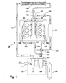
- FIG. 1 is a block diagram of an engine system that includes a turbocharger and an exhaust gas control valve in accordance with an exemplary embodiment of the invention
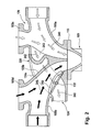
- FIG. 2 is fragmentary sectional view of a portion of the exhaust system and turbocharger shown in FIG. 1 in a normal operating mode;
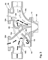
- FIG. 3 is a fragmentary sectional view of the exhaust system and turbocharger shown in FIG. 2 in an engine braking mode of operation;
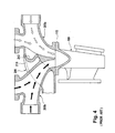
- FIG. 4 is a fragmentary sectional view of a portion of a prior art exhaust system and turbocharger in a normal operating mode
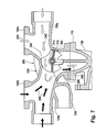
- FIG. 5 is a fragmentary sectional view of an alternate exemplary embodiment exhaust system and turbocharger in accordance with the invention shown in a normal mode of operation;
- FIG. 6 is a perspective view of a portion of the exhaust system shown in FIG. 5 ;
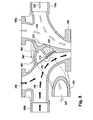
- FIG. 7 is a fragmentary sectional view of the exhaust system shown in FIG. 5 in an engine braking mode of operation
- FIG. 8 is a fragmentary sectional view of a further alternate exemplary embodiment exhaust system and turbocharger in accordance with the invention shown in a normal mode of operation;
- FIG. 9 is an exploded perspective view of a portion of the exhaust system shown in FIG. 8 ;
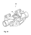
- FIG. 10 is a reduced perspective view of the portion of the exhaust system shown in FIG. 9 as assembled.
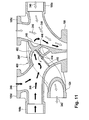
- FIG. 11 is a fragmentary sectional view of the exhaust system shown in FIG. 8 in an engine braking mode of operation.
- the engine 100 has a block 101 that includes a plurality of cylinders.
- the cylinders in the block 101 are fluidly connected to an intake system 103 and to an exhaust system 105.
- the exhaust system includes a first pipe 105a from cylinders 1, 2 and 3 of one bank of cylinders and a second pipe 105b from cylinders 4, 5 and 6 of an opposite bank of cylinders.
- a turbocharger 107 includes a turbine 109.
- the turbine 109 shown has a single turbine inlet port 113 connected to the exhaust system 105.
- the turbocharger 107 may additionally include a compressor 111 connected to the intake system 103 through an inlet air passage 115.
- air may enter the compressor 111 through an air inlet 117.
- Compressed air may exit the compressor 111 through the inlet air passage 115, and pass through an optional charge air cooler 119 and an optional inlet throttle 121 before entering an intake manifold 122 of the intake system 103.
- Exhaust gas from the exhaust system 105 may be routed through an exhaust gas recirculation (EGR) conduit 124 to an exhaust gas recirculation (EGR) cooler 123 and pass through an EGR valve 125 before meeting and mixing with air from the inlet throttle 121 at a junction 127.
- EGR exhaust gas recirculation
- EGR exhaust gas recirculation
- the inlet port 113 of the turbine 109 may be connected to the exhaust pipes 105a, 105b in a manner that forms a distribution manifold 129. Exhaust gas passing through the turbine 109 may exit the engine system 100 through a tailpipe 135.
- exhaust gas flows through the first pipe 105a, through the conduit 124, through the EGR cooler 123, through the EGR valve 125 and into the junction 127 where it mixes with air from the inlet throttle 121.
- An amount of exhaust gas being re-circulated through the EGR valve 125 may depend on an opening percentage of the EGR valve 125.
- the conduit 124 is also connected to the second pipe 105b.
- a relatively short cross pipe 124a of the conduit 124 is arranged between the pipes 105a and 105b.
- the cross pipe 124a facilitates exhaust gas flow in either direction depending on the operating mode.
- An engine brake valve 133 is positioned within the intersection of the conduit 124 and the second pipe 105b. During normal operation, the valve 133 closes the flow connection between the conduit 124 and the second pipe 105b.
- exhaust gas flows from the first pipe 105a to the inlet 113 of the turbine and some amount of exhaust gas flows from the first pipe 105a to the EGR cooler 123. Exhaust gas flowing within the second pipe 105b flows through the valve 133 and into the turbine inlet 113 and generally does not flow through the valve 133 into or from the conduit 124.
- valve 133 changes position and opens a flow path through the cross pipe 124a from the second pipe 105b to the first pipe 105a and closes the flow path from the second pipe 105b to the turbine inlet 113.
- the valve 133 can be configured to also close the flow path from the second pipe 105b to the EGR cooler 123 or alternately the EGR valve 125 can be closed to close this flow path.
- FIG. 4 A prior art arrangement of an exhaust manifold 200 and turbine 109 is shown in FIG. 4 .
- the exhaust manifold 200 includes a first exhaust pipe 205a receiving exhaust gas from cylinders 1, 2 and 3 and a second exhaust pipe 205b receiving exhaust gas from cylinders 4, 5 and 6 that are flow connected to the turbine inlet 113.
- An EGR conduit 210 branches off the pipe 205a and is located behind the pipe 205b but not flow connected to the pipe 205b. EGR flow is taken from the pipe 205a only and is controlled by an EGR valve (not shown) downstream and in flow communication with the EGR conduit 210.
- FIGS. 2 and 3 illustrate a modification of the arrangement shown in FIG.4 in order to configure the exhaust system as shown in FIG. 1 .
- a modified exhaust manifold 220 is provided.
- FIG. 2 shows the brake valve 133 in a first mode of operation.
- This mode generally corresponds to a normal operation (no engine braking) of the engine.
- a controlled amount of exhaust gas, the EGR exhaust gas 242 passes through an opening 243 in the first pipe 105a and into the cross pipe 124a (beneath the second pipe 105b) and through the EGR conduit 124 to the EGR cooler 123 (shown in FIG. 1 ).
- the EGR exhaust gas 242 is controlled by the EGR valve 125 (shown in FIG.
- the EGR valve 125 is controlled by the engine control unit or computer to limit emissions.
- a second exhaust gas portion 246 of exhaust gas flows through a branch pipe 105d from no. 4 cylinder (see Figure 1 ) and through the second pipe 105b from the nos. 5 and 6 cylinders, to the turbine inlet 113.
- the valve 133 closes an opening 250 formed or cut though a wall of the second pipe 105b that would otherwise open the second pipe 105b to the cross pipe 124a.
- FIG. 3 shows the brake valve 133 in a second mode of operation.
- This mode corresponds to an engine braking mode of operation.
- FIG. 3 demonstrates one aspect of operation, that is, the re-routing of exhaust gas to increase the speed of the turbine and thus increase the amount of compressed air into the engine.
- one or more exhaust valves of the engine can be opened, as described in U.S. Patents 6,594,996 ; 6,148,793 ; 6,779,506 ; 6,772,742 or 6,705,282 , herein incorporated by reference, to maximizing braking horsepower developed by the engine.
- the valve 133 has been rotated to be positioned into the second pipe 105b to block the EGR exhaust gas 242 from entering the turbine inlet 113 directly from the second pipe 105b.
- the EGR valve 125 can be closed or otherwise controlled to block or limit the EGR flow 246 through the conduit 124 to the cooler 123.
- FIG. 5 illustrates a further embodiment of the invention wherein a modified exhaust manifold 300 and turbine 109 shown in FIG. 4 has been modified with a central valve 302.
- FIG. 5 shows a first mode of operation. This mode generally corresponds to a normal operation (no engine braking) of the engine.
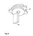
- the valve 302 includes a base 304 with a valve seat 306 (shown in Figure 6 ).
- a rotatable butterfly-type valve element 310 is mounted on an axle or spindle 314.
- the valve allows the first exhaust gas portion 240 from the branch pipe 105c and the first pipe 105a to flow into the turbine inlet.
- the EGR exhaust gas 242 flows through the opening 243 in the wall of the first pipe 105a, through the EGR conduit 124 behind or beneath the second pipe 105b, and to the EGR cooler and EGR valve as shown in FIG. 1 . There is no opening 250 in the embodiment shown in FIGS. 5 and 7 .
- the second exhaust gas portion 246 from the branch pipe 105d and the second pipe 105b flows into the turbine inlet 113.
- FIG. 7 shows a second mode of operation. This mode corresponds to an engine braking mode of operation.
- FIG. 7 demonstrates one aspect of operation, that is, the re-routing of exhaust gas to increase the speed of the turbine and thus increase the amount of compressed air into the engine.
- one or more exhaust valves of the engine can be opened, as described in U.S. Patents 6,594,996 ; 6,148,793 ; 6,779,506 ; 6,772,742 or 6,705,282 , herein incorporated by reference, to maximizing braking horsepower developed by the engine.
- the valve element 310 has been pivoted about the axle or spindle 314 by an external actuator (not shown) to be in a position wherein the first exhaust gas portion 240 from the branch pipe 105c and the first pipe 105a cannot enter the turbine inlet 113 directly but must pass over the valve element 310 to enter the second pipe 105b to flow with the second exhaust gas portion 246 into the inlet 113.
- the EGR valve 125 (shown in FIG. 1 ) can be closed or otherwise controlled to block or limit the EGR exhaust gas 242 though the opening 243 and the EGR conduit 124 to the cooler 123 (shown in FIG. 1 ).
- FIG. 8 illustrates a still further embodiment of the invention wherein a modified exhaust manifold 400 and turbine 109 shown in FIG. 4 has been modified with a central valve 402.
- FIG. 8 shows a first mode of operation. This mode generally corresponds to a normal operation (no engine braking) of the engine.
- the valve 402 includes a cover 404 with a bushing 406 that journals and seals a spindle 414 (shown in Figure 9 ).
- a rotatable butterfly-type valve element 410 is mounted on the spindle 414.
- the valve 402 allows the first exhaust gas portion 240 from the branch pipe 105c and the first pipe 105a to flow into the turbine inlet.
- the EGR exhaust gas 242 flows through the opening 243 in the wall of the first pipe 105a, through the EGR conduit 124 behind or beneath the second pipe 105b, and to the EGR cooler and EGR valve as shown in FIG. 1 .
- the second exhaust gas portion 246 from the branch pipe 105d and the second pipe 105b flows into the turbine inlet 113.
- a flat stop surface 426 of the manifold 400 is provided to support the butterfly element 410.
- FIG. 11 shows a second mode of operation. This mode corresponds to an engine braking mode of operation.
- FIG. 11 demonstrates one aspect of operation, that is, the re-routing of exhaust gas to increase the speed of the turbine and thus increase the amount of compressed air into the engine.
- one or more exhaust valves of the engine can be opened, as described in U.S. Patents 6,594,996 ; 6,148,793 ; 6,779,506 ; 6,772,742 or 6,705,282 , herein incorporated by reference, to maximizing braking horsepower developed by the engine.
- the valve element 410 has been pivoted about the spindle 414 by an external actuator (not shown) to be in a position wherein the second exhaust gas portion 246 from the branch pipes 105b and 105d cannot enter the turbine inlet 113 directly but must pass over the valve element 410 and through the opening 243 to enter the first pipe 105a to flow with the first exhaust gas portion 240 into the inlet 113.
- the EGR valve 125 (shown in FIG. 1 ) can be closed or otherwise controlled to block or limit the EGR exhaust gas 242 though the opening 243 and the EGR conduit 124 to the cooler 123 (shown in FIG. 1 ).
- a flat stop surface 446 of the manifold 400 is provided to support the butterfly element 410.
Landscapes
- Engineering & Computer Science (AREA)
- Chemical & Material Sciences (AREA)
- Combustion & Propulsion (AREA)
- Mechanical Engineering (AREA)
- General Engineering & Computer Science (AREA)
- Exhaust-Gas Circulating Devices (AREA)
- Control Of Throttle Valves Provided In The Intake System Or In The Exhaust System (AREA)
- Output Control And Ontrol Of Special Type Engine (AREA)
Abstract
An engine braking system includes a turbocharger having a turbine and a compressor. An exhaust manifold includes a first pipe for channeling a first portion of the engine exhaust and a second pipe for channeling a second portion of the engine exhaust. The first and second pipes are connected to an inlet of the turbine. A cross pipe, as part of an exhaust gas recirculation (EGR) conduit, is open between the first and second pipes and at one end to the remaining portion of the EGR conduit. A valve can be arranged within the cross pipe and ca be operable in a first mode of operation to block flow between the first and second pipes and allow flow between the first pipe and the remaining portion of the EGR conduit and to allow flow between the first and second pipes and the inlet of the turbine. The valve is operable in a second mode of operation to allow flow between the first and second pipes, and to reduce or block flow between the second pipe and the turbine inlet.
Description
- This application claims the priority of Provisional Patent Application No.
61/088,634, filed on 13 August 2008 - This invention relates to internal combustion engines, including but not limited to control and operation of a turbocharger, EGR system and engine braking for an internal combustion engine.
- Adequate and reliable braking for vehicles, particularly large tractor-trailer vehicles is desirable. While drum or disc wheel brakes are capable of absorbing a large amount of energy over a short period of time, the absorbed energy is transformed into heat in the braking mechanism.
- Multi-cylinder internal combustion engines, particularly diesel engines for large tractor-trailer trucks, may include an exhaust-gas turbocharger. The turbocharger includes a turbine that drives a compressor via a shaft, which generates an increased intake air pressure in the intake duct during normal operation.
- Braking systems are known which include exhaust brakes which inhibit the flow of exhaust gases through the exhaust system, and compression release systems wherein the energy required to compress the intake air during the compression stroke of the engine is dissipated by exhausting the compressed air through the exhaust system.
- In order to achieve a high engine-braking action a brake valve in the exhaust line may be closed during braking, and excess pressure is built up in the exhaust line upstream of the brake valve. The built-up exhaust gas flows at high velocity into the turbine and acts on the turbine rotor, whereupon the driven compressor increases pressure in the air intake duct. The cylinders are subjected to an increased charging pressure. In the exhaust system, an excess pressure develops between the cylinder outlet and the brake valve and counteracts the discharge of the air compressed in the cylinder into the exhaust tract via the exhaust valves. During braking, the piston performs compression work against the high excess pressure in the exhaust tract, with the result that a strong braking action is achieved.
- Another method disclosed in
U.S. Patent No. 4,395,884 includes employing a turbocharged engine equipped with a double entry turbine and a compression release engine retarder in combination with a diverter valve. During engine braking, the diverter valve directs the flow of air through one scroll of the divided volute of the turbine. When engine braking is employed, the turbine speed is maximized, and the inlet manifold pressure is also maximized, thereby maximizing braking horsepower developed by the engine. - Other methods employ a variable geometry turbocharger (VGT). When engine braking is commanded, the variable geometry turbocharger is "clamped down" which means the turbine vanes are closed and used to generate both high exhaust manifold pressure and high turbine speeds and high turbocharger speeds. Increasing the turbocharger speed in turn increases the engine airflow and available engine brake power. The method disclosed in
U.S. Patent No. 6,594,996 includes controlling the geometry of the turbocharger for engine braking as a function of engine speed and pressure (exhaust or intake, preferably exhaust).U.S. Patent 6,148,793 describes a brake control for an engine having a variable geometry turbocharger which is controllable to vary intake manifold pressure. The engine is operable in a braking mode using a turbocharger geometry actuator for varying turbocharger geometry, and using an exhaust valve actuator for opening an exhaust valve of the engine. - Other methods of using turbochargers for engine braking are disclosed in
U.S. Patent Nos. 6,223,534 and4,474,006 . - Controlled engine exhaust gas recirculation is a known technique for reducing oxides of nitrogen in products of combustion that are exhausted from an internal combustion engine to atmosphere. A typical EGR system comprises an EGR valve that is controlled in accordance with engine operating conditions to regulate the amount of engine exhaust gas that is re-circulated from the engine exhaust system to the air intake system so as to limit the combustion temperature and hence reduce the formation of oxides of nitrogen during combustion. Such a system is described for example in
U.S. Patent No. 7,363,761 . - The exemplary embodiments of the invention provide an engine braking system including a turbocharger having a turbine and a compressor. An exhaust manifold includes a first pipe for channeling a first portion of the engine exhaust and a second pipe for channeling a second portion of the engine exhaust. The first and second pipes are connected to an inlet of the turbine. A cross pipe, as part of an exhaust gas recirculation (EGR) conduit, is open between the first and second pipes and at one end to the remaining portion of the EGR conduit. A valve can be arranged within the cross pipe and is operable in a first mode of operation to block flow between the first and second pipes and allow flow between the first pipe and the remaining portion of the EGR conduit and to allow flow between the first and second pipes and the inlet of the turbine. The valve is operable in a second mode of operation to allow flow between the first and second pipes, and to block flow between the second pipe and the turbine inlet. Thus, a substantially reduced flow occurs between the second pipe and the turbine inlet and a substantially increased flow occurs between the first pipe and the turbine inlet. One example of the second mode of operation is that no flow occurs between the second pipe and the turbine inlet, no flow occurs through the remaining portion of the EGR conduit, the second portion of the exhaust gas flows through the cross pipe, and substantially the first and second portions of the total exhaust flow is channeled through the first pipe and into the turbine inlet.
- According to the exemplary embodiment, during operation in the second mode a control positions the valve and closes an EGR valve that is within the EGR conduit. In the first mode of operation, the EGR valve is controlled by the engine control module and software therein to reduce emissions.
- The turbine may comprise a variable geometry turbine and/or a divided volute turbine.
- According to the exemplary embodiment, the valve comprises a flapper valve rotatable between two positions corresponding to the first and second modes.
- The exemplary embodiment of the invention provides an exhaust and air intake system for an engine. The system includes a first exhaust pipe means for channeling a first portion of exhaust gas generated by the engine, and a second exhaust pipe means for channeling a second portion of the exhaust gas generated by the engine. An air intake system includes an air compressor, an air inlet to the air compressor, and a compressed air intake manifold. A turbine drives the air compressor; the turbine having a turbine inlet for flow-connecting the first and second exhaust pipe means. An exhaust gas recirculation (EGR) means selectively connects the first pipe means, the second pipe means and the air intake system and selectively delivers exhaust gas to the air intake system. The EGR system can also selectively channel exhaust gas flow, in a reverse direction, between the first and second pipe means. A valve means, in a first mode of operation, opens exhaust gas flow between the second pipe means and the turbine inlet and closes exhaust gas flow between the second pipe means and the exhaust gas recirculation means. Accordingly, an amount of exhaust gas from the first portion of exhaust gas flows through the first pipe means into the exhaust gas recirculation means and a remaining amount of the first portion of exhaust gas flows from the first pipe means to the turbine inlet. The second portion of exhaust gas flows through the second pipe means into the turbine inlet. The valve means, in a second mode of operation, closes exhaust gas flow between the second pipe means and the turbine inlet and opens exhaust gas flow between the second pipe means and the exhaust gas recirculation means.
- The valve means can include a flapper or butterfly plate valve located between the exhaust gas recirculation means and the second pipe means, and an EGR valve located in the exhaust gas recirculation means. In the second mode of operation, the EGR valve can be substantially closed or made more restrictive to flow, and in the first mode of operation the EGR valve is controlled to reduce engine emissions.
- Numerous other advantages and features of the present invention will be become readily apparent from the following detailed description of the invention and the embodiments thereof, from the claims and from the accompanying drawings.
-
FIG. 1 is a block diagram of an engine system that includes a turbocharger and an exhaust gas control valve in accordance with an exemplary embodiment of the invention; -
FIG. 2 is fragmentary sectional view of a portion of the exhaust system and turbocharger shown inFIG. 1 in a normal operating mode; -
FIG. 3 is a fragmentary sectional view of the exhaust system and turbocharger shown inFIG. 2 in an engine braking mode of operation; -
FIG. 4 is a fragmentary sectional view of a portion of a prior art exhaust system and turbocharger in a normal operating mode; -
FIG. 5 is a fragmentary sectional view of an alternate exemplary embodiment exhaust system and turbocharger in accordance with the invention shown in a normal mode of operation; -
FIG. 6 is a perspective view of a portion of the exhaust system shown inFIG. 5 ; -
FIG. 7 is a fragmentary sectional view of the exhaust system shown inFIG. 5 in an engine braking mode of operation -
FIG. 8 is a fragmentary sectional view of a further alternate exemplary embodiment exhaust system and turbocharger in accordance with the invention shown in a normal mode of operation; -
FIG. 9 is an exploded perspective view of a portion of the exhaust system shown inFIG. 8 ; -
FIG. 10 is a reduced perspective view of the portion of the exhaust system shown inFIG. 9 as assembled; and -
FIG. 11 is a fragmentary sectional view of the exhaust system shown inFIG. 8 in an engine braking mode of operation. - While this invention is susceptible of embodiment in many different forms, there are shown in the drawings, and will be described herein in detail, specific embodiments thereof with the understanding that the present disclosure is to be considered as an exemplification of the principles of the invention and is not intended to limit the invention to the specific embodiments illustrated.
- An
engine 100 is shown schematically inFIG. 1 . Theengine 100 has ablock 101 that includes a plurality of cylinders. The cylinders in theblock 101 are fluidly connected to anintake system 103 and to anexhaust system 105. The exhaust system includes afirst pipe 105a fromcylinders second pipe 105b fromcylinders turbocharger 107 includes aturbine 109. Theturbine 109 shown has a singleturbine inlet port 113 connected to theexhaust system 105. Theturbocharger 107 may additionally include acompressor 111 connected to theintake system 103 through aninlet air passage 115. - During operation of the
engine 100, air may enter thecompressor 111 through anair inlet 117. Compressed air may exit thecompressor 111 through theinlet air passage 115, and pass through an optionalcharge air cooler 119 and anoptional inlet throttle 121 before entering anintake manifold 122 of theintake system 103. - Exhaust gas from the
exhaust system 105 may be routed through an exhaust gas recirculation (EGR)conduit 124 to an exhaust gas recirculation (EGR) cooler 123 and pass through anEGR valve 125 before meeting and mixing with air from theinlet throttle 121 at ajunction 127. - The
inlet port 113 of theturbine 109 may be connected to theexhaust pipes distribution manifold 129. Exhaust gas passing through theturbine 109 may exit theengine system 100 through atailpipe 135. - At times when the
EGR valve 125 is at least partially open, exhaust gas flows through thefirst pipe 105a, through theconduit 124, through theEGR cooler 123, through theEGR valve 125 and into thejunction 127 where it mixes with air from theinlet throttle 121. An amount of exhaust gas being re-circulated through theEGR valve 125 may depend on an opening percentage of theEGR valve 125. - The
conduit 124 is also connected to thesecond pipe 105b. A relativelyshort cross pipe 124a of theconduit 124 is arranged between thepipes cross pipe 124a facilitates exhaust gas flow in either direction depending on the operating mode. Anengine brake valve 133 is positioned within the intersection of theconduit 124 and thesecond pipe 105b. During normal operation, thevalve 133 closes the flow connection between theconduit 124 and thesecond pipe 105b. During normal operation, exhaust gas flows from thefirst pipe 105a to theinlet 113 of the turbine and some amount of exhaust gas flows from thefirst pipe 105a to theEGR cooler 123. Exhaust gas flowing within thesecond pipe 105b flows through thevalve 133 and into theturbine inlet 113 and generally does not flow through thevalve 133 into or from theconduit 124. - During engine braking however, the
valve 133 changes position and opens a flow path through thecross pipe 124a from thesecond pipe 105b to thefirst pipe 105a and closes the flow path from thesecond pipe 105b to theturbine inlet 113. Thevalve 133 can be configured to also close the flow path from thesecond pipe 105b to the EGR cooler 123 or alternately theEGR valve 125 can be closed to close this flow path. - Because the exhaust gas from both the bank of
cylinders cylinders U.S. Patent Nos. 6,594,996 ;6,223,534 ;6,148,793 ;4,474,006 and4,395,884 ; all herein incorporated by reference. - A prior art arrangement of an
exhaust manifold 200 andturbine 109 is shown inFIG. 4 . Theexhaust manifold 200 includes afirst exhaust pipe 205a receiving exhaust gas fromcylinders second exhaust pipe 205b receiving exhaust gas fromcylinders turbine inlet 113. AnEGR conduit 210 branches off thepipe 205a and is located behind thepipe 205b but not flow connected to thepipe 205b. EGR flow is taken from thepipe 205a only and is controlled by an EGR valve (not shown) downstream and in flow communication with theEGR conduit 210. -
FIGS. 2 and3 illustrate a modification of the arrangement shown inFIG.4 in order to configure the exhaust system as shown inFIG. 1 . A modifiedexhaust manifold 220 is provided. -
FIG. 2 shows thebrake valve 133 in a first mode of operation. This mode generally corresponds to a normal operation (no engine braking) of the engine. A firstexhaust gas portion 240 flowing through abranch pipe 105c from no. 1 cylinder (seeFigure 1 ) and through thefirst pipe 105a from nos. 2 and 3 cylinders, enters the turbine inlet. A controlled amount of exhaust gas, theEGR exhaust gas 242, passes through anopening 243 in thefirst pipe 105a and into thecross pipe 124a (beneath thesecond pipe 105b) and through theEGR conduit 124 to the EGR cooler 123 (shown inFIG. 1 ). TheEGR exhaust gas 242 is controlled by the EGR valve 125 (shown inFIG. 1 ) that is downstream of the cooler 123. TheEGR valve 125 is controlled by the engine control unit or computer to limit emissions. A secondexhaust gas portion 246 of exhaust gas flows through abranch pipe 105d from no. 4 cylinder (seeFigure 1 ) and through thesecond pipe 105b from the nos. 5 and 6 cylinders, to theturbine inlet 113. Thevalve 133 closes anopening 250 formed or cut though a wall of thesecond pipe 105b that would otherwise open thesecond pipe 105b to thecross pipe 124a. -
FIG. 3 shows thebrake valve 133 in a second mode of operation. This mode corresponds to an engine braking mode of operation. During engine braking,FIG. 3 demonstrates one aspect of operation, that is, the re-routing of exhaust gas to increase the speed of the turbine and thus increase the amount of compressed air into the engine. In addition to the operation described inFIG. 3 , one or more exhaust valves of the engine can be opened, as described inU.S. Patents 6,594,996 ;6,148,793 ;6,779,506 ;6,772,742 or6,705,282 , herein incorporated by reference, to maximizing braking horsepower developed by the engine. - The first
exhaust gas portion 240 flowing through thebranch pipe 105c from the no. 1 cylinder (seeFigure 1 ) and through thefirst pipe 105a from nos. 2 and 3 cylinders, enters theturbine inlet 113. Thevalve 133 has been rotated to be positioned into thesecond pipe 105b to block theEGR exhaust gas 242 from entering theturbine inlet 113 directly from thesecond pipe 105b. The secondexhaust gas portion 246 flowing through thebranch pipe 105d from no. 4 cylinder (seeFigure 1 ) and through thesecond pipe 105b from the nos. 5 and 6 cylinders, flows through theopening 250 in the wall of thesecond pipe 105b, and into thecross pipe 124a (beneath or behind thesecond pipe 105b) in a reverse direction compared to the flow through thecross pipe 124a in the first mode of operation. The secondexhaust gas portion 242 must join the firstexhaust gas portion 240 and flow though thefirst pipe 105a into theturbine inlet 113. During engine braking, theEGR valve 125 can be closed or otherwise controlled to block or limit theEGR flow 246 through theconduit 124 to the cooler 123. -
FIG. 5 illustrates a further embodiment of the invention wherein a modifiedexhaust manifold 300 andturbine 109 shown inFIG. 4 has been modified with acentral valve 302.FIG. 5 shows a first mode of operation. This mode generally corresponds to a normal operation (no engine braking) of the engine. Thevalve 302 includes a base 304 with a valve seat 306 (shown inFigure 6 ). A rotatable butterfly-type valve element 310 is mounted on an axle orspindle 314. In the first mode of operation shown inFIG. 5 , the valve allows the firstexhaust gas portion 240 from thebranch pipe 105c and thefirst pipe 105a to flow into the turbine inlet. TheEGR exhaust gas 242 flows through theopening 243 in the wall of thefirst pipe 105a, through theEGR conduit 124 behind or beneath thesecond pipe 105b, and to the EGR cooler and EGR valve as shown inFIG. 1 . There is noopening 250 in the embodiment shown inFIGS. 5 and7 . The secondexhaust gas portion 246 from thebranch pipe 105d and thesecond pipe 105b flows into theturbine inlet 113. -
FIG. 7 shows a second mode of operation. This mode corresponds to an engine braking mode of operation. During engine braking,FIG. 7 demonstrates one aspect of operation, that is, the re-routing of exhaust gas to increase the speed of the turbine and thus increase the amount of compressed air into the engine. In addition to the operation described inFIG. 7 , one or more exhaust valves of the engine can be opened, as described inU.S. Patents 6,594,996 ;6,148,793 ;6,779,506 ;6,772,742 or6,705,282 , herein incorporated by reference, to maximizing braking horsepower developed by the engine. - The
valve element 310 has been pivoted about the axle orspindle 314 by an external actuator (not shown) to be in a position wherein the firstexhaust gas portion 240 from thebranch pipe 105c and thefirst pipe 105a cannot enter theturbine inlet 113 directly but must pass over thevalve element 310 to enter thesecond pipe 105b to flow with the secondexhaust gas portion 246 into theinlet 113. The EGR valve 125 (shown inFIG. 1 ) can be closed or otherwise controlled to block or limit theEGR exhaust gas 242 though theopening 243 and theEGR conduit 124 to the cooler 123 (shown inFIG. 1 ). -
FIG. 8 illustrates a still further embodiment of the invention wherein a modifiedexhaust manifold 400 andturbine 109 shown inFIG. 4 has been modified with acentral valve 402.FIG. 8 shows a first mode of operation. This mode generally corresponds to a normal operation (no engine braking) of the engine. Thevalve 402 includes acover 404 with abushing 406 that journals and seals a spindle 414 (shown inFigure 9 ). A rotatable butterfly-type valve element 410 is mounted on thespindle 414. - In the first mode of operation shown in
FIG. 8 , thevalve 402 allows the firstexhaust gas portion 240 from thebranch pipe 105c and thefirst pipe 105a to flow into the turbine inlet. TheEGR exhaust gas 242 flows through theopening 243 in the wall of thefirst pipe 105a, through theEGR conduit 124 behind or beneath thesecond pipe 105b, and to the EGR cooler and EGR valve as shown inFIG. 1 . There is noopening 250 in the embodiment shown inFIGS. 8 and11 . The secondexhaust gas portion 246 from thebranch pipe 105d and thesecond pipe 105b flows into theturbine inlet 113. - A
flat stop surface 426 of the manifold 400 is provided to support thebutterfly element 410. -
FIG. 11 shows a second mode of operation. This mode corresponds to an engine braking mode of operation. During engine braking,FIG. 11 demonstrates one aspect of operation, that is, the re-routing of exhaust gas to increase the speed of the turbine and thus increase the amount of compressed air into the engine. In addition to the operation described inFIG. 11 , one or more exhaust valves of the engine can be opened, as described inU.S. Patents 6,594,996 ;6,148,793 ;6,779,506 ;6,772,742 or6,705,282 , herein incorporated by reference, to maximizing braking horsepower developed by the engine. - The
valve element 410 has been pivoted about thespindle 414 by an external actuator (not shown) to be in a position wherein the secondexhaust gas portion 246 from thebranch pipes turbine inlet 113 directly but must pass over thevalve element 410 and through theopening 243 to enter thefirst pipe 105a to flow with the firstexhaust gas portion 240 into theinlet 113. The EGR valve 125 (shown inFIG. 1 ) can be closed or otherwise controlled to block or limit theEGR exhaust gas 242 though theopening 243 and theEGR conduit 124 to the cooler 123 (shown inFIG. 1 ). - A
flat stop surface 446 of the manifold 400 is provided to support thebutterfly element 410. - From the foregoing, it will be observed that numerous variations and modifications may be effected without departing from the spirit and scope of the invention. It is to be understood that no limitation with respect to the specific apparatus illustrated herein is intended or should be inferred.
Claims (15)
- An engine braking system, comprising:a turbocharger having a turbine and a compressor;an exhaust manifold having a first pipe for channeling a first portion of the engine exhaust and a second pipe for channeling a second portion of the engine exhaust;said first and second pipes flow-connected to an inlet of the turbine;a cross pipe open between the first and second pipes and at one end to an exhaust gas recirculation (EGR) conduit;a valve arranged within the cross pipe and operable in a first mode to block flow between the first and second pipes and allow flow between the first pipe and the EGR conduit and allow flow between the second pipe and the inlet of the turbine, and operable in a second mode to allow flow between the first and second pipes, and block flow between the second pipe and the turbine inlet.
- The engine braking system according to claim 1, comprising a control and an EGR valve, and for operation in the second mode the control positions the valve in the second mode and closes the EGR valve.
- The engine braking system according to claim 1, wherein the turbine comprises a variable vane geometry turbine.
- The engine braking system according to claim 1, wherein the turbine comprises a divided volute turbine.
- The engine braking system according to claim 1, wherein the valve comprises a flapper valve rotatable between two positions corresponding to the first and second modes.
- An exhaust and air intake system for an engine, comprising:a first exhaust pipe channeling a first portion of exhaust gas generated by the engine, having a first outlet and a second exhaust pipe channeling a second portion of the exhaust gas generated by the engine, having a second outlet;an air intake system including an air compressor, an air inlet to the air compressor, and a compressed air intake manifold;a turbine driving the air compressor, the turbine having an inlet for connecting the first and second outlets of the first and second pipes respectively;an exhaust gas recirculation conduit connected between the first pipe and the second pipe and the air intake system;a valve system arranged in a first mode of operation, to open the first pipe to the exhaust gas recirculation conduit in order to deliver an amount of exhaust gas into the compressed air intake manifold, and in a second mode of operation, to close exhaust gas flow from the second pipe to the second outlet and direct the second portion of exhaust gas from the second pipe through the exhaust gas recirculation conduit, through the first pipe, through the first outlet, and into the turbine inlet.
- The exhaust and air intake system according to claim 6, wherein the valve system includes an EGR valve located in the exhaust gas recirculation conduit, wherein in the second mode of operation, the EGR valve is substantially closed, and in the first mode of operation the EGR valve is controlled to reduce engine emissions.
- The exhaust and air intake system according to claim 6, wherein the turbine comprises a variable vane geometry turbine.
- The exhaust and air intake system according to claim 6, wherein the turbine comprises a divided volute turbine.
- The exhaust and air intake system according to claim 6, wherein the valve comprises a flapper valve rotatable between two positions corresponding to the first and second modes.
- An exhaust and air intake system for an engine, comprising:a first exhaust pipe means for channeling a first portion of exhaust gas generated by the engine, and a second exhaust pipe means for channeling a second portion of the exhaust gas generated by the engine;an air intake system including an air compressor, an air inlet to the air compressor, and a compressed air intake manifold;a turbine driving the air compressor, the turbine having a turbine inlet for flow-connecting the first and second exhaust pipe means;an exhaust gas recirculation means for selectively connecting the first pipe means, the second pipe means and the air intake system and for selectively delivering exhaust gas to the air intake system or channeling exhaust gas flow between the first and second pipe means;a valve means for, in a first mode of operation, opening exhaust gas flow between the second pipe means and the turbine inlet and for closing exhaust gas flow between the second pipe means and the exhaust gas recirculation means, such that an amount of exhaust gas from the first portion of exhaust gas flows through the first pipe means into the exhaust gas recirculation means and a remaining amount of the first portion of exhaust gas flows from the first pipe means to the turbine inlet, and the second portion of exhaust gas flows through the second pipe means into the turbine inlet, and for, in a second mode of operation, closing exhaust gas flow between the second pipe means and the turbine inlet and opening exhaust gas flow between the second pipe means and the exhaust gas recirculation means.
- The exhaust and air intake system according to claim 11, wherein the valve means includes a flapper valve located between the exhaust gas recirculation means and the second pipe means, and an EGR valve located in the exhaust gas recirculation means, wherein in the second mode of operation, the EGR valve is substantially closed, and in the first mode of operation the EGR valve is controlled to reduce engine emissions.
- The exhaust and air intake system according to claim 11, wherein the turbine comprises a variable geometry turbine.
- The exhaust and air intake system according to claim 11, wherein the turbine comprises a divided volute turbine.
- The exhaust and air intake system according to claim 11, wherein the valve means comprises a flapper valve rotatable between two positions corresponding to the first and second modes.
Priority Applications (1)
| Application Number | Priority Date | Filing Date | Title |
|---|---|---|---|
| EP09010505A EP2295769A1 (en) | 2009-08-14 | 2009-08-14 | Exhaust system for engine braking |
Applications Claiming Priority (1)
| Application Number | Priority Date | Filing Date | Title |
|---|---|---|---|
| EP09010505A EP2295769A1 (en) | 2009-08-14 | 2009-08-14 | Exhaust system for engine braking |
Publications (1)
| Publication Number | Publication Date |
|---|---|
| EP2295769A1 true EP2295769A1 (en) | 2011-03-16 |
Family
ID=41343467
Family Applications (1)
| Application Number | Title | Priority Date | Filing Date |
|---|---|---|---|
| EP09010505A Withdrawn EP2295769A1 (en) | 2009-08-14 | 2009-08-14 | Exhaust system for engine braking |
Country Status (1)
| Country | Link |
|---|---|
| EP (1) | EP2295769A1 (en) |
Cited By (21)
| Publication number | Priority date | Publication date | Assignee | Title |
|---|---|---|---|---|
| DE102011118899A1 (en) * | 2011-11-18 | 2013-05-23 | Daimler Ag | Exhaust gas tract for use in six-cylinder in-line engine of motor vehicle, has control element insertable into tract unit through lockable mounting opening such that control element is pivotally mounted on lockable mounting opening |
| KR20130113098A (en) * | 2012-04-05 | 2013-10-15 | 두산인프라코어 주식회사 | Exhaust gas recirculation of engine |
| WO2014019667A1 (en) * | 2012-08-01 | 2014-02-06 | Daimler Ag | Method for treating exhaust gas and arrangement of an exhaust gas system on an internal combustion engine |
| EP2749757A1 (en) * | 2012-12-28 | 2014-07-02 | FPT Industrial S.p.A. | Method and apparatus for controlling a twin scroll turbocharger with variable geometry depending on the exhaust gas recirculation |
| FR3001770A1 (en) * | 2013-02-07 | 2014-08-08 | Valeo Sys Controle Moteur Sas | ENGINE EXHAUST GAS ADMISSION AND RECIRCULATION GAS SUPPLY SYSTEM AND METHOD OF CONTROLLING THE SAME |
| WO2014127889A1 (en) * | 2013-02-22 | 2014-08-28 | Daimler Ag | Exhaust gas system for an internal combustion engine |
| EP2803838A1 (en) * | 2013-05-15 | 2014-11-19 | Bayerische Motoren Werke Aktiengesellschaft | Exhaust gas turbocharger assembly |
| EP2476886A4 (en) * | 2009-09-08 | 2015-06-03 | Toyota Jidoshokki Kk | Internal combustion engine with supercharger |
| DE102013020448A1 (en) * | 2013-12-07 | 2015-06-11 | Daimler Ag | Method for operating a motor vehicle |
| CN104975925A (en) * | 2014-04-09 | 2015-10-14 | 曼卡车和巴士股份公司 | Exhaust manifold for an internal combustion engine, particularly in motor vehicles |
| WO2016001751A1 (en) * | 2014-07-02 | 2016-01-07 | Kangyue Technology Co., Ltd. | Quad layer passage variable geometry turbine for turbochargers in exhaust gas recirculation engines |
| US20160047326A1 (en) * | 2014-08-12 | 2016-02-18 | Cummins, Inc. | Systems and Methods for Aftertreatment Regeneration with Dedicated EGR |
| FR3027368A1 (en) * | 2014-10-17 | 2016-04-22 | Valeo Systemes De Controle Moteur | EXHAUST GAS CIRCULATION VALVE OF AN ENGINE, IN PARTICULAR FOR A MOTOR VEHICLE |
| EP3048285A1 (en) * | 2015-01-20 | 2016-07-27 | KNORR-BREMSE Systeme für Nutzfahrzeuge GmbH | Braking Flap and Exhaust Gas System |
| WO2016134876A1 (en) * | 2015-02-27 | 2016-09-01 | Volkswagen Aktiengesellschaft | Arrangement for an internal combustion engine having a plurality of cylinders and exhaust turbocharger, exhaust gas pressure transformer having a mixing tube and a wastegate, and method for operating and configuring such an arrangement |
| JP2017145769A (en) * | 2016-02-18 | 2017-08-24 | 日野自動車株式会社 | Supercharged engine and method for operating the same |
| CN107091163A (en) * | 2016-02-18 | 2017-08-25 | 通用汽车环球科技运作有限责任公司 | Special exhaust gas recirculation control systems and method |
| WO2018127368A1 (en) * | 2017-01-09 | 2018-07-12 | Bayerische Motoren Werke Aktiengesellschaft | Exhaust manifold for an internal combustion engine |
| CN111927656A (en) * | 2020-09-25 | 2020-11-13 | 山东信德玛珂增压器股份有限公司 | Exhaust gas recirculation system with asymmetric flow |
| WO2021191338A1 (en) * | 2020-03-27 | 2021-09-30 | Cummins Ltd | Internal combustion engine system with exhaust gas flow control |
| EP4080036A1 (en) * | 2021-04-21 | 2022-10-26 | Volvo Truck Corporation | Internal combustion engine system |
Citations (14)
| Publication number | Priority date | Publication date | Assignee | Title |
|---|---|---|---|---|
| US4395884A (en) | 1981-02-26 | 1983-08-02 | The Jacobs Manufacturing Company | Method and apparatus for improved engine braking and operation |
| US4474006A (en) | 1982-09-30 | 1984-10-02 | The Jacobs Mfg. Company | Method and apparatus for improved compression release engine retarding in a turbocharged internal combustion engine |
| US6148793A (en) | 1994-07-29 | 2000-11-21 | Caterpillar Inc. | Engine compression braking apparatus utilizing a variable geometry turbocharger |
| US6223534B1 (en) | 1998-08-13 | 2001-05-01 | Daimlerchrysler Ag | Engine-braking arrangement for an internal combustion engine with an exhaust-gas turbocharger |
| US6594996B2 (en) | 2001-05-22 | 2003-07-22 | Diesel Engine Retarders, Inc | Method and system for engine braking in an internal combustion engine with exhaust pressure regulation and turbocharger control |
| US6705282B2 (en) | 2002-03-01 | 2004-03-16 | International Engine Intellectual Property Company, Llc | Method and apparatus to provide engine compression braking |
| US6772742B2 (en) | 2002-03-01 | 2004-08-10 | International Engine Intellectual Property Company, Llc | Method and apparatus for flexibly regulating internal combustion engine valve flow |
| US6779506B1 (en) | 2003-09-23 | 2004-08-24 | International Engine Intellectual Property Company, Llc | Engine brake control pressure strategy |
| WO2005061870A1 (en) * | 2003-12-11 | 2005-07-07 | Daimlerchrysler Ag | Combustion engine having an exhaust gas turbocharger and exhaust gas recirculation |
| DE102006022181A1 (en) * | 2006-05-12 | 2007-11-15 | Daimlerchrysler Ag | Internal combustion engine with exhaust turbocharger and exhaust feedback has multi-action slide valve that controls transfer devices between common rails and in exhaust gas lines depending on its control position |
| US20080000229A1 (en) * | 2004-08-18 | 2008-01-03 | Alfred Kuspert | Internal combustion engine having an exhaust gas turbocharge and an exhaust gas recirculation system |
| US7363761B1 (en) | 2006-10-31 | 2008-04-29 | International Engine Intellectual Property Company, Llc | Exhaust gas throttle for divided turbine housing turbocharger |
| DE102007036937A1 (en) * | 2007-08-04 | 2009-02-05 | Daimler Ag | Exhaust gas turbocharger for a reciprocating internal combustion engine |
| US20090120087A1 (en) * | 2006-04-28 | 2009-05-14 | Siegfried Sumser | Exhaust gas turbocharger in an internal combustion engine |
-
2009
- 2009-08-14 EP EP09010505A patent/EP2295769A1/en not_active Withdrawn
Patent Citations (14)
| Publication number | Priority date | Publication date | Assignee | Title |
|---|---|---|---|---|
| US4395884A (en) | 1981-02-26 | 1983-08-02 | The Jacobs Manufacturing Company | Method and apparatus for improved engine braking and operation |
| US4474006A (en) | 1982-09-30 | 1984-10-02 | The Jacobs Mfg. Company | Method and apparatus for improved compression release engine retarding in a turbocharged internal combustion engine |
| US6148793A (en) | 1994-07-29 | 2000-11-21 | Caterpillar Inc. | Engine compression braking apparatus utilizing a variable geometry turbocharger |
| US6223534B1 (en) | 1998-08-13 | 2001-05-01 | Daimlerchrysler Ag | Engine-braking arrangement for an internal combustion engine with an exhaust-gas turbocharger |
| US6594996B2 (en) | 2001-05-22 | 2003-07-22 | Diesel Engine Retarders, Inc | Method and system for engine braking in an internal combustion engine with exhaust pressure regulation and turbocharger control |
| US6772742B2 (en) | 2002-03-01 | 2004-08-10 | International Engine Intellectual Property Company, Llc | Method and apparatus for flexibly regulating internal combustion engine valve flow |
| US6705282B2 (en) | 2002-03-01 | 2004-03-16 | International Engine Intellectual Property Company, Llc | Method and apparatus to provide engine compression braking |
| US6779506B1 (en) | 2003-09-23 | 2004-08-24 | International Engine Intellectual Property Company, Llc | Engine brake control pressure strategy |
| WO2005061870A1 (en) * | 2003-12-11 | 2005-07-07 | Daimlerchrysler Ag | Combustion engine having an exhaust gas turbocharger and exhaust gas recirculation |
| US20080000229A1 (en) * | 2004-08-18 | 2008-01-03 | Alfred Kuspert | Internal combustion engine having an exhaust gas turbocharge and an exhaust gas recirculation system |
| US20090120087A1 (en) * | 2006-04-28 | 2009-05-14 | Siegfried Sumser | Exhaust gas turbocharger in an internal combustion engine |
| DE102006022181A1 (en) * | 2006-05-12 | 2007-11-15 | Daimlerchrysler Ag | Internal combustion engine with exhaust turbocharger and exhaust feedback has multi-action slide valve that controls transfer devices between common rails and in exhaust gas lines depending on its control position |
| US7363761B1 (en) | 2006-10-31 | 2008-04-29 | International Engine Intellectual Property Company, Llc | Exhaust gas throttle for divided turbine housing turbocharger |
| DE102007036937A1 (en) * | 2007-08-04 | 2009-02-05 | Daimler Ag | Exhaust gas turbocharger for a reciprocating internal combustion engine |
Cited By (45)
| Publication number | Priority date | Publication date | Assignee | Title |
|---|---|---|---|---|
| US9239021B2 (en) | 2009-09-08 | 2016-01-19 | Kabushiki Kaisha Toyota Jidoshokki | Internal combustion engine with supercharger |
| EP2476886A4 (en) * | 2009-09-08 | 2015-06-03 | Toyota Jidoshokki Kk | Internal combustion engine with supercharger |
| DE102011118899A1 (en) * | 2011-11-18 | 2013-05-23 | Daimler Ag | Exhaust gas tract for use in six-cylinder in-line engine of motor vehicle, has control element insertable into tract unit through lockable mounting opening such that control element is pivotally mounted on lockable mounting opening |
| US9506427B2 (en) | 2012-04-05 | 2016-11-29 | Doosan Infracore Co., Ltd. | System for recirculating engine exhaust gas |
| KR20130113098A (en) * | 2012-04-05 | 2013-10-15 | 두산인프라코어 주식회사 | Exhaust gas recirculation of engine |
| EP2835524A4 (en) * | 2012-04-05 | 2016-04-13 | Doosan Infracore Co Ltd | System for recirculating engine exhaust gas |
| CN104204493A (en) * | 2012-04-05 | 2014-12-10 | 斗山英维高株式会社 | System for recirculating engine exhaust gas |
| WO2014019667A1 (en) * | 2012-08-01 | 2014-02-06 | Daimler Ag | Method for treating exhaust gas and arrangement of an exhaust gas system on an internal combustion engine |
| US9388720B2 (en) | 2012-08-01 | 2016-07-12 | Daimler Ag | Method for treating exhaust gas and arrangement of an exhaust gas system on an internal combustion engine |
| EP2749757A1 (en) * | 2012-12-28 | 2014-07-02 | FPT Industrial S.p.A. | Method and apparatus for controlling a twin scroll turbocharger with variable geometry depending on the exhaust gas recirculation |
| WO2014102236A1 (en) * | 2012-12-28 | 2014-07-03 | Fpt Industrial S.P.A. | Method and apparatus for controlling a twin scroll turbocharger with variable geometry depending on the exhaust gas recirculation |
| FR3001770A1 (en) * | 2013-02-07 | 2014-08-08 | Valeo Sys Controle Moteur Sas | ENGINE EXHAUST GAS ADMISSION AND RECIRCULATION GAS SUPPLY SYSTEM AND METHOD OF CONTROLLING THE SAME |
| CN105102802A (en) * | 2013-02-07 | 2015-11-25 | 法雷奥电机控制系统公司 | System for supercharging the intake gases and for recirculating the exhaust gases of engine and associated control method |
| WO2014122389A1 (en) * | 2013-02-07 | 2014-08-14 | Valeo Systemes De Controle Moteur | System for supercharging the intake gases and for recirculating the exhaust gases of an engine and associated control method |
| US9784221B2 (en) | 2013-02-22 | 2017-10-10 | Daimler Ag | Exhaust gas flow control system for an internal combustion engine |
| CN105008705A (en) * | 2013-02-22 | 2015-10-28 | 戴姆勒股份公司 | Exhaust gas system for an internal combustion engine |
| WO2014127889A1 (en) * | 2013-02-22 | 2014-08-28 | Daimler Ag | Exhaust gas system for an internal combustion engine |
| JP2016507697A (en) * | 2013-02-22 | 2016-03-10 | ダイムラー・アクチェンゲゼルシャフトDaimler AG | Exhaust section for internal combustion engines |
| EP2803838A1 (en) * | 2013-05-15 | 2014-11-19 | Bayerische Motoren Werke Aktiengesellschaft | Exhaust gas turbocharger assembly |
| DE102013020448A1 (en) * | 2013-12-07 | 2015-06-11 | Daimler Ag | Method for operating a motor vehicle |
| CN104975925A (en) * | 2014-04-09 | 2015-10-14 | 曼卡车和巴士股份公司 | Exhaust manifold for an internal combustion engine, particularly in motor vehicles |
| CN104975925B (en) * | 2014-04-09 | 2019-06-18 | 曼卡车和巴士股份公司 | Especially exhaust manifolds of combustion engines in motor vehicles |
| EP2930326A1 (en) * | 2014-04-09 | 2015-10-14 | MAN Truck & Bus AG | Exhaust manifold for an internal combustion engine, particularly in motor vehicles |
| WO2016001751A1 (en) * | 2014-07-02 | 2016-01-07 | Kangyue Technology Co., Ltd. | Quad layer passage variable geometry turbine for turbochargers in exhaust gas recirculation engines |
| US10746114B2 (en) | 2014-08-12 | 2020-08-18 | Cummins Inc. | Systems and methods for aftertreatment regeneration with dedicated EGR |
| US20160047326A1 (en) * | 2014-08-12 | 2016-02-18 | Cummins, Inc. | Systems and Methods for Aftertreatment Regeneration with Dedicated EGR |
| US9982612B2 (en) * | 2014-08-12 | 2018-05-29 | Cummins, Inc. | Systems and methods for aftertreatment regeneration with dedicated EGR |
| WO2016062944A1 (en) * | 2014-10-17 | 2016-04-28 | Valeo Systemes De Controle Moteur | Valve arrangement for circulating exhaust gas from an engine, in particular for an automotive vehicle |
| FR3027368A1 (en) * | 2014-10-17 | 2016-04-22 | Valeo Systemes De Controle Moteur | EXHAUST GAS CIRCULATION VALVE OF AN ENGINE, IN PARTICULAR FOR A MOTOR VEHICLE |
| EP3048285A1 (en) * | 2015-01-20 | 2016-07-27 | KNORR-BREMSE Systeme für Nutzfahrzeuge GmbH | Braking Flap and Exhaust Gas System |
| CN107208533A (en) * | 2015-01-20 | 2017-09-26 | 克诺尔商用车制动系统有限公司 | Brake baffle and gas extraction system |
| JP2018507343A (en) * | 2015-01-20 | 2018-03-15 | クノル−ブレムゼ ジステーメ フューア ヌッツファールツォイゲ ゲゼルシャフト ミット ベシュレンクテル ハフツングKnorr−Bremse Systeme fuer Nutzfahrzeuge GmbH | Braking flap and exhaust system |
| CN107208533B (en) * | 2015-01-20 | 2020-03-03 | 克诺尔商用车制动系统有限公司 | Brake dampers and exhaust system |
| WO2016134876A1 (en) * | 2015-02-27 | 2016-09-01 | Volkswagen Aktiengesellschaft | Arrangement for an internal combustion engine having a plurality of cylinders and exhaust turbocharger, exhaust gas pressure transformer having a mixing tube and a wastegate, and method for operating and configuring such an arrangement |
| CN107091163B (en) * | 2016-02-18 | 2020-06-26 | 通用汽车环球科技运作有限责任公司 | Dedicated exhaust gas recirculation control system and method |
| CN107091163A (en) * | 2016-02-18 | 2017-08-25 | 通用汽车环球科技运作有限责任公司 | Special exhaust gas recirculation control systems and method |
| JP2017145769A (en) * | 2016-02-18 | 2017-08-24 | 日野自動車株式会社 | Supercharged engine and method for operating the same |
| WO2018127368A1 (en) * | 2017-01-09 | 2018-07-12 | Bayerische Motoren Werke Aktiengesellschaft | Exhaust manifold for an internal combustion engine |
| WO2021191338A1 (en) * | 2020-03-27 | 2021-09-30 | Cummins Ltd | Internal combustion engine system with exhaust gas flow control |
| GB2608777A (en) * | 2020-03-27 | 2023-01-11 | Cummins Ltd | Internal combustion engine system with exhaust gas flow control |
| GB2608777B (en) * | 2020-03-27 | 2024-03-27 | Cummins Ltd | Engine System |
| CN111927656A (en) * | 2020-09-25 | 2020-11-13 | 山东信德玛珂增压器股份有限公司 | Exhaust gas recirculation system with asymmetric flow |
| EP4080036A1 (en) * | 2021-04-21 | 2022-10-26 | Volvo Truck Corporation | Internal combustion engine system |
| EP4080035A1 (en) * | 2021-04-21 | 2022-10-26 | Volvo Truck Corporation | Internal combustion engine system |
| US11536227B2 (en) | 2021-04-21 | 2022-12-27 | Volvo Truck Corporation | Internal combustion engine system |
Similar Documents
| Publication | Publication Date | Title |
|---|---|---|
| EP2295769A1 (en) | Exhaust system for engine braking | |
| US8448626B2 (en) | Exhaust system for engine braking | |
| US7127893B2 (en) | Internal combustion engine comprising a compressor in the induction tract | |
| US6430929B2 (en) | Turbocharger with integrated exhaust gas recirculation valve | |
| EP1711699B1 (en) | An internal combustion engine | |
| EP1036270B1 (en) | Arrangement for a combustion engine | |
| US6484500B1 (en) | Two turbocharger engine emission control system | |
| US20130025576A1 (en) | Multifunction valve | |
| WO2011002565A1 (en) | Engine brake using brake valve and partial admission flow turbine turbocharger | |
| CN101410604A (en) | Two-stage turbo-charger engine system | |
| JP2004092646A (en) | Supercharging device for internal-combustion engine | |
| US9239021B2 (en) | Internal combustion engine with supercharger | |
| US20130309106A1 (en) | Turbocharger | |
| KR20110014122A (en) | System using a supplemental compressor for EV | |
| US8938962B2 (en) | Exhaust system | |
| KR101566133B1 (en) | An internal combustion engine and method of operating an internal combustion engine | |
| US20130199176A1 (en) | Exhaust gas throttle valve | |
| EP2446132A1 (en) | Brake valve for engine braking | |
| JP2008527248A (en) | Vehicle with exhaust recirculation system | |
| US11454163B1 (en) | Turbocharger system with turbine bypass circuit to reduce emissions during engine cold start | |
| JP2007127070A (en) | Supercharged internal combustion engine | |
| JP2010116894A (en) | Control device of internal combustion engine | |
| US20190309692A1 (en) | Valve System And Assembly Including The Same | |
| KR102000758B1 (en) | Integrated back pressure and egr valve module | |
| JP2007285265A (en) | Exhaust structure of exhaust system |
Legal Events
| Date | Code | Title | Description |
|---|---|---|---|
| PUAI | Public reference made under article 153(3) epc to a published international application that has entered the european phase |
Free format text: ORIGINAL CODE: 0009012 |
|
| AK | Designated contracting states |
Kind code of ref document: A1 Designated state(s): AT BE BG CH CY CZ DE DK EE ES FI FR GB GR HR HU IE IS IT LI LT LU LV MC MK MT NL NO PL PT RO SE SI SK SM TR |
|
| AX | Request for extension of the european patent |
Extension state: AL BA RS |
|
| 17P | Request for examination filed |
Effective date: 20110916 |
|
| 17Q | First examination report despatched |
Effective date: 20111007 |
|
| STAA | Information on the status of an ep patent application or granted ep patent |
Free format text: STATUS: THE APPLICATION IS DEEMED TO BE WITHDRAWN |
|
| 18D | Application deemed to be withdrawn |
Effective date: 20140122 |