EP2295740A1 - Soupape de contrôle de débit d'huile à alimentation inférieure pour synchronisateur de phase de cames - Google Patents
Soupape de contrôle de débit d'huile à alimentation inférieure pour synchronisateur de phase de cames Download PDFInfo
- Publication number
- EP2295740A1 EP2295740A1 EP09167446A EP09167446A EP2295740A1 EP 2295740 A1 EP2295740 A1 EP 2295740A1 EP 09167446 A EP09167446 A EP 09167446A EP 09167446 A EP09167446 A EP 09167446A EP 2295740 A1 EP2295740 A1 EP 2295740A1
- Authority
- EP
- European Patent Office
- Prior art keywords
- spool
- housing
- port
- rear end
- oil
- Prior art date
- Legal status (The legal status is an assumption and is not a legal conclusion. Google has not performed a legal analysis and makes no representation as to the accuracy of the status listed.)
- Withdrawn
Links
Images

Classifications
-
- F—MECHANICAL ENGINEERING; LIGHTING; HEATING; WEAPONS; BLASTING
- F01—MACHINES OR ENGINES IN GENERAL; ENGINE PLANTS IN GENERAL; STEAM ENGINES
- F01L—CYCLICALLY OPERATING VALVES FOR MACHINES OR ENGINES
- F01L1/00—Valve-gear or valve arrangements, e.g. lift-valve gear
- F01L1/34—Valve-gear or valve arrangements, e.g. lift-valve gear characterised by the provision of means for changing the timing of the valves without changing the duration of opening and without affecting the magnitude of the valve lift
- F01L1/344—Valve-gear or valve arrangements, e.g. lift-valve gear characterised by the provision of means for changing the timing of the valves without changing the duration of opening and without affecting the magnitude of the valve lift changing the angular relationship between crankshaft and camshaft, e.g. using helicoidal gear
- F01L1/3442—Valve-gear or valve arrangements, e.g. lift-valve gear characterised by the provision of means for changing the timing of the valves without changing the duration of opening and without affecting the magnitude of the valve lift changing the angular relationship between crankshaft and camshaft, e.g. using helicoidal gear using hydraulic chambers with variable volume to transmit the rotating force
-
- F—MECHANICAL ENGINEERING; LIGHTING; HEATING; WEAPONS; BLASTING
- F01—MACHINES OR ENGINES IN GENERAL; ENGINE PLANTS IN GENERAL; STEAM ENGINES
- F01L—CYCLICALLY OPERATING VALVES FOR MACHINES OR ENGINES
- F01L1/00—Valve-gear or valve arrangements, e.g. lift-valve gear
- F01L1/34—Valve-gear or valve arrangements, e.g. lift-valve gear characterised by the provision of means for changing the timing of the valves without changing the duration of opening and without affecting the magnitude of the valve lift
- F01L1/344—Valve-gear or valve arrangements, e.g. lift-valve gear characterised by the provision of means for changing the timing of the valves without changing the duration of opening and without affecting the magnitude of the valve lift changing the angular relationship between crankshaft and camshaft, e.g. using helicoidal gear
-
- F—MECHANICAL ENGINEERING; LIGHTING; HEATING; WEAPONS; BLASTING
- F01—MACHINES OR ENGINES IN GENERAL; ENGINE PLANTS IN GENERAL; STEAM ENGINES
- F01M—LUBRICATING OF MACHINES OR ENGINES IN GENERAL; LUBRICATING INTERNAL COMBUSTION ENGINES; CRANKCASE VENTILATING
- F01M1/00—Pressure lubrication
- F01M1/16—Controlling lubricant pressure or quantity
-
- F—MECHANICAL ENGINEERING; LIGHTING; HEATING; WEAPONS; BLASTING
- F16—ENGINEERING ELEMENTS AND UNITS; GENERAL MEASURES FOR PRODUCING AND MAINTAINING EFFECTIVE FUNCTIONING OF MACHINES OR INSTALLATIONS; THERMAL INSULATION IN GENERAL
- F16K—VALVES; TAPS; COCKS; ACTUATING-FLOATS; DEVICES FOR VENTING OR AERATING
- F16K3/00—Gate valves or sliding valves, i.e. cut-off apparatus with closing members having a sliding movement along the seat for opening and closing
- F16K3/30—Details
- F16K3/314—Forms or constructions of slides; Attachment of the slide to the spindle
-
- F—MECHANICAL ENGINEERING; LIGHTING; HEATING; WEAPONS; BLASTING
- F16—ENGINEERING ELEMENTS AND UNITS; GENERAL MEASURES FOR PRODUCING AND MAINTAINING EFFECTIVE FUNCTIONING OF MACHINES OR INSTALLATIONS; THERMAL INSULATION IN GENERAL
- F16K—VALVES; TAPS; COCKS; ACTUATING-FLOATS; DEVICES FOR VENTING OR AERATING
- F16K3/00—Gate valves or sliding valves, i.e. cut-off apparatus with closing members having a sliding movement along the seat for opening and closing
- F16K3/30—Details
- F16K3/316—Guiding of the slide
-
- F—MECHANICAL ENGINEERING; LIGHTING; HEATING; WEAPONS; BLASTING
- F01—MACHINES OR ENGINES IN GENERAL; ENGINE PLANTS IN GENERAL; STEAM ENGINES
- F01L—CYCLICALLY OPERATING VALVES FOR MACHINES OR ENGINES
- F01L1/00—Valve-gear or valve arrangements, e.g. lift-valve gear
- F01L1/34—Valve-gear or valve arrangements, e.g. lift-valve gear characterised by the provision of means for changing the timing of the valves without changing the duration of opening and without affecting the magnitude of the valve lift
- F01L1/344—Valve-gear or valve arrangements, e.g. lift-valve gear characterised by the provision of means for changing the timing of the valves without changing the duration of opening and without affecting the magnitude of the valve lift changing the angular relationship between crankshaft and camshaft, e.g. using helicoidal gear
- F01L1/3442—Valve-gear or valve arrangements, e.g. lift-valve gear characterised by the provision of means for changing the timing of the valves without changing the duration of opening and without affecting the magnitude of the valve lift changing the angular relationship between crankshaft and camshaft, e.g. using helicoidal gear using hydraulic chambers with variable volume to transmit the rotating force
- F01L2001/34423—Details relating to the hydraulic feeding circuit
- F01L2001/34426—Oil control valves
- F01L2001/3443—Solenoid driven oil control valves
Definitions
- the present invention relates to an oil flow control valve for a cam phaser, and in particular to a bottom feed oil flow control valve.
- Cam phasers are used to control the angular relationship of the pulley/sprocket to the camshaft of an engine.
- a variable cam phaser allows adjustment of the phase relationship while the engine is running.
- a cam phaser is used to shift the intake cam on a dual overhead cam engine in order to broaden the torque curve of the engine, to increase peak power at high rpm, and to improve the idle quality.
- the exhaust cam can be shifted by a cam phaser in order to provide internal charge diluent control, which can significantly reduce HC and NOx emissions, or to improve fuel economy.
- Cam phasers are typically controlled by hydraulic systems, which use pressurized lubrication oil from the engine in order to change the relative position between camshaft and crankshaft, thus altering the valve timing.
- the advance or retard position of the camshaft is commanded via an oil flow control valve.
- the oil flow control valve (OCV in the following) controls the oil flow to different ports entering a cam phaser, thus controlling the angular position of the camshaft relative to pulley or sprocket.
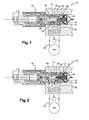
- Said OCV 10 comprises a housing 12, a spool 14 located in the housing 12, and a control unit 16 for controlling the position of the spool 14 in the housing 12.
- Said spool 14 is slidably mounted along a longitudinal axis Al in the housing 12, between a front position ( fig. 1 ) and a rear position ( fig. 2 ).
- a spring 18 is inserted between the spool rear end 20 and the housing rear end 22 in order to biase the spool 14 towards its front position.
- Said housing 12 is provided with fluid supply inlets 24 in its rear portion 26.
- a radial rear port 28 and a radial front port 30 are in communication with the hydraulic circuit 32 of the cam phaser 34.
- a radial vent port 36, or drain port, is arranged between the rear port 28 and the front port 30, said vent port 36 being in communication with an oil reservoir.
- Said spool 14 is provided with grooves and channels which intersect accordingly with said ports 28, 30, 36 of the housing 12 in order to route the fluid based on the spool's position.
- the control unit 16 is constituted of a solenoid actuator which, when energized, engages the spool front end 38 such as to move the spool 14 towards its rear position against the spring biasing.
- Such a bottom feed OCV has sensitivity to hydraulic forces applied to the spool.
- a high supply pressure is set and when the valve is in advance mode, instead of having a higher flow, as expected when the supply pressure goes up, the flow goes down. This is explained by the hydraulic force applied to the spool for high supply pressure. It pushes the spool against the magnetic force, in the same direction as the spring force, which reduces the flow.
- the present invention aims at solving the above mentioned problem in order to improve controllability and reliability of the OCV.
- an oil flow control valve for a cam phaser comprising a housing, a spool located in the housing, and a control unit for controlling the position of the spool in the housing, said spool being slidably mounted along a longitudinal axis in the housing, between a front position and a rear position, a spring being inserted between the spool rear end and the housing rear end in order to biased the spool towards its front position, said housing being provided with a fluid supply inlet in its rear portion, a radial rear port and a radial front port in communication with the hydraulic circuit of the cam phaser, and a radial vent port arranged between the rear port and the front port, said vent port being in communication with a oil reservoir, said spool being provided with grooves and channels which intersect accordingly with said ports of the housing in order to route the fluid based on the spool's position, characterized in that said spool rear end and the spool front end delimit, within the housing
- This invention is giving a technical solution to balance the hydraulic force for a bottom feed OCV.
- the design of the spool is such that the two ends are not exposed to the supply pressure, but to the vent pressure which corresponds generally to the atmospheric pressure. This prevents a differential pressure to apply on each end of the spool, the hydraulic force being balanced inside the spool.
- FIG 3 shows an OCV 10 for controlling the oil flow from an oil supply channel 42, connectable to a source of high pressure oil, into a cam phaser 34 of an internal combustion engine.
- the OCV 10 is generally mounted in a longitudinal bore 44 in the engine cylinder head 46.
- the OCV 10 comprises a housing 12, a spool 14 located in the housing 12, and a control unit 16 for controlling the position of the spool 14 in the housing 12 along a longitudinal axis A1, between extreme front and rear positions shown respectively on figures 3 and 4 .
- the housing 12 of the OCV 10 is formed like a cylindrical sleeve comprising radial ports 28, 30, 36 which are in communication with corresponding oil channels 48, 50, 52 arranged in the cylinder head 46.
- these channels 48, 50, 52, the rear one 48 and the front one 50 are typically used to supply alternatively the cam phaser 34 with oil for moving the cam phaser 34 between advanced and retarded positions, and the central one is a vent channel 52 back to the engine oil sump or oil reservoir 54.
- the oil flow through the OCV 10 and the channels 48, 50, 52 is essentially controlled by the longitudinal position of the spool 14 which is reciprocally mounted in the housing 12, as is well known in the art.
- the placement of the spool 14 in the housing 12 is controlled by the control unit 34, which preferably includes a solenoid actuator.
- the control unit 34 includes an actuating stem 56 which extends longitudinally and engages the spool front end surface 38 and which, when actuated, biases the spool 14 towards its extreme rear position against the biasing of a spring 18 inserted between the spool rear end 20 and the housing rear end 22.
- the spring 18 biases the spool 14 towards its extreme front position.
- the housing 12 is provided with oil supply inlets 24, formed as radial bores, in its rear portion 26.
- the rear portion 26 of the housing 12 is essentially cylindrical, having an outer diameter smaller than the inner diameter of the longitudinal bore 44 in order to allow the oil to flow from the oil supply channel 42 to the inner part of the housing 12 through said oil supply inlets 24.
- the rear portion 26 is provided with filtering means 58.
- the spool 14 which is shown independently on figure 6 , has a substantially cylindrical body provided with grooves and channels which intersect accordingly with the ports 28, 30, 36 of the housing 12 in order to route the oil flow based on the spool's position.
- the spool 14 includes a main longitudinal bore 60, or channel, which is of elongated shape and which extends longitudinally from a rear end wall 62 to a front end wall 64 of the spool 14.
- Said main longitudinal bore 60 includes a rear radial inlet 66 facing substantially at least one of the housing supply inlets 24 such that the oil flowing through the housing supply inlets 24 goes into the main longitudinal bore 60 of the spool 14 whatever is the longitudinal position of the spool 14.
- Said main longitudinal bore 60 also includes a front radial outlet 68 facing at least partly the housing front port 30 only when the spool 14 is in its rear position ( figure 4 ), said front radial outlet 68 facing the inner surface of a front portion of the housing 12 when the spool 14 is in its front position ( figure 3 ).
- the rear inlet 66 and the front outlet 68 of the spool 14 are each surrounded rearward and frontward by cylindrical portions 70 being a tight sliding fit against the inner surface of the housing 12.
- the spool 14 has a circumferential intermediate groove 72 which is facing the housing vent port 36 and which communicates alternatively either with the housing front port 30, when the spool 14 is in its front position, or with the housing rear port 28, when the spool 14 is in its rear position.
- the spool rear ends delimit, within the housing 12, respectively a rear end cavity 74 wherein said spring 18 is mounted and a front end cavity 76 wherein said actuator stem 56 engages the spool 14.
- Said rear end cavity 74 and said front end cavity 76 are in communication with said oil reservoir 54 and are isolated from the fluid supply pressure coming from the oil supply channel 42.
- the longitudinal dimension of each cavity 74, 76 is variable, depending on the spool's position.
- the rear end cavity 74 is delimited frontward by the spool rear end wall 62, which is made of one piece with the spool body, and rearward by a rear cap 78, or plug, which is mounted at the housing rear end in order to close the rear side of the rear portion 26 and in order to form a spring retainer for said spring 18.
- the longitudinal distance between the housing supply inlets 24 and the rear cap 78 has to be chosen such that the rear end cavity 74 is isolated from the oil supply pressure even when the spool 14 is in its front position.
- the front end cavity 76 is delimited rearward by the front end wall 64 of the spool 14, which is made of a front cap mounted at the spool front end in order to close the main longitudinal bore 60 of the spool 14, and frontward by the control unit 16.
- the rear cap 78 and the front cap 64 can be press fitted in respectively the housing 12 and the spool 14.
- both cavities 74, 76 are connected to said oil reservoir 54 through said vent port 36 thanks to a longitudinal through channel 80 extending in the spool body, in parallel to the main longitudinal bore 60.
- said through channel 80 opens longitudinally to each cavity 74, 76 and has a radial through hole 82 which opens to the vent port 36, said radial through hole 82 being arranged substantially in an intermediate longitudinal position between both ends of the spool 14.
- the cavities 74, 76 are isolated from the high pressure fluid passing from the supply inlets 24 to the housing rear and front ports 28, 30 and are connected only to the vent pressure.
- the vent pressure corresponds generally to the atmospheric pressure.
- the oil flow circuit is schematically represented with arrows F1 on figures 3, 4 , and 5 .
- the solenoid is not energized and the spool 14 is in its front position.
- the oil supply channel 42 feeds the valve 10 with oil at high pressure.
- the oil flow enters into the housing 12 and into the spool 14 through the housing supply inlets 24 and through the spool rear inlet 66. Since the spool rear inlet 66 is in communication with the housing rear port 28, and since the spool front outlet 68 is facing the housing inner surface, the oil can only flow to the rear channel 48.
- the oil goes back to the valve 10 through the front channel 50 and the housing front port 30.
- the housing front port 30 being in communication with the vent port 36 through the spool groove 72, the oil flows back to the oil reservoir 54 through the vent channel 52.
- the solenoid is energized such that the spool 14 slides towards its rear position, against the spring return force.
- the oil supply channel 42 feeds the valve with oil at high pressure.
- the oil flow enters into the housing 12 and into the spool 14 through the housing supply inlets 24 and through the spool rear inlet 66. Since the spool rear inlet 66 is not in communication with the housing rear port 28, and since the spool front outlet 68 is in communication with the housing front port 30, the oil can only flow to the front channel 50.
- the oil goes back to the valve 10 through the rear channel 48 and the housing rear port 28.
- the housing rear port 28 being in communication with the vent port 36 through the spool groove 72, the oil flows back to the oil reservoir 54 through the vent channel 52.
- the pressure applying on the front end surface of the spool 14 and on the rear end surface of the spool 14 is always the vent pressure which brings equilibrium for the control of the spool 14. Therefore, in advance mode, the actuator has only to provide enough pressure on the spool 14 for compressing the spring 18. On contrary to the prior art, the increase in oil supply pressure does not create hydraulic force acting against the actuator force.
Landscapes
- Engineering & Computer Science (AREA)
- General Engineering & Computer Science (AREA)
- Mechanical Engineering (AREA)
- Valve Device For Special Equipments (AREA)
- Multiple-Way Valves (AREA)
Priority Applications (5)
| Application Number | Priority Date | Filing Date | Title |
|---|---|---|---|
| EP09167446A EP2295740A1 (fr) | 2009-08-07 | 2009-08-07 | Soupape de contrôle de débit d'huile à alimentation inférieure pour synchronisateur de phase de cames |
| PCT/EP2010/059780 WO2011015418A1 (fr) | 2009-08-07 | 2010-07-08 | Vanne de commande de débit dhuile dalimentation par le bas pour dispositif de mise en phase de came |
| CN201080034812.8A CN102472129B (zh) | 2009-08-07 | 2010-07-08 | 用于凸轮相位器的底部供给油流控制阀 |
| EP10732345.3A EP2462324B1 (fr) | 2009-08-07 | 2010-07-08 | Soupape de contrôle de débit d'huile à alimentation inférieure pour synchronisateur de phase de cames |
| KR1020127002350A KR101352888B1 (ko) | 2009-08-07 | 2010-07-08 | 오일 흐름 제어 밸브 |
Applications Claiming Priority (1)
| Application Number | Priority Date | Filing Date | Title |
|---|---|---|---|
| EP09167446A EP2295740A1 (fr) | 2009-08-07 | 2009-08-07 | Soupape de contrôle de débit d'huile à alimentation inférieure pour synchronisateur de phase de cames |
Publications (1)
| Publication Number | Publication Date |
|---|---|
| EP2295740A1 true EP2295740A1 (fr) | 2011-03-16 |
Family
ID=41323416
Family Applications (2)
| Application Number | Title | Priority Date | Filing Date |
|---|---|---|---|
| EP09167446A Withdrawn EP2295740A1 (fr) | 2009-08-07 | 2009-08-07 | Soupape de contrôle de débit d'huile à alimentation inférieure pour synchronisateur de phase de cames |
| EP10732345.3A Not-in-force EP2462324B1 (fr) | 2009-08-07 | 2010-07-08 | Soupape de contrôle de débit d'huile à alimentation inférieure pour synchronisateur de phase de cames |
Family Applications After (1)
| Application Number | Title | Priority Date | Filing Date |
|---|---|---|---|
| EP10732345.3A Not-in-force EP2462324B1 (fr) | 2009-08-07 | 2010-07-08 | Soupape de contrôle de débit d'huile à alimentation inférieure pour synchronisateur de phase de cames |
Country Status (4)
| Country | Link |
|---|---|
| EP (2) | EP2295740A1 (fr) |
| KR (1) | KR101352888B1 (fr) |
| CN (1) | CN102472129B (fr) |
| WO (1) | WO2011015418A1 (fr) |
Cited By (1)
| Publication number | Priority date | Publication date | Assignee | Title |
|---|---|---|---|---|
| WO2016129058A1 (fr) * | 2015-02-10 | 2016-08-18 | 三菱電機株式会社 | Vanne de commande |
Families Citing this family (9)
| Publication number | Priority date | Publication date | Assignee | Title |
|---|---|---|---|---|
| DE102012106096B3 (de) * | 2012-07-06 | 2014-05-15 | Hilite Germany Gmbh | Schwenkmotorversteller mit einem Hydraulikventil |
| US9121311B2 (en) * | 2013-10-25 | 2015-09-01 | GM Global Technology Operations LLC | Control valve |
| DE102014011088B3 (de) * | 2014-07-30 | 2016-01-28 | Hilite Germany Gmbh | Hydraulikventil für einen Schwenkmotorversteller |
| WO2017050327A1 (fr) * | 2015-09-21 | 2017-03-30 | Schaeffler Technologies AG & Co. KG | Soupape de commande pour un déphaseur d'arbre à cames |
| US11078816B2 (en) | 2016-10-10 | 2021-08-03 | Unick Corporation | Oil pump control valve |
| DE102017124485A1 (de) * | 2017-10-19 | 2019-04-25 | Eto Magnetic Gmbh | Elektromagnetische Aktuatorvorrichtung und Verwendung einer solchen |
| CN112384681B (zh) * | 2018-09-20 | 2022-09-09 | 舍弗勒技术股份两合公司 | 用于凸轮轴相位器的储油器 |
| CN109373037B (zh) * | 2018-11-14 | 2024-03-26 | 宁波太平洋电控系统有限公司 | 一种带有凸轮轴润滑结构的中央阀阀套 |
| CN109945060B (zh) * | 2019-03-15 | 2020-09-01 | 中国航发湖南动力机械研究所 | 集成式滑油压力调节装置 |
Citations (5)
| Publication number | Priority date | Publication date | Assignee | Title |
|---|---|---|---|---|
| US20020134444A1 (en) * | 2001-03-26 | 2002-09-26 | Eiji Isobe | Solenoid valve |
| US6668778B1 (en) * | 2002-09-13 | 2003-12-30 | Borgwarner Inc. | Using differential pressure control system for VCT lock |
| US20040211312A1 (en) * | 1999-02-11 | 2004-10-28 | Ina Walzlager Schaeffler Ohg | Camshaft control device and control valve with leakage compensation |
| GB2409538A (en) * | 2003-12-26 | 2005-06-29 | Denso Corp | Stopper between electromagnetic spool valve and bracket |
| US20080066572A1 (en) * | 2006-09-15 | 2008-03-20 | Denso Corporation | Valve timing control system |
Family Cites Families (1)
| Publication number | Priority date | Publication date | Assignee | Title |
|---|---|---|---|---|
| JP4253635B2 (ja) * | 2004-11-30 | 2009-04-15 | トヨタ自動車株式会社 | シリンダヘッドカバー |
-
2009
- 2009-08-07 EP EP09167446A patent/EP2295740A1/fr not_active Withdrawn
-
2010
- 2010-07-08 CN CN201080034812.8A patent/CN102472129B/zh not_active Expired - Fee Related
- 2010-07-08 KR KR1020127002350A patent/KR101352888B1/ko active IP Right Grant
- 2010-07-08 WO PCT/EP2010/059780 patent/WO2011015418A1/fr active Application Filing
- 2010-07-08 EP EP10732345.3A patent/EP2462324B1/fr not_active Not-in-force
Patent Citations (5)
| Publication number | Priority date | Publication date | Assignee | Title |
|---|---|---|---|---|
| US20040211312A1 (en) * | 1999-02-11 | 2004-10-28 | Ina Walzlager Schaeffler Ohg | Camshaft control device and control valve with leakage compensation |
| US20020134444A1 (en) * | 2001-03-26 | 2002-09-26 | Eiji Isobe | Solenoid valve |
| US6668778B1 (en) * | 2002-09-13 | 2003-12-30 | Borgwarner Inc. | Using differential pressure control system for VCT lock |
| GB2409538A (en) * | 2003-12-26 | 2005-06-29 | Denso Corp | Stopper between electromagnetic spool valve and bracket |
| US20080066572A1 (en) * | 2006-09-15 | 2008-03-20 | Denso Corporation | Valve timing control system |
Cited By (1)
| Publication number | Priority date | Publication date | Assignee | Title |
|---|---|---|---|---|
| WO2016129058A1 (fr) * | 2015-02-10 | 2016-08-18 | 三菱電機株式会社 | Vanne de commande |
Also Published As
| Publication number | Publication date |
|---|---|
| CN102472129A (zh) | 2012-05-23 |
| EP2462324A1 (fr) | 2012-06-13 |
| CN102472129B (zh) | 2014-03-05 |
| EP2462324B1 (fr) | 2013-05-15 |
| KR101352888B1 (ko) | 2014-01-20 |
| KR20120039673A (ko) | 2012-04-25 |
| WO2011015418A1 (fr) | 2011-02-10 |
Similar Documents
| Publication | Publication Date | Title |
|---|---|---|
| EP2462324B1 (fr) | Soupape de contrôle de débit d'huile à alimentation inférieure pour synchronisateur de phase de cames | |
| EP1672184B1 (fr) | Soupape de contrôle d'un arbre de cames variable avec contrôle d'un pion de blocage | |
| KR101084960B1 (ko) | 캠 토션이 작은 엔진 조건에서 작동하기 위한 비례 오일 압력을 가진 씨티에이 페이저 | |
| US20180266283A1 (en) | Variable camshaft timing mechanism with a lock pin engaged by oil pressure | |
| US8356583B2 (en) | Variable camshaft timing device with hydraulic lock in an intermediate position | |
| KR20170026238A (ko) | 다모드 가변 캠 타이밍 페이저 | |
| US8220427B2 (en) | VCT active lock pin control | |
| US20090107432A1 (en) | Cylinder valve operating system for reciprocating internal combustion engine | |
| US20110162605A1 (en) | Cam torque actuated phaser using band check valves built into a camshaft or concentric camshafts | |
| US7367356B2 (en) | Oil flow control valve for a cam phaser | |
| US20100084019A1 (en) | Central spool valve | |
| KR20150123871A (ko) | 양방향 유압 바이어스 회로를 구비한 캠 토크 작동식 가변 캠샤프트 타이밍 장치 | |
| US7370617B2 (en) | Variable valve operating mechanism of four-stroke internal combustion engine | |
| WO2016021280A1 (fr) | Valve oléo-hydraulique, et dispositif de commande de réglage de distribution pour moteur à combustion interne mettant en œuvre une valve oléo-hydraulique | |
| WO2008140897A1 (fr) | Accumulateur monté sur came | |
| EP2899377B1 (fr) | Appareil de commande du réglage de distribution variable | |
| US8899199B1 (en) | Camshaft phaser and lock pin thereof | |
| KR20130089603A (ko) | 캠축 조정 장치 | |
| KR20030096051A (ko) | 베인 스타일 캠 페이저에서의 핀 로크의 견고한 작동을보장하는 방법 | |
| WO2016021328A1 (fr) | Valve oléo-hydraulique, et dispositif de commande de réglage de distribution pour moteur à combustion interne mettant en œuvre une valve oléo-hydraulique | |
| JP2018091226A (ja) | 弁開閉時期制御装置 | |
| EP2050934B1 (fr) | Soupape de contrôle de débit d'huile pour synchronisateur de phase de cames | |
| EP2363579A1 (fr) | Öldurchflussregelventil mit zwei Rückschlagventilen | |
| JP6369253B2 (ja) | 弁開閉時期制御装置 | |
| US6631700B2 (en) | Dual oil feed variable timed camshaft arrangement |
Legal Events
| Date | Code | Title | Description |
|---|---|---|---|
| PUAI | Public reference made under article 153(3) epc to a published international application that has entered the european phase |
Free format text: ORIGINAL CODE: 0009012 |
|
| AK | Designated contracting states |
Kind code of ref document: A1 Designated state(s): AT BE BG CH CY CZ DE DK EE ES FI FR GB GR HR HU IE IS IT LI LT LU LV MC MK MT NL NO PL PT RO SE SI SK SM TR |
|
| AX | Request for extension of the european patent |
Extension state: AL BA RS |
|
| STAA | Information on the status of an ep patent application or granted ep patent |
Free format text: STATUS: THE APPLICATION IS DEEMED TO BE WITHDRAWN |
|
| 18D | Application deemed to be withdrawn |
Effective date: 20110917 |