EP2295718A2 - Eigenständiges Frac-Liner-System - Google Patents
Eigenständiges Frac-Liner-System Download PDFInfo
- Publication number
- EP2295718A2 EP2295718A2 EP10251348A EP10251348A EP2295718A2 EP 2295718 A2 EP2295718 A2 EP 2295718A2 EP 10251348 A EP10251348 A EP 10251348A EP 10251348 A EP10251348 A EP 10251348A EP 2295718 A2 EP2295718 A2 EP 2295718A2
- Authority
- EP
- European Patent Office
- Prior art keywords
- liner
- frac
- well
- fracturing
- stand
- Prior art date
- Legal status (The legal status is an assumption and is not a legal conclusion. Google has not performed a legal analysis and makes no representation as to the accuracy of the status listed.)
- Granted
Links
Images


Classifications
-
- E—FIXED CONSTRUCTIONS
- E21—EARTH OR ROCK DRILLING; MINING
- E21B—EARTH OR ROCK DRILLING; OBTAINING OIL, GAS, WATER, SOLUBLE OR MELTABLE MATERIALS OR A SLURRY OF MINERALS FROM WELLS
- E21B41/00—Equipment or details not covered by groups E21B15/00 - E21B40/00
- E21B41/0035—Apparatus or methods for multilateral well technology, e.g. for the completion of or workover on wells with one or more lateral branches
-
- E—FIXED CONSTRUCTIONS
- E21—EARTH OR ROCK DRILLING; MINING
- E21B—EARTH OR ROCK DRILLING; OBTAINING OIL, GAS, WATER, SOLUBLE OR MELTABLE MATERIALS OR A SLURRY OF MINERALS FROM WELLS
- E21B33/00—Sealing or packing boreholes or wells
- E21B33/02—Surface sealing or packing
- E21B33/03—Well heads; Setting-up thereof
- E21B33/068—Well heads; Setting-up thereof having provision for introducing objects or fluids into, or removing objects from, wells
-
- E—FIXED CONSTRUCTIONS
- E21—EARTH OR ROCK DRILLING; MINING
- E21B—EARTH OR ROCK DRILLING; OBTAINING OIL, GAS, WATER, SOLUBLE OR MELTABLE MATERIALS OR A SLURRY OF MINERALS FROM WELLS
- E21B43/00—Methods or apparatus for obtaining oil, gas, water, soluble or meltable materials or a slurry of minerals from wells
- E21B43/25—Methods for stimulating production
- E21B43/26—Methods for stimulating production by forming crevices or fractures
Definitions
- Embodiments described relate to a system for fracturing multiple lateral legs of a conventional multilateral well.
- tools and techniques are described that allow for the placement of multiple stand-alone frac liners in multiple lateral legs.
- subsequent fracturing of each leg may take place without requiring intervening removal of fracturing surface equipment.
- the terminal end of a cased well often extends into an open-hole lateral leg section. Additionally, such open-hole lateral legs are often found extending from other regions of the main vertical well bore. Such architecture may enhance access to the reservoir, for example, where the reservoir is substantially compartmentalized. Regardless, such open-hole lateral leg sections often present their own particular challenges when it comes to their completions and maintenance.
- Fracturing applications generally during well completion, constitute one area where significant amounts of time and effort are spent, particularly as increases in well depths and sophisticated architecture are encountered. Indeed, where a host of lateral legs are present as described above, a considerable amount of time and effort may be spent dedicated to fracturing of each individual leg. Once more, as described below, this expenditure of time and effort may be exacerbated by the particular sequential procedures that are required as a result of conventionally available frac equipment.
- Fracturing of a lateral leg involves positioning surface fracturing equipment at the oilfield and hooking it up to the well.
- a frac string tubular terminating in a liner for positioning in the lateral leg may then be advanced to the leg for the fracturing application.
- a deflector may be pre-positioned in the main bore of the well for such guidance.
- the frac string tubular may be removed and the well tested, with focus on flow of the fractured lateral leg. Subsequently, the surface fracturing equipment may be reset, the frac string tubular outfitted with another frac liner, and the process repeated at another lateral leg.
- each leg of a multilateral well may be effectively fractured according to techniques such as those described above.
- the amount of time and effort spent on setting and re-setting surface fracturing equipment is quite significant. For example, once the initial fracturing takes place in the first lateral leg, subsequent testing, potential clean-out and other treatment of the leg closely follows. This requires the removal and replacement of the large fracturing equipment coupled to the well at the oilfield surface. Additionally, with the follow-on testing and potential treatment of the lined lateral leg, it is unlikely that a subsequent fracturing of another leg will take place in less than a few weeks.
- a method is described of utilizing multiple or "stacked" stand-alone frac liners in lateral legs off a main well bore.
- the method includes setting first and second stand-alone frac liners in first and second lateral legs. Frac equipment may then be employed for directing a fracturing application through one of the liners.
- a frac string tubular may be coupled to the one of the liners for the fracturing application. This tubular may be kept in the well and coupled to the other liner. Thus, a subsequent fracturing application may be performed through this other liner.
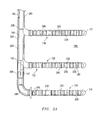
- Fig. 1 is an overview of an oilfield with a multi-frac liner system installed in multiple lateral legs of a well through a formation.
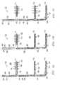
- Fig. 2A is an enlarged view of the well and formation of Fig. 1 revealing the installation of a downhole expansion joint at a downhole liner of the system.
- Fig. 2B is an enlarged view of a deflector of the expansion joint of Fig. 2A at a junction of the main bore and a lateral leg of the well for aiding installation of a central expansion joint.
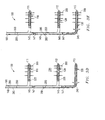
- Fig. 3A is a side view of the installed system of Fig. 1 , with a fracturing application applied to an uphole lateral leg through an uphole liner.
- Fig. 3B is a side view of the system of Fig. 3A , with a running tool of an uphole expansion joint disengaged from the uphole liner and drawn into the main bore.
- Fig. 3C is a side view of the system of Fig. 3B with the running tool of the uphole expansion joint engaged with the deflector of the central expansion joint for fracturing of the central lateral leg through the central liner.
- Fig. 3D is a side view of the system of Fig. 3C with a running tool of the central expansion joint disengaged from the uphole liner and drawn into the main bore.
- Fig. 3E is a side view of the system of Fig. 3D with the running tool of the central expansion joint engaged with the deflector of the downhole expansion joint for fracturing of the downhole lateral leg through the downhole liner.
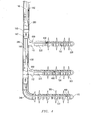
- Fig. 4 is a side cross-sectional view of the system of Fig. 3E revealing a flow of produced hydrocarbons therethrough.
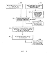
- Fig. 5 is a flow chart summarizing an embodiment of employing a multi-frac liner system in a multi-lateral well.
- Embodiments are described with reference to certain multilateral well architectures and multi-frac sequential operations. For example, embodiments herein are detailed with reference to a particular tri-lateral well architecture. Additionally, lateral legs of the well are outfitted with frac liners and subsequent expansion joints in particular sequences described below. However, fracturing of multilateral wells according to embodiments described herein may be applied to a variety of different well architectures. Further, the particular sequence of positioning the system may vary. For example, in one embodiment, expansion joints and frac liners may be positioned simultaneously as opposed to sequentially. Regardless, embodiments described herein include a system of stand-alone frac liners for a multilateral well that allows fracturing at one lateral leg to be followed by fracturing at another without the requirement of intervening frac equipment removal, particularly at surface.
- FIG. 1 an overview of an oilfield 150 is shown with a multi-frac liner system 100 installed in a well 180. More specifically, the system 100 includes several frac liners 110, 120, 130 positioned within multiple lateral legs 111, 112, 113 of the well 180. The well 180 traverses various formation layers 190, 195. However, the multiple lateral legs 111, 112, 113 are directed at a particular production layer 195, for example, where a compartmentalized reservoir may be targeted.
- a rig 170 is positioned over a well head 176 at the surface of the oilfield 150 where a variety of surface equipment may be located for various applications to the well 180.
- drill pipe 175 and support structure 179 are depicted as part of initial operations in positioning the multi-frac liner system 100 shown.
- An engine 177 for powering downhole placement is also shown.
- a fracturing line 178 is shown coupled to the well head 176 for fracturing as detailed in Figs. 3A-3E below. This line 178 may in turn be coupled to a manifold and various frac pumps for generating high pressure for such fracturing.
- the high pressure line 178 and other fracturing surface equipment may remain in place between fractures of different lateral legs 111, 112, 113 due to the nature of stand-alone frac liners 120, 130 of the system 100. That is, as shown, the uphole frac liner 110 may be coupled to a frac string tubular 160 running to surface. In the embodiment shown, this is achieved through an uphole expansion joint 148 which accommodates a running tool 145 at its end. However, as shown, the central 120 and downhole 130 frac liners are even more visibly stand-alone in nature. That is, upon installation, the liners 120, 130 are positioned in their respective lateral legs 112, 113 without maintaining physical communication with the surface. Thus, as detailed below, running tools 145 may be successively decoupled from liners 110, 120 and used to couple to deflectors 147 therebelow for sequential fracturing of the legs 111, 112, 113.
- a main bore 285 of the well 180 may be drilled according to conventional techniques and terminating in a downhole lateral leg 113.
- a casing 280, various index couplings 200 and other features may subsequently be provided as depicted in Figs. 2A & 2B .
- the downhole lateral leg 113 may remain primarily open-hole in nature.
- the liner 130 for this leg 113 may be installed via conventional techniques even before the other legs 111, 112 are drilled. Subsequent whipstock placement at index couplings 200 may be used to guide drilling of these other legs 111, 112, followed by placement of the respective liners 120, 130, generally working from downhole up.
- FIG. 2A an enlarged view of the well 180 and formation 195 of Fig. 1 are shown.
- the installation of a downhole expansion joint 249 at the downhole liner 130 is depicted.
- the joint 249 is coupled to the liner hanger 245, a conventional anchor mechanism generally available at the interface of downhole end of casing 280 and a downhole liner 130.
- the deflector 147 at the other end of this joint 249 may be delivered into position at the index coupling 200 by a running tool 145 of the central joint 148.
- the tool 145 and joint 148 may subsequently be repositioned to allow delivery of the joint 148 to the central liner 120.
- Fig. 2A also reveals features of the liners 110, 120, 130 in greater detail.
- the liners 110, 120, 130 are equipped with separate fracture housings 220.
- These housings 220 may include an internal sliding sleeve for internal exposure of the liners 110, 120, 130 to the legs 111, 112, 113 through orifices 230. Such exposure may be employed during fracturing and production as described further herein. Nevertheless, a given zone occupied by a given housing 220 may be isolated by conventional packers 240.
- FIG. 2B an enlarged view of a junction 275 of the main bore 285 and the central lateral leg 112 of the well 180 is depicted.
- the deflector 147 of the downhole expansion joint 249 of Fig. 2A is shown with the running tool 145 of the central joint 149 disengaged therefrom. Rather, as described further below, the tool 145 is repositioned about a latch coupling 225 at the uphole end of the central frac liner 120.
- the downhole expansion joint 249 is placed followed by placement of the central expansion joint 149. While a variety of techniques may be employed, in the embodiments described, all of the joints 148, 149, 249 are initially positioned in the main bore 285 of the well 180 linked to one another as a uniform assembly. Thus, following positioning of the most downhole joint (i.e. the dowhole expansion joint, 249) as shown in Fig. 2A , the central joint 149 may be placed as depicted in Fig. 2B .
- the above noted repositioning is achieved by rotatable decoupling of the central running tool 145 from the downhole deflector 147 as guided by the depicted index coupling 200. That is, the vertically oriented uphole 148 and central 149 expansion joints may be rotated from the oilfield surface 150. Thus, the central running tool 145 may be rotatably disengaged from the downhole deflector 147 and its joint 249, due to its vertical positioning (see Fig. 2A ). As this takes place, the index coupling 200 may be employed to provide orientation information regarding the tool 145 in conjunction with its decoupling from the deflector 147. Once more, the changed orientation of the tool 145 which allows for the decoupling also allows for its deflection into the central leg 112.
- the deflector 147 is configured such that reinsertion of the newly oriented tool 145 and central joint 149 lead to deflection thereof into the central leg 112 as shown. Indeed, this process may be repeated for placement of the uphole joint 148, ultimately resulting in the stacked multilateral frac liner system 100 apparent in Fig. 1 .
- FIGs. 3A-3E one embodiment of sequentially fracturing multiple lateral legs 111, 112, 113 with the fully installed stacked frac liner system 100 is described. Perhaps most notably, the prepositioning of stand-alone liners 110, 120, 130 in advance of fracturing, allows for operations to take place without removal of the frac string tubular 160 or fracture line 178 and equipment replacement between separate leg fractures (see Fig. 1 ). Thus, a fair amount of time and a substantial amount of manpower and expense may be saved.
- a side view of the installed system 100 is depicted as described above. This view is similar to that of Fig. 1 . However, in this depiction, fractures 300 are shown at the uphole leg 111. That is, with added reference to Fig. 1 , the frac string tubular 160 is in direct communication with the uphole lateral leg 111 upon installation of the entire system 100. Thus, a fracturing application may take place through the tubular 160, uphole extension joint 148 and liner 110. This fracturing may take place via conventional techniques with internal sliding sleeves and seals 240 of the liner 110 guiding fracturing into the formation 195 and isolation in terms of flow.
- fracturing of the main bore 285 may precede fracturing of the uphole leg 111.
- each expansion joint 148, 149, 249 may be outfitted with a ported fracture housing 350.
- isolation may be provided by the innermost seals 240 of the liners 110, 120, 130 and conventional sealing above the housing 350.
- adjacent sliding sleeves or perforations in the casing 280 may allow for effective vertical fracturing of the main bore 285 in advance of the uphole lateral leg 111.
- a small amount of recovery and/or production may take place directly through the liner 110 and uphole joint 148. Additionally, an additional conventional internal seal may be provided near the latch coupling 225 to isolate the uphole leg 111 until later production operations (see Fig. 3B ).
- a side view of the system 100 of Fig. 3A is depicted.
- a running tool 145 of the uphole expansion joint 148 is shown disengaged from the uphole liner 110 and drawn into the main bore 285 of the well 180.
- the manner of tool disengagement may be a matter of rotation as guided by and accounted for by the index coupling 200 associated with the uphole expansion joint 148 and running tool 145.
- FIG. 3C a side view of the system 100 of Fig. 3B is shown with the uphole running tool 145 now engaged with the central deflector 147 of the central expansion joint 149.
- fracturing of the central lateral leg 112 through the central liner 120 is also depicted.
- the orientation and locking of the tool 145 at the deflector 147 may proceed with the guidance of the appropriate index coupling 200 as detailed above.
- fracturing of the main bore 285, in this case through the ported fracture housing 350 of the central expansion joint 149 may precede the central leg 112 fracturing as depicted.
- a small amount of recovery and/or production may again take place directly through the liner 120 and central joint 148. Further, an additional conventional internal seal may be provided near the latch coupling 225 to isolate the central leg 112 until later production operations (see Fig. 3D ).
- Fig. 3D the steps of moving to the next downhole leg for fracturing are repeated. That is, in this depiction the running tool 145 of the central expansion joint 149 is shown disengaged from the central liner 120 and drawn into the main bore 285 of the well 180. Again, the manner of tool disengagement may be a matter of rotation as guided by and accounted for by the relevant index coupling 200 associated with the central expansion joint 149 and running tool 145.
- Fig. 3E the system 100 of Fig. 3B is shown with the central running tool 145 now engaged with the downhole deflector 147 of the downhole expansion joint 249.
- fracturing of the downhole lateral leg 113 through the downhole liner 130 is also depicted.
- the orientation and locking of the tool 145 at the deflector 147 may again proceed with the guidance of the appropriate index coupling 200 as detailed above.
- the downhole expansion joint 249 is not outfitted a ported fracture housing.
- a ported fracture housing may be provided for fracturing above and in advance of the downhole leg 113.
- FIG. 4 a side cross-sectional view of the system 100 of Fig. 3E is shown following fracturing of each lateral leg 111, 112, 113 as detailed above. Additionally, in this view, a flow 400 of produced hydrocarbons is shown emanating from each leg 111, 112, 113 and through the system 100. More specifically, a flow 400 from the downhole liner 130 is depicted interior of the downhole joint 249 whereas the flow 400 from the uphole 110 and central 120 liners openly empties into the main bore 285 for uphole travel.
- fracturing operations such production and flow as depicted in Fig. 4 may be utilized to ensure the effectiveness of the stacked multi-lateral fracturing that has taken place on a single call out of fracturing equipment. That is, a flow back of all of the lateral legs 111, 12, 113 may take place simultaneously. Thus, the amount of time spent testing in advance of production may be substantially reduced.
- the uphole 110 and central 120 liners are left interiorly unsealed at their respective latch couplings 225.
- production is taking place through the fracturing equipment, including expansion joints 148, 149, 249, running tools 145 and deflectors 147.
- the fracturing equipment in the well 180 may be replaced with more conventional production equipment as described below.
- the joints 148, 149, 249 may be replaced with production tubing coupled to the downhole liner 130 and equipped with sliding sleeves for communication with the uphole 110 and central 120 liners.
- the production tubing may be terminally anchored by a packer positioned above the lateral legs 111, 112, 113 and open to the main bore 285 as are each of the liners 110, 120, 130.
- flow 400 may openly proceed uphole from each of the liners 110, 120, 130 through the main bore 285 and into the production tubing.
- thru tubing may be provided between each of the liners 110, 120, 130 and production tubing in the main bore 285.
- discrete and direct flow 400 may take place between each liner 110, 120 , 130 and production tubing.
- a flow chart summarizing an embodiment of employing a multi-frac liner system in a multi-lateral well is shown.
- a single call out of fracturing equipment may take place as indicated at 520 even though multiple lateral legs of a well are to be fractured.
- this efficiency is afforded by the placement of stand-alone frac liners in multiple lateral legs of the well. This may include the placement of expansion joints between these liners and the main bore of the well. Alternatively, as indicated at 540, the expansion joints may be separately provided.
- one of the legs may be fractured via its stand-alone frac liner as indicated at 550.
- hydrocarbons may initially be produced from this leg (see 560).
- a running tool that is in communication with the oilfield surface may be repositioned from coupling to the liner in the first leg to coupling to a liner in a second leg.
- the second leg may be fractured via the liner therein. Notably, this takes place without the requirement of intervening positioning and re-positioning of fracturing equipment at the oilfield surface.
- hydrocarbons may be produced from this second leg, for example as a test of fracturing effectiveness, even in advance of production tubing placement.
- Embodiments described hereinabove provide tools and techniques for fracturing of multilateral wells without the requirement of positioning and repositioning massive fracturing equipment at the oilfield surface. Rather, through the use of a stacked and prepositioned, stand-alone frac liner system, a lateral fracturing application may be followed by brief production, testing and hookup for a successive lateral fracture without the requirement of fracturing equipment removal.
Landscapes
- Life Sciences & Earth Sciences (AREA)
- Engineering & Computer Science (AREA)
- Geology (AREA)
- Mining & Mineral Resources (AREA)
- Physics & Mathematics (AREA)
- Environmental & Geological Engineering (AREA)
- Fluid Mechanics (AREA)
- General Life Sciences & Earth Sciences (AREA)
- Geochemistry & Mineralogy (AREA)
- Earth Drilling (AREA)
- Pens And Brushes (AREA)
Applications Claiming Priority (3)
| Application Number | Priority Date | Filing Date | Title |
|---|---|---|---|
| US21394909P | 2009-07-31 | 2009-07-31 | |
| US23033709P | 2009-07-31 | 2009-07-31 | |
| US12/838,203 US8485259B2 (en) | 2009-07-31 | 2010-07-16 | Structurally stand-alone FRAC liner system and method of use thereof |
Publications (3)
| Publication Number | Publication Date |
|---|---|
| EP2295718A2 true EP2295718A2 (de) | 2011-03-16 |
| EP2295718A3 EP2295718A3 (de) | 2011-05-11 |
| EP2295718B1 EP2295718B1 (de) | 2017-12-13 |
Family
ID=42782222
Family Applications (1)
| Application Number | Title | Priority Date | Filing Date |
|---|---|---|---|
| EP10251348.8A Not-in-force EP2295718B1 (de) | 2009-07-31 | 2010-07-29 | Eigenständiges Frac-Liner-System |
Country Status (3)
| Country | Link |
|---|---|
| US (1) | US8485259B2 (de) |
| EP (1) | EP2295718B1 (de) |
| CA (1) | CA2711877C (de) |
Families Citing this family (27)
| Publication number | Priority date | Publication date | Assignee | Title |
|---|---|---|---|---|
| US8904617B2 (en) | 2010-03-23 | 2014-12-09 | Baker Hughes Incorporated | Diverting system and method of running a tubular |
| US10132146B2 (en) * | 2011-09-23 | 2018-11-20 | Cameron International Corporation | Adjustable fracturing head and manifold system |
| US8978763B2 (en) | 2011-09-23 | 2015-03-17 | Cameron International Corporation | Adjustable fracturing system |
| US9068450B2 (en) | 2011-09-23 | 2015-06-30 | Cameron International Corporation | Adjustable fracturing system |
| AU2013200438B2 (en) * | 2011-09-30 | 2014-09-04 | Woodside Energy Limited | A method and system of development of a multilateral well |
| US8839867B2 (en) | 2012-01-11 | 2014-09-23 | Cameron International Corporation | Integral fracturing manifold |
| WO2013158124A1 (en) * | 2012-04-16 | 2013-10-24 | Halliburton Energy Services, Inc. | Completing long, deviated wells |
| US9657559B2 (en) | 2012-04-27 | 2017-05-23 | The Trustees Of Columbia University In The City Of New York | Methods and systems for causing reaction driven cracking in subsurface rock formations |
| BR112015007807B8 (pt) * | 2012-10-16 | 2021-03-30 | Halliburton Energy Services Inc | unidade de revestimento interno, e, método para isolar uma junção de pressão |
| US8794328B2 (en) | 2012-10-16 | 2014-08-05 | Halliburton Energy Services, Inc. | Multilateral bore junction isolation |
| US9574428B2 (en) * | 2013-12-23 | 2017-02-21 | Baker Hughes Incorporated | Screened production sleeve for multilateral junctions |
| US9428991B1 (en) | 2014-03-16 | 2016-08-30 | Elie Robert Abi Aad | Multi-frac tool |
| CA2943408A1 (en) | 2014-03-24 | 2015-10-01 | Production Plus Energy Services Inc. | Systems and apparatuses for separating wellbore fluids and solids during production |
| RU2655517C2 (ru) | 2014-05-29 | 2018-05-28 | Халлибертон Энерджи Сервисез, Инк. | Образование многоствольных скважин |
| WO2015187919A1 (en) * | 2014-06-04 | 2015-12-10 | The Johns Hopkins University | Method for a radiator egs to harvest geothermal energy |
| CN106460470B (zh) * | 2014-07-10 | 2018-10-26 | 哈利伯顿能源服务公司 | 用于智能完井的多分支接合配件 |
| US9903190B2 (en) | 2014-10-27 | 2018-02-27 | Cameron International Corporation | Modular fracturing system |
| US20160160625A1 (en) * | 2014-12-04 | 2016-06-09 | Era Exploration LLC | Method for developing oil or natural gas shale or tight rock formations in two step process |
| US10655433B2 (en) | 2014-12-29 | 2020-05-19 | Halliburton Energy Services, Inc. | Multilateral junction with wellbore isolation using degradable isolation components |
| AU2014415639B2 (en) | 2014-12-29 | 2018-06-14 | Halliburton Energy Services, Inc. | Multilateral junction with wellbore isolation |
| US10323475B2 (en) | 2015-11-13 | 2019-06-18 | Cameron International Corporation | Fracturing fluid delivery system |
| US10480300B2 (en) | 2016-05-01 | 2019-11-19 | Cameron International Corporation | Fracturing system with flexible conduit |
| US11066913B2 (en) | 2016-05-01 | 2021-07-20 | Cameron International Corporation | Flexible fracturing line with removable liner |
| US10435959B2 (en) * | 2017-01-24 | 2019-10-08 | Baker Hughes, A Ge Company, Llc | One trip treating tool for a resource exploration system and method of treating a formation |
| US11015413B2 (en) | 2018-10-31 | 2021-05-25 | Cameron International Corporation | Fracturing system with fluid conduit having communication line |
| US11319757B2 (en) | 2019-12-26 | 2022-05-03 | Cameron International Corporation | Flexible fracturing fluid delivery conduit quick connectors |
| CN116044364A (zh) * | 2023-01-17 | 2023-05-02 | 中煤科工开采研究院有限公司 | 井下水平长钻孔分支孔下压裂工具串的方法 |
Family Cites Families (12)
| Publication number | Priority date | Publication date | Assignee | Title |
|---|---|---|---|---|
| US3710862A (en) * | 1971-06-07 | 1973-01-16 | Otis Eng Corp | Method and apparatus for treating and preparing wells for production |
| US5454430A (en) * | 1992-08-07 | 1995-10-03 | Baker Hughes Incorporated | Scoophead/diverter assembly for completing lateral wellbores |
| US5526880A (en) * | 1994-09-15 | 1996-06-18 | Baker Hughes Incorporated | Method for multi-lateral completion and cementing the juncture with lateral wellbores |
| US6446727B1 (en) * | 1998-11-12 | 2002-09-10 | Sclumberger Technology Corporation | Process for hydraulically fracturing oil and gas wells |
| US6394184B2 (en) * | 2000-02-15 | 2002-05-28 | Exxonmobil Upstream Research Company | Method and apparatus for stimulation of multiple formation intervals |
| US6615920B1 (en) * | 2000-03-17 | 2003-09-09 | Marathon Oil Company | Template and system of templates for drilling and completing offset well bores |
| US6805200B2 (en) * | 2001-08-20 | 2004-10-19 | Dril-Quip, Inc. | Horizontal spool tree wellhead system and method |
| US6712148B2 (en) * | 2002-06-04 | 2004-03-30 | Halliburton Energy Services, Inc. | Junction isolation apparatus and methods for use in multilateral well treatment operations |
| US7021384B2 (en) * | 2002-08-21 | 2006-04-04 | Packers Plus Energy Services Inc. | Apparatus and method for wellbore isolation |
| US7267172B2 (en) * | 2005-03-15 | 2007-09-11 | Peak Completion Technologies, Inc. | Cemented open hole selective fracing system |
| US7441604B2 (en) * | 2005-10-26 | 2008-10-28 | Baker Hughes Incorporated | Fracking multiple casing exit laterals |
| US7909094B2 (en) | 2007-07-06 | 2011-03-22 | Halliburton Energy Services, Inc. | Oscillating fluid flow in a wellbore |
-
2010
- 2010-07-16 US US12/838,203 patent/US8485259B2/en not_active Expired - Fee Related
- 2010-07-29 EP EP10251348.8A patent/EP2295718B1/de not_active Not-in-force
- 2010-07-30 CA CA2711877A patent/CA2711877C/en active Active
Non-Patent Citations (1)
| Title |
|---|
| None |
Also Published As
| Publication number | Publication date |
|---|---|
| EP2295718A3 (de) | 2011-05-11 |
| CA2711877A1 (en) | 2011-01-31 |
| US20110114320A1 (en) | 2011-05-19 |
| EP2295718B1 (de) | 2017-12-13 |
| CA2711877C (en) | 2017-07-25 |
| US8485259B2 (en) | 2013-07-16 |
Similar Documents
| Publication | Publication Date | Title |
|---|---|---|
| US8485259B2 (en) | Structurally stand-alone FRAC liner system and method of use thereof | |
| US8220547B2 (en) | Method and apparatus for multilateral multistage stimulation of a well | |
| US10683740B2 (en) | Method of avoiding frac hits during formation stimulation | |
| US10954769B2 (en) | Ported casing collar for downhole operations, and method for accessing a formation | |
| US7681654B1 (en) | Isolating well bore portions for fracturing and the like | |
| US10435993B2 (en) | Junction isolation tool for fracking of wells with multiple laterals | |
| US20150007988A1 (en) | Hydrocarbon Recovery Process Exploiting Multiple Induced Fractures | |
| AU2013200438B2 (en) | A method and system of development of a multilateral well | |
| CN101566053A (zh) | 便于井眼处理和开采的系统和方法 | |
| US11708745B2 (en) | Method for incorporating scrapers in multi zone packer assembly | |
| US9739113B2 (en) | Completions fluid loss control system | |
| CA3088313C (en) | Tubing mass with holes for downhole operations, and method for accessing a formation | |
| WO2019140287A2 (en) | Method of avoiding frac hits during formation stimulation | |
| US20090101343A1 (en) | High rate gravel packing | |
| Vargus et al. | Completion system allows for interventionless stimulation treatments in horizontal wells with multiple shale pay zones | |
| US20240151120A1 (en) | Slidable isolation sleeve with i-shaped seal | |
| US11851992B2 (en) | Isolation sleeve with I-shaped seal | |
| Durst et al. | Unconventional shale play selective fracturing using multilateral technology | |
| Carpenter | Wellhead Design Enables Offline Cementing and a Shift in Operational Efficiency | |
| Barone et al. | Successful Deployment of Combined Mechanical and Chemical Solutions Enabled by Real-Time Coiled Tubing Services to Address Watered Out Well in Southern Europe | |
| McNeil et al. | Innovative method of gas shale well intervention with coiled tubing/jointed tubing hybrid string | |
| Rylance et al. | Remedial Frac Operations in Deep Tectonic Wells: Mechanical and Operational Issues | |
| Saldungaray et al. | Multi fractured horizontal wells change the economic equation in Latin America through improved reservoir contact, well productivity and operational efficiency |
Legal Events
| Date | Code | Title | Description |
|---|---|---|---|
| PUAI | Public reference made under article 153(3) epc to a published international application that has entered the european phase |
Free format text: ORIGINAL CODE: 0009012 |
|
| AK | Designated contracting states |
Kind code of ref document: A2 Designated state(s): AL AT BE BG CH CY CZ DE DK EE ES FI FR GB GR HR HU IE IS IT LI LT LU LV MC MK MT NL NO PL PT RO SE SI SK SM TR |
|
| AX | Request for extension of the european patent |
Extension state: BA ME RS |
|
| PUAL | Search report despatched |
Free format text: ORIGINAL CODE: 0009013 |
|
| AK | Designated contracting states |
Kind code of ref document: A3 Designated state(s): AL AT BE BG CH CY CZ DE DK EE ES FI FR GB GR HR HU IE IS IT LI LT LU LV MC MK MT NL NO PL PT RO SE SI SK SM TR |
|
| AX | Request for extension of the european patent |
Extension state: BA ME RS |
|
| RIC1 | Information provided on ipc code assigned before grant |
Ipc: E21B 41/00 20060101ALI20110401BHEP Ipc: E21B 43/26 20060101AFI20101005BHEP |
|
| 17P | Request for examination filed |
Effective date: 20111111 |
|
| 17Q | First examination report despatched |
Effective date: 20141204 |
|
| GRAP | Despatch of communication of intention to grant a patent |
Free format text: ORIGINAL CODE: EPIDOSNIGR1 |
|
| INTG | Intention to grant announced |
Effective date: 20170927 |
|
| GRAS | Grant fee paid |
Free format text: ORIGINAL CODE: EPIDOSNIGR3 |
|
| GRAA | (expected) grant |
Free format text: ORIGINAL CODE: 0009210 |
|
| AK | Designated contracting states |
Kind code of ref document: B1 Designated state(s): AL AT BE BG CH CY CZ DE DK EE ES FI FR GB GR HR HU IE IS IT LI LT LU LV MC MK MT NL NO PL PT RO SE SI SK SM TR |
|
| REG | Reference to a national code |
Ref country code: GB Ref legal event code: FG4D |
|
| REG | Reference to a national code |
Ref country code: AT Ref legal event code: REF Ref document number: 954571 Country of ref document: AT Kind code of ref document: T Effective date: 20171215 Ref country code: CH Ref legal event code: EP |
|
| REG | Reference to a national code |
Ref country code: IE Ref legal event code: FG4D |
|
| REG | Reference to a national code |
Ref country code: DE Ref legal event code: R096 Ref document number: 602010047311 Country of ref document: DE |
|
| REG | Reference to a national code |
Ref country code: NL Ref legal event code: MP Effective date: 20171213 |
|
| REG | Reference to a national code |
Ref country code: LT Ref legal event code: MG4D |
|
| PG25 | Lapsed in a contracting state [announced via postgrant information from national office to epo] |
Ref country code: FI Free format text: LAPSE BECAUSE OF FAILURE TO SUBMIT A TRANSLATION OF THE DESCRIPTION OR TO PAY THE FEE WITHIN THE PRESCRIBED TIME-LIMIT Effective date: 20171213 Ref country code: NO Free format text: LAPSE BECAUSE OF FAILURE TO SUBMIT A TRANSLATION OF THE DESCRIPTION OR TO PAY THE FEE WITHIN THE PRESCRIBED TIME-LIMIT Effective date: 20180313 Ref country code: SE Free format text: LAPSE BECAUSE OF FAILURE TO SUBMIT A TRANSLATION OF THE DESCRIPTION OR TO PAY THE FEE WITHIN THE PRESCRIBED TIME-LIMIT Effective date: 20171213 Ref country code: LT Free format text: LAPSE BECAUSE OF FAILURE TO SUBMIT A TRANSLATION OF THE DESCRIPTION OR TO PAY THE FEE WITHIN THE PRESCRIBED TIME-LIMIT Effective date: 20171213 |
|
| REG | Reference to a national code |
Ref country code: AT Ref legal event code: MK05 Ref document number: 954571 Country of ref document: AT Kind code of ref document: T Effective date: 20171213 |
|
| PG25 | Lapsed in a contracting state [announced via postgrant information from national office to epo] |
Ref country code: GR Free format text: LAPSE BECAUSE OF FAILURE TO SUBMIT A TRANSLATION OF THE DESCRIPTION OR TO PAY THE FEE WITHIN THE PRESCRIBED TIME-LIMIT Effective date: 20180314 Ref country code: BG Free format text: LAPSE BECAUSE OF FAILURE TO SUBMIT A TRANSLATION OF THE DESCRIPTION OR TO PAY THE FEE WITHIN THE PRESCRIBED TIME-LIMIT Effective date: 20180313 Ref country code: HR Free format text: LAPSE BECAUSE OF FAILURE TO SUBMIT A TRANSLATION OF THE DESCRIPTION OR TO PAY THE FEE WITHIN THE PRESCRIBED TIME-LIMIT Effective date: 20171213 Ref country code: LV Free format text: LAPSE BECAUSE OF FAILURE TO SUBMIT A TRANSLATION OF THE DESCRIPTION OR TO PAY THE FEE WITHIN THE PRESCRIBED TIME-LIMIT Effective date: 20171213 |
|
| PG25 | Lapsed in a contracting state [announced via postgrant information from national office to epo] |
Ref country code: NL Free format text: LAPSE BECAUSE OF FAILURE TO SUBMIT A TRANSLATION OF THE DESCRIPTION OR TO PAY THE FEE WITHIN THE PRESCRIBED TIME-LIMIT Effective date: 20171213 |
|
| PG25 | Lapsed in a contracting state [announced via postgrant information from national office to epo] |
Ref country code: ES Free format text: LAPSE BECAUSE OF FAILURE TO SUBMIT A TRANSLATION OF THE DESCRIPTION OR TO PAY THE FEE WITHIN THE PRESCRIBED TIME-LIMIT Effective date: 20171213 Ref country code: CZ Free format text: LAPSE BECAUSE OF FAILURE TO SUBMIT A TRANSLATION OF THE DESCRIPTION OR TO PAY THE FEE WITHIN THE PRESCRIBED TIME-LIMIT Effective date: 20171213 Ref country code: EE Free format text: LAPSE BECAUSE OF FAILURE TO SUBMIT A TRANSLATION OF THE DESCRIPTION OR TO PAY THE FEE WITHIN THE PRESCRIBED TIME-LIMIT Effective date: 20171213 Ref country code: CY Free format text: LAPSE BECAUSE OF FAILURE TO SUBMIT A TRANSLATION OF THE DESCRIPTION OR TO PAY THE FEE WITHIN THE PRESCRIBED TIME-LIMIT Effective date: 20171213 Ref country code: SK Free format text: LAPSE BECAUSE OF FAILURE TO SUBMIT A TRANSLATION OF THE DESCRIPTION OR TO PAY THE FEE WITHIN THE PRESCRIBED TIME-LIMIT Effective date: 20171213 |
|
| PG25 | Lapsed in a contracting state [announced via postgrant information from national office to epo] |
Ref country code: IT Free format text: LAPSE BECAUSE OF FAILURE TO SUBMIT A TRANSLATION OF THE DESCRIPTION OR TO PAY THE FEE WITHIN THE PRESCRIBED TIME-LIMIT Effective date: 20171213 Ref country code: IS Free format text: LAPSE BECAUSE OF FAILURE TO SUBMIT A TRANSLATION OF THE DESCRIPTION OR TO PAY THE FEE WITHIN THE PRESCRIBED TIME-LIMIT Effective date: 20180413 Ref country code: RO Free format text: LAPSE BECAUSE OF FAILURE TO SUBMIT A TRANSLATION OF THE DESCRIPTION OR TO PAY THE FEE WITHIN THE PRESCRIBED TIME-LIMIT Effective date: 20171213 Ref country code: AT Free format text: LAPSE BECAUSE OF FAILURE TO SUBMIT A TRANSLATION OF THE DESCRIPTION OR TO PAY THE FEE WITHIN THE PRESCRIBED TIME-LIMIT Effective date: 20171213 Ref country code: PL Free format text: LAPSE BECAUSE OF FAILURE TO SUBMIT A TRANSLATION OF THE DESCRIPTION OR TO PAY THE FEE WITHIN THE PRESCRIBED TIME-LIMIT Effective date: 20171213 Ref country code: SM Free format text: LAPSE BECAUSE OF FAILURE TO SUBMIT A TRANSLATION OF THE DESCRIPTION OR TO PAY THE FEE WITHIN THE PRESCRIBED TIME-LIMIT Effective date: 20171213 |
|
| REG | Reference to a national code |
Ref country code: DE Ref legal event code: R097 Ref document number: 602010047311 Country of ref document: DE |
|
| PLBE | No opposition filed within time limit |
Free format text: ORIGINAL CODE: 0009261 |
|
| STAA | Information on the status of an ep patent application or granted ep patent |
Free format text: STATUS: NO OPPOSITION FILED WITHIN TIME LIMIT |
|
| 26N | No opposition filed |
Effective date: 20180914 |
|
| PG25 | Lapsed in a contracting state [announced via postgrant information from national office to epo] |
Ref country code: DK Free format text: LAPSE BECAUSE OF FAILURE TO SUBMIT A TRANSLATION OF THE DESCRIPTION OR TO PAY THE FEE WITHIN THE PRESCRIBED TIME-LIMIT Effective date: 20171213 |
|
| REG | Reference to a national code |
Ref country code: DE Ref legal event code: R119 Ref document number: 602010047311 Country of ref document: DE |
|
| PG25 | Lapsed in a contracting state [announced via postgrant information from national office to epo] |
Ref country code: SI Free format text: LAPSE BECAUSE OF FAILURE TO SUBMIT A TRANSLATION OF THE DESCRIPTION OR TO PAY THE FEE WITHIN THE PRESCRIBED TIME-LIMIT Effective date: 20171213 |
|
| REG | Reference to a national code |
Ref country code: CH Ref legal event code: PL |
|
| GBPC | Gb: european patent ceased through non-payment of renewal fee |
Effective date: 20180729 |
|
| PG25 | Lapsed in a contracting state [announced via postgrant information from national office to epo] |
Ref country code: LU Free format text: LAPSE BECAUSE OF NON-PAYMENT OF DUE FEES Effective date: 20180729 Ref country code: MC Free format text: LAPSE BECAUSE OF FAILURE TO SUBMIT A TRANSLATION OF THE DESCRIPTION OR TO PAY THE FEE WITHIN THE PRESCRIBED TIME-LIMIT Effective date: 20171213 |
|
| REG | Reference to a national code |
Ref country code: BE Ref legal event code: MM Effective date: 20180731 |
|
| PG25 | Lapsed in a contracting state [announced via postgrant information from national office to epo] |
Ref country code: GB Free format text: LAPSE BECAUSE OF NON-PAYMENT OF DUE FEES Effective date: 20180729 Ref country code: CH Free format text: LAPSE BECAUSE OF NON-PAYMENT OF DUE FEES Effective date: 20180731 Ref country code: DE Free format text: LAPSE BECAUSE OF NON-PAYMENT OF DUE FEES Effective date: 20190201 Ref country code: LI Free format text: LAPSE BECAUSE OF NON-PAYMENT OF DUE FEES Effective date: 20180731 Ref country code: FR Free format text: LAPSE BECAUSE OF NON-PAYMENT OF DUE FEES Effective date: 20180731 |
|
| REG | Reference to a national code |
Ref country code: IE Ref legal event code: MM4A |
|
| PG25 | Lapsed in a contracting state [announced via postgrant information from national office to epo] |
Ref country code: BE Free format text: LAPSE BECAUSE OF NON-PAYMENT OF DUE FEES Effective date: 20180731 |
|
| PG25 | Lapsed in a contracting state [announced via postgrant information from national office to epo] |
Ref country code: IE Free format text: LAPSE BECAUSE OF NON-PAYMENT OF DUE FEES Effective date: 20180729 |
|
| PG25 | Lapsed in a contracting state [announced via postgrant information from national office to epo] |
Ref country code: MT Free format text: LAPSE BECAUSE OF NON-PAYMENT OF DUE FEES Effective date: 20180729 |
|
| PG25 | Lapsed in a contracting state [announced via postgrant information from national office to epo] |
Ref country code: TR Free format text: LAPSE BECAUSE OF FAILURE TO SUBMIT A TRANSLATION OF THE DESCRIPTION OR TO PAY THE FEE WITHIN THE PRESCRIBED TIME-LIMIT Effective date: 20171213 |
|
| PG25 | Lapsed in a contracting state [announced via postgrant information from national office to epo] |
Ref country code: PT Free format text: LAPSE BECAUSE OF FAILURE TO SUBMIT A TRANSLATION OF THE DESCRIPTION OR TO PAY THE FEE WITHIN THE PRESCRIBED TIME-LIMIT Effective date: 20171213 Ref country code: HU Free format text: LAPSE BECAUSE OF FAILURE TO SUBMIT A TRANSLATION OF THE DESCRIPTION OR TO PAY THE FEE WITHIN THE PRESCRIBED TIME-LIMIT; INVALID AB INITIO Effective date: 20100729 |
|
| PG25 | Lapsed in a contracting state [announced via postgrant information from national office to epo] |
Ref country code: MK Free format text: LAPSE BECAUSE OF NON-PAYMENT OF DUE FEES Effective date: 20171213 |
|
| PG25 | Lapsed in a contracting state [announced via postgrant information from national office to epo] |
Ref country code: AL Free format text: LAPSE BECAUSE OF FAILURE TO SUBMIT A TRANSLATION OF THE DESCRIPTION OR TO PAY THE FEE WITHIN THE PRESCRIBED TIME-LIMIT Effective date: 20171213 |