EP2295296A2 - Front body structure of a vehicle - Google Patents
Front body structure of a vehicle Download PDFInfo
- Publication number
- EP2295296A2 EP2295296A2 EP10009002A EP10009002A EP2295296A2 EP 2295296 A2 EP2295296 A2 EP 2295296A2 EP 10009002 A EP10009002 A EP 10009002A EP 10009002 A EP10009002 A EP 10009002A EP 2295296 A2 EP2295296 A2 EP 2295296A2
- Authority
- EP
- European Patent Office
- Prior art keywords
- vehicle
- support member
- crush
- front side
- longitudinal direction
- Prior art date
- Legal status (The legal status is an assumption and is not a legal conclusion. Google has not performed a legal analysis and makes no representation as to the accuracy of the status listed.)
- Withdrawn
Links
- 239000011324 bead Substances 0.000 claims abstract description 84
- 230000002787 reinforcement Effects 0.000 claims abstract description 37
- 238000010521 absorption reaction Methods 0.000 claims description 33
- 230000005540 biological transmission Effects 0.000 claims description 27
- 230000006698 induction Effects 0.000 claims description 24
- 230000007704 transition Effects 0.000 claims description 4
- 238000005452 bending Methods 0.000 description 16
- 229920003002 synthetic resin Polymers 0.000 description 11
- 239000000057 synthetic resin Substances 0.000 description 11
- 238000001816 cooling Methods 0.000 description 7
- 230000000694 effects Effects 0.000 description 7
- 230000004048 modification Effects 0.000 description 5
- 238000012986 modification Methods 0.000 description 5
- 230000003247 decreasing effect Effects 0.000 description 4
- 229910000831 Steel Inorganic materials 0.000 description 3
- 239000000463 material Substances 0.000 description 3
- 230000002265 prevention Effects 0.000 description 3
- 230000009467 reduction Effects 0.000 description 3
- 239000010959 steel Substances 0.000 description 3
- 238000010408 sweeping Methods 0.000 description 3
- 238000003466 welding Methods 0.000 description 3
- 229920002430 Fibre-reinforced plastic Polymers 0.000 description 2
- 239000002826 coolant Substances 0.000 description 2
- 238000013016 damping Methods 0.000 description 2
- 230000007423 decrease Effects 0.000 description 2
- 239000011151 fibre-reinforced plastic Substances 0.000 description 2
- 239000007787 solid Substances 0.000 description 2
- 208000027418 Wounds and injury Diseases 0.000 description 1
- 238000013459 approach Methods 0.000 description 1
- 230000006835 compression Effects 0.000 description 1
- 238000007906 compression Methods 0.000 description 1
- 239000000498 cooling water Substances 0.000 description 1
- 230000006378 damage Effects 0.000 description 1
- 230000001419 dependent effect Effects 0.000 description 1
- 238000010586 diagram Methods 0.000 description 1
- 238000005187 foaming Methods 0.000 description 1
- 239000003365 glass fiber Substances 0.000 description 1
- 208000014674 injury Diseases 0.000 description 1
- 239000002184 metal Substances 0.000 description 1
- 238000005192 partition Methods 0.000 description 1
- 229920005989 resin Polymers 0.000 description 1
- 239000011347 resin Substances 0.000 description 1
- 238000004904 shortening Methods 0.000 description 1
- 239000013585 weight reducing agent Substances 0.000 description 1
Images


Classifications
-
- B—PERFORMING OPERATIONS; TRANSPORTING
- B60—VEHICLES IN GENERAL
- B60R—VEHICLES, VEHICLE FITTINGS, OR VEHICLE PARTS, NOT OTHERWISE PROVIDED FOR
- B60R19/00—Wheel guards; Radiator guards, e.g. grilles; Obstruction removers; Fittings damping bouncing force in collisions
- B60R19/02—Bumpers, i.e. impact receiving or absorbing members for protecting vehicles or fending off blows from other vehicles or objects
- B60R19/04—Bumpers, i.e. impact receiving or absorbing members for protecting vehicles or fending off blows from other vehicles or objects formed from more than one section in a side-by-side arrangement
- B60R19/12—Bumpers, i.e. impact receiving or absorbing members for protecting vehicles or fending off blows from other vehicles or objects formed from more than one section in a side-by-side arrangement vertically spaced
-
- B—PERFORMING OPERATIONS; TRANSPORTING
- B60—VEHICLES IN GENERAL
- B60K—ARRANGEMENT OR MOUNTING OF PROPULSION UNITS OR OF TRANSMISSIONS IN VEHICLES; ARRANGEMENT OR MOUNTING OF PLURAL DIVERSE PRIME-MOVERS IN VEHICLES; AUXILIARY DRIVES FOR VEHICLES; INSTRUMENTATION OR DASHBOARDS FOR VEHICLES; ARRANGEMENTS IN CONNECTION WITH COOLING, AIR INTAKE, GAS EXHAUST OR FUEL SUPPLY OF PROPULSION UNITS IN VEHICLES
- B60K11/00—Arrangement in connection with cooling of propulsion units
- B60K11/08—Air inlets for cooling; Shutters or blinds therefor
-
- B—PERFORMING OPERATIONS; TRANSPORTING
- B60—VEHICLES IN GENERAL
- B60R—VEHICLES, VEHICLE FITTINGS, OR VEHICLE PARTS, NOT OTHERWISE PROVIDED FOR
- B60R19/00—Wheel guards; Radiator guards, e.g. grilles; Obstruction removers; Fittings damping bouncing force in collisions
- B60R19/02—Bumpers, i.e. impact receiving or absorbing members for protecting vehicles or fending off blows from other vehicles or objects
- B60R19/24—Arrangements for mounting bumpers on vehicles
- B60R19/26—Arrangements for mounting bumpers on vehicles comprising yieldable mounting means
- B60R19/34—Arrangements for mounting bumpers on vehicles comprising yieldable mounting means destroyed upon impact, e.g. one-shot type
Definitions
- the present invention relates to a front body structure of a vehicle, and in particular, relates to a front body structure of a vehicle equipped with a laterally-extending member which is provided in front of and below a bumper reinforcement and supported at a front side frame.
- the leg-part sweeping-away member requires its crushable longitudinal length which is long enough to absorb the collision energy through its crushing in the vehicle longitudinal direction when the vehicle hits against the pedestrian.
- the shroud lower member is disposed at a rear portion of the vehicle, so that the leg-part sweeping-away member would be long and thereby the vehicle weight would become heavy.
- Japanese Patent Laid-Open Publication No. 2001-88634 discloses a vehicle body structure which comprises a pair of support members which is fixed to a pair of front side frames, and a leg-part sweeping-away member as a laterally-extending member which is supported at this support member and extends in the vehicle width direction is provided in front of and below a bumper reinforcement, wherein the leg-part sweeping-away member is deformable by the collision energy with the pedestrian.
- the leg-part sweeping-away member can be supported at the front side frames firmly and the impact load of the collision can be absorbed by the leg-part sweeping-away member, so that the safety of the leg part of the pedestrian can be properly secured.
- a deformation mode control to absorb collision energy with the front side frames which are deformed by the collision energy inputted to the front side frames has been materialized.
- a crush can arranged at a front end of the front side frame is crushed in an initial stage of collision, and the front side frame is bent outwardly in the vehicle width direction, in a plan view, having a bending center at its connection portion to a dash panel in a middle stage of collision or later.
- the vehicle deceleration is controlled so that it can become properly large in the initial stage of collision, and then its vehicle deceleration can be maintained.
- the leg-part sweeping-away member is firmly fixed to the front side frame with the support member, such as a high-rigidity bracket or a tie-down hook.
- the support member increases the plate thickness of the front side frame and thereby strengthens the rigidity of the frame, so that there is a concern that the crush deformation of the front side frame may be so hindered that any desired effect of the collision-energy absorption due to the deformation mode control may not be obtained.
- the support member with the high rigidity may cause the heavy vehicle weight.
- leg-part sweeping-away member is formed to be deformable by the collision energy, it may be required that the longitudinal length of the leg-part sweeping-away member may be long enough to have this member deformed by the collision load, so that there is a concern that the leg-part sweeping-away member itself may become improperly large sized.
- the layout of an attachment position of the support member to the front side frame or the like may be so limited because the leg-part sweeping-away member is necessary to be fixed to the front side frame, and additionally the vehicle weight may increase.
- An object of the present invention is to provide a front body structure of a vehicle which can obtain the crush deformation of the front side frame as well as secure the support rigidity of the laterally-extending member.
- a front body structure of a vehicle comprising a pair of front side frames extending in a vehicle longitudinal direction below an engine hood, a bumper reinforcement attached to respective front end portions of the front side frames and extending in a vehicle width direction, a bumper face forming an outer surface of a front end portion of the vehicle, a laterally-extending member provided below the bumper reinforcement and extending in the vehicle width direction, a front end of which is positioned in front of the bumper reinforcement, and a support member supporting the laterally-extending member at the front side frame, the support member having a specified length in the vehicle longitudinal direction, the support member comprising an impact absorption portion which absorbs an impact load inputted in the vehicle longitudinal direction at least through deformation thereof substantially in the longitudinal direction.
- the longitudinal length of the laterally-extending member can be shortened, preventing a pedestrian from being caught under the vehicle at a collision of the vehicle against the pedestrian, so that the vehicle weight can be properly light.
- the support member is attached to the vehicle body via the front side frame, the support rigidity of the support member can be secured. Thereby, any influence on the laterally-extending member which may be cased by vibrations during vehicle traveling or the inputted load at the collision with the pedestrian can be decreased, so that the prevention of the pedestrian from being caught under the vehicle can be achieved securely.
- the support member comprises an attachment portion to attach the support member to the front side frame, a support body portion comprising the impact absorption portion, and an impact transmission portion to transmit the impact load to the support body portion and support the laterally-extending member at the front side frame, and the impact transmission portion of the support member extends forwardly from a lower end portion of the support body portion.
- the front side frame has a crush can at a front end thereof, which absorbs an impact load inputted to the bumper reinforcement in the vehicle longitudinal direction through deformation thereof in the longitudinal direction, and the attachment portion of the support member is at least attached to the crush can and comprises a weak portion to allow the deformation of the crush can.
- the attachment portion of the support member which comprises the weak portion is attached to the crush can, the laterally-extending member can be supported at the front side of the vehicle, without hindering the crush deformation of the crush can by the weak portion.
- the longitudinal length of the laterally-extending member can be further shortened.
- the laterally-extending member has a higher rigidity than the support member so that the impact load is transmitted to the support member to promote the deformation of the support member.
- the front body structure of a vehicle further comprises a heat exchanger provided between the pair of front side frames in back of the support member, wherein the bumper face has at least one traveling-air induction opening which is formed at a central or intermediate area thereof in the vehicle width direction to induct traveling air into the vehicle, and the support member has a traveling-air guide portion to guide the traveling air inducted through the traveling-air induction opening to the heat exchanger.
- the traveling-air guide portion is provided at the support member, the cooling performance of the heat exchanger can be improved without increasing the parts number.
- the support member is attached to the front side frame so that the traveling air which is inducted through the traveling-air induction opening and flows below the front side frame is guided to the heat exchanger by the traveling-air guide portion thereof.
- the front body structure of a vehicle further comprises another heat exchanger supported at the laterally-extending member, wherein the support member has an exhaust port which exhausts the traveling air therethrough outwardly in the vehicle width direction from the front side frame, and a guide flow passage to guide the traveling air passing through this heat exchanger to the exhaust port is formed.
- the front side frame has at least one crush can at or near a front end thereof, which absorbs an impact load inputted to the bumper reinforcement in the vehicle longitudinal direction through deformation thereof in the longitudinal direction, and the support member is provided so as to extend below the crush can.
- the support member comprises an impact absorption portion which absorbs an impact load inputted to the laterally-extending member in the vehicle longitudinal direction and a weak portion to allow the deformation of the crush can in the vehicle longitudinal direction.
- the support member comprises plural attachment portions to attach the support member to the crush can, the plural attachment portions being arranged away from each other in the vehicle width direction. Thereby, it can be properly prevented that the attachment portions of the support member to the crush can hinder the crush deformation of the crush can.
- the support member is formed integrally or unitarily with an extension portion of the crush can. Therefore, since any particular attachment portion may be unnecessary for the support member, it can be prevented to hinder the crush deformation of the crush can and the weight reduction of the vehicle can be achieved.
- the impact absorption portion of the support member comprises a slant portion which slants by a specified angle relative to the vehicle longitudinal direction, and an upper end portion of the impact absorption portion is connected to the weak portion of the support member.
- the front body structure of a vehicle further comprises a heat exchanger provided between the pair of front side frames in back of the laterally-extending member, and a shroud supporting the heat exchanger, wherein the heat exchanger slants so that an upper side thereof is positioned forwardly in the vehicle longitudinal direction.
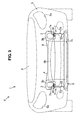
- the bumper face is formed in a curved shape in a plan view so that a central or intermediate portion thereof is positioned foremost and both-side portions thereof extend rearwardly, and the laterally-extending member is formed so that both-side end portions thereof are positioned above a central or intermediate portion thereof.
- the bumper face can be formed in the curved shape so that lower portions of both-side ends of the bumper face are positioned rearwardly from it central or intermediate portion, so that the design flexibility of the vehicle front portion can be increased.
- the location of the laterally-extending member can be lower, the sweeping-away function of the pedestrian's leg part can be obtained securely and thereby the pedestrian can be put on the engine hood properly.
- both-side ends of the laterally-extending member are positioned right below the pair of front side frames.
- the laterally-extending member is formed in a curved shape in an elevation view so that a central or intermediate portion thereof is positioned lowermost and the both-side portions thereof extend upwardly gradually toward both-side ends thereof.
- the laterally-extending member can be properly short, so that the vehicle can be properly light.
- the laterally-extending member curves smoothly, when the leg part of the pedestrian contacts the laterally-extending member, the pedestrian can be properly guided onto the center of the engine hood. Accordingly, it can be effectively prevented that the pedestrian hits against the bumper reinforcement directly at the outside portion of the front portion of the vehicle.
- the laterally-extending member has a standing-up portion which extends upwardly at a transition portion thereof which is located from the central or intermediate portion thereof to the both-side end portions thereof.
- a space where the bumper face can curve is formed on the outside of the standing-up portion, so that a lower portion of the bumper face can be formed in a curved shape in the plan view so that its both-side portions are located rearwardly compared to its central or intermediate portion. Accordingly, the design flexibility can be increased.
- the front body structure of a vehicle further comprises an undercover which is positioned below the laterally-extending member and covers a lower face of the vehicle, wherein the undercover comprises a support portion to support the laterally-extending member at a front end of a central or intermediate portion thereof.
- a longitudinal direction of a vehicle will be referred to as a "longitudinal direction” and a lateral direction of the vehicle will be referred to as a "lateral direction” simply.
- a front body 1 of a vehicle V comprises an engine hood 2 which at least partly covers over an engine room E, a pair of front side frames 3 which substantially extends in a vehicle longitudinal direction, a bumper reinforcement 4 which substantially extends in a vehicle width direction, a bumper face 5 which at least partly forms an outer surface of the front body 1, a leg-part sweeping-away member 6 (i.e., a laterally-extending member) which substantially extends in the vehicle width direction, a support member 7 which supports the member 6 at the front side frames 3, a radiator 8 (heat exchanger) which conducts a heat exchange between a coolant of an engine (not illustrated) and traveling air, and so on.
- a radiator 8 heat exchanger
- An engine-hood reinforcement 2a is arranged at or near a front end portion of the engine hood 2 so as to substantially extend in the vehicle width direction along an contour of the front end portion of the engine hood 2.
- the engine-hood reinforcement 2a forms a closed-cross section portion with the engine hood 2.
- the pair of front side frames 3 is disposed in front of a dash panel (not illustrated) which partitions a front end portion of a vehicle compartment so as to substantially extend in the vehicle longitudinal direction at both sides of the engine room E.
- the front side frames 3 extend substantially horizontally from a front position to a rear position of the vehicle V, a mid-way or intermediate portion of a rear end of which is joined to a vertical wall portion of the dash panel.
- the both-side front side frames particularly have substantially the same structure, so only the right-side front side frame 3 will be mainly described.
- the front side frame 3 is comprised of an outer panel on the outside and an inner panel on the inside, and these panels from a substantially-rectangular closed-cross section portion of the front side frame 3. Further, the front side frame 3 has plural beads 3a which are formed at its outer and inner panels, respectively, so as to extend vertically or intersect the longitudinal direction of the front side frame 3. A bead depth and/or a vertical length and/or an inclination thereof with respect to the longitudinal direction of the front side frame 3 of each bead 3a are set so that the front side frame 3 can be bent in a specified (predetermined or predeterminable) direction at a vehicle frontal collision.
- a flange 3b for attaching a crush can 9 via a shroud panel (not illustrated) is provided at or near a front end portion of the front side frame 3.
- the crush can 9, which particularly is of a square cylindrical shape, has one or more, e.g. two ring grooves 9a which are formed on its surface so as to extend perpendicularly to the vehicle longitudinal direction and/or be concaved toward the inside, respectively.
- the crush can 9 is fixed to the flange 3b via bolts at its rear end.
- the bumper reinforcement 4 is coupled to the front end portion of the crush can 9.
- the bumper reinforcement 4 has a substantially closed cross section which extends in the vehicle width direction.
- the front end portion of the crush can 9 is at least partly inserted into the inside of the closed cross section of the bumper reinforcement 4. Accordingly, the bumper reinforcement 4 has a U-shaped cross section at its specified portion for accepting the crush can 9.
- An impact absorbing member 10 which particularly is made from foaming synthetic resin, is arranged in front of the bumper reinforcement 4 over a whole area of the width of the bumper face 5.
- the impact absorbing member 10 absorbs the collision energy through its compressive deformation which is caused by the collision load inputted thereto via the bumper face 5 at the vehicle collision, and this member 10 has a proper size and/or shape for providing a desired energy absorption function.
- the impact absorbing member 10 may be made of a synthetic-resin made structure having plural ribs alternatively.
- the bumper face 5 comprises openings 5a for a pair of (particularly retractable) headlights, at least one traveling-air induction opening 5b (which particularly is substantially formed at a central or intermediate area thereof in the vehicle width direction) to induct the traveling air into the vehicle room E, a traveling-air induction opening 5c (which particularly is formed at a position below the traveling-air induction opening 5b), and so on.
- a pair of front fenders 11 which is substantially continuous from the bumper face 5 and forms an outer surface of a side portion of the vehicle is provided at both-side rear end portions of the bumper face 5.
- a shroud upper 12 which supports an upper portion of the radiator 8
- a shroud lower 13 which supports a lower portion of the radiator 8
- a pair of shroud sides (not illustrated) which interconnects the both-side end portions of the shroud upper 12 and both-side end portions of the shroud lower 13.
- These shroud upper 11, shroud lower 13 and pair of shroud sides are substantially arranged so as to slant forwardly, and these members particularly are of a rectangular frame shape having an opening at a central area thereof. This opening formed with these members is positioned so as to face to the above-described traveling-air induction openings 5b, 5c of the bumper face 5.
- the radiator 8 slants so that an upper side thereof is positioned forwardly in the vehicle longitudinal direction for a low engine-hood layout of the vehicle.
- the radiator 8 and a fan 14 for the radiator 8 are disposed between the shroud upper 12 and the shroud lower 13.
- the shroud upper 12 has a bracket (not illustrated) to support the upper portion of the radiator 8 which is attached thereto particularly with bolts.
- the shroud lower 13 has a bracket (not illustrated) to support the lower portion of the radiator 8.
- the radiator 8 cools the coolant (cooling water) of the engine with the traveling air inducted through the induction opening 5b and so on
- the (particularly synthetic-resin made) leg-part sweeping-away member 6 (laterally-extending member) is substantially provided in front of and/or below the bumper reinforcement 4, that is, below the impact absorbing member 10 and/or behind the traveling-air induction opening 5c which substantially corresponds to the height of a pedestrian's leg part so that its front end is positioned forwardly from the bumper reinforcement 4.
- the leg-part sweeping-away member 6 is comprised of an upper face portion 6a, a lower face portion 6b, a front face portion 6c, a rear face portion 6d, and so on, and has a substantially closed-cross section portion which substantially extends in the vehicle width direction.
- a projection 6e which substantially projects forwardly and substantially extends in the vehicle width direction is formed at or near a lower portion of the front face portion 6c.
- Both-side end portions of the leg-part sweeping-away member 6 are attached to the both-side support members 7 particularly by bolts 15.
- the leg-part sweeping-away member 6 may be formed in a solid structure in place of the above-described hollow structure.
- FIG. 1 an illustration of the leg-part sweeping-away member 6 is omitted because it is located almost at the same position as the impact absorbing member 10.
- the (particularly steel-plate made) support member 7 comprises an attachment portion 7a to attach the support member 7 to the crush can 9, a support body portion 7b, an impact transmission portion 7c which transmits the impact load to the support body portion 7b and attaches the leg-part sweeping-away member 6, and the like.
- the both-side support members 7 are fixed to respective lower end faces of the both-side crush cans 9 particularly with bolts 16. These support members 7 have substantially the same structure, so the right-side support member 7 will be described.
- the attachment portion 7a includes, as shown in FIG. 5 , a pair of bolt holes 30 which are for the bolts 16, one or more (e.g. two-row) beads 31 (weak portions) which are formed substantially facing to the above-described grooves 9a so as to extend at an angle different from 0° or 180°, preferably substantially perpendicularly to the vehicle longitudinal direction and/or be concaved toward an opposite side to the grooves 9a, respectively, and so on.
- a pair of bolt holes 30 which are for the bolts 16, one or more (e.g. two-row) beads 31 (weak portions) which are formed substantially facing to the above-described grooves 9a so as to extend at an angle different from 0° or 180°, preferably substantially perpendicularly to the vehicle longitudinal direction and/or be concaved toward an opposite side to the grooves 9a, respectively, and so on.
- the attachment portion 7a is substantially arranged in parallel to a face perpendicular to the vehicle vertical direction, and each bead 31 is arranged at an angle different from 0° or 180°, preferably substantially perpendicular to the vehicle longitudinal direction.
- the attachment portion 7a fixed to the lower end face of the crush can 9 with the bolts 16 can be crushed substantially in the vehicle longitudinal direction through the crush deformation of the beads 31. Accordingly, the attachment portion 7a can support the leg-part sweeping-away member 6 at the front side frame 3 without hindering the collision-energy absorption by the crush can 9.
- the support body portion 7b is formed so as to bend from an outside end portion of the attachment portion 7a and substantially extend downwardly, and includes one or more (e.g. two-row) beads 32 (impact absorption portion) which are formed so as to be concaved toward the inside of the vehicle and/or extend at an angle different from 0° or 180° to the vehicle longitudinal direction, preferably substantially vertically and so on.
- the front bead 32 extends substantially downwardly continuously from an outside end portion of the front bead 31, and particularly has a curved portion 32a which substantially curves forwardly at a lower portion of the support body portion 7b and extends up to a front end portion of the support body portion 7b.
- the rear bead 32 substantially extends downwardly continuously from an outside end portion of the rear bead 31, and has a curved portion 32a which substantially curves forwardly at a lower portion of the support body portion 7b and extends to a midway or intermediate position of the support body portion 7b substantially in the vehicle longitudinal direction.
- Upper portions of the front bead 32 and the rear bead 32 extend vertically almost in parallel to each other, and lower portions of these are formed substantially at the same height position.
- a bead depth and/or an extension or a vertical length of each bead 32 are set so as to absorb the impact load which is greater than the collision energy necessary to put the pedestrian on the engine hood 2 when the vehicle collides with the pedestrian. Thereby, the impact load acting on the pedestrian at the collision can be as small as possible, and the pedestrian can be put on the engine hood 2 effectively.
- the impact transmission portion 7c is formed so as to substantially curve forwardly from a lower end portion of the support body portion 7b.
- the impact transmission portion 7c particularly includes an attachment portion 33 which is formed so as to bend inwardly from its front end portion for attaching the leg-part sweeping-away member 6, one or more (e.g. a pair of) bolt holes 34 which is formed at the attachment portion 33, and so on.
- the leg-part sweeping-away member 6 which is fixed to the front surface of the attachment portion 33 is fixed to the support member 7 by the one or more bolts 15 inserted through the respective bolt holes 34.
- a (particularly synthetic-resin made) undercover 17 is provided below a front portion of the engine room E.
- the undercover 17 substantially extends from a lower end portion of the bumper face 5 to a position below the shroud lower 13 supporting the lower portion of the radiator 8.
- An attachment bracket (not illustrated) which is provided at the leg-part sweeping-away member 6 at its central position is connected to a front end portion of the undercover 17.
- the impact load inputted to the front end portion of the front side frame 3 acts on the plural beads 3a, which causes a start of bending deformation of the beads 3a.
- the beads 3a since the beads 3a particularly are formed in a concave shape, the modulus of section of this bead's part of the front side frame 3 is smaller than that of another part of that which is located in front or back of this bead's part.
- the beads 3a tend to substantially bend outwardly in the vehicle width direction easily. Accordingly, the collision energy from the vehicle frontal collision is absorbed.
- the (two-row) beads 31 are formed substantially corresponding to the grooves 9a, so that the beads 31 are crushed in the vehicle longitudinal direction according to the crush deformation of the grooves 9a. Thereby, the absorption of the collision energy by the crush can 9 in the initial stage of the collision is not hindered.
- the control of sweeping away the leg part of the pedestrian by the leg-part sweeping-away member 6 will be described.
- the leg-part sweeping-away member 6 is substantially disposed below the impact absorbing member 10 and/or behind the traveling-air induction opening 5c which substantially corresponds to the height of the pedestrian's leg part, the projection 6e hits against the leg part of the pedestrian via the bumper face 5.
- the impact load inputted to the projection 6e is absorbed through the crush deformation of the upper face portion 6a and the lower face portion 6b.
- Part of the impact load which has not absorbed through the crush deformation of the above-described portions 6a, 6b is or may be transmitted from the attachment portion 33 to the impact transmission portion 7c. Since the impact transmission portion 7c particularly is formed in the flat-plate shape by curving forwardly from the lower end portion of the support body portion 7b, the longitudinal-direction impact load is transmitted to the support body portion 7b with little damping.
- the impact load inputted to the support body portion 7b is absorbed by the deformation of the (two-row) beads 32 particularly extending at an angle different from 0° or 180° to the vehicle longitudinal direction, preferably substantially vertically.
- the crush deformation of a front part of the front bead 32 absorbs the impact load.
- a crush area A of the front bead 32 enlarges rearwardly and upwardly. Part of the impact load not absorbed through the crush deformation of the front bead 32 is or may be absorbed by the crush deformation of the rear bead 32.
- the both beads 32 have their crush deformation. While in case the impact transmission portion 7c substantially moves downwardly, the both beads 32 have their extension deformation. Thus, these deformations of the beads 32 at least partly absorb the impact load.
- the pedestrian's leg part is swept away by the leg-part sweeping-away member 6 so that the pedestrian can be put on the engine hood 2 effectively before the upper-half body of the pedestrian hits against the bumper reinforcement 4.
- the impact load which is greater than the collision energy which may be necessary to have the pedestrian put on the engine hood 2 is absorbed by the crush deformation of the beads 32, the impact load which may act on the pedestrian cane be lower.
- this front body structure comprises the pair of front side frames 3 substantially extending in the vehicle longitudinal direction below the engine hood 2, the bumper reinforcement 4 attached to the respective front end portions of the front side frames 3 and substantially extending in the vehicle width direction, the bumper face 5 forming the outer surface of the front end portion of the vehicle, the leg-part sweeping-away member 6 substantially provided below the bumper reinforcement 4 and substantially extending in the vehicle width direction, the front end of which is positioned in front of the bumper reinforcement 4, and the support member 7 supporting the leg-part sweeping-away member 6 at the front side frames 3, it can be prevented that the pedestrian is caught under the vehicle at the collision of the vehicle V with the pedestrian.
- the support member 7 comprises the beads 32 which at least partly absorb the impact load inputted to the leg-part sweeping-away member 6 in the vehicle longitudinal direction, it may be unnecessary that leg-part sweeping-away member 6 have any particular impact-absorbing function and thereby the longitudinal length of the leg-part sweeping-away member 6 can be properly short, so that the vehicle weight can be properly light.
- the short leg-part sweeping-away member 6 particularly is provided, the flexibility of attachment of the support member 7 to the front side frame 3 can be increased.
- the rigidity of the support member 7 can be decreased, so that the support member 7 can be attached to the front side frame 3 properly without hindering the deformation mode control of the front side frame 3 at the collision.
- the leg-part sweeping-away member 6 comprises the upper face portion 6a, lower face portion 6b, front face portion 6c, rear face portion 6d, projection 6e and so on, and particularly has the structure with the substantially closed-cross section extending in the vehicle width direction, the deformation of the support member 7 can be promoted with the transmission of the impact load to the support member 7. Further, adjustment of the impact absorption can be facilitated by particularly setting the support member 7 with the above-described promotion of the deformation of the support member 7. Accordingly, the short and small-sized leg-part sweeping-away member 6 can be provided as well as the proper absorption of the impact load longitudinally inputted to the leg-part sweeping-away member 6 by the support member 7.
- the support member 7 particularly comprises the attachment portion 7a to attach the support member 7 to the front side frame 3, the support body portion 7b comprising the beads 32, and the impact transmission portion 7c to transmit the impact load to the support body portion 7b and support the leg-part sweeping-away member 6, and the impact transmission portion 7c substantially extends forwardly from the lower end portion of the support body portion 7c, the longitudinal length of the leg-part sweeping-away member 6 can be properly short, thereby providing the light-weight vehicle.
- the pair of front side frames 3 particularly has the crush can 9 at the front end thereof, which absorbs the impact load inputted to the bumper reinforcement 4 in the vehicle longitudinal direction through its deformation substantially in the longitudinal direction, and the attachment portion 7a is attached to the lower end face of the crush can 9 and particularly comprises the one or more beads 31 to allow the deformation of the crush can 9, the leg-part sweeping-away member 6 can be supported at the front side of the vehicle, without hindering the crush deformation of the grooves 9a of the crush can 9. Consequently, the longitudinal length of the leg-part sweeping-away member 6 can be properly short.
- FIG. 9 A front body structure of a vehicle according to a second embodiment will be described referring to FIG. 9 .
- the similar or same components as the first embodiment are denoted by the same reference characters, descriptions of which are omitted here.
- a leg-part sweeping-away member 6A which is made of a steel plate, has the structure with the closed cross section substantially extending in the vehicle width direction, and the longitudinal-direction rigidity of the leg-part sweeping-away member 6A particularly is greater than that of the support member 7.
- the leg-part sweeping-away member 6A comprises the upper face portion 6a, lower face portion 6b, front face portion 6c, rear face portion 6d, projection 6e which substantially projects forwardly from the lower portion of the front face portion 6c, and so on. Both-side end portions of the leg-part sweeping-away member 6A are attached to the both-side support members 7 with the bolts 15.
- the leg-part sweeping-away member 6A particularly has the greater longitudinal-direction rigidity than the support member 7, the impact energy can be absorbed only by the support member 7.
- the adjustment of the impact absorption can be facilitated only by setting the beads 32 and the proper rigidity with selection of material and the like of the support member 7.
- the longitudinal length of the leg-part sweeping-away member 6A can be further shortened with the high rigidity of the leg-part sweeping-away member 6A, thereby achieving the light weight of the vehicle.
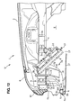
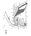
- FIGS. 10 through 12 A front body structure of a vehicle according to a third embodiment will be described referring to FIGS. 10 through 12 .
- FIGS. 10 through 12 A front body structure of a vehicle according to a third embodiment will be described referring to FIGS. 10 through 12 .
- the similar or same components as the first embodiment are denoted by the same reference characters, descriptions of which are omitted here.
- the radiator 8 and the fan 14 for the radiator 8 are supported at the shroud upper 12 and the shroud lower 13.
- the radiator 8 arranged in the slant state is disposed so as to substantially face or being oriented to the traveling-air induction openings 5b, 5c of the bumper face 5.
- a (particularly steel-plate made) support member 7A comprises the attachment portion 7a to attach the support member 7A to the lower end face of the crush can 9, support body portion 7b, impact transmission portion 7c which transmits the impact load to the support body portion 7b and attaches the leg-part sweeping-away member 6, and so on.
- the both-side support members 7A have substantially the same structure, so the right-side support member 7A will be described.
- the support body portion 7b is formed so as to bend from the outside end portion of the attachment portion 7a and substantially extend downwardly, and includes the one or more (e.g. two-row) beads 32 which are formed so as to be concaved toward the inside of the vehicle and/or extend at an angle different from 0° or 180° to the vehicle longitudinal direction, preferably substantially vertically, a plate-shaped projecting portion 35 which projects in back of the beads 32, and so on.
- the front bead 32 substantially curves forwardly at the lower portion of the support body portion 7b and substantially extends up to the front end portion of the support body portion 7b.
- the rear bead 32 substantially curves forwardly at the lower portion of the support body portion 7b and substantially extends to a front portion of the support body portion 7b.
- Upper portions of the front bead 32 and the rear bead 32 substantially extend vertically almost in parallel to each other.
- the projection portion 35 substantially extends from a position in back of the rear bead 32 to a position above and beside the radiator 8 provided in back of the flange 3b, and it is arranged below the front side frame 3 substantially in parallel to the front side frame 3.
- a rear end portion of the projection portion 35 curves forwardly.
- the longitudinal width of a lower part of the projection portion 35 is narrower than that of an upper part of that.
- the projection portion 35 has an attachment portion 36 to attach the support member 7A to the lower end face of the front side frame 3 at its upper end portion.
- the both-side support members 7A are fixed to the respective crush cans 9 and the respective lower end faces of the front side frames 3 with the bolts 16, respectively.
- the impact transmission portion 7c substantially curves forwardly from the lower end portion of the support body portion 7b.
- One or more, particularly a pair of traveling-air guide portions 18 particularly is arranged between the traveling-air induction openings 5b, 5c and the radiator 8 so as to guide the traveling air passing through the induction openings 5b, 5c to the radiator 8.
- the traveling-air guide portion 18, which particularly is made of a synthetic-resin plate, is positioned below the front side frame 3.
- the traveling-air guide portion 18 is connected to the projection portion 35 e.g. with bolts at or near its front side end, and it is disposed in a slant state so that its rear end approaches toward the center in the vehicle width direction.
- the left-side traveling-air guide portion 18 is configured to be similar to the right-side traveling-air guide portion 18.
- the traveling air passing through the induction openings 5b, 5c can be effectively guided towards or to the radiator 8, so that the cooling function of the radiator 8 can be improved. Further, since the traveling air which passes through on the outside of the radiator 8, that is, below the front side frame 3 is guided toward the center of the vehicle, the cooling function of the radiator 8 can be further improved.
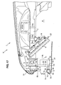
- FIGS. 13 through 15 A front body structure of a vehicle according to a fourth embodiment will be described referring to FIGS. 13 through 15 .
- the similar or same components as the first embodiment are denoted by the same reference characters, descriptions of which are omitted here.
- a (particularly steel-plate made) support member 7B comprises a front support portion 7d, a rear support portion 7e, a middle or intermediate portion 7f which is formed between the front and rear support portions 7d, 7e, and so on.
- the both-side support members 7B are fixed to the lower end faces of the both-side crush cans 9 with the bolts 16.
- the both-side support members 7B have substantially the same structure, so the right-side support member 7B will be described.
- the front support portion 7d comprises an attachment portion 37 which attaches the support member 7B to the crush can 9, a connection portion 38 which connects the leg-part sweeping-away member 6 particularly with bolts, a front body portion 39 which interconnects the attachment portion 37 and the connection portion 38, and so on.
- the attachment portion 37 is fixed to an outside position of the lower end face of the crush can 9 with the bolts 16.
- the front body portion 39 substantially bends downwardly from an outside end of the attachment portion 37.
- the connection portion 38 substantially bends inwardly from a front end of a lower end portion of the front body portion 39.
- the rear support portion 7e comprises an attachment portion 40 which attaches the support member 7B to the crush can 9, a rear body portion 41 which is positioned below the attachment portion 40, and so on.
- the attachment portion 40 is fixed to an inside position of the lower end face of the crush can 9.
- the rear body portion 41 substantially bends downwardly from an inside end of the attachment portion 40.
- the middle portion 7f is positioned right below the front side frame and extends so as to slant obliquely rearwardly and inwardly.
- the middle or intermediate portion 7f is a portion corresponding to a border with the front support member 7d, and comprises a substantially V-shaped bending portion 42 (impact absorption portion) which substantially faces to the vehicle inside and substantially extends vertically, a substantially V-shaped bending portion 43 (impact absorption portion) which is a portion corresponding to a border with the rear support portion 7e and substantially faces to the vehicle inside and substantially extends vertically, an upper opening 44 which is formed at an upper end portion of the middle or intermediate portion 7f between the attachment portion 37 and the attachment portion 40, and so on.
- the middle or intermediate portion 7f crushes according to the crush deformation of the crash can 9 from the collision of the vehicle V so that the both V-shaped bending portions 42, 43 bend. Thereby, the crush deformation of the crush can 9 is not hindered by the support member 7B. Accordingly, the support member 7B can support the leg-part sweeping-away member 6 at the front side frame 3 properly, without hindering the impact-energy absorption of the crush can 9.
- the leg-part sweeping-away member 6 particularly is disposed below the impact absorbing member 10 and behind the traveling-air induction opening 5c which corresponds to the height of the pedestrian's leg part, the projection 6e hits against the leg part of the pedestrian via the bumper face 5.
- the impact load is inputted from the connection portion 38 to the front support portion 7d.
- the V-shaped bending portion 42 bends so that the front support portion 7d moves outwardly, thereby absorbing part of the impact load.
- the rest of the impact load which has not been absorbed by the deformation of the V-shaped bending portion 42 and the front support portion 7d is absorbed by the V-shaped bending portion 42 bending so that the rear support portion 7e substantially moves inwardly.
- the impact load which is greater than the necessary impact energy for putting the pedestrian on the engine hood 2 is absorbed by the bending deformation of the V-shaped bending portions 42, 43, so that the impact load acting on the pedestrian can be properly small.
- the middle or intermediate portion 7f particularly slants obliquely rearwadly and inwardly, the traveling air passing through the traveling-air induction openings 5b, 5c can be guided to the radiator 8, so that the cooling function of the radiator 8 can be further improved.
- FIGS. 16 through 18 A front body structure of a vehicle according to a fifth embodiment will be described referring to FIGS. 16 through 18 .
- the similar or same components as the fourth embodiment are denoted by the same reference characters, descriptions of which are omitted here.
- a (particularly steel-plate made) support member 7C comprises the front support portion 7d, the rear support portion 7e, the middle or intermediate portion 7f which is formed between the front and rear support portions 7d, 7e, and so on.
- the both-side support members 7C are fixed to the lower end faces of the both-side crush cans 9 with the bolts 16.
- the middle or intermediate portion 7f is positioned right below the lower end face of the crush can 9 and extends so as to slant obliquely rearwardly and inwardly.
- the middle or intermediate portion 7f particularly comprises the V-shaped bending portion 42, the V-shaped bending portion 43, the upper opening 44, a central opening 45 which is formed below the upper opening 44, and so on.
- the central opening 45 has a size which can absorb, along with the V-shaped bending portions 42, 43, the impact load greater than the necessary collision energy for putting the pedestrian on the engine hood 2 at the collision with the pedestrian.
- the support member 7C can support the leg-part sweeping-away member 6 at the front side frame 3 properly, without hindering the impact-energy absorption of the crush can 9. Further, since the impact load is absorbed by the bending deformation of the V-shaped bending portions 42, 43, the impact load acting on the pedestrian can be made small. Moreover, the light weight of the support member 7C can be achieved by the central opening 45, so that the vehicle weight can be decreased.
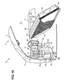
- FIGS. 19 and 20 A front body structure of a vehicle according to a sixth embodiment will be described referring to FIGS. 19 and 20 .
- FIGS. 19 and 20 A front body structure of a vehicle according to a sixth embodiment will be described referring to FIGS. 19 and 20 .
- the similar or same components as the first embodiment are denoted by the same reference characters, descriptions of which are omitted here.
- the front body structure of the vehicle V comprises the engine hood 2, the pair of front side frames 3, the bumper reinforcement 4, the bumper face 5, a leg-part sweeping-away member 6B (laterally-extending member), a support member 7D which supports the leg-part sweeping-away member 6B at the front side frames 3, the radiator 8, an intercooler 19 (as a second heat exchanger added to the radiator 8) which cools an intake air heated through compression, and so on.
- the leg-part sweeping-away member 6B particularly is disposed below the impact absorbing member 10 and/or behind the traveling-air induction opening 5c which substantially corresponds to the height of the pedestrian's leg part.
- the longitudinal rigidity of the leg-part sweeping-away member 6B particularly is greater than that of the support member 7D.
- the leg-part sweeping-away member 6B has a U-shaped cross section, and is attached to the both-side support members 7D with the bolts 15.
- the steel-plate made support member 7D comprises the attachment portion 7a, support body portion 7d, impact transmission portion 7c, and so on.
- the both-side support members 7D are fixed to the lower end faces of the both-side crush cans 9 with the bolts 16.
- the attachment portion 7a includes the (two-row) beads 31 which are formed facing to the two grooves 9a so as to extend at an angle different from 0° or 180°, preferably substantially perpendicularly to the vehicle longitudinal direction and be concaved toward the opposite side to the grooves 9a, respectively, and so on.
- the attachment portion 7a particularly is arranged substantially in parallel to a face perpendicular to the vehicle vertical direction, and each bead 31 is arranged in perpendicular to the vehicle longitudinal direction.
- the support body portion 7b is formed so as to bend perpendicularly from the outside end portion of the attachment portion 7a, and/or includes the (two-row) beads 32 which are formed so as to be concaved toward the inside of the vehicle and extend vertically, an opening 46 (an exhaust port), and so on.
- the front bead 32 substantially extends downwardly continuously from the outside end portion of the front bead 31 and then substantially curves forwardly at the lower portion of the support body portion 7b and substantially extends up to the front end portion of the support body portion 7b.
- the rear bead 32 substantially extends downwardly continuously from the outside end portion of the rear bead 31 and substantially curves forwardly at the lower portion of the support body portion 7b.
- the opening 46 particularly is formed in a rectangular shape and positioned at a portion between the front and rear beads 32 so as to penetrate the support body portion 7b.
- the intercooler 19 is arranged near the right end portion of the leg-part sweeping-away member 6B, and fixed via an attachment bracket (not illustrated).
- a synthetic-resin made duct 21 (a guide flow passage) which at least partly guides the traveling air passing through the intercooler 19 to a wheel house 20.
- the traveling air which has been heat-exchanged with the intercooler 19 is guided through the duct 21 to the wheel house 20, and then discharged to the outside of the vehicle V.
- the traveling air before the heat exchange with the radiator 8 is supplied to the intercooler 19, and also it is prevented to guide the traveling air heated through the heat exchange with the intercooler 19 is supplied to the radiator 8, so that the proper cooling function of the both heat exchangers 8, 19 can be kept.
- the duct 21 is made of synthetic resin, it may not provide any improper influence to the crush deformation of the support member 7D.
- the present embodiment can perform the similar operation and effects to the first embodiment basically. Further, since the longitudinal rigidity of the leg-part sweeping-away member 6B particularly is greater than that of the support member 7D, the adjustment of the impact absorption can be conducted easily by setting the beads 32 of the support member 7D and the like. Moreover, the proper cooling function of the radiator 8 and the intercooler 19 can be kept.
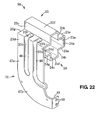
- FIGS. 21 and 22 A front body structure of a vehicle according to a seventh embodiment will be described referring to FIGS. 21 and 22 .
- FIGS. 21 and 22 A front body structure of a vehicle according to a seventh embodiment will be described referring to FIGS. 21 and 22 .
- the similar or same components as the first embodiment are denoted by the same reference characters, descriptions of which are omitted here.
- a pair of crush cans 9A is attached to the flanges 3b of the front side frames 3.
- a support member 7E which supports the leg-part sweeping-away member 6 is integrally or unitarily formed with each crush can 9A.
- the both crush cans 9A have a similar structure, so the right-side crush can 9A will be described.
- the crush can 9A comprises an upper panel 23 and a lower panel 24, which form together a (particularly substantially cross-shaped) closed cross section which substantially extends in the vehicle, longitudinal direction.
- the upper panel 23 comprises a vertical face portion 23a located on the vehicle inside, a horizontal face portion 23e which connects an upper end portion of the vertical face portion 23a and a lower end portion of a vertical face portion 23b, the vertical face portion 23b which connects an outside end portion of the horizontal face portion 23e and an inside end portion of a horizontal face portion 23f, the horizontal face portion 23f which connects an upper end portion of the vertical face portion 23b and an upper end portion of a vertical face portion 23c, the vertical face portion 23c which connects an outside end portion of the horizontal face portion 23f and an inside end portion of a horizontal face portion 23g, the horizontal face portion 23g which connects a lower end portion of the vertical face portion 23c and an upper end portion of a vertical face portion 23d, the vertical face portion 23d which substantially extends downwardly from an upper end portion of the
- One or more (particularly two-row) beads 23h are formed on the horizontal face portion 23g so as to extend at an angle different from 0° or 180°, preferably substantially perpendicularly to the vehicle longitudinal direction and be concaved toward the inside of the crush can 9A.
- On the vertical face portion 23d are formed two-row beads 23i which are continuous from the above-described beads 23h and concaved inwardly and substantially extend downwardly, respectively.
- the lower panel 24 comprises a vertical face portion 24a located on the vehicle inside, a horizontal face portion 24e which connects a lower end portion of the vertical face portion 24a and an upper end portion of a vertical face portion 24b, the vertical face portion 24b which connects an outside end portion of the horizontal face portion 24e and an inside end portion of a horizontal face portion 24f, the horizontal face portion 24f which connects a lower end portion of the vertical face portion 24b and a lower end portion of a vertical face portion 24c, the vertical face portion 24c which connects an outside end portion of the horizontal face portion 24f and an inside end portion of a horizontal face portion 24g, the horizontal face portion 24g which connects an upper end portion of the vertical face portion 24c and a lower end portion of a vertical face portion 24d, the vertical face portion 24d which substantially extends downwardly from an upper end portion of the horizontal face portion 24g, and so on.
- the support member 7E substantially extends downwardly from a lower end of the vertical face portion 23d so as to be informed integrally or unitarily with the crush can 9A.
- the support member 7E comprises a support body portion 47a and an impact transmission portion 47b.
- One or more (e.g. two-row) beads 48 which are concaved inwardly and substantially extend vertically are formed at the support body portion 47a.
- the front bead 48 substantially extends downwardly continuously from a lower end of the front bead 23i, and substantially curves forwardly at a lower portion of the support body portion 47a and substantially extends up to a front end portion of the support body portion 47a.
- the rear bead 48 substantially extends downwardly continuously from a lower end portion of the rear bead 23i, and substantially curves forwardly at a lower portion of the support body portion 47a.
- a bead depth and a vertical length of each bead 48 are set so as to absorb the impact load which is greater than the collision energy necessary to put the pedestrian on the engine hood 2 when the vehicle collides with the pedestrian.
- the impact transmission portion 47b is formed so as to substantially curve forwardly from a lower end portion of the support body portion 47a.
- the impact transmission portion 47b includes an attachment portion 49 which is formed so as to substantially bend inwardly from its front end portion for attaching the leg-part sweeping-away member 6, a pair of bolt holes 50 which is formed at the attachment portion 49, and so on.
- the leg-part sweeping-away member 6 which is fixed to the front surface of the attachment portion 49 is fixed to the support member 7E particularly by bolts (not illustrated) inserted through the bolt holes 50.
- the present embodiment can perform the similar effects to the first embodiment basically. Further, since the vertical face portion 23d of the crush can 9A substantially extends downwardly and/or is formed integrally or unitarily with the support member 7E to support the leg-part sweeping-away member 6, it may be unnecessary to provide any particular attachment portion for the support member 7E, so that the reduction of the vehicle weight and the easy control of crush deformation of the crush can 9A can be achieved.
- FIG. 23 a modified embodiment of the above-described crush can 9A which is formed integrally or unitarily with the support member supporting the leg-part sweeping-away member 6 will be described referring to FIG. 23 .
- the similar or same components as the seventh embodiment are denoted by the same reference characters, descriptions of which are omitted here.
- a pair of crush canes has the similar structure, so the right-side one will be described.
- a crush can 9B comprises an outer panel 25 and an inner panel 26, which form together a (particularly substantially cross-shaped) closed cross section which substantially extends in the vehicle longitudinal direction.
- the upper panel 25 comprises a horizontal face portion 25a, a vertical face portion 25e, a horizontal face portion 25b, a vertical face portion 25f, a horizontal face portion 25c, a vertical face portion 25g, a horizontal face portion 25d, and so on.
- the inner panel 26 comprises a horizontal face portion 26a, a vertical face portion 26e, a horizontal face portion 26b, a vertical face portion 26f, a horizontal face portion 26c, a vertical face portion 26g, a horizontal face portion 26d, and so on.
- the longitudinally-extending closed cross section of a crush can 7F particularly is formed by welding the horizontal face portion 25a to the horizontal face portion 26e, and the horizontal face portion 25d to the horizontal face portion 26d.
- the support member 7F is formed integrally or unitarily with the outer panel 25 so as to bend from an inside end of the horizontal face portion 25d and substantially extend downwardly.
- the support member 7F comprises a support body portion 47a and an impact transmission portion 47b.
- Two-row beads 48 which are concaved inwardly and substantially extend vertically area formed at the support body portion 47a.
- any bead which substantially extends perpendicularly to the vehicle longitudinal direction may be formed at the face portions 25a-25g, 26a-26b of the crush can 9B at need.
- the vertical face portion 25d of the crush can 9B is formed integrally or unitarily with the support member 7F to support the leg-part sweeping-away member 6, it may be unnecessary to provide any particular attachment portion for the support member 7F, so that the reduction of the vehicle weight and the easy control of crush deformation of the crush can 9B can be achieved. Further, since the attachment portion of the support member 7F to the leg-part sweeping-away member 6 particularly can be arranged on the inside in the vehicle width direction, the design flexibility of the vehicle can be increased.
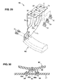
- FIGS. 24 and 30 A front body structure of a vehicle according to a ninth embodiment will be described referring to FIGS. 24 and 30 .
- the similar or same components as the first embodiment are denoted by the same reference characters, descriptions of which are omitted here.
- a leg-part sweeping-away member 6C as the laterally-extending member is formed so that its both-side end portions are positioned above its central portion.
- this leg-part sweeping-away member 6C is formed in a curved shape in the elevation view so that its central portion is positioned lowermost and its both-side portions substantially extend upwardly toward its both-side ends as apparently shown in FIG. 25 .
- the both-side ends of the leg-part sweeping-away member 6C are positioned right below the pair of front side frames 3.
- the bumper face 5 is formed in the curved shape in the plan view so that its central portion is positioned foremost and its both-side portions substantially extend rearwardly as shown in FIG. 24 , like the first embodiment.
- a steel-plate made support member 7G has a structure which is substantially similar to the support member 7 of the above-described first embodiment. That is, this support member 7G comprises the attachment portion 7a to attach the support member 7G to the crush can 9, the support body portion 7b, the impact transmission portion 7c which transmits the impact load to the support body portion 7b and attaches the leg-part sweeping-away member 6C, and so on.
- the attachment portion 7a includes, as shown in FIG. 29 , one or more (e.g. three) bolt holes 60 which particularly are formed at a front portion, a middle or intermediate portion, and a rear portion for the bolts 16, respectively, the two-row beads 31, and so on.
- the support body portion 7b is formed so as to bend from the outside end portion of the attachment portion 7a and extend downwardly, and includes one or more (e.g. two-row) beads 22 (impact absorption portion) which are formed so as to be concaved toward the inside of the vehicle and extend at an angle different from 0° or 180° to the vehicle longitudinal direction, preferably substantially vertically and so on.
- the impact transmission portion 7c has a pair of bolt holes 63.
- the leg-part sweeping-away member 6C is fixed to the support member 7G by the one or more bolts 15 which are inserted into the respective bolt holes 63.
- the both-side ends of the leg-part sweeping-away member 6C are provided right below the outside ends of the crush cans 9.
- a support bracket 80 to support the central or intermediate portion of the leg-part sweeping-away member 6C at the vehicle central or intermediate position.
- This (particularly metal-made) support bracket 80 has a cross section which substantially is of a U shape.
- the support bracket 80 comprises a pair of connection portions 80a which is connected to the undercover 17, a connection portion 80b which is positioned between these portions 80a and connected to the central or intermediate portion of the leg-part sweeping-away member 6C, and so on.
- the support bracket 80 is fixed to the upper face of the undercover 17 e.g.
- leg-part sweeping-away member 6C is supported at the undercover 17 by bolts 95 via the connection portion 80b.
- the central or intermediate portion of the leg-part sweeping-away member 6C is supported firmly at the undercover 17, any move of the central portion of the leg-part sweeping-away member 6C which may be caused by a downward bending moment at vehicle collision with the pedestrian can be properly restrained.
- the leg part of the pedestrian can be securely swept away at a previously-set height position, so that pedestrian can be properly put on the engine hood 2.
- the leg-part sweeping-away member 6C particularly is formed in the curved shape in the elevation view so that its both-side end portions are positioned above its central portion, even in case the leg-part sweeping-away member 6C is located at a low height position, a space can be formed at the lower portion at the both sides.
- the bumper face 5 can be formed in the curved shape so that lower portions of both-side ends of the bumper face 5 are positioned rearwardly from its central portion, so that the design flexibility of the vehicle front portion can be increased.
- the both-side ends of the leg-part sweeping-away member 6C particularly are positioned right below the pair of front side frames 3, the sweeping-away function of the pedestrian's leg part can be performed in a wide range in the vehicle width direction between the pair of front side frames 3, so that the safety of the pedestrian at the collision with the vehicle can be secured.
- leg-part sweeping-away member 6C particularly is formed in the curved shape in the elevation view so that its central or intermediate portion is positioned lowermost and its both-side portions substantially extend upwardly toward its both-side ends, the leg-part sweeping-away member 6C can be properly short, so that the vehicle can be properly light. Further, when the leg part of the pedestrian contacts the leg-part sweeping-away member 6C, the pedestrian can be properly guided onto the center of the engine hood 2. Accordingly, it can be effectively prevented that the pedestrian hits against the bumper reinforcement 4 directly at the outside portion of the front portion of the vehicle.
- the front body structure of a vehicle particularly further comprises the undercover 17 which is positioned below the leg-part sweeping-away member 6C and covers the lower face of the vehicle, wherein the undercover 17 has the support bracket 80 to support the leg-part sweeping-away member 6C at the front end of its central portion, the downward moment which acts on the central or intermediate portion of the leg-part sweeping-away member 6C at the vehicle collision with the pedestrian can be supported by the undercover 17, so that the move of the leg-part sweeping-away member 6C can be restrained. Accordingly, the sweeping away of the leg part of the pedestrian can be conducted at the effective height position.
- FIGS. 31 and 32 A front body structure of a vehicle according to a tenth embodiment will be described referring to FIGS. 31 and 32 .
- the similar or same components as the ninth embodiment are denoted by the same reference characters, descriptions of which are omitted here.
- a leg-part sweeping-away member 6D (laterally-extending member) is provided in front of and below the bumper reinforcement 4, that is, below the impact absorbing member 10 and/or behind the traveling-air induction opening 5c which corresponds to the height of a pedestrian's leg part so that its front end is positioned forwardly from the bumper reinforcement 4.
- the leg-part sweeping-away member 6D which is made from synthetic resin, is substantially formed in a U shape in the elevation view so that its central or intermediate portion is concaved downwardly.
- the leg-part sweeping-away member 6D is comprised of a central portion 6f, outside end portions 6g which form both end portions thereof, standing-up portions 6h which are formed between the central portion 6f and the outside end portions 6g, and so on.
- the leg-part sweeping-away member 6D comprises, like the ninth embodiment, the upper face portion 6a, lower face portion 6b, front face portion 6c, rear face portion 6d, and so on, and has a solid structure which extends in the vehicle width direction.
- the above-described central portion 6f particularly extends substantially straightly over the width of the radiator 8 in the elevation view.
- the height position of the central portion 6f corresponds to a lower edge of the traveling-air induction opening 5c.
- the outside end portions 6g are formed so as to extend substantially straightly from the both-side ends of the leg-part sweeping-away member 6D toward the central or intermediate portion at a height position between the traveling-air induction openings 5b and 5c.
- the both standing-up portions 6h substantially extend upwardly at a transition portion from the both ends of the central portion 6f to the respective outside end portions 6g, upper ends of which are positioned below a lower edge of the traveling-air induction opening 5b.
- a space can be formed on the outside of the standing-up portions 6h.
- the space where the bumper face 5 can curve is formed on the outside of the standing-up portions 6h, so that the lower portion of the bumper face can be formed in the curved shape in the plan view so that its both-side portions particularly are located rearwardly compared to its central portion. Accordingly, the design flexibility can be increased.
- a modification of the crush can which is integrally or unitarily formed with the support member supporting the leg-part sweeping-away member will be described referring to FIG. 33 .
- the crush can 9 of the previous embodiments will be described, and the similar or same components as the first embodiment are denoted by the same reference characters, descriptions of which are omitted here.
- the both-side crush cans have the same structure, so the right-side crush can will be described.
- a crush can 9C of the present embodiment comprises an upper panel 66 and a lower panel 77, which particularly form together a substantially cross-shaped closed cross section which extends in the vehicle longitudinal direction.
- the upper panel 66 comprises a vertical face portion 66a located on the vehicle inside, a horizontal face portion 66b which connects an upper end portion of the vertical face portion 66a and a lower end portion of a vertical face portion 66c, the vertical face portion 66c which connects an outside end portion of the horizontal face portion 66b and an inside end portion of a horizontal face portion 66d, the horizontal face portion 66d which connects an upper end portion of the vertical face portion 66c and an upper end portion of a vertical face portion 66e, the vertical face portion 66e which connects an outside end portion of the horizontal face portion 66d and an inside end portion of a horizontal face portion 66f, the horizontal face portion 66f which connects a lower end portion of the vertical face portion 66e and an upper end portion of a
- One or more (e.g. two-row) beads 66h are formed on the horizontal face portion 66f so as to extend at an angle different from 0° or 180°, preferably substantially perpendicularly to the vehicle longitudinal direction and/or be concaved toward the inside of the crush can 9C.
- On the vertical face portion 66g are formed two-row beads 66i which are continuous from the above-described beads 66h and concaved inwardly and/or extend downwardly, respectively.
- the lower panel 77 comprises a vertical face portion 77a located on the vehicle inside, a horizontal face portion 77b which connects a lower end portion of the vertical face portion 77a and an upper end portion of a vertical face portion 77c, the vertical face portion 77c which connects an outside end portion of the horizontal face portion 77b and an inside end portion of a horizontal face portion 77d, the horizontal face portion 77d which connects a lower end portion of the vertical face portion 77c and a lower end portion of a vertical face portion 77e, the vertical face portion 77e which connects an outside end portion of the horizontal face portion 77d and an inside end portion of a horizontal face portion 77f, the horizontal face portion 77f which connects an upper end portion of the vertical face portion 77e and a lower end portion of a vertical face portion 77g, the vertical face portion 77g which substantially extends downwardly from an upper end portion of the horizontal face portion 77f, and so on.
- the closed cross section of the crush can 9C which
- the support member 7H substantially extends downwardly from a lower end of the vertical face portion 66g so as to be informed integrally or unitarily with the crush can 9C.
- the support member 7H comprises a support body portion 7h and an impact transmission portion 7i.
- One or more (e.g. two-row) beads 88 (impact absorption portion) which are concaved inwardly and substantially extend vertically are formed at the support body portion 7h.
- the front bead 88 substantially extends downwardly continuously from a lower end of the front bead 66i, and substantially curves forwardly at a lower portion of the support body portion 7h and extends up to a front end portion of the support body portion 7h.
- the rear bead 88 substantially extends downwardly continuously from a lower end portion of the rear bead 66i, and substantially curves forwardly at a lower portion of the support body portion 7h.
- a bead depth and a vertical length of each bead 88 are set so as to absorb the impact load which is greater than the collision energy necessary to put the pedestrian on the engine hood 2 when the vehicle collides with the pedestrian.
- the impact transmission portion 7i is formed so as to substantially curve forwardly from a lower end portion of the support body portion 7h and has a pair of bolt holes 99.
- the leg-part sweeping-away member 6 which is arranged on the inside of the support body portion 7h is fixed to the support member 7H by bolts (not illustrated) inserted through the bolt holes 99.
- the vertical face portion 66g of the crush can 9C substantially extends downwardly and is formed integrally or unitarily with the support member 7H to support the leg-part sweeping-away member 6, it may be unnecessary to provide any particular attachment portion for the support member 7H, so that the reduction of the vehicle weight and the easy control of crush deformation of the crush can 9C can be achieved.
- An undercover 17A is formed in a substantially rectangular shape in the plan view having an inlet-shaped portion at its rear portion.
- the undercover 17A which is made from synthetic resin, comprises a central portion 17a which extends in the vehicle longitudinal direction from a front end portion to a rear end portion at its center, a pair of side portions 17b which particularly is integrally or unitariy formed with the central portion 17a, and so on.
- the central portion 17a particularly is made from fiber reinforced plastic (FRP) with synthetic-resin glass fibers mixed.
- FRP fiber reinforced plastic
- the width of the central portion 17a is set so that the support bracket 80 to support the central or intermediate portion of the leg-part sweeping-away member 6 can be fixed with the bolt 94.
- the longitudinal-direction support rigidity of the central or intermediate portion 17a to fix the support bracket 80 can be increased. Thereby, the downward moment which acts on the central or intermediate portion of the leg-part sweeping-away member 6 at the vehicle collision with the pedestrian can be supported properly, so that the move of the leg-part sweeping-away member 6 which may be caused by the vehicle collision can be suppressed securely.
- the support member is made of the steel plate
- the support member may be made of any other material, such as resin, and thereby the same effects may be performed.
- any impact absorption portion such as beads, which can absorb the longitudinal-direction impact load may be provided at the impact transmission portion.
- the beads as the impact absorption portion and the beads as the weak portion are formed continuously
- these beads may be formed separately.
- the impact absorption and the weak portion may be constituted by an opening which is formed at the support member.
- the projection portion may be configured to slant inwardly so that the projection portion can perform the function of the traveling-air guide portion.
- leg-part sweeping-away member is made of synthetic resin
- the leg-part sweeping-away member may be made of metal, such as the steel plate.
- the leg-part sweeping-away member may be comprised of some parts which are made of different materials from each other.
- both-side standing-up portions extend upwardly at the transition portion from the both ends of the central portion to the outside end portions of the leg-part sweeping-away member, they may be formed so as to slant or curve upwardly.
- the above-described embodiment shows an example in which the pair of crush cans are arranged at the front end of the front side frames and the grooves are formed at the crush cans
- no crush can may be provided and these beads may be formed at the front end portions of the front side frames thereof.
- the both support members are supported at these front end portions of the front side frames so that the beads formed at the support members are positioned so as to correspond to the grooves formed at the front end portions of the front side frames.
Landscapes
- Engineering & Computer Science (AREA)
- Mechanical Engineering (AREA)
- Chemical & Material Sciences (AREA)
- Combustion & Propulsion (AREA)
- Transportation (AREA)
- Body Structure For Vehicles (AREA)
Abstract
Description
- The present invention relates to a front body structure of a vehicle, and in particular, relates to a front body structure of a vehicle equipped with a laterally-extending member which is provided in front of and below a bumper reinforcement and supported at a front side frame.
- Conventionally, in order to prevent a secondary injury of a pedestrian, cyclist or the like, such as for preventing a pedestrian from being caught under the vehicle, at a collision of the vehicle with the pedestrian, a control of sweeping away the pedestrian's leg part so that the pedestrian can be surely put on an engine hood of the vehicle has been developed. Thus, a front body structure of a vehicle equipped with a laterally-extending member which is provided below a bumper reinforcement and supported at a shroud lower member so as to extend in a vehicle width direction, i.e., a so-called leg-part sweeping-away member, is known.
- The leg-part sweeping-away member requires its crushable longitudinal length which is long enough to absorb the collision energy through its crushing in the vehicle longitudinal direction when the vehicle hits against the pedestrian. However, in case a radiator slants so that an upper side thereof is positioned forwardly in the vehicle longitudinal direction for a low engine-hood layout of the vehicle, the shroud lower member is disposed at a rear portion of the vehicle, so that the leg-part sweeping-away member would be long and thereby the vehicle weight would become heavy.
- Japanese Patent Laid-Open Publication No.
2001-88634 - Meanwhile, in order to decrease the impact load against a passenger at the vehicle frontal collision, a deformation mode control to absorb collision energy with the front side frames which are deformed by the collision energy inputted to the front side frames has been materialized. For example, a crush can arranged at a front end of the front side frame is crushed in an initial stage of collision, and the front side frame is bent outwardly in the vehicle width direction, in a plan view, having a bending center at its connection portion to a dash panel in a middle stage of collision or later. Thus, the vehicle deceleration is controlled so that it can become properly large in the initial stage of collision, and then its vehicle deceleration can be maintained.
- In the above-described vehicle body structure, the leg-part sweeping-away member is firmly fixed to the front side frame with the support member, such as a high-rigidity bracket or a tie-down hook. However, the support member increases the plate thickness of the front side frame and thereby strengthens the rigidity of the frame, so that there is a concern that the crush deformation of the front side frame may be so hindered that any desired effect of the collision-energy absorption due to the deformation mode control may not be obtained. Additionally, the support member with the high rigidity may cause the heavy vehicle weight.
- Further, since the above-described leg-part sweeping-away member is formed to be deformable by the collision energy, it may be required that the longitudinal length of the leg-part sweeping-away member may be long enough to have this member deformed by the collision load, so that there is a concern that the leg-part sweeping-away member itself may become improperly large sized. In case the leg-part sweeping-away member itself becomes improperly large sized, there is a concern that the layout of an attachment position of the support member to the front side frame or the like may be so limited because the leg-part sweeping-away member is necessary to be fixed to the front side frame, and additionally the vehicle weight may increase.
- An object of the present invention is to provide a front body structure of a vehicle which can obtain the crush deformation of the front side frame as well as secure the support rigidity of the laterally-extending member.
- The object is solved according to the present invention by the features of the independent claim. Preferred embodiments of the present invention are subject of the dependent claims.
- According to the present invention, there is provided a front body structure of a vehicle, comprising a pair of front side frames extending in a vehicle longitudinal direction below an engine hood, a bumper reinforcement attached to respective front end portions of the front side frames and extending in a vehicle width direction, a bumper face forming an outer surface of a front end portion of the vehicle, a laterally-extending member provided below the bumper reinforcement and extending in the vehicle width direction, a front end of which is positioned in front of the bumper reinforcement, and a support member supporting the laterally-extending member at the front side frame, the support member having a specified length in the vehicle longitudinal direction, the support member comprising an impact absorption portion which absorbs an impact load inputted in the vehicle longitudinal direction at least through deformation thereof substantially in the longitudinal direction.
- Accordingly, since the impact load inputted in the vehicle longitudinal direction is absorbed by the support member, the longitudinal length of the laterally-extending member can be shortened, preventing a pedestrian from being caught under the vehicle at a collision of the vehicle against the pedestrian, so that the vehicle weight can be properly light. Further, since the support member is attached to the vehicle body via the front side frame, the support rigidity of the support member can be secured. Thereby, any influence on the laterally-extending member which may be cased by vibrations during vehicle traveling or the inputted load at the collision with the pedestrian can be decreased, so that the prevention of the pedestrian from being caught under the vehicle can be achieved securely.
- According to an embodiment of the present invention, the support member comprises an attachment portion to attach the support member to the front side frame, a support body portion comprising the impact absorption portion, and an impact transmission portion to transmit the impact load to the support body portion and support the laterally-extending member at the front side frame, and the impact transmission portion of the support member extends forwardly from a lower end portion of the support body portion. Thereby, since the impact absorption portion is provided at the support body portion, the longitudinal length of the laterally-extending member can be properly short, thereby providing the light-weight vehicle.
- According to another embodiment of the present invention, the front side frame has a crush can at a front end thereof, which absorbs an impact load inputted to the bumper reinforcement in the vehicle longitudinal direction through deformation thereof in the longitudinal direction, and the attachment portion of the support member is at least attached to the crush can and comprises a weak portion to allow the deformation of the crush can. Thereby, since the attachment portion of the support member which comprises the weak portion is attached to the crush can, the laterally-extending member can be supported at the front side of the vehicle, without hindering the crush deformation of the crush can by the weak portion. Thus, the longitudinal length of the laterally-extending member can be further shortened.
- According to another embodiment of the present invention, the laterally-extending member has a higher rigidity than the support member so that the impact load is transmitted to the support member to promote the deformation of the support member. Thereby, since the laterally-extending member transmits the impact load at the collision to the support member and thereby the deformation of the support member is promoted, adjustment of the amount of impact absorption can be conducted only by adjusting the support member, so that setting for the desired amount of impact absorption can be facilitated. Thus, the longitudinal length of the laterally-extending member can be properly short.
- According to another embodiment of the present invention, the front body structure of a vehicle further comprises a heat exchanger provided between the pair of front side frames in back of the support member, wherein the bumper face has at least one traveling-air induction opening which is formed at a central or intermediate area thereof in the vehicle width direction to induct traveling air into the vehicle, and the support member has a traveling-air guide portion to guide the traveling air inducted through the traveling-air induction opening to the heat exchanger. Thereby, since the traveling-air guide portion is provided at the support member, the cooling performance of the heat exchanger can be improved without increasing the parts number.
- According to another embodiment of the present invention, the support member is attached to the front side frame so that the traveling air which is inducted through the traveling-air induction opening and flows below the front side frame is guided to the heat exchanger by the traveling-air guide portion thereof. Thereby, since the traveling air flowing on the outside of the heat exchanger in an elevation view and below the front side frame is guided to the heat exchanger, the cooling performance of the heat exchanger can be further improved.
- According to another embodiment of the present invention, the front body structure of a vehicle further comprises another heat exchanger supported at the laterally-extending member, wherein the support member has an exhaust port which exhausts the traveling air therethrough outwardly in the vehicle width direction from the front side frame, and a guide flow passage to guide the traveling air passing through this heat exchanger to the exhaust port is formed. Thereby, since the traveling air passing through the heat exchange and this heat exchanger is exhausted to the outside of the front side frame, the heat-exchanging efficiency of the both of heat exchangers can be improved.
- According to another embodiment of the present invention, the front side frame has at least one crush can at or near a front end thereof, which absorbs an impact load inputted to the bumper reinforcement in the vehicle longitudinal direction through deformation thereof in the longitudinal direction, and the support member is provided so as to extend below the crush can. Thereby, since the weight increase of the support member is restrained due to shortening of the longitudinal length of the support member, the increase of the vehicle's weight can be restrained properly, securing the above-described prevention function of the pedestrian from being caught under the vehicle (i.e., the leg-part sweeping-away function). Further, since the collision energy is absorbed by the crush can at the vehicle frontal collision, both the deformation mode control by the front side frame and the prevention function of the pedestrian from being caught under the vehicle can be performed properly.
- According to another embodiment of the present invention, the support member comprises an impact absorption portion which absorbs an impact load inputted to the laterally-extending member in the vehicle longitudinal direction and a weak portion to allow the deformation of the crush can in the vehicle longitudinal direction. Thereby, since the impact load inputted in the vehicle longitudinal direction is absorbed by the support member, the longitudinal length of the laterally-extending member can be shorter. Further, since the weak portion is provided, the collision-energy absorption can be achieved securely at the vehicle frontal collision without hindering the crush deformation of the crush can.
- According to another embodiment of the present invention, the support member comprises plural attachment portions to attach the support member to the crush can, the plural attachment portions being arranged away from each other in the vehicle width direction. Thereby, it can be properly prevented that the attachment portions of the support member to the crush can hinder the crush deformation of the crush can.
- According to another embodiment of the present invention, the support member is formed integrally or unitarily with an extension portion of the crush can. Thereby, since any particular attachment portion may be unnecessary for the support member, it can be prevented to hinder the crush deformation of the crush can and the weight reduction of the vehicle can be achieved.
- According to another embodiment of the present invention, the impact absorption portion of the support member comprises a slant portion which slants by a specified angle relative to the vehicle longitudinal direction, and an upper end portion of the impact absorption portion is connected to the weak portion of the support member. Thereby, it can be prevented that the rigidity of the support member in the vehicle width direction decreases, so that the support member can be prevented from falling down inwardly in a border area of the support member and the crush can.
- According to another embodiment of the present invention, the front body structure of a vehicle further comprises a heat exchanger provided between the pair of front side frames in back of the laterally-extending member, and a shroud supporting the heat exchanger, wherein the heat exchanger slants so that an upper side thereof is positioned forwardly in the vehicle longitudinal direction. Thereby, particularly, in a vehicle, such as a low-engine-hood vehicle, in which a shroud lower is arranged at a vehicle's rear portion, the weight increase of the vehicle can be restrained securing the leg-part sweeping-away function, and the deformation mode control by the front side frame can be performed.
- According to another embodiment of the present invention, the bumper face is formed in a curved shape in a plan view so that a central or intermediate portion thereof is positioned foremost and both-side portions thereof extend rearwardly, and the laterally-extending member is formed so that both-side end portions thereof are positioned above a central or intermediate portion thereof. Thereby, even in case the laterally-extending member is located at a low height position, the amount of outward projection of the laterally-extending member in an elevation view of the vehicle can be decreased. Thus, the bumper face can be formed in the curved shape so that lower portions of both-side ends of the bumper face are positioned rearwardly from it central or intermediate portion, so that the design flexibility of the vehicle front portion can be increased. Further, since the location of the laterally-extending member can be lower, the sweeping-away function of the pedestrian's leg part can be obtained securely and thereby the pedestrian can be put on the engine hood properly.
- According to another embodiment of the present invention, both-side ends of the laterally-extending member are positioned right below the pair of front side frames. Thereby, the sweeping-away function of the pedestrian's leg part can be performed in a properly wide range in the vehicle width direction between the pair of front side frames, so that the safety of the pedestrian at the collision with the vehicle can be secured.
- According to another embodiment of the present invention, the laterally-extending member is formed in a curved shape in an elevation view so that a central or intermediate portion thereof is positioned lowermost and the both-side portions thereof extend upwardly gradually toward both-side ends thereof. Thereby, the laterally-extending member can be properly short, so that the vehicle can be properly light. Further, since the laterally-extending member curves smoothly, when the leg part of the pedestrian contacts the laterally-extending member, the pedestrian can be properly guided onto the center of the engine hood. Accordingly, it can be effectively prevented that the pedestrian hits against the bumper reinforcement directly at the outside portion of the front portion of the vehicle.
- According to another embodiment of the present invention, the laterally-extending member has a standing-up portion which extends upwardly at a transition portion thereof which is located from the central or intermediate portion thereof to the both-side end portions thereof. Thereby, a space where the bumper face can curve is formed on the outside of the standing-up portion, so that a lower portion of the bumper face can be formed in a curved shape in the plan view so that its both-side portions are located rearwardly compared to its central or intermediate portion. Accordingly, the design flexibility can be increased.
- According to another embodiment of the present invention, the front body structure of a vehicle further comprises an undercover which is positioned below the laterally-extending member and covers a lower face of the vehicle, wherein the undercover comprises a support portion to support the laterally-extending member at a front end of a central or intermediate portion thereof. Thereby, a downward moment which acts on the central or intermediate portion of the laterally-extending member at the vehicle collision with the pedestrian can be supported by the undercover, so that the control of the putting the pedestrian on the engine hood can be conducted securely
- Other features, aspects, and advantages of the present invention will become apparent from the following description which refers to the accompanying drawings. It should be understood that even though embodiments are separately described, single features thereof may be combined to additional embodiments.
-
FIG. 1 is a plan view of a front body structure of a vehicle according to a first embodiment of the present invention. -
FIG. 2 is a perspective view of a major part of a right-half inside of a front body, omitting a shroud panel (a sectional view taken along line II-II ofFIG. 1 ). -
FIG. 3 is an elevation view of the vehicle body, omitting a bumper face. -
FIG. 4 is a sectional view taken along line IV-IV ofFIG. 1 . -
FIG. 5 is a perspective view of a support member. -
FIG. 6 is a perspective view, which corresponds toFIG. 2 , showing a state after a collision. -
FIG. 7 is a sectional view, which corresponds toFIG. 4 , showing the state after the collision. -
FIG. 8 is a perspective view, which corresponds toFIG. 5 , showing the state after the collision. -
FIG. 9 is a sectional view, which corresponds toFIG. 4 , according to a second embodiment. -
FIG. 10 is a sectional view, which corresponds toFIG. 2 , according to a third embodiment. -
FIG. 11 is a sectional view, which corresponds toFIG. 3 , according to the third embodiment. -
FIG. 12 is a sectional view, which corresponds toFIG. 4 , according to a third embodiment. -
FIG. 13 is a perspective view of a major part of a right-half inside of a front body, omitting a shroud panel, when viewed obliquely from below, according to a fourth embodiment. -
FIG. 14 is a sectional view, which corresponds toFIG. 3 , according to the fourth embodiment. -
FIG. 15 is a sectional view, which corresponds toFIG. 4 , according to the fourth embodiment. -
FIG. 16 is a perspective view of a major part of a right-half inside of a front body, omitting a shroud panel, when viewed obliquely from the front, according to a fifth embodiment. -
FIG. 17 is a sectional view, which corresponds toFIG. 4 , according to the fifth embodiment. -
FIG. 18 is a plan view of a right-side front vehicle body according to the fifth embodiment. -
FIG. 19 is a perspective view of a major part of a right-half inside of a front body, omitting a shroud panel, according to a sixth embodiment. -
FIG. 20 is an explanatory diagram explaining a flow of traveling air. -
FIG. 21 is a perspective view of a major part of a right-half inside of a front body, omitting a shroud panel, according to a seventh embodiment. -
FIG. 22 is a perspective view, which corresponds toFIG. 5 , according to the seventh embodiment. -
FIG. 23 is a perspective view of a crush can which is integrally or unitarily formed with a support member according to an eighth embodiment. -
FIG. 24 is a plan view of a front body structure of a vehicle according to a ninth embodiment of the present invention. -
FIG. 25 is an elevation view of the vehicle body, omitting the bumper face. -
FIG. 26 is a perspective view of a major part of a right-half inside of a front body, omitting the shroud panel. -
FIG. 27 is a sectional view taken along line IV-IV ofFIG. 24 . -
FIG. 28 is a sectional view taken along line V-V ofFIG. 24 . -
FIG. 29 is a perspective view of a support member. -
FIG. 30 is a view showing a connection structure of the support member and an undercover. -
FIG. 31 is an elevation view of the vehicle, which corresponds toFIG. 25 , according to a tenth embodiment. -
FIG. 32 is a perspective view of the vehicle, which corresponds toFIG. 26 , according to the tenth embodiment. -
FIG. 33 is a perspective view of a modification of a crush can which is integrally or unitarily formed with the support member according to an eleventh embodiment. -
FIG. 34 is a perspective view of a modification of an undercover. - Hereinafter, preferred embodiments of the present invention will be described referring to the accompanying drawings. Hereinafter, a longitudinal direction of a vehicle will be referred to as a "longitudinal direction" and a lateral direction of the vehicle will be referred to as a "lateral direction" simply.
- A first embodiment will be described referring to
FIGS. 1 through 8 . Afront body 1 of a vehicle V comprises anengine hood 2 which at least partly covers over an engine room E, a pair of front side frames 3 which substantially extends in a vehicle longitudinal direction, abumper reinforcement 4 which substantially extends in a vehicle width direction, abumper face 5 which at least partly forms an outer surface of thefront body 1, a leg-part sweeping-away member 6 (i.e., a laterally-extending member) which substantially extends in the vehicle width direction, asupport member 7 which supports themember 6 at the front side frames 3, a radiator 8 (heat exchanger) which conducts a heat exchange between a coolant of an engine (not illustrated) and traveling air, and so on. - An engine-
hood reinforcement 2a is arranged at or near a front end portion of theengine hood 2 so as to substantially extend in the vehicle width direction along an contour of the front end portion of theengine hood 2. The engine-hood reinforcement 2a forms a closed-cross section portion with theengine hood 2. - The pair of front side frames 3 is disposed in front of a dash panel (not illustrated) which partitions a front end portion of a vehicle compartment so as to substantially extend in the vehicle longitudinal direction at both sides of the engine room E. The front side frames 3 extend substantially horizontally from a front position to a rear position of the vehicle V, a mid-way or intermediate portion of a rear end of which is joined to a vertical wall portion of the dash panel. The both-side front side frames particularly have substantially the same structure, so only the right-side
front side frame 3 will be mainly described. - As shown in
FIGS. 2 and4 , thefront side frame 3 is comprised of an outer panel on the outside and an inner panel on the inside, and these panels from a substantially-rectangular closed-cross section portion of thefront side frame 3. Further, thefront side frame 3 hasplural beads 3a which are formed at its outer and inner panels, respectively, so as to extend vertically or intersect the longitudinal direction of thefront side frame 3. A bead depth and/or a vertical length and/or an inclination thereof with respect to the longitudinal direction of thefront side frame 3 of eachbead 3a are set so that thefront side frame 3 can be bent in a specified (predetermined or predeterminable) direction at a vehicle frontal collision. - A
flange 3b for attaching a crush can 9 via a shroud panel (not illustrated) is provided at or near a front end portion of thefront side frame 3. The crush can 9, which particularly is of a square cylindrical shape, has one or more, e.g. tworing grooves 9a which are formed on its surface so as to extend perpendicularly to the vehicle longitudinal direction and/or be concaved toward the inside, respectively. The crush can 9 is fixed to theflange 3b via bolts at its rear end. - The
bumper reinforcement 4 is coupled to the front end portion of the crush can 9. Thebumper reinforcement 4 has a substantially closed cross section which extends in the vehicle width direction. The front end portion of the crush can 9 is at least partly inserted into the inside of the closed cross section of thebumper reinforcement 4. Accordingly, thebumper reinforcement 4 has a U-shaped cross section at its specified portion for accepting the crush can 9. Thus, when an impact load is inputted to the crush can 9 via thebumper reinforcement 4 in an initial stage of vehicle collision, the crush can 9 is crushed (deformed) substantially at thegrooves 9a and thereby absorbs a collision energy. - An
impact absorbing member 10, which particularly is made from foaming synthetic resin, is arranged in front of thebumper reinforcement 4 over a whole area of the width of thebumper face 5. Theimpact absorbing member 10 absorbs the collision energy through its compressive deformation which is caused by the collision load inputted thereto via thebumper face 5 at the vehicle collision, and thismember 10 has a proper size and/or shape for providing a desired energy absorption function. Theimpact absorbing member 10 may be made of a synthetic-resin made structure having plural ribs alternatively. - The
bumper face 5 comprisesopenings 5a for a pair of (particularly retractable) headlights, at least one traveling-air induction opening 5b (which particularly is substantially formed at a central or intermediate area thereof in the vehicle width direction) to induct the traveling air into the vehicle room E, a traveling-air induction opening 5c (which particularly is formed at a position below the traveling-air induction opening 5b), and so on. A pair offront fenders 11 which is substantially continuous from thebumper face 5 and forms an outer surface of a side portion of the vehicle is provided at both-side rear end portions of thebumper face 5. - Between the pair of front side frames 3, as shown in
FIG. 4 , are provided a shroud upper 12 which supports an upper portion of theradiator 8, a shroud lower 13 which supports a lower portion of theradiator 8, a pair of shroud sides (not illustrated) which interconnects the both-side end portions of the shroud upper 12 and both-side end portions of the shroud lower 13. These shroud upper 11, shroud lower 13 and pair of shroud sides are substantially arranged so as to slant forwardly, and these members particularly are of a rectangular frame shape having an opening at a central area thereof. This opening formed with these members is positioned so as to face to the above-described traveling-air induction openings bumper face 5. Thus, theradiator 8 slants so that an upper side thereof is positioned forwardly in the vehicle longitudinal direction for a low engine-hood layout of the vehicle. - The
radiator 8 and afan 14 for theradiator 8 are disposed between the shroud upper 12 and the shroud lower 13. The shroud upper 12 has a bracket (not illustrated) to support the upper portion of theradiator 8 which is attached thereto particularly with bolts. The shroud lower 13 has a bracket (not illustrated) to support the lower portion of theradiator 8. Thus, theradiator 8 cools the coolant (cooling water) of the engine with the traveling air inducted through theinduction opening 5b and so on - The (particularly synthetic-resin made) leg-part sweeping-away member 6 (laterally-extending member) is substantially provided in front of and/or below the
bumper reinforcement 4, that is, below theimpact absorbing member 10 and/or behind the traveling-air induction opening 5c which substantially corresponds to the height of a pedestrian's leg part so that its front end is positioned forwardly from thebumper reinforcement 4. The leg-part sweeping-away member 6 is comprised of anupper face portion 6a, alower face portion 6b, afront face portion 6c, arear face portion 6d, and so on, and has a substantially closed-cross section portion which substantially extends in the vehicle width direction. Aprojection 6e which substantially projects forwardly and substantially extends in the vehicle width direction is formed at or near a lower portion of thefront face portion 6c. Both-side end portions of the leg-part sweeping-away member 6 are attached to the both-side support members 7 particularly bybolts 15. Herein, the leg-part sweeping-away member 6 may be formed in a solid structure in place of the above-described hollow structure. InFIG. 1 , an illustration of the leg-part sweeping-away member 6 is omitted because it is located almost at the same position as theimpact absorbing member 10. - As shown in
FIGS. 2 ,4 and5 , the (particularly steel-plate made)support member 7 comprises anattachment portion 7a to attach thesupport member 7 to the crush can 9, asupport body portion 7b, animpact transmission portion 7c which transmits the impact load to thesupport body portion 7b and attaches the leg-part sweeping-away member 6, and the like. The both-side support members 7 are fixed to respective lower end faces of the both-side crush cans 9 particularly withbolts 16. Thesesupport members 7 have substantially the same structure, so the right-side support member 7 will be described. - The
attachment portion 7a includes, as shown inFIG. 5 , a pair of bolt holes 30 which are for thebolts 16, one or more (e.g. two-row) beads 31 (weak portions) which are formed substantially facing to the above-describedgrooves 9a so as to extend at an angle different from 0° or 180°, preferably substantially perpendicularly to the vehicle longitudinal direction and/or be concaved toward an opposite side to thegrooves 9a, respectively, and so on. When thesupport member 7 is fixed to a lower end face of the crush can 9, theattachment portion 7a is substantially arranged in parallel to a face perpendicular to the vehicle vertical direction, and eachbead 31 is arranged at an angle different from 0° or 180°, preferably substantially perpendicular to the vehicle longitudinal direction. - According to the above-described structure, when the
grooves 9a of the crush can 9 are crushed at the collision of the vehicle V, theattachment portion 7a fixed to the lower end face of the crush can 9 with thebolts 16 can be crushed substantially in the vehicle longitudinal direction through the crush deformation of thebeads 31. Accordingly, theattachment portion 7a can support the leg-part sweeping-away member 6 at thefront side frame 3 without hindering the collision-energy absorption by the crush can 9. - The
support body portion 7b is formed so as to bend from an outside end portion of theattachment portion 7a and substantially extend downwardly, and includes one or more (e.g. two-row) beads 32 (impact absorption portion) which are formed so as to be concaved toward the inside of the vehicle and/or extend at an angle different from 0° or 180° to the vehicle longitudinal direction, preferably substantially vertically and so on. Thefront bead 32 extends substantially downwardly continuously from an outside end portion of thefront bead 31, and particularly has acurved portion 32a which substantially curves forwardly at a lower portion of thesupport body portion 7b and extends up to a front end portion of thesupport body portion 7b. Therear bead 32 substantially extends downwardly continuously from an outside end portion of therear bead 31, and has acurved portion 32a which substantially curves forwardly at a lower portion of thesupport body portion 7b and extends to a midway or intermediate position of thesupport body portion 7b substantially in the vehicle longitudinal direction. Upper portions of thefront bead 32 and therear bead 32 extend vertically almost in parallel to each other, and lower portions of these are formed substantially at the same height position. - A bead depth and/or an extension or a vertical length of each
bead 32 are set so as to absorb the impact load which is greater than the collision energy necessary to put the pedestrian on theengine hood 2 when the vehicle collides with the pedestrian. Thereby, the impact load acting on the pedestrian at the collision can be as small as possible, and the pedestrian can be put on theengine hood 2 effectively. - The
impact transmission portion 7c is formed so as to substantially curve forwardly from a lower end portion of thesupport body portion 7b. Theimpact transmission portion 7c particularly includes anattachment portion 33 which is formed so as to bend inwardly from its front end portion for attaching the leg-part sweeping-away member 6, one or more (e.g. a pair of) bolt holes 34 which is formed at theattachment portion 33, and so on. The leg-part sweeping-away member 6 which is fixed to the front surface of theattachment portion 33 is fixed to thesupport member 7 by the one ormore bolts 15 inserted through the respective bolt holes 34. - As shown in
FIGS. 2 and4 , a (particularly synthetic-resin made) undercover 17 is provided below a front portion of the engine room E. The undercover 17 substantially extends from a lower end portion of thebumper face 5 to a position below the shroud lower 13 supporting the lower portion of theradiator 8. An attachment bracket (not illustrated) which is provided at the leg-part sweeping-away member 6 at its central position is connected to a front end portion of the undercover 17. - Next, the deformation mode control by the
front side frame 3 at the collision of the vehicle V will be described. When the frontal collision of the vehicle happens, part of the impact load which has not be absorbed by thebumper face 5 and theimpact absorbing member 10 is transmitted to the crush can 9. Then, this transmitted impact load is absorbed by the crush can 9 through the crush deformation particularly of itsgrooves 9a. Herein, part of the impact load which cannot be absorbed even by the crush can 9 is inputted from the front end portion of thefront side frame 3 and then transmitted rearwardly. - The impact load inputted to the front end portion of the
front side frame 3 acts on theplural beads 3a, which causes a start of bending deformation of thebeads 3a. Herein, since thebeads 3a particularly are formed in a concave shape, the modulus of section of this bead's part of thefront side frame 3 is smaller than that of another part of that which is located in front or back of this bead's part. Thus, thebeads 3a tend to substantially bend outwardly in the vehicle width direction easily. Accordingly, the collision energy from the vehicle frontal collision is absorbed. - Herein, while the
support member 7 is fixed to the crush can 9 via theattachment portion 7a, the (two-row)beads 31 are formed substantially corresponding to thegrooves 9a, so that thebeads 31 are crushed in the vehicle longitudinal direction according to the crush deformation of thegrooves 9a. Thereby, the absorption of the collision energy by the crush can 9 in the initial stage of the collision is not hindered. - Hereinafter, the control of sweeping away the leg part of the pedestrian by the leg-part sweeping-
away member 6 will be described. As shown inFIGS. 6 and7 , when the vehicle collides with a pedestrian, since the leg-part sweeping-away member 6 is substantially disposed below theimpact absorbing member 10 and/or behind the traveling-air induction opening 5c which substantially corresponds to the height of the pedestrian's leg part, theprojection 6e hits against the leg part of the pedestrian via thebumper face 5. The impact load inputted to theprojection 6e is absorbed through the crush deformation of theupper face portion 6a and thelower face portion 6b. - Part of the impact load which has not absorbed through the crush deformation of the above-described
portions attachment portion 33 to theimpact transmission portion 7c. Since theimpact transmission portion 7c particularly is formed in the flat-plate shape by curving forwardly from the lower end portion of thesupport body portion 7b, the longitudinal-direction impact load is transmitted to thesupport body portion 7b with little damping. - The impact load inputted to the
support body portion 7b is absorbed by the deformation of the (two-row)beads 32 particularly extending at an angle different from 0° or 180° to the vehicle longitudinal direction, preferably substantially vertically. In case the impact load inputted to thesupport body portion 7b is small, as shown inFIG. 8 , the crush deformation of a front part of thefront bead 32 absorbs the impact load. As the impact load becomes greater, a crush area A of thefront bead 32 enlarges rearwardly and upwardly. Part of the impact load not absorbed through the crush deformation of thefront bead 32 is or may be absorbed by the crush deformation of therear bead 32. Herein, in case the front end portion of theimpact transmission portion 7c substantially moves upwardly, the bothbeads 32 have their crush deformation. While in case theimpact transmission portion 7c substantially moves downwardly, the bothbeads 32 have their extension deformation. Thus, these deformations of thebeads 32 at least partly absorb the impact load. - As described above, since the
projection 6e of the leg-part sweeping-away member 6 hits against the leg part of the pedestrian first at the collision of the vehicle V with the pedestrian, the pedestrian's leg part is swept away by the leg-part sweeping-away member 6 so that the pedestrian can be put on theengine hood 2 effectively before the upper-half body of the pedestrian hits against thebumper reinforcement 4. Further, since the impact load which is greater than the collision energy which may be necessary to have the pedestrian put on theengine hood 2 is absorbed by the crush deformation of thebeads 32, the impact load which may act on the pedestrian cane be lower. - Next, the operation and effect of the above-described front body structure will be described.
- Since this front body structure comprises the pair of front side frames 3 substantially extending in the vehicle longitudinal direction below the
engine hood 2, thebumper reinforcement 4 attached to the respective front end portions of the front side frames 3 and substantially extending in the vehicle width direction, thebumper face 5 forming the outer surface of the front end portion of the vehicle, the leg-part sweeping-away member 6 substantially provided below thebumper reinforcement 4 and substantially extending in the vehicle width direction, the front end of which is positioned in front of thebumper reinforcement 4, and thesupport member 7 supporting the leg-part sweeping-away member 6 at the front side frames 3, it can be prevented that the pedestrian is caught under the vehicle at the collision of the vehicle V with the pedestrian. - Since the
support member 7 comprises thebeads 32 which at least partly absorb the impact load inputted to the leg-part sweeping-away member 6 in the vehicle longitudinal direction, it may be unnecessary that leg-part sweeping-away member 6 have any particular impact-absorbing function and thereby the longitudinal length of the leg-part sweeping-away member 6 can be properly short, so that the vehicle weight can be properly light. Thus, since the short leg-part sweeping-away member 6 particularly is provided, the flexibility of attachment of thesupport member 7 to thefront side frame 3 can be increased. Further, since the light weight of the leg-part sweeping-away member 6 is achieved, the rigidity of thesupport member 7 can be decreased, so that thesupport member 7 can be attached to thefront side frame 3 properly without hindering the deformation mode control of thefront side frame 3 at the collision. - Since the leg-part sweeping-
away member 6 comprises theupper face portion 6a,lower face portion 6b,front face portion 6c,rear face portion 6d,projection 6e and so on, and particularly has the structure with the substantially closed-cross section extending in the vehicle width direction, the deformation of thesupport member 7 can be promoted with the transmission of the impact load to thesupport member 7. Further, adjustment of the impact absorption can be facilitated by particularly setting thesupport member 7 with the above-described promotion of the deformation of thesupport member 7. Accordingly, the short and small-sized leg-part sweeping-away member 6 can be provided as well as the proper absorption of the impact load longitudinally inputted to the leg-part sweeping-away member 6 by thesupport member 7. - Since the
support member 7 particularly comprises theattachment portion 7a to attach thesupport member 7 to thefront side frame 3, thesupport body portion 7b comprising thebeads 32, and theimpact transmission portion 7c to transmit the impact load to thesupport body portion 7b and support the leg-part sweeping-away member 6, and theimpact transmission portion 7c substantially extends forwardly from the lower end portion of thesupport body portion 7c, the longitudinal length of the leg-part sweeping-away member 6 can be properly short, thereby providing the light-weight vehicle. - Since the pair of front side frames 3 particularly has the crush can 9 at the front end thereof, which absorbs the impact load inputted to the
bumper reinforcement 4 in the vehicle longitudinal direction through its deformation substantially in the longitudinal direction, and theattachment portion 7a is attached to the lower end face of the crush can 9 and particularly comprises the one ormore beads 31 to allow the deformation of the crush can 9, the leg-part sweeping-away member 6 can be supported at the front side of the vehicle, without hindering the crush deformation of thegrooves 9a of the crush can 9. Consequently, the longitudinal length of the leg-part sweeping-away member 6 can be properly short. - A front body structure of a vehicle according to a second embodiment will be described referring to
FIG. 9 . Herein, only different structure from the first embodiment will be described, and the similar or same components as the first embodiment are denoted by the same reference characters, descriptions of which are omitted here. - As shown in
FIG. 9 , a leg-part sweeping-away member 6A, which is made of a steel plate, has the structure with the closed cross section substantially extending in the vehicle width direction, and the longitudinal-direction rigidity of the leg-part sweeping-away member 6A particularly is greater than that of thesupport member 7. The leg-part sweeping-away member 6A comprises theupper face portion 6a,lower face portion 6b,front face portion 6c,rear face portion 6d,projection 6e which substantially projects forwardly from the lower portion of thefront face portion 6c, and so on. Both-side end portions of the leg-part sweeping-away member 6A are attached to the both-side support members 7 with thebolts 15. - Next, the operation and effect of the above-described front body structure according to the second embodiment will be described.
- According to this front body structure, since the leg-part sweeping-
away member 6A particularly has the greater longitudinal-direction rigidity than thesupport member 7, the impact energy can be absorbed only by thesupport member 7. Thus, the adjustment of the impact absorption can be facilitated only by setting thebeads 32 and the proper rigidity with selection of material and the like of thesupport member 7. Further, the longitudinal length of the leg-part sweeping-away member 6A can be further shortened with the high rigidity of the leg-part sweeping-away member 6A, thereby achieving the light weight of the vehicle. - A front body structure of a vehicle according to a third embodiment will be described referring to
FIGS. 10 through 12 . Herein, only different structure from the first embodiment will be described, and the similar or same components as the first embodiment are denoted by the same reference characters, descriptions of which are omitted here. - Between the pair of the front side frames 3, the
radiator 8 and thefan 14 for theradiator 8 are supported at the shroud upper 12 and the shroud lower 13. Theradiator 8 arranged in the slant state is disposed so as to substantially face or being oriented to the traveling-air induction openings bumper face 5. - A (particularly steel-plate made)
support member 7A comprises theattachment portion 7a to attach thesupport member 7A to the lower end face of the crush can 9,support body portion 7b,impact transmission portion 7c which transmits the impact load to thesupport body portion 7b and attaches the leg-part sweeping-away member 6, and so on. The both-side support members 7A have substantially the same structure, so the right-side support member 7A will be described. - The
support body portion 7b is formed so as to bend from the outside end portion of theattachment portion 7a and substantially extend downwardly, and includes the one or more (e.g. two-row)beads 32 which are formed so as to be concaved toward the inside of the vehicle and/or extend at an angle different from 0° or 180° to the vehicle longitudinal direction, preferably substantially vertically, a plate-shaped projectingportion 35 which projects in back of thebeads 32, and so on. Thefront bead 32 substantially curves forwardly at the lower portion of thesupport body portion 7b and substantially extends up to the front end portion of thesupport body portion 7b. Therear bead 32 substantially curves forwardly at the lower portion of thesupport body portion 7b and substantially extends to a front portion of thesupport body portion 7b. Upper portions of thefront bead 32 and therear bead 32 substantially extend vertically almost in parallel to each other. - The
projection portion 35 substantially extends from a position in back of therear bead 32 to a position above and beside theradiator 8 provided in back of theflange 3b, and it is arranged below thefront side frame 3 substantially in parallel to thefront side frame 3. A rear end portion of theprojection portion 35 curves forwardly. The longitudinal width of a lower part of theprojection portion 35 is narrower than that of an upper part of that. - The
projection portion 35 has anattachment portion 36 to attach thesupport member 7A to the lower end face of thefront side frame 3 at its upper end portion. Thus, the both-side support members 7A are fixed to therespective crush cans 9 and the respective lower end faces of the front side frames 3 with thebolts 16, respectively. Theimpact transmission portion 7c substantially curves forwardly from the lower end portion of thesupport body portion 7b. - One or more, particularly a pair of traveling-
air guide portions 18 particularly is arranged between the traveling-air induction openings radiator 8 so as to guide the traveling air passing through theinduction openings radiator 8. The traveling-air guide portion 18, which particularly is made of a synthetic-resin plate, is positioned below thefront side frame 3. The traveling-air guide portion 18 is connected to theprojection portion 35 e.g. with bolts at or near its front side end, and it is disposed in a slant state so that its rear end approaches toward the center in the vehicle width direction. The left-side traveling-air guide portion 18 is configured to be similar to the right-side traveling-air guide portion 18. - Next, the operation and effect of the above-described front body structure according to the third embodiment will be described.
- According to this front body structure, since the pair of traveling-
air guide portion 18 is fixed to therespective support members 7A, the traveling air passing through theinduction openings radiator 8, so that the cooling function of theradiator 8 can be improved. Further, since the traveling air which passes through on the outside of theradiator 8, that is, below thefront side frame 3 is guided toward the center of the vehicle, the cooling function of theradiator 8 can be further improved. - A front body structure of a vehicle according to a fourth embodiment will be described referring to
FIGS. 13 through 15 . Herein, only different structure from the first embodiment will be described, and the similar or same components as the first embodiment are denoted by the same reference characters, descriptions of which are omitted here. - A (particularly steel-plate made)
support member 7B comprises afront support portion 7d, arear support portion 7e, a middle orintermediate portion 7f which is formed between the front andrear support portions side support members 7B are fixed to the lower end faces of the both-side crush cans 9 with thebolts 16. The both-side support members 7B have substantially the same structure, so the right-side support member 7B will be described. - The
front support portion 7d comprises anattachment portion 37 which attaches thesupport member 7B to the crush can 9, aconnection portion 38 which connects the leg-part sweeping-away member 6 particularly with bolts, afront body portion 39 which interconnects theattachment portion 37 and theconnection portion 38, and so on. Theattachment portion 37 is fixed to an outside position of the lower end face of the crush can 9 with thebolts 16. Thefront body portion 39 substantially bends downwardly from an outside end of theattachment portion 37. Theconnection portion 38 substantially bends inwardly from a front end of a lower end portion of thefront body portion 39. - The
rear support portion 7e comprises anattachment portion 40 which attaches thesupport member 7B to the crush can 9, arear body portion 41 which is positioned below theattachment portion 40, and so on. Theattachment portion 40 is fixed to an inside position of the lower end face of the crush can 9. Therear body portion 41 substantially bends downwardly from an inside end of theattachment portion 40. - The
middle portion 7f is positioned right below the front side frame and extends so as to slant obliquely rearwardly and inwardly. The middle orintermediate portion 7f is a portion corresponding to a border with thefront support member 7d, and comprises a substantially V-shaped bending portion 42 (impact absorption portion) which substantially faces to the vehicle inside and substantially extends vertically, a substantially V-shaped bending portion 43 (impact absorption portion) which is a portion corresponding to a border with therear support portion 7e and substantially faces to the vehicle inside and substantially extends vertically, anupper opening 44 which is formed at an upper end portion of the middle orintermediate portion 7f between theattachment portion 37 and theattachment portion 40, and so on. - As described above, since the
upper opening 44 is formed between theattachment portion 37 and theattachment portion 40 and the middle orintermediate portion 7f slants relative to the vehicle width direction, the middle orintermediate portion 7f crushes according to the crush deformation of the crash can 9 from the collision of the vehicle V so that the both V-shapedbending portions support member 7B. Accordingly, thesupport member 7B can support the leg-part sweeping-away member 6 at thefront side frame 3 properly, without hindering the impact-energy absorption of the crush can 9. - Further, when the vehicle collides with the pedestrian, since the leg-part sweeping-
away member 6 particularly is disposed below theimpact absorbing member 10 and behind the traveling-air induction opening 5c which corresponds to the height of the pedestrian's leg part, theprojection 6e hits against the leg part of the pedestrian via thebumper face 5. The impact load is inputted from theconnection portion 38 to thefront support portion 7d. Herein, the V-shapedbending portion 42 bends so that thefront support portion 7d moves outwardly, thereby absorbing part of the impact load. The rest of the impact load which has not been absorbed by the deformation of the V-shapedbending portion 42 and thefront support portion 7d is absorbed by the V-shapedbending portion 42 bending so that therear support portion 7e substantially moves inwardly. Thus, the impact load which is greater than the necessary impact energy for putting the pedestrian on theengine hood 2 is absorbed by the bending deformation of the V-shapedbending portions - Moreover, since the middle or
intermediate portion 7f particularly slants obliquely rearwadly and inwardly, the traveling air passing through the traveling-air induction openings radiator 8, so that the cooling function of theradiator 8 can be further improved. - A front body structure of a vehicle according to a fifth embodiment will be described referring to
FIGS. 16 through 18 . Herein, only different structure from the fourth embodiment will be described, and the similar or same components as the fourth embodiment are denoted by the same reference characters, descriptions of which are omitted here. - A (particularly steel-plate made)
support member 7C comprises thefront support portion 7d, therear support portion 7e, the middle orintermediate portion 7f which is formed between the front andrear support portions side support members 7C are fixed to the lower end faces of the both-side crush cans 9 with thebolts 16. - The middle or
intermediate portion 7f is positioned right below the lower end face of the crush can 9 and extends so as to slant obliquely rearwardly and inwardly. The middle orintermediate portion 7f particularly comprises the V-shapedbending portion 42, the V-shapedbending portion 43, theupper opening 44, acentral opening 45 which is formed below theupper opening 44, and so on. Thecentral opening 45 has a size which can absorb, along with the V-shapedbending portions engine hood 2 at the collision with the pedestrian. - As described above, the
support member 7C can support the leg-part sweeping-away member 6 at thefront side frame 3 properly, without hindering the impact-energy absorption of the crush can 9. Further, since the impact load is absorbed by the bending deformation of the V-shapedbending portions support member 7C can be achieved by thecentral opening 45, so that the vehicle weight can be decreased. - A front body structure of a vehicle according to a sixth embodiment will be described referring to
FIGS. 19 and20 . Herein, only different structure from the first embodiment will be described, and the similar or same components as the first embodiment are denoted by the same reference characters, descriptions of which are omitted here. - The front body structure of the vehicle V comprises the
engine hood 2, the pair of front side frames 3, thebumper reinforcement 4, thebumper face 5, a leg-part sweeping-away member 6B (laterally-extending member), asupport member 7D which supports the leg-part sweeping-away member 6B at the front side frames 3, theradiator 8, an intercooler 19 (as a second heat exchanger added to the radiator 8) which cools an intake air heated through compression, and so on. - The leg-part sweeping-
away member 6B particularly is disposed below theimpact absorbing member 10 and/or behind the traveling-air induction opening 5c which substantially corresponds to the height of the pedestrian's leg part. The longitudinal rigidity of the leg-part sweeping-away member 6B particularly is greater than that of thesupport member 7D. The leg-part sweeping-away member 6B has a U-shaped cross section, and is attached to the both-side support members 7D with thebolts 15. - The steel-plate made
support member 7D comprises theattachment portion 7a,support body portion 7d,impact transmission portion 7c, and so on. The both-side support members 7D are fixed to the lower end faces of the both-side crush cans 9 with thebolts 16. Theattachment portion 7a includes the (two-row)beads 31 which are formed facing to the twogrooves 9a so as to extend at an angle different from 0° or 180°, preferably substantially perpendicularly to the vehicle longitudinal direction and be concaved toward the opposite side to thegrooves 9a, respectively, and so on. When thesupport member 7D is fixed to the lower end face of the crush can 9, theattachment portion 7a particularly is arranged substantially in parallel to a face perpendicular to the vehicle vertical direction, and eachbead 31 is arranged in perpendicular to the vehicle longitudinal direction. - The
support body portion 7b is formed so as to bend perpendicularly from the outside end portion of theattachment portion 7a, and/or includes the (two-row)beads 32 which are formed so as to be concaved toward the inside of the vehicle and extend vertically, an opening 46 (an exhaust port), and so on. Thefront bead 32 substantially extends downwardly continuously from the outside end portion of thefront bead 31 and then substantially curves forwardly at the lower portion of thesupport body portion 7b and substantially extends up to the front end portion of thesupport body portion 7b. Therear bead 32 substantially extends downwardly continuously from the outside end portion of therear bead 31 and substantially curves forwardly at the lower portion of thesupport body portion 7b. Theopening 46 particularly is formed in a rectangular shape and positioned at a portion between the front andrear beads 32 so as to penetrate thesupport body portion 7b. - The
intercooler 19 is arranged near the right end portion of the leg-part sweeping-away member 6B, and fixed via an attachment bracket (not illustrated). In back of theintercooler 19 is disposed a synthetic-resin made duct 21 (a guide flow passage) which at least partly guides the traveling air passing through theintercooler 19 to awheel house 20. Theduct 21, which is of a square cylindrical shape, connects a back face of theintercooler 19 and the above-describedopening 46. - As shown by an arrow in
FIG. 20 , the traveling air which has been heat-exchanged with theintercooler 19 is guided through theduct 21 to thewheel house 20, and then discharged to the outside of the vehicle V. Thus, the traveling air before the heat exchange with theradiator 8 is supplied to theintercooler 19, and also it is prevented to guide the traveling air heated through the heat exchange with theintercooler 19 is supplied to theradiator 8, so that the proper cooling function of the bothheat exchangers duct 21 is made of synthetic resin, it may not provide any improper influence to the crush deformation of thesupport member 7D. - As described above, the present embodiment can perform the similar operation and effects to the first embodiment basically. Further, since the longitudinal rigidity of the leg-part sweeping-
away member 6B particularly is greater than that of thesupport member 7D, the adjustment of the impact absorption can be conducted easily by setting thebeads 32 of thesupport member 7D and the like. Moreover, the proper cooling function of theradiator 8 and theintercooler 19 can be kept. - A front body structure of a vehicle according to a seventh embodiment will be described referring to
FIGS. 21 and22 . Herein, only different structure from the first embodiment will be described, and the similar or same components as the first embodiment are denoted by the same reference characters, descriptions of which are omitted here. - A pair of
crush cans 9A is attached to theflanges 3b of the front side frames 3. Asupport member 7E which supports the leg-part sweeping-away member 6 is integrally or unitarily formed with each crush can 9A. The bothcrush cans 9A have a similar structure, so the right-side crush can 9A will be described. - The crush can 9A comprises an
upper panel 23 and alower panel 24, which form together a (particularly substantially cross-shaped) closed cross section which substantially extends in the vehicle, longitudinal direction. Theupper panel 23 comprises avertical face portion 23a located on the vehicle inside, ahorizontal face portion 23e which connects an upper end portion of thevertical face portion 23a and a lower end portion of avertical face portion 23b, thevertical face portion 23b which connects an outside end portion of thehorizontal face portion 23e and an inside end portion of ahorizontal face portion 23f, thehorizontal face portion 23f which connects an upper end portion of thevertical face portion 23b and an upper end portion of avertical face portion 23c, thevertical face portion 23c which connects an outside end portion of thehorizontal face portion 23f and an inside end portion of ahorizontal face portion 23g, thehorizontal face portion 23g which connects a lower end portion of thevertical face portion 23c and an upper end portion of avertical face portion 23d, thevertical face portion 23d which substantially extends downwardly from an upper end portion of thehorizontal face portion 23g, and so on. - One or more (particularly two-row)
beads 23h are formed on thehorizontal face portion 23g so as to extend at an angle different from 0° or 180°, preferably substantially perpendicularly to the vehicle longitudinal direction and be concaved toward the inside of the crush can 9A. On thevertical face portion 23d are formed two-row beads 23i which are continuous from the above-describedbeads 23h and concaved inwardly and substantially extend downwardly, respectively. - The
lower panel 24 comprises avertical face portion 24a located on the vehicle inside, ahorizontal face portion 24e which connects a lower end portion of thevertical face portion 24a and an upper end portion of avertical face portion 24b, thevertical face portion 24b which connects an outside end portion of thehorizontal face portion 24e and an inside end portion of ahorizontal face portion 24f, thehorizontal face portion 24f which connects a lower end portion of thevertical face portion 24b and a lower end portion of avertical face portion 24c, thevertical face portion 24c which connects an outside end portion of thehorizontal face portion 24f and an inside end portion of ahorizontal face portion 24g, thehorizontal face portion 24g which connects an upper end portion of thevertical face portion 24c and a lower end portion of avertical face portion 24d, thevertical face portion 24d which substantially extends downwardly from an upper end portion of thehorizontal face portion 24g, and so on. - The
support member 7E substantially extends downwardly from a lower end of thevertical face portion 23d so as to be informed integrally or unitarily with the crush can 9A. Thesupport member 7E comprises asupport body portion 47a and animpact transmission portion 47b. One or more (e.g. two-row)beads 48 which are concaved inwardly and substantially extend vertically are formed at thesupport body portion 47a. - The
front bead 48 substantially extends downwardly continuously from a lower end of thefront bead 23i, and substantially curves forwardly at a lower portion of thesupport body portion 47a and substantially extends up to a front end portion of thesupport body portion 47a. Therear bead 48 substantially extends downwardly continuously from a lower end portion of therear bead 23i, and substantially curves forwardly at a lower portion of thesupport body portion 47a. A bead depth and a vertical length of eachbead 48 are set so as to absorb the impact load which is greater than the collision energy necessary to put the pedestrian on theengine hood 2 when the vehicle collides with the pedestrian. - The
impact transmission portion 47b is formed so as to substantially curve forwardly from a lower end portion of thesupport body portion 47a. Theimpact transmission portion 47b includes anattachment portion 49 which is formed so as to substantially bend inwardly from its front end portion for attaching the leg-part sweeping-away member 6, a pair of bolt holes 50 which is formed at theattachment portion 49, and so on. The leg-part sweeping-away member 6 which is fixed to the front surface of theattachment portion 49 is fixed to thesupport member 7E particularly by bolts (not illustrated) inserted through the bolt holes 50. - As described above, the present embodiment can perform the similar effects to the first embodiment basically. Further, since the
vertical face portion 23d of the crush can 9A substantially extends downwardly and/or is formed integrally or unitarily with thesupport member 7E to support the leg-part sweeping-away member 6, it may be unnecessary to provide any particular attachment portion for thesupport member 7E, so that the reduction of the vehicle weight and the easy control of crush deformation of the crush can 9A can be achieved. - Hereinafter, a modified embodiment of the above-described crush can 9A which is formed integrally or unitarily with the support member supporting the leg-part sweeping-
away member 6 will be described referring toFIG. 23 . Herein, only different structure from the crush can 9A of the seventh embodiment will be described, and the similar or same components as the seventh embodiment are denoted by the same reference characters, descriptions of which are omitted here. A pair of crush canes has the similar structure, so the right-side one will be described. - As shown in
FIG. 23 , a crush can 9B comprises anouter panel 25 and aninner panel 26, which form together a (particularly substantially cross-shaped) closed cross section which substantially extends in the vehicle longitudinal direction. - The
upper panel 25 comprises ahorizontal face portion 25a, avertical face portion 25e, ahorizontal face portion 25b, avertical face portion 25f, ahorizontal face portion 25c, avertical face portion 25g, ahorizontal face portion 25d, and so on. Theinner panel 26 comprises ahorizontal face portion 26a, avertical face portion 26e, ahorizontal face portion 26b, avertical face portion 26f, ahorizontal face portion 26c, avertical face portion 26g, ahorizontal face portion 26d, and so on. The longitudinally-extending closed cross section of a crush can 7F particularly is formed by welding thehorizontal face portion 25a to thehorizontal face portion 26e, and thehorizontal face portion 25d to thehorizontal face portion 26d. - The
support member 7F is formed integrally or unitarily with theouter panel 25 so as to bend from an inside end of thehorizontal face portion 25d and substantially extend downwardly. Thesupport member 7F comprises asupport body portion 47a and animpact transmission portion 47b. Two-row beads 48 which are concaved inwardly and substantially extend vertically area formed at thesupport body portion 47a. Herein, any bead which substantially extends perpendicularly to the vehicle longitudinal direction may be formed at theface portions 25a-25g, 26a-26b of the crush can 9B at need. - As described above, since the
vertical face portion 25d of the crush can 9B is formed integrally or unitarily with thesupport member 7F to support the leg-part sweeping-away member 6, it may be unnecessary to provide any particular attachment portion for thesupport member 7F, so that the reduction of the vehicle weight and the easy control of crush deformation of the crush can 9B can be achieved. Further, since the attachment portion of thesupport member 7F to the leg-part sweeping-away member 6 particularly can be arranged on the inside in the vehicle width direction, the design flexibility of the vehicle can be increased. - A front body structure of a vehicle according to a ninth embodiment will be described referring to
FIGS. 24 and30 . Herein, mainly different structure from the first embodiment will be described, and the similar or same components as the first embodiment are denoted by the same reference characters, descriptions of which are omitted here. - In the present embodiment, a leg-part sweeping-
away member 6C as the laterally-extending member is formed so that its both-side end portions are positioned above its central portion. In particular, this leg-part sweeping-away member 6C is formed in a curved shape in the elevation view so that its central portion is positioned lowermost and its both-side portions substantially extend upwardly toward its both-side ends as apparently shown inFIG. 25 . The both-side ends of the leg-part sweeping-away member 6C are positioned right below the pair of front side frames 3. - Herein, the
bumper face 5 is formed in the curved shape in the plan view so that its central portion is positioned foremost and its both-side portions substantially extend rearwardly as shown inFIG. 24 , like the first embodiment. - As shown in
FIGS. 25 through 29 , a steel-plate madesupport member 7G has a structure which is substantially similar to thesupport member 7 of the above-described first embodiment. That is, thissupport member 7G comprises theattachment portion 7a to attach thesupport member 7G to the crush can 9, thesupport body portion 7b, theimpact transmission portion 7c which transmits the impact load to thesupport body portion 7b and attaches the leg-part sweeping-away member 6C, and so on. - In the present embodiment, the
attachment portion 7a includes, as shown inFIG. 29 , one or more (e.g. three) bolt holes 60 which particularly are formed at a front portion, a middle or intermediate portion, and a rear portion for thebolts 16, respectively, the two-row beads 31, and so on. Thesupport body portion 7b is formed so as to bend from the outside end portion of theattachment portion 7a and extend downwardly, and includes one or more (e.g. two-row) beads 22 (impact absorption portion) which are formed so as to be concaved toward the inside of the vehicle and extend at an angle different from 0° or 180° to the vehicle longitudinal direction, preferably substantially vertically and so on. Theimpact transmission portion 7c has a pair of bolt holes 63. The leg-part sweeping-away member 6C is fixed to thesupport member 7G by the one ormore bolts 15 which are inserted into the respective bolt holes 63. Thus, the both-side ends of the leg-part sweeping-away member 6C are provided right below the outside ends of thecrush cans 9. - In the present embodiment, as shown in
FIG. 30 , at a front end of the undercover 17 is arranged asupport bracket 80 to support the central or intermediate portion of the leg-part sweeping-away member 6C at the vehicle central or intermediate position. This (particularly metal-made)support bracket 80 has a cross section which substantially is of a U shape. Thesupport bracket 80 comprises a pair ofconnection portions 80a which is connected to the undercover 17, aconnection portion 80b which is positioned between theseportions 80a and connected to the central or intermediate portion of the leg-part sweeping-away member 6C, and so on. Thesupport bracket 80 is fixed to the upper face of the undercover 17 e.g. by fourbolts 94 via theconnection portion 80a, and the leg-part sweeping-away member 6C is supported at the undercover 17 bybolts 95 via theconnection portion 80b. Thus, since the central or intermediate portion of the leg-part sweeping-away member 6C is supported firmly at the undercover 17, any move of the central portion of the leg-part sweeping-away member 6C which may be caused by a downward bending moment at vehicle collision with the pedestrian can be properly restrained. Thus, the leg part of the pedestrian can be securely swept away at a previously-set height position, so that pedestrian can be properly put on theengine hood 2. - According to the present embodiment, since the leg-part sweeping-
away member 6C particularly is formed in the curved shape in the elevation view so that its both-side end portions are positioned above its central portion, even in case the leg-part sweeping-away member 6C is located at a low height position, a space can be formed at the lower portion at the both sides. Thus, thebumper face 5 can be formed in the curved shape so that lower portions of both-side ends of thebumper face 5 are positioned rearwardly from its central portion, so that the design flexibility of the vehicle front portion can be increased. - Further, since the both-side ends of the leg-part sweeping-
away member 6C particularly are positioned right below the pair of front side frames 3, the sweeping-away function of the pedestrian's leg part can be performed in a wide range in the vehicle width direction between the pair of front side frames 3, so that the safety of the pedestrian at the collision with the vehicle can be secured. - Moreover, since the leg-part sweeping-
away member 6C particularly is formed in the curved shape in the elevation view so that its central or intermediate portion is positioned lowermost and its both-side portions substantially extend upwardly toward its both-side ends, the leg-part sweeping-away member 6C can be properly short, so that the vehicle can be properly light. Further, when the leg part of the pedestrian contacts the leg-part sweeping-away member 6C, the pedestrian can be properly guided onto the center of theengine hood 2. Accordingly, it can be effectively prevented that the pedestrian hits against thebumper reinforcement 4 directly at the outside portion of the front portion of the vehicle. - Additionally, since the front body structure of a vehicle particularly further comprises the undercover 17 which is positioned below the leg-part sweeping-
away member 6C and covers the lower face of the vehicle, wherein the undercover 17 has thesupport bracket 80 to support the leg-part sweeping-away member 6C at the front end of its central portion, the downward moment which acts on the central or intermediate portion of the leg-part sweeping-away member 6C at the vehicle collision with the pedestrian can be supported by the undercover 17, so that the move of the leg-part sweeping-away member 6C can be restrained. Accordingly, the sweeping away of the leg part of the pedestrian can be conducted at the effective height position. - A front body structure of a vehicle according to a tenth embodiment will be described referring to
FIGS. 31 and32 . Herein, only different structure from the above-described ninth embodiment will be described, and the similar or same components as the ninth embodiment are denoted by the same reference characters, descriptions of which are omitted here. - A leg-part sweeping-
away member 6D (laterally-extending member) is provided in front of and below thebumper reinforcement 4, that is, below theimpact absorbing member 10 and/or behind the traveling-air induction opening 5c which corresponds to the height of a pedestrian's leg part so that its front end is positioned forwardly from thebumper reinforcement 4. The leg-part sweeping-away member 6D, which is made from synthetic resin, is substantially formed in a U shape in the elevation view so that its central or intermediate portion is concaved downwardly. - The leg-part sweeping-
away member 6D is comprised of acentral portion 6f,outside end portions 6g which form both end portions thereof, standing-upportions 6h which are formed between thecentral portion 6f and theoutside end portions 6g, and so on. The leg-part sweeping-away member 6D comprises, like the ninth embodiment, theupper face portion 6a,lower face portion 6b,front face portion 6c,rear face portion 6d, and so on, and has a solid structure which extends in the vehicle width direction. - The above-described
central portion 6f particularly extends substantially straightly over the width of theradiator 8 in the elevation view. The height position of thecentral portion 6f corresponds to a lower edge of the traveling-air induction opening 5c. Theoutside end portions 6g are formed so as to extend substantially straightly from the both-side ends of the leg-part sweeping-away member 6D toward the central or intermediate portion at a height position between the traveling-air induction openings - The both standing-up
portions 6h substantially extend upwardly at a transition portion from the both ends of thecentral portion 6f to the respectiveoutside end portions 6g, upper ends of which are positioned below a lower edge of the traveling-air induction opening 5b. Thus, a space can be formed on the outside of the standing-upportions 6h. Thereby, the space where thebumper face 5 can curve is formed on the outside of the standing-upportions 6h, so that the lower portion of the bumper face can be formed in the curved shape in the plan view so that its both-side portions particularly are located rearwardly compared to its central portion. Accordingly, the design flexibility can be increased. - A modification of the crush can which is integrally or unitarily formed with the support member supporting the leg-part sweeping-away member will be described referring to
FIG. 33 . Herein, only different structure from the crush can 9 of the previous embodiments will be described, and the similar or same components as the first embodiment are denoted by the same reference characters, descriptions of which are omitted here. The both-side crush cans have the same structure, so the right-side crush can will be described. - As shown in
FIG. 33 , a crush can 9C of the present embodiment comprises anupper panel 66 and alower panel 77, which particularly form together a substantially cross-shaped closed cross section which extends in the vehicle longitudinal direction. Theupper panel 66 comprises avertical face portion 66a located on the vehicle inside, ahorizontal face portion 66b which connects an upper end portion of thevertical face portion 66a and a lower end portion of avertical face portion 66c, thevertical face portion 66c which connects an outside end portion of thehorizontal face portion 66b and an inside end portion of ahorizontal face portion 66d, thehorizontal face portion 66d which connects an upper end portion of thevertical face portion 66c and an upper end portion of avertical face portion 66e, thevertical face portion 66e which connects an outside end portion of thehorizontal face portion 66d and an inside end portion of ahorizontal face portion 66f, thehorizontal face portion 66f which connects a lower end portion of thevertical face portion 66e and an upper end portion of avertical face portion 66g, thevertical face portion 66g which substantially extends downwardly from an upper end portion of thehorizontal face portion 66f, and so on. - One or more (e.g. two-row)
beads 66h are formed on thehorizontal face portion 66f so as to extend at an angle different from 0° or 180°, preferably substantially perpendicularly to the vehicle longitudinal direction and/or be concaved toward the inside of the crush can 9C. On thevertical face portion 66g are formed two-row beads 66i which are continuous from the above-describedbeads 66h and concaved inwardly and/or extend downwardly, respectively. - The
lower panel 77 comprises avertical face portion 77a located on the vehicle inside, ahorizontal face portion 77b which connects a lower end portion of thevertical face portion 77a and an upper end portion of avertical face portion 77c, thevertical face portion 77c which connects an outside end portion of thehorizontal face portion 77b and an inside end portion of ahorizontal face portion 77d, thehorizontal face portion 77d which connects a lower end portion of thevertical face portion 77c and a lower end portion of avertical face portion 77e, thevertical face portion 77e which connects an outside end portion of thehorizontal face portion 77d and an inside end portion of ahorizontal face portion 77f, thehorizontal face portion 77f which connects an upper end portion of thevertical face portion 77e and a lower end portion of avertical face portion 77g, thevertical face portion 77g which substantially extends downwardly from an upper end portion of thehorizontal face portion 77f, and so on. The closed cross section of the crush can 9C which substantially extends in the vehicle longitudinal direction is formed particularly by welding thevertical face portion 66a to thevertical face portion 77a and welding thevertical face portion 66g to thevertical face portion 77g. - The
support member 7H substantially extends downwardly from a lower end of thevertical face portion 66g so as to be informed integrally or unitarily with the crush can 9C. Thesupport member 7H comprises asupport body portion 7h and animpact transmission portion 7i. One or more (e.g. two-row) beads 88 (impact absorption portion) which are concaved inwardly and substantially extend vertically are formed at thesupport body portion 7h. - The
front bead 88 substantially extends downwardly continuously from a lower end of thefront bead 66i, and substantially curves forwardly at a lower portion of thesupport body portion 7h and extends up to a front end portion of thesupport body portion 7h. Therear bead 88 substantially extends downwardly continuously from a lower end portion of therear bead 66i, and substantially curves forwardly at a lower portion of thesupport body portion 7h. A bead depth and a vertical length of eachbead 88 are set so as to absorb the impact load which is greater than the collision energy necessary to put the pedestrian on theengine hood 2 when the vehicle collides with the pedestrian. - The
impact transmission portion 7i is formed so as to substantially curve forwardly from a lower end portion of thesupport body portion 7h and has a pair of bolt holes 99. The leg-part sweeping-away member 6 which is arranged on the inside of thesupport body portion 7h is fixed to thesupport member 7H by bolts (not illustrated) inserted through the bolt holes 99. - As described above, since the
vertical face portion 66g of the crush can 9C substantially extends downwardly and is formed integrally or unitarily with thesupport member 7H to support the leg-part sweeping-away member 6, it may be unnecessary to provide any particular attachment portion for thesupport member 7H, so that the reduction of the vehicle weight and the easy control of crush deformation of the crush can 9C can be achieved. - A modification of the undercover will be described referring to
FIG. 34 . Herein, only different structure from the undercover 17 of the previous embodiment will be described, and the similar or same components as the first embodiment are denoted by the same reference characters, descriptions of which are omitted here. An undercover 17A is formed in a substantially rectangular shape in the plan view having an inlet-shaped portion at its rear portion. The undercover 17A, which is made from synthetic resin, comprises a central portion 17a which extends in the vehicle longitudinal direction from a front end portion to a rear end portion at its center, a pair ofside portions 17b which particularly is integrally or unitariy formed with the central portion 17a, and so on. The central portion 17a particularly is made from fiber reinforced plastic (FRP) with synthetic-resin glass fibers mixed. The width of the central portion 17a is set so that thesupport bracket 80 to support the central or intermediate portion of the leg-part sweeping-away member 6 can be fixed with thebolt 94. - As described above, the longitudinal-direction support rigidity of the central or intermediate portion 17a to fix the
support bracket 80 can be increased. Thereby, the downward moment which acts on the central or intermediate portion of the leg-part sweeping-away member 6 at the vehicle collision with the pedestrian can be supported properly, so that the move of the leg-part sweeping-away member 6 which may be caused by the vehicle collision can be suppressed securely. - The present invention should not be limited to the above-descried embodiments, and any other modifications or improvements may be applied within the scope of a sprit of the present invention.
- For example, while the above-described embodiment shows an example in which the support member is made of the steel plate, it will be fine as long as the support member can absorb the impact load greater than the necessary impact energy for putting the pedestrian on the engine hood at the vehicle collision. Thus, the support member may be made of any other material, such as resin, and thereby the same effects may be performed.
- Further, while the above-described embodiment shows an example in which the impact transmission portion transmits the longitudinal-direction impact load to support body portion without damping, it will be fine as long as the impact load can be absorbed by the support member. Thus, any impact absorption portion, such as beads, which can absorb the longitudinal-direction impact load may be provided at the impact transmission portion.
- Moreover, while the above-described embodiment shows an example in which the beads as the impact absorption portion and the beads as the weak portion are formed continuously, these beads may be formed separately. Also, the impact absorption and the weak portion may be constituted by an opening which is formed at the support member.
- While the above-described embodiment shows an example in which the traveling-air guide portion is fixed to the projection portion of the support member, the projection portion may be configured to slant inwardly so that the projection portion can perform the function of the traveling-air guide portion.
- While the above-described embodiment shows an example in which the intercooler as the second heat exchanger is arranged at one side of the leg-part sweeping-away member, it will be fine as long as it conducts a heat exchange with the traveling air. Thus, an oil cooler or others may be provided instead. Also, these coolers may be arranged at the both ends of the leg-part sweeping-away member.
- Additionally, while the above-described embodiment shows an example in which the leg-part sweeping-away member is made of synthetic resin, it will be fine as long as the leg-part sweeping-away member can sweep away the pedestrian's leg part absorb so that the pedestrian can be put on the engine hood. Thus, the leg-part sweeping-away member may be made of metal, such as the steel plate. Also, the leg-part sweeping-away member may be comprised of some parts which are made of different materials from each other.
- Further, while the above-described embodiment shows an example in which the both-side standing-up portions extend upwardly at the transition portion from the both ends of the central portion to the outside end portions of the leg-part sweeping-away member, they may be formed so as to slant or curve upwardly.
- Moreover, while the above-described embodiment shows an example in which the pair of crush cans are arranged at the front end of the front side frames and the grooves are formed at the crush cans, no crush can may be provided and these beads may be formed at the front end portions of the front side frames thereof. In this case, the both support members are supported at these front end portions of the front side frames so that the beads formed at the support members are positioned so as to correspond to the grooves formed at the front end portions of the front side frames.
Claims (15)
- A front body structure of a vehicle (V), comprising:a pair of front side frames (3, 3) extending in a vehicle longitudinal direction below an engine hood (2);a bumper reinforcement (4) attached to respective front end portions of the front side frames (3, 3) and extending in a vehicle width direction;a bumper face (5) forming an outer surface of a front end portion of the vehicle (V);a laterally-extending member (6; 6A; 6B; 6C; 6D) provided below the bumper reinforcement (4) and extending in the vehicle width direction, a front end of which is positioned in front of the bumper reinforcement (4); anda support member (7; 7A; 7B; 7C; 7D; 7E; 7F; 7G; 7H) supporting the laterally-extending member (6; 6A; 6B; 6C; 6D) at the front side frame (3), the support member (7; 7A; 7B; 7C; 7D; 7E; 7F; 7G; 7H) having a specified length in the vehicle longitudinal direction, the support member (7; 7A; 7B; 7C; 7D; 7E; 7F; 7G; 7H) comprising an impact absorption portion (32; 42, 43; 48; 22; 88) which absorbs an impact load inputted in the vehicle longitudinal direction at least through deformation thereof substantially in the longitudinal direction.
- The front body structure of a vehicle (V) of claim 1, wherein said support member (7; 7A; 7B; 7C; 7D; 7E; 7F; 7G) comprises an attachment portion (7a; 37, 40; 23; 25) to attach the support member (7; 7A; 7B; 7C; 7D; 7E; 7F; 7G) to the front side frame (3), a support body portion (7b; 38; 47a) comprising said impact absorption portion (32; 42, 43; 48; 22), and an impact transmission portion (7c; 7d; 47b) to transmit the impact load to said support body portion (7b; 38; 47a) and support said laterally-extending member (6; 6A; 6B; 6C; 6D) at the front side frame (3), and said impact transmission portion (7c; 7d; 47b) of the support member (7; 7A; 7B; 7C; 7D; 7E; 7F; 7G) extends forwardly from a lower end portion of said support body portion (7b; 38; 47a).
- The front body structure of a vehicle (V) of claim 2, wherein said front side frame (3) has a crush can (9) at a front end thereof, which absorbs an impact load inputted to said bumper reinforcement (4) in the vehicle longitudinal direction through deformation thereof in the longitudinal direction, and said attachment portion (7a; 37, 40) of the support member (7; 7A; 7B; 7C; 7D; 7G) is at least attached to said crush can (9) and comprises a weak portion (31; 44) to allow the deformation of the crush can (9).
- The front body structure of a vehicle (V) of any one of the preceding claims, wherein said laterally-extending member (6; 6A; 6B; 6C; 6D) has a higher rigidity than said support member (7; 7A; 7B; 7C; 7D; 7G) so that said impact load is transmitted to the support member (7; 7A; 7B; 7C; 7D; 7G) to promote said deformation of the support member (7; 7A; 7B; 7C; 7D; 7G).
- The front body structure of a vehicle (V) of any one of the preceding claims, further comprising a heat exchanger (8) provided between said pair of front side frames (3, 3) in back of said support member (7A; 7B), wherein said bumper face (5) has at least one traveling-air induction opening (5b, 5c) which is formed at a central area thereof in the vehicle width direction to induct traveling air into the vehicle (V), and said support member (7A; 7B) has a traveling-air guide portion (18; 7f) to guide the traveling air inducted through the traveling-air induction opening (5b; 5c) to said heat exchanger (8).
- The front body structure of a vehicle (V) of claim 5, wherein said support member (7A; 7B) is attached to the front side frame (3) so that the traveling air which is inducted through said traveling-air induction opening (5b, 5c) and flows below the front side frame (3) is guided to the heat exchanger (8) by said traveling-air guide portion (18; 7f) thereof.
- The front body structure of a vehicle (V) of any one of the preceding claims, further comprising a heat exchanger (19) supported at said laterally-extending member (6B), wherein said support member (7D) has an exhaust port (46) which exhausts the traveling air therethrough outwardly in the vehicle width direction from the front side frame (3), and a guide flow passage (21) to guide the traveling air passing through said heat exchanger (19) to said exhaust port (46) is formed.
- The front body structure of a vehicle (V) of any one of the preceding claims, wherein said front side frame (3) has at least one crush can (9; 9A; 9B; 9C) at or near a front end thereof, which absorbs an impact load inputted to said bumper reinforcement (4) in the vehicle longitudinal direction through deformation thereof in the longitudinal direction, and said support member (7; 7A; 7B; 7C; 7D; 7E; 7F; 7G; 7H) is provided so as to extend below said crush can (9; 9A; 9B; 9C).
- The front body structure of a vehicle (V) of claim 8, wherein said support member (7; 7A; 7B; 7C; 7D; 7G) comprises an impact absorption portion (32; 42, 43; 22) which absorbs an impact load inputted to said laterally-extending member (6; 6A; 6B; 6C; 6D) in the vehicle longitudinal direction and a weak portion (31; 44) to allow the deformation of the crush can (9) in the vehicle longitudinal direction, and/or wherein said support member (7B; 7C) comprises plural attachment portions (37; 40) to attach the support member (7B; 7C) to said crush can (9), the plural attachment portions (37; 40) being arranged away from each other in the vehicle width direction, and/or wherein said support member (7E; 7F; 7H) is formed integrally or unitarily with an extension portion of said crush can (9A; 9B; 9C).
- The front body structure of a vehicle (V) of claim 9, wherein said impact absorption portion (42, 43) of the support member (7B; 7C) comprises a slant portion (7f) which slants by a specified angle relative to the vehicle longitudinal direction, and an upper end portion of the impact absorption portion (42, 43) is connected to said weak portion (44) of the support member (7B; 7C).
- The front body structure of a vehicle (V) of any one of the preceding claims, further comprising a heat exchanger (8) provided between said pair of front side frames (3, 3) in back of said laterally-extending member (6; 6A; 6B; 6C; 6D), and a shroud (12, 13) supporting said heat exchanger (8), wherein said heat exchanger (8) slants so that an upper side thereof is positioned forwardly in the vehicle longitudinal direction.
- The front body structure of a vehicle (V) of any one of the preceding claims, wherein said bumper face (5) is formed in a curved shape in a plan view so that a central portion thereof is positioned foremost and both-side portions thereof extend rearwardly, and said laterally-extending member (6C; 6D) is formed so that both-side end portions thereof are positioned above a central portion thereof.
- The front body structure of a vehicle (V) of claim 12, wherein both-side ends of said laterally-extending member (6C; 6D) are positioned right below said pair of front side frames (3, 3), and/or wherein said laterally-extending member (6C) is formed in a curved shape in an elevation view so that a central portion thereof is positioned lowermost and the both-side portions thereof extend upwardly gradually toward both-side ends thereof, and/or wherein said laterally-extending member (6D) has a standing-up portion (6h) which extends upwardly at a transition portion thereof which is located from the central portion thereof to the both-side end portions thereof.
- The front body structure of a vehicle (V) of any one of the preceding claims, further comprising an undercover (17; 17A) which is positioned below the laterally-extending member (6C; 6D) and covers a lower face of the vehicle (V), wherein said undercover (17; 17A) comprises a support portion (80) to support the laterally-extending member (80) at a front end of a central portion thereof.
- The front body structure of a vehicle (V) of any one of the preceding claims, wherein said front side frame (3) comprises a groove (9a) which is formed so as to extend vertically at a specified portion thereof which overlaps with said support member (7; 7A; 7D; 7G) in the vehicle longitudinal direction, and said impact absorption portion of the support member (7; 7A; 7D; 7G) comprises a bead (32; 22) which is formed so as to extend vertically at a specified portion thereof which overlaps with said groove (9a) of the front side frame (3) in the vehicle longitudinal direction.
Applications Claiming Priority (3)
| Application Number | Priority Date | Filing Date | Title |
|---|---|---|---|
| JP2009212677A JP5381539B2 (en) | 2009-09-15 | 2009-09-15 | Front body structure of the vehicle |
| JP2009214553A JP5403249B2 (en) | 2009-09-16 | 2009-09-16 | Front body structure of the vehicle |
| JP2009214328A JP2011063092A (en) | 2009-09-16 | 2009-09-16 | Front vehicle body structure of vehicle |
Publications (2)
| Publication Number | Publication Date |
|---|---|
| EP2295296A2 true EP2295296A2 (en) | 2011-03-16 |
| EP2295296A3 EP2295296A3 (en) | 2011-05-11 |
Family
ID=43242274
Family Applications (1)
| Application Number | Title | Priority Date | Filing Date |
|---|---|---|---|
| EP10009002A Withdrawn EP2295296A3 (en) | 2009-09-15 | 2010-08-30 | Front body structure of a vehicle |
Country Status (2)
| Country | Link |
|---|---|
| US (1) | US8287036B2 (en) |
| EP (1) | EP2295296A3 (en) |
Cited By (6)
| Publication number | Priority date | Publication date | Assignee | Title |
|---|---|---|---|---|
| EP2511119A1 (en) * | 2011-04-12 | 2012-10-17 | Fiat Group Automobiles S.p.A. | Motor vehicle front end |
| FR2982814A1 (en) * | 2011-11-21 | 2013-05-24 | Peugeot Citroen Automobiles Sa | Impact resistance system for case of car, has reinforcement part including intermediate portion connecting between upper and lower portions, where intermediate portion is placed in face to face and at distance from hanger |
| EP2868533A1 (en) * | 2013-10-21 | 2015-05-06 | Toyota Jidosha Kabushiki Kaisha | Mounting structure of pedestrian collision detection sensor |
| US9539967B2 (en) | 2013-12-24 | 2017-01-10 | Toyota Jidosha Kabushiki Kaisha | Vehicle body impact absorption structure |
| EP3296135A1 (en) * | 2016-09-16 | 2018-03-21 | PSA Automobiles SA | Fusible shutter of a front bumper |
| CN110758304A (en) * | 2019-10-23 | 2020-02-07 | 广东东箭汽车科技股份有限公司 | Crash buffer structure and car side bumper |
Families Citing this family (27)
| Publication number | Priority date | Publication date | Assignee | Title |
|---|---|---|---|---|
| JP5604971B2 (en) * | 2010-05-17 | 2014-10-15 | 日産自動車株式会社 | Vehicle collision safety device |
| US8424960B2 (en) * | 2011-01-07 | 2013-04-23 | Tesla Motors, Inc. | Front rail configuration for the front structure of a vehicle |
| WO2012114824A1 (en) * | 2011-02-23 | 2012-08-30 | 本田技研工業株式会社 | Structure for front portion of automobile body |
| JP5749959B2 (en) * | 2011-03-30 | 2015-07-15 | 富士重工業株式会社 | Body front structure |
| US8763738B2 (en) * | 2012-02-06 | 2014-07-01 | Honda Motor Co., Ltd. | Front end structure for vehicle |
| US9714602B2 (en) * | 2012-03-16 | 2017-07-25 | Honda Motor Co., Ltd. | Airflow directing member for a vehicle engine compartment |
| US20130248141A1 (en) * | 2012-03-26 | 2013-09-26 | Honda Motor Co., Ltd. | Ducting arrangement and method for directing airflow toward a radiator |
| KR101470174B1 (en) * | 2013-06-26 | 2014-12-05 | 현대자동차주식회사 | Lower stiffener for vehicle and manufacturing method |
| JP6098433B2 (en) * | 2013-08-21 | 2017-03-22 | マツダ株式会社 | Vehicle front structure |
| JP6160464B2 (en) * | 2013-12-05 | 2017-07-12 | マツダ株式会社 | Front body structure of the vehicle |
| US9550447B2 (en) * | 2014-06-06 | 2017-01-24 | Ford Global Technologies, Llc | Headlamp retaining bracket assembly |
| FR3024406B1 (en) * | 2014-08-01 | 2017-12-15 | Plastic Omnium Cie | AIR GUIDE FOR FRONT PANEL OF MOTOR VEHICLE COMPRISING ZONES OF WEAKNESS MECHANICAL |
| GB2531544A (en) * | 2014-10-21 | 2016-04-27 | Daimler Ag | Grille for a vehicle, in particular a commercial vehicle as well as a vehicle |
| US10300948B2 (en) | 2015-10-30 | 2019-05-28 | Faraday&Future Inc. | Webbing devices for an underbody of a motor vehicle |
| US10112563B2 (en) * | 2015-06-30 | 2018-10-30 | Faraday & Future Inc. | Tapered crush can |
| US10131381B2 (en) | 2015-06-30 | 2018-11-20 | Faraday & Future Inc. | Joint for an underbody of a motor vehicle |
| DE102015015192B4 (en) | 2015-11-24 | 2021-08-19 | Daimler Ag | Front body structure for a passenger car |
| JP6769390B2 (en) * | 2017-05-16 | 2020-10-14 | トヨタ自動車株式会社 | Vehicle front structure |
| FR3083755B1 (en) * | 2018-07-10 | 2020-06-26 | Renault S.A.S | AIR GUIDE FOR A MOTOR VEHICLE MADE OF A PART OF EXPANDED POLYMER MATERIAL COMPRISING SHOCK ABSORBING AREAS |
| JP2020051271A (en) * | 2018-09-25 | 2020-04-02 | トヨタ自動車株式会社 | Vehicle front structure |
| JP7136740B2 (en) * | 2019-04-18 | 2022-09-13 | トヨタ自動車株式会社 | Vehicle structure and vehicle manufacturing method |
| US11034316B2 (en) * | 2019-08-23 | 2021-06-15 | Volvo Car Corporation | Mounting arrangement for coupling a bumper beam to a crash box and side rail of a vehicle |
| JP7234999B2 (en) * | 2020-04-22 | 2023-03-08 | トヨタ自動車株式会社 | cooling system |
| US12157425B2 (en) * | 2021-09-30 | 2024-12-03 | Mazda Motor Corporation | Vehicle-body front structure having a front portion to protect pedestrians in a collision |
| DE102022123416A1 (en) * | 2022-09-14 | 2024-03-14 | Bayerische Motoren Werke Aktiengesellschaft | Energy absorption element for supporting a bumper cross member on a motor vehicle body |
| KR20240140402A (en) * | 2023-03-16 | 2024-09-24 | 현대자동차주식회사 | Front end module frame of vehicle |
| NL2034787B1 (en) * | 2023-05-09 | 2024-11-25 | Daf Trucks Nv | A heavy goods vehicle. |
Citations (2)
| Publication number | Priority date | Publication date | Assignee | Title |
|---|---|---|---|---|
| JP2001088634A (en) | 1999-09-28 | 2001-04-03 | Mazda Motor Corp | Front body structure of vehicle |
| DE10142796A1 (en) * | 2001-08-31 | 2003-04-03 | Daimler Chrysler Ag | Front section of vehicle, with lateral bumper carrier, has impact damper between bumper carrier and body-work together with integrated radiator holder |
Family Cites Families (8)
| Publication number | Priority date | Publication date | Assignee | Title |
|---|---|---|---|---|
| JP4006894B2 (en) * | 1999-07-29 | 2007-11-14 | マツダ株式会社 | Front body structure of the vehicle |
| JP3627604B2 (en) * | 1999-12-20 | 2005-03-09 | マツダ株式会社 | Front body structure of the vehicle |
| JP4006615B2 (en) * | 2000-08-09 | 2007-11-14 | マツダ株式会社 | Front body structure of the vehicle |
| JP3959951B2 (en) * | 2000-11-10 | 2007-08-15 | マツダ株式会社 | Front body structure of the vehicle |
| US6886872B2 (en) * | 2002-12-25 | 2005-05-03 | Mazda Motor Corporation | Automobile bumper structure |
| DE102005025353A1 (en) | 2005-05-31 | 2006-12-07 | Suspa Holding Gmbh | Protective device for even and effective absorption of thrust energy in event of collision in which road vehicle is involved |
| JP5212615B2 (en) * | 2008-01-31 | 2013-06-19 | マツダ株式会社 | Vehicle front structure |
| FR2927865B1 (en) | 2008-02-27 | 2010-04-23 | Peugeot Citroen Automobiles Sa | IMPACT ABSORPTION DEVICE WITH UPPER AND INTERIOR ABSORBERS CONNECTED BY A DEFORMABLE BONDING ELEMENT |
-
2010
- 2010-08-30 US US12/871,379 patent/US8287036B2/en not_active Expired - Fee Related
- 2010-08-30 EP EP10009002A patent/EP2295296A3/en not_active Withdrawn
Patent Citations (2)
| Publication number | Priority date | Publication date | Assignee | Title |
|---|---|---|---|---|
| JP2001088634A (en) | 1999-09-28 | 2001-04-03 | Mazda Motor Corp | Front body structure of vehicle |
| DE10142796A1 (en) * | 2001-08-31 | 2003-04-03 | Daimler Chrysler Ag | Front section of vehicle, with lateral bumper carrier, has impact damper between bumper carrier and body-work together with integrated radiator holder |
Cited By (8)
| Publication number | Priority date | Publication date | Assignee | Title |
|---|---|---|---|---|
| EP2511119A1 (en) * | 2011-04-12 | 2012-10-17 | Fiat Group Automobiles S.p.A. | Motor vehicle front end |
| US8408346B2 (en) | 2011-04-12 | 2013-04-02 | Fiat Group Automobiles S.P.A. | Motor vehicle front end |
| FR2982814A1 (en) * | 2011-11-21 | 2013-05-24 | Peugeot Citroen Automobiles Sa | Impact resistance system for case of car, has reinforcement part including intermediate portion connecting between upper and lower portions, where intermediate portion is placed in face to face and at distance from hanger |
| EP2868533A1 (en) * | 2013-10-21 | 2015-05-06 | Toyota Jidosha Kabushiki Kaisha | Mounting structure of pedestrian collision detection sensor |
| US9539967B2 (en) | 2013-12-24 | 2017-01-10 | Toyota Jidosha Kabushiki Kaisha | Vehicle body impact absorption structure |
| EP3296135A1 (en) * | 2016-09-16 | 2018-03-21 | PSA Automobiles SA | Fusible shutter of a front bumper |
| FR3056158A1 (en) * | 2016-09-16 | 2018-03-23 | Peugeot Citroen Automobiles Sa | FRONT BUMPER FUSE SHUTTER |
| CN110758304A (en) * | 2019-10-23 | 2020-02-07 | 广东东箭汽车科技股份有限公司 | Crash buffer structure and car side bumper |
Also Published As
| Publication number | Publication date |
|---|---|
| US8287036B2 (en) | 2012-10-16 |
| EP2295296A3 (en) | 2011-05-11 |
| US20110062750A1 (en) | 2011-03-17 |
Similar Documents
| Publication | Publication Date | Title |
|---|---|---|
| US8287036B2 (en) | Front body structure of vehicle | |
| JP4877537B2 (en) | Support part for passenger car front end module | |
| US7681700B2 (en) | Energy absorber system for a motor vehicle | |
| US10596994B2 (en) | Front structure of vehicle | |
| US8403403B2 (en) | Front vehicle-body structure of vehicle | |
| US6866294B2 (en) | Knee support for motor vehicles | |
| US8567854B2 (en) | Front structure of vehicle | |
| EP1300293A9 (en) | Bumper assembly of a motor vehicle for pedestrian protection | |
| US8408346B2 (en) | Motor vehicle front end | |
| EP3659871B1 (en) | Vehicle front structure | |
| JP2013220783A (en) | Front structure of vehicle | |
| US20130174368A1 (en) | Displaceable axial body for a wiper pivot device of a motor vehicle | |
| JP5881131B2 (en) | Auto body structure | |
| JP6131838B2 (en) | Vehicle front structure | |
| US8905463B2 (en) | Bumper system for a motor vehicle | |
| JP4856740B2 (en) | Body front structure | |
| US20110193356A1 (en) | Motor vehicle forward structure | |
| JP2010000866A5 (en) | ||
| JP5381539B2 (en) | Front body structure of the vehicle | |
| JP2006001358A (en) | Vehicle front structure | |
| JP4539320B2 (en) | Mounting structure of tow hook for vehicle | |
| JP4479637B2 (en) | Bumper structure for vehicles | |
| JP2011063092A (en) | Front vehicle body structure of vehicle | |
| JP4266739B2 (en) | Car finisher cover | |
| JP2014136436A (en) | Automotive vehicle body structure |
Legal Events
| Date | Code | Title | Description |
|---|---|---|---|
| PUAI | Public reference made under article 153(3) epc to a published international application that has entered the european phase |
Free format text: ORIGINAL CODE: 0009012 |
|
| AK | Designated contracting states |
Kind code of ref document: A2 Designated state(s): AL AT BE BG CH CY CZ DE DK EE ES FI FR GB GR HR HU IE IS IT LI LT LU LV MC MK MT NL NO PL PT RO SE SI SK SM TR |
|
| AX | Request for extension of the european patent |
Extension state: BA ME RS |
|
| RIN1 | Information on inventor provided before grant (corrected) |
Inventor name: TAKAYAMA, MASATOSHI Inventor name: IOKA, TADASHI Inventor name: NAKAURA, MASAKI |
|
| PUAL | Search report despatched |
Free format text: ORIGINAL CODE: 0009013 |
|
| AK | Designated contracting states |
Kind code of ref document: A3 Designated state(s): AL AT BE BG CH CY CZ DE DK EE ES FI FR GB GR HR HU IE IS IT LI LT LU LV MC MK MT NL NO PL PT RO SE SI SK SM TR |
|
| AX | Request for extension of the european patent |
Extension state: BA ME RS |
|
| RIC1 | Information provided on ipc code assigned before grant |
Ipc: B60K 11/08 20060101ALI20110405BHEP Ipc: B60R 19/34 20060101ALI20110405BHEP Ipc: B60R 19/12 20060101AFI20101216BHEP |
|
| 17P | Request for examination filed |
Effective date: 20111110 |
|
| 17Q | First examination report despatched |
Effective date: 20130620 |
|
| STAA | Information on the status of an ep patent application or granted ep patent |
Free format text: STATUS: THE APPLICATION IS DEEMED TO BE WITHDRAWN |
|
| 18D | Application deemed to be withdrawn |
Effective date: 20131031 |