EP2295289A2 - Method, system and devices for fitting a bunk in a limited space - Google Patents
Method, system and devices for fitting a bunk in a limited space Download PDFInfo
- Publication number
- EP2295289A2 EP2295289A2 EP10175645A EP10175645A EP2295289A2 EP 2295289 A2 EP2295289 A2 EP 2295289A2 EP 10175645 A EP10175645 A EP 10175645A EP 10175645 A EP10175645 A EP 10175645A EP 2295289 A2 EP2295289 A2 EP 2295289A2
- Authority
- EP
- European Patent Office
- Prior art keywords
- bunk
- mounting
- fitting
- guide rail
- inner panel
- Prior art date
- Legal status (The legal status is an assumption and is not a legal conclusion. Google has not performed a legal analysis and makes no representation as to the accuracy of the status listed.)
- Granted
Links
- 238000000034 method Methods 0.000 title claims abstract description 15
- 239000002783 friction material Substances 0.000 claims description 2
- 238000004519 manufacturing process Methods 0.000 description 4
- 239000002184 metal Substances 0.000 description 3
- 230000036544 posture Effects 0.000 description 3
- 230000000284 resting effect Effects 0.000 description 3
- 239000000463 material Substances 0.000 description 2
- 229910000831 Steel Inorganic materials 0.000 description 1
- 230000002860 competitive effect Effects 0.000 description 1
- 239000002131 composite material Substances 0.000 description 1
- 238000010276 construction Methods 0.000 description 1
- 238000010586 diagram Methods 0.000 description 1
- 239000004744 fabric Substances 0.000 description 1
- 239000011120 plywood Substances 0.000 description 1
- 239000010959 steel Substances 0.000 description 1
Images


Classifications
-
- B—PERFORMING OPERATIONS; TRANSPORTING
- B60—VEHICLES IN GENERAL
- B60P—VEHICLES ADAPTED FOR LOAD TRANSPORTATION OR TO TRANSPORT, TO CARRY, OR TO COMPRISE SPECIAL LOADS OR OBJECTS
- B60P3/00—Vehicles adapted to transport, to carry or to comprise special loads or objects
- B60P3/32—Vehicles adapted to transport, to carry or to comprise special loads or objects comprising living accommodation for people, e.g. caravans, camping, or like vehicles
- B60P3/36—Auxiliary arrangements; Arrangements of living accommodation; Details
- B60P3/38—Sleeping arrangements, e.g. living or sleeping accommodation on the roof of the vehicle
-
- B—PERFORMING OPERATIONS; TRANSPORTING
- B62—LAND VEHICLES FOR TRAVELLING OTHERWISE THAN ON RAILS
- B62D—MOTOR VEHICLES; TRAILERS
- B62D33/00—Superstructures for load-carrying vehicles
- B62D33/06—Drivers' cabs
- B62D33/0612—Cabins with living accommodation, especially for long distance road vehicles, i.e. sleeping, cooking, or other facilities
-
- B—PERFORMING OPERATIONS; TRANSPORTING
- B62—LAND VEHICLES FOR TRAVELLING OTHERWISE THAN ON RAILS
- B62D—MOTOR VEHICLES; TRAILERS
- B62D65/00—Designing, manufacturing, e.g. assembling, facilitating disassembly, or structurally modifying motor vehicles or trailers, not otherwise provided for
- B62D65/02—Joining sub-units or components to, or positioning sub-units or components with respect to, body shell or other sub-units or components
- B62D65/14—Joining sub-units or components to, or positioning sub-units or components with respect to, body shell or other sub-units or components the sub-units or components being passenger compartment fittings, e.g. seats, linings, trim, instrument panels
Definitions
- the present invention relates to a method, a system and devices for fitting a bunk in a limited space.
- the invention relates more specifically to a method, a system and devices for fitting a bunk at a rear wall/inner panel in a vehicle cab, and relates particularly to fitting a bunk which is of variable and adjustable width.
- the bunk is usually situated behind the front row of seats, i.e. behind the driving and passenger seats. It is advantageous if the bunk can be narrowed, compressed, when not in use, so that the driving seat can unobstructedly be placed in such a position, possibly pushed far back, as to provide the driver with a good and comfortable driving posture. It is also advantageous if the bunk can be widened, expanded, when it is to be used for resting, since it will thus provide better comfort for the resting person.
- the bunk may also partly serve as an extra sitting location, e.g. when the vehicle is stationary, during breaks, etc.
- Bunks of the kind here concerned comprise, owing to their construction, a number of parts, thereby increasing the weight of the bunk. This complicates manufacture.
- the bunk has to be lifted into the cab through the apertures normally provided in the cab, i.e. via the windscreen, side windows or doors, and thereafter be positioned correctly within the limited and cramped space in the cab.
- An object of the invention is to solve the above problem and propose a fitting method of the kind indicated in the introduction which renders correct fitting of bunks in limited spaces easier, quicker and safer.
- a further object of the invention is to propose a system which makes it possible to fit a bunk of said kind in limited spaces easily, quickly and safely.
- a further object of the invention is to propose a guide device to make it easier to move a bunk to a final fitting position.
- a further object of the invention is to propose a mounting means which makes it possible to fit the bunk easily, quickly and safely and whereby the bunk's own weight is used to cause it to be locked firmly to the wall/inner panel.
- a further object of the invention is that the mounting means should be so configured as to make it possible to fold the bunk up and down after completion of fitting.
- a further object of the invention is to propose a bracket which makes it easier to fit the bunk to the mounting easily, quickly and safely.
- the invention thus relates to a fitting method, a system and devices for making it easier to fit a bunk in a limited space, e.g. in a vehicle cab.
- the invention relates in particular to bunks which are of variable and optionally adjustable width, since these bunks often comprise many parts which make them heavier and hence more difficult to handle during fitting.
- the method involves the bunk being lifted into the cab from in front via the windscreen aperture and being positioned by means of guide devices or locating studs on at least two guide means or guide rails situated side by side against the cab's supporting structure and running in the vehicle's longitudinal direction. The bunk is thereafter pushed rearwards by the fitter towards the cab's rear wall/inner panel.
- the advantages of the invention are that the fitting of bunks of the kind indicated in the introduction is easier and quicker and can be done more safely. Moving the bunk in sideways is facilitated by the guide rails, which have side edges angled outwards and a hopper-like profile. When they have been placed in the guide rails, the fitter can easily use the bunk's locating studs to push the bunk rearwards towards its final position, and the bunk will of its own weight drop into a locked and finally fitted position. The fitter will not be subject to any heavy lifting or to awkward postures and the whole fitting operation will be completed in a short time, with consequent manufacturing cost advantages for the vehicle.
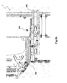
- Figures 1a -d thus depict various steps in the method according to the invention for fitting a bunk 1 in a limited space, here in a cab 2 for a heavy/commercial vehicle, e.g. a truck.
- Figure 1a shows how a mounting device 3 with at least two mountings 4a,b intended for the bunk 1 is initially situated/positioned and fitted in or at the cab's rear wall or inner panel 5.
- the two mountings 4a, b are connected to one another by an intermediate member 6, e.g. made of metal, and are thereby integrated to form a mounting device 3 which makes it easier to more exactly position and fit the bunk 1 relative to the wall/inner panel 5.
- FIG. 1b shows how the bunk 1 is lifted into the cab 2 by means of an undepicted bunk lifting device and is about to be placed on guide means or guide rails 7a,b situated in a supporting structure 8 in the rear space of the cab 2.
- the supporting structure 8 does at the same time comprise, under the bunk 1, storage spaces 9a-c which may be used for storage of tools, work clothes and other objects.
- a refrigerator (not depicted) is usually situated in the middle of the supporting structure 8.
- the outer storage spaces 9a,c are usually reachable from outside the vehicle via side hatches (not depicted) provided for the purpose in the outer bodywork or frame structure 10 of the cab 2.
- Figure 1c shows how the bunk 1 is moved in towards, and how its guide devices (not depicted) are placed in, guide rails 7a,b in which they then rest, and the bunk is about to be moved or pushed towards the rear wall/inner panel 5 of the cab 2.
- Figure 1d shows the bunk 1 when it has been moved or pushed rearwards towards its final fitting position and has been locked in position by the mountings 4a,b.
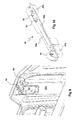
- Figure 2 depicts a view obliquely from in front of a right guide rail 7b and a right mounting 4b of the mounting device 3.
- the mounting 4b is here fitted to the rear wall/inner panel 5 of the cab 2 and the guide rail 7b is firmly attached in the vehicle's longitudinal direction to part of the cab's supporting structure 8.
- the guide rail 7b is provided at its forward end, as viewed in the vehicle's driving direction, with a supporting wheel 11 and is fitted at its rear end to the integrated mounting device via a threaded or welded connection.
- the supporting wheel 11 is adapted to supporting the bunk 1 from below when the bunk is in its final fitted position.
- FIG 3 depicts the mounting 4b in more detail as seen obliquely from in front.
- the mounting 4b comprises mainly a metal housing 12 fitted, e.g. by a welded connection, in a flange 13 in the mounting device 3, in which housing 12 a latch 14 is arranged for articulation about a spindle 15.
- the latch 14 is provided at the top with a chamfer 16 by means of which it can be forced rearwards to an open position against the action of a spring (not depicted).
- the housing 12 is also provided at the top at the front with a chamfer 17 which is opposite in direction to the chamfer 16 of the latch 14 and which makes it easier to guide into the mounting 4b a hinge pin provided in the bracket (see Figure 5 ).
- FIG 4 depicts in more detail as seen in side view a section through the mounting 4b according to the invention.
- the latch 14 disposed in the inner space of the housing 12 takes the form at the top of a hook and is urged to pivot anticlockwise (in the diagram) about its spindle 15 by a preloaded spring 18.
- the housing's chamfer 17, like the latch's chamfer 16, is configured to guide a connecting means disposed in the bunk, in the form of a hinge pin 19 in the bunk's bracket 20 (see Figure 5 ), down into the mounting 4b and thereby push the latch 14 clockwise to an open position so that the hinge pin 19 can drop all the way down into the mounting 4b. Thereafter the latch 14 reverts to a locking position and locks firmly the hinge pin 19 and hence the bracket and the bunk 1.
- Figure 5 depicts in more detail as seen obliquely from below one of the brackets 20 fitted to the bunk 1.
- the bracket 20 is fitted to the bottom 21 of the bunk 1, which bottom may be made of steel, plywood or composite material, and more specifically to the portion of the dividable bunk which constitutes the fixed element, i.e. the element which does not move when the width of the bunk 1 is altered.
- the bracket 20 extends transversely to the longitudinal direction of the bunk 1 and out past a long side 22 of the bunk 1 which faces towards the wall, and continues in the form of a curved portion 23 with a suitable radius before extending finally up along the bunk's long side 22.
- the curved portion 23 of the bracket 20 extends initially somewhat downwards before turning upwards, thereby being intended to provide space for the fabric, and, where applicable, the filling, which will need to be pushed downwards or upwards along the bunk's long side 22, depending on whether the bunk 1 is being put into its wider or narrower state.
- At least one locating stud 24 is also provided at the bottom of the bunk beside the bracket 20 and is made of low-friction material, e.g. plastic material.
- Figure 6 depicts in side view the bunk 1, the bracket 20a fitted to the bunk's bottom 21, and a locating stud 24.
- the bunk 1 is at one of the fitting stages in which the locating stud 24 is about to be lowered into a guide rail 7b.
- the fitter can push the bunk rearwards, relative to the vehicle's driving direction, to its final fitting position.
- the bunk 1 is provided with at least two locating studs 24a,b, e.g. made of plastic material
- the cab's supporting structure 8 is provided with at least two guide rails 7a,b, e.g. made of metal.
- Figure 7 depicts a section through a guide rail 7a,b in which it may seen that its side edges 25a,b are angled/obliquely positioned outwards away from its notional centreline so that the profile forms a hopper shape to make it easier to move the locating studs 24a,b into the guide rails 7a,b during the fitting of the bunk 1 and thereby ensure that the bunk 1 is positioned correctly sideways in the cab 2.
- At least two guide rails 7a,b are needed for the fitting operation according to this procedure and it is therefore also possible that each guide rail 7a,b may only have one side edge (not depicted). In that case, the two guide rails will still together have two obliquely positioned side edges 25a,b, each preferably oriented in its respective direction, which is sufficient to allow the bunk 1 to be moved in.
- Figures 8a -b depict the bunk 1 as seen from below and functional parts fitted to its bottom 21.
- Figure 8a shows for example that the bunk 1 can be divided, drawn apart, in a conventional manner, along a dividing line 26.
- a handle 27 provided at the forward long side 28 of the bunk 1 is intended to make it easier for the user to set the width of the bunk 1 but also to make it easier to lift the bunk 1 for access to the storage spaces 9a-c provided in the supporting structure 8.
- Two brackets 20a,b are provided at the bunk's bottom 21 and extend out past the edge of the rear/inner long side 22 of the bunk 1. Locating studs 24a,b are provided in the fixed bottom element of the bunk 1 beside or within the brackets 20a,b, i.e.
- Running rails 28a,b are also fitted in the bottom 21 of the bunk and are intended to cooperate with the supporting wheels 11 provided at the outer ends of the guide rails 7a,b.
- Figure 8b shows the bunk 1, the bracket 20b, the locating stud 24b and the running rail 28b in more detail as seen from below.
- Figure 9 depicts a bracket 20a and its hinge pin 19 in a connected and locked state with the mounting 4b.
- the length/height of the locating studs 24a,b is such that the connecting means provided in the brackets 20a,b, or the hinge pins 19, will be at a height position just above the mountings 4a,b, and when the locating studs 24a,b are just above the mountings 4a,b at the inner panel 5, the locating studs 24a,b will have simultaneously reached recesses 29 (see Figure 2 ) in the bottom of the guide rails 7a,b, whereupon they will drop into the recesses 29.
- the bunk 1 will also drop by its own weight, and the hinge pins 19 of the brackets will forcefully strike from above the chamfered edges 16,17 of the latches 14 and of the housing 12, thereby forcing the latches 14 to open against the force of the springs 18.
- the brackets 20 and the bunk 1 are thereby locked to the mounting device 3.
- Each mounting 4a,b and bracket 20a,b constitute a hinge which makes it possible for the bunk 1 at least partly to be folded up towards the wall/inner panel to provide access to the storage spaces 9a-c situated under the bunk 1. Folding the bunk 1 upwards is facilitated by conventionally arranged gas springs (not depicted).
- Figure 10 depicts a fitting aid in the form of an alternative and easily removable guide rail 30.
- This alternative guide rail 30 is provided on its underside with block-like fitting supports 31a,b which fit into, and may temporarily during the fitting phase be pressed down into, the fixed guide rails 7a,b integrated with the cab's/the bunk's supporting structure 8.
- This alternative guide rail 30 has side edges 32a,b angled outwards more than the integrated guide rail 7a,b and hence has a wider hopper shape which make it easier to position correctly the locating studs 24a,b of the bunk 1.
- This alternative guide rail 30 also has a portion 33 which is angled upwards or raised and is situated close to and in front, in the vehicle's direction, of the recess 34 in rail 30, which means that when the fitter pushes the bunk 1 rearwards the rear portion of the bunk 1 will be forced somewhat upwards before the locating studs 24a,b drop into the recess in the rail 30, causing the hinge pins 19 of the brackets 20 to drop with greater force towards the latches 14, push the latches 14 to open positions and drop all the way down into the mountings 4a,b.
- the upward-sloping or raised portion 33 thus strengthens the upward movement of the bunk 1, resulting in a greater drop height and thereby achieving more secure locking.
Landscapes
- Engineering & Computer Science (AREA)
- Mechanical Engineering (AREA)
- Transportation (AREA)
- Chemical & Material Sciences (AREA)
- Combustion & Propulsion (AREA)
- Health & Medical Sciences (AREA)
- Public Health (AREA)
- Manufacturing & Machinery (AREA)
- Body Structure For Vehicles (AREA)
- Conveying And Assembling Of Building Elements In Situ (AREA)
- Vehicle Step Arrangements And Article Storage (AREA)
- Supports Or Holders For Household Use (AREA)
- Mutual Connection Of Rods And Tubes (AREA)
Abstract
Description
- The present invention relates to a method, a system and devices for fitting a bunk in a limited space. The invention relates more specifically to a method, a system and devices for fitting a bunk at a rear wall/inner panel in a vehicle cab, and relates particularly to fitting a bunk which is of variable and adjustable width.
- Particularly in heavy/commercial vehicles it is desirable to provide a bunk in the cab to enable the driver to rest during long journeys/assignments. The bunk is usually situated behind the front row of seats, i.e. behind the driving and passenger seats. It is advantageous if the bunk can be narrowed, compressed, when not in use, so that the driving seat can unobstructedly be placed in such a position, possibly pushed far back, as to provide the driver with a good and comfortable driving posture. It is also advantageous if the bunk can be widened, expanded, when it is to be used for resting, since it will thus provide better comfort for the resting person. The bunk may also partly serve as an extra sitting location, e.g. when the vehicle is stationary, during breaks, etc. At such times it is primarily the central portion of the bunk which will be usable as a surface to sit on, since it is readily accessible between the front seats. If the bunk is used as a sitting location, it is advantageous if its springing is then slightly harder than when used for resting, to which end the bunk will need to be in a compressed state in which the springs in the mattress are closer together. The compressed state will also result in more legroom relative to the remainder of the cab interior, the instrument panel etc. Bunks of variable and adjustable width are already known and are not described in more detail here.
- The production of commercial/heavy vehicles always involves endeavouring to achieve more cost-effective constructional solutions and better methods for the assembly of parts in order to reduce manufacturing costs and achieve competitive advantages. Bunks of the kind here concerned comprise, owing to their construction, a number of parts, thereby increasing the weight of the bunk. This complicates manufacture. The bunk has to be lifted into the cab through the apertures normally provided in the cab, i.e. via the windscreen, side windows or doors, and thereafter be positioned correctly within the limited and cramped space in the cab. There is usually only room for one fitter in the cab during the fitting operation and he/she will only be able to be at the bunk's forward long side and will therefrom have to lift and manoeuvre the bunk into position and thereafter fit it firmly in the cab's supporting structure and/or in the cab's rear wall/inner panel by means of suitable tools and threaded connections. This is a burdensome and stressful operation even if lifting aids intended for the purpose are used as far as possible.
- The state of the art in this field does not solve the problem of easily, quickly and safely fitting a relatively heavy bunk in a limited space. It is usually necessary for two or more fitters to do heavy lifting and/or work in awkward postures.
- An object of the invention is to solve the above problem and propose a fitting method of the kind indicated in the introduction which renders correct fitting of bunks in limited spaces easier, quicker and safer.
- A further object of the invention is to propose a system which makes it possible to fit a bunk of said kind in limited spaces easily, quickly and safely.
- A further object of the invention is to propose a guide device to make it easier to move a bunk to a final fitting position.
- A further object of the invention is to propose a mounting means which makes it possible to fit the bunk easily, quickly and safely and whereby the bunk's own weight is used to cause it to be locked firmly to the wall/inner panel.
- A further object of the invention is that the mounting means should be so configured as to make it possible to fold the bunk up and down after completion of fitting.
- A further object of the invention is to propose a bracket which makes it easier to fit the bunk to the mounting easily, quickly and safely.
- These and further objects and advantages are achieved according to the invention by a method, a system and devices according to the features indicated in the characterising parts of
claims - The invention thus relates to a fitting method, a system and devices for making it easier to fit a bunk in a limited space, e.g. in a vehicle cab. The invention relates in particular to bunks which are of variable and optionally adjustable width, since these bunks often comprise many parts which make them heavier and hence more difficult to handle during fitting. The method involves the bunk being lifted into the cab from in front via the windscreen aperture and being positioned by means of guide devices or locating studs on at least two guide means or guide rails situated side by side against the cab's supporting structure and running in the vehicle's longitudinal direction. The bunk is thereafter pushed rearwards by the fitter towards the cab's rear wall/inner panel. When the bunk has been moved or pushed to its final position, the locating studs will reach recesses in the guide rails, whereupon the locating studs and the bunk will drop. Brackets attached to the bunk and provided with connection means in the form of hinges will drop, due to the weight of the bunk, into mounting means provided for the purpose and associated with the wall/inner panel and will be firmly locked hingingly therein by means of spring-loaded latches therein provided.
- The advantages of the invention are that the fitting of bunks of the kind indicated in the introduction is easier and quicker and can be done more safely. Moving the bunk in sideways is facilitated by the guide rails, which have side edges angled outwards and a hopper-like profile. When they have been placed in the guide rails, the fitter can easily use the bunk's locating studs to push the bunk rearwards towards its final position, and the bunk will of its own weight drop into a locked and finally fitted position. The fitter will not be subject to any heavy lifting or to awkward postures and the whole fitting operation will be completed in a short time, with consequent manufacturing cost advantages for the vehicle.
- Further features and advantages of the invention are indicated by the more detailed description of the invention set out below and the accompanying drawings and other claims.
- The invention is described in more detail below in various preferred embodiment examples with reference to the attached drawings.
-
Figures 1a -d depict various steps in the bunk fitting method according to the invention. -
Figure 2 depicts a view obliquely from in front of a mounting device and guide rail according to the invention, and parts of the cab's supporting structure. -
Figure 3 depicts a mounting as seen obliquely from in front in more detail. -
Figure 4 depicts in more detail from the side a section through the mounting according to the invention. -
Figure 5 depicts in more detail, as seen obliquely from below, a bracket attached to the bunk. -
Figure 6 depicts in side view a fitting stage in which the bunk is on its way down towards the guide rail. -
Figure 7 depicts schematically a section through the guide rail. -
Figures 8a -b depict the bunk and its functional parts as seen from below. -
Figure 9 depicts the hinge pin of a bracket pushed down into the mounting and locked firmly by the latch. -
Figure 10 depicts a fitting aid in the form of an alternative and easily removable guide rail. -
Figures 1a -d thus depict various steps in the method according to the invention for fitting abunk 1 in a limited space, here in acab 2 for a heavy/commercial vehicle, e.g. a truck.Figure 1a shows how amounting device 3 with at least twomountings 4a,b intended for thebunk 1 is initially situated/positioned and fitted in or at the cab's rear wall orinner panel 5. In this case the twomountings 4a, b are connected to one another by anintermediate member 6, e.g. made of metal, and are thereby integrated to form amounting device 3 which makes it easier to more exactly position and fit thebunk 1 relative to the wall/inner panel 5. The fact that the twomountings 4a,b are connected together not only achieves an improved collision characteristic but also ensures that exactly correct spacing and angles are maintained between the twomountings 4 a,b, thereby contributing to easier and more correct fitting. A further object of themember 6 is to absorb collision force.Figure 1b shows how thebunk 1 is lifted into thecab 2 by means of an undepicted bunk lifting device and is about to be placed on guide means or guiderails 7a,b situated in a supportingstructure 8 in the rear space of thecab 2. The supportingstructure 8 does at the same time comprise, under thebunk 1,storage spaces 9a-c which may be used for storage of tools, work clothes and other objects. A refrigerator (not depicted) is usually situated in the middle of the supportingstructure 8. Theouter storage spaces 9a,c are usually reachable from outside the vehicle via side hatches (not depicted) provided for the purpose in the outer bodywork orframe structure 10 of thecab 2.Figure 1c shows how thebunk 1 is moved in towards, and how its guide devices (not depicted) are placed in, guiderails 7a,b in which they then rest, and the bunk is about to be moved or pushed towards the rear wall/inner panel 5 of thecab 2.Figure 1d shows thebunk 1 when it has been moved or pushed rearwards towards its final fitting position and has been locked in position by themountings 4a,b. -
Figure 2 depicts a view obliquely from in front of aright guide rail 7b and a right mounting 4b of themounting device 3. The mounting 4b is here fitted to the rear wall/inner panel 5 of thecab 2 and theguide rail 7b is firmly attached in the vehicle's longitudinal direction to part of the cab's supportingstructure 8. Theguide rail 7b is provided at its forward end, as viewed in the vehicle's driving direction, with a supportingwheel 11 and is fitted at its rear end to the integrated mounting device via a threaded or welded connection. The supportingwheel 11 is adapted to supporting thebunk 1 from below when the bunk is in its final fitted position. -
Figure 3 depicts the mounting 4b in more detail as seen obliquely from in front. The mounting 4b comprises mainly ametal housing 12 fitted, e.g. by a welded connection, in aflange 13 in the mountingdevice 3, in which housing 12 alatch 14 is arranged for articulation about aspindle 15. Thelatch 14 is provided at the top with achamfer 16 by means of which it can be forced rearwards to an open position against the action of a spring (not depicted). Thehousing 12 is also provided at the top at the front with achamfer 17 which is opposite in direction to thechamfer 16 of thelatch 14 and which makes it easier to guide into the mounting 4b a hinge pin provided in the bracket (seeFigure 5 ). -
Figure 4 depicts in more detail as seen in side view a section through the mounting 4b according to the invention. Thelatch 14 disposed in the inner space of thehousing 12 takes the form at the top of a hook and is urged to pivot anticlockwise (in the diagram) about itsspindle 15 by apreloaded spring 18. The housing'schamfer 17, like the latch'schamfer 16, is configured to guide a connecting means disposed in the bunk, in the form of ahinge pin 19 in the bunk's bracket 20 (seeFigure 5 ), down into the mounting 4b and thereby push thelatch 14 clockwise to an open position so that thehinge pin 19 can drop all the way down into the mounting 4b. Thereafter thelatch 14 reverts to a locking position and locks firmly thehinge pin 19 and hence the bracket and thebunk 1. -
Figure 5 depicts in more detail as seen obliquely from below one of thebrackets 20 fitted to thebunk 1. Thebracket 20 is fitted to the bottom 21 of thebunk 1, which bottom may be made of steel, plywood or composite material, and more specifically to the portion of the dividable bunk which constitutes the fixed element, i.e. the element which does not move when the width of thebunk 1 is altered. Thebracket 20 extends transversely to the longitudinal direction of thebunk 1 and out past along side 22 of thebunk 1 which faces towards the wall, and continues in the form of acurved portion 23 with a suitable radius before extending finally up along the bunk'slong side 22. Thecurved portion 23 of thebracket 20 extends initially somewhat downwards before turning upwards, thereby being intended to provide space for the fabric, and, where applicable, the filling, which will need to be pushed downwards or upwards along the bunk'slong side 22, depending on whether thebunk 1 is being put into its wider or narrower state. At least one locatingstud 24 is also provided at the bottom of the bunk beside thebracket 20 and is made of low-friction material, e.g. plastic material. -
Figure 6 depicts in side view thebunk 1, thebracket 20a fitted to the bunk's bottom 21, and a locatingstud 24. Thebunk 1 is at one of the fitting stages in which the locatingstud 24 is about to be lowered into aguide rail 7b. When the locatingstud 24 has been lowered into theguide rail 7b, the fitter can push the bunk rearwards, relative to the vehicle's driving direction, to its final fitting position. Thebunk 1 is provided with at least two locatingstuds 24a,b, e.g. made of plastic material, and the cab's supportingstructure 8 is provided with at least twoguide rails 7a,b, e.g. made of metal. -
Figure 7 depicts a section through aguide rail 7a,b in which it may seen that itsside edges 25a,b are angled/obliquely positioned outwards away from its notional centreline so that the profile forms a hopper shape to make it easier to move the locatingstuds 24a,b into theguide rails 7a,b during the fitting of thebunk 1 and thereby ensure that thebunk 1 is positioned correctly sideways in thecab 2. At least twoguide rails 7a,b are needed for the fitting operation according to this procedure and it is therefore also possible that eachguide rail 7a,b may only have one side edge (not depicted). In that case, the two guide rails will still together have two obliquely positionedside edges 25a,b, each preferably oriented in its respective direction, which is sufficient to allow thebunk 1 to be moved in. -
Figures 8a -b depict thebunk 1 as seen from below and functional parts fitted to its bottom 21.Figure 8a shows for example that thebunk 1 can be divided, drawn apart, in a conventional manner, along adividing line 26. Ahandle 27 provided at the forward long side 28 of thebunk 1 is intended to make it easier for the user to set the width of thebunk 1 but also to make it easier to lift thebunk 1 for access to thestorage spaces 9a-c provided in the supportingstructure 8. Twobrackets 20a,b are provided at the bunk's bottom 21 and extend out past the edge of the rear/innerlong side 22 of thebunk 1. Locatingstuds 24a,b are provided in the fixed bottom element of thebunk 1 beside or within thebrackets 20a,b, i.e. nearer to the centre of thebunk 1, which means that thebrackets 20a,b and theguide rails 7a,b will not normally come into contact with one another during the pushing-in phase and will therefore not affect the lowering or moving of thebunk 1 into its final fitted position. Runningrails 28a,b are also fitted in the bottom 21 of the bunk and are intended to cooperate with the supportingwheels 11 provided at the outer ends of theguide rails 7a,b.Figure 8b shows thebunk 1, thebracket 20b, the locatingstud 24b and the runningrail 28b in more detail as seen from below. -
Figure 9 depicts abracket 20a and itshinge pin 19 in a connected and locked state with the mounting 4b. When the locatingstuds 24a,b have been lowered in and abut against the bottom of theguide rails 7a,b, the fitter can easily push thebunk 1 towards the rear wall/inner panel 5 of thecab 2. The length/height of the locatingstuds 24a,b is such that the connecting means provided in thebrackets 20a,b, or the hinge pins 19, will be at a height position just above themountings 4a,b, and when the locatingstuds 24a,b are just above themountings 4a,b at theinner panel 5, the locatingstuds 24a,b will have simultaneously reached recesses 29 (seeFigure 2 ) in the bottom of theguide rails 7a,b, whereupon they will drop into therecesses 29. Therefore thebunk 1 will also drop by its own weight, and the hinge pins 19 of the brackets will forcefully strike from above the chamfered edges 16,17 of thelatches 14 and of thehousing 12, thereby forcing thelatches 14 to open against the force of thesprings 18. This results in thehinge pin 19 dropping all the way down into the hook-like recesses of thelatches 14, after which thesprings 18 will urge thelatches 14 to automatically revert or snap back to their locking positions. Thebrackets 20 and thebunk 1 are thereby locked to the mountingdevice 3. - Each mounting 4a,b and
bracket 20a,b constitute a hinge which makes it possible for thebunk 1 at least partly to be folded up towards the wall/inner panel to provide access to thestorage spaces 9a-c situated under thebunk 1. Folding thebunk 1 upwards is facilitated by conventionally arranged gas springs (not depicted). -
Figure 10 depicts a fitting aid in the form of an alternative and easilyremovable guide rail 30. Thisalternative guide rail 30 is provided on its underside with block-like fitting supports 31a,b which fit into, and may temporarily during the fitting phase be pressed down into, the fixedguide rails 7a,b integrated with the cab's/the bunk's supportingstructure 8. Thisalternative guide rail 30 hasside edges 32a,b angled outwards more than the integratedguide rail 7a,b and hence has a wider hopper shape which make it easier to position correctly the locatingstuds 24a,b of thebunk 1. Thisalternative guide rail 30 also has aportion 33 which is angled upwards or raised and is situated close to and in front, in the vehicle's direction, of therecess 34 inrail 30, which means that when the fitter pushes thebunk 1 rearwards the rear portion of thebunk 1 will be forced somewhat upwards before the locatingstuds 24a,b drop into the recess in therail 30, causing the hinge pins 19 of thebrackets 20 to drop with greater force towards thelatches 14, push thelatches 14 to open positions and drop all the way down into themountings 4a,b. The upward-sloping or raisedportion 33 thus strengthens the upward movement of thebunk 1, resulting in a greater drop height and thereby achieving more secure locking. After the fitting operation, thesealternative guide rails 30 are removed and used again for subsequent fitting operations. - The above description is primarily intended to facilitate comprehension of the invention. Therefore, the invention is of course not limited to the embodiments indicated, since other variants of the invention are also possible and conceivable within the scope of the concept of the invention and the scope of protection of the claims set out below. Moreover, the invention is of course not limited solely to applications in a vehicle, since it is also usable with advantage in other contexts where it is desired to fit a bunk against a wall in limited and cramped spaces, e.g. in dormobiles, caravans, boats etc. It is of course also conceivable, instead of fitting guide rails on a supporting structure and having locating studs on the underside of the bunk, to do the opposite, i.e. exchange their places. Similarly, it is of course possible for the running rail and the supporting roller also to change places. What is also conceivable, in the same way as the alternative guide rail is provided with sides which are more distinctly angled outwards and a portion which is raised or angled upwards close to and in front of the recess, is that this same arrangement might also be provided in the guide rail first described which is integrated with the cab's or the bunk's supporting structure.
Claims (13)
- A method for fitting in a limited space adjacent to a wall/inner panel (5) a bunk (1) which is preferably of adjustable width and rests on a supporting structure (8), characterised- in that at least one mounting (4a,b) is first fitted to the wall/inner panel (5),- that guide means (24a,b) attached to the bunk are moved in towards, and lowered into, guide means (7a,b,30) provided on/associated with the supporting structure (8),- that the bunk (1) is pushed/moved towards the wall/inner panel (5) and towards its final fitting position, and- that the bunk (1) is caused by its own weight to push at least one connecting means (19) down into the mounting (4a,b), thereby causing the latter to hingingly lock the bunk (1) firmly in position.
- A method according to claim 1,
characterised- in that the guide means (24a,b) of the bunk (1) are pushed/moved into the guide means (7a,b,30) across a raised portion (33) and thereby impart to the bunk (1) a substantially vertical movement with the result that the locking means (19,20) of the bunk (1) drop with greater force into the mounting (4a,b). - A method according to claim 1 or 2,
characterised- in that the connecting means (19,20) of the bunk (1) are caused to automatically become locked firmly in the mounting (4a,b). - A system for fitting a bunk (1) in a limited space, comprising a bunk (1) which is preferably of variable and adjustable width, a wall/inner panel (5) which the bunk is intended to be fitted adjacent to, and a supporting structure (8) on which the bunk is intended to rest/bear,
characterised- in that a mounting device (3) is provided with at least two mountings (4a,b) at the wall/inner panel (5) against which the bunk (1) is intended to be fitted,- that the bunk (1) is provided with guide devices (24) which fit into guide means (7a,b) provided on or associated with the supporting structure (8) in the limited space,- that the bunk (1) is adapted to being pushed/moved by means of the guide devices (24) towards its final fitting position, and- that connection means (19,20) are associated with the bunk (1) and are pushed down into the mounting by the weight of the bunk (1). - A system according to claim 4, characterised by- comprising at least one guide rail (7a,b,30) which is provided with at least one recess (34) in its bottom.
- A system according to claim 5,
characterised- in that the guide rail (7a,b,30) is provided with a raised portion (33) at the bottom of the guide rail (7a,b,30) close to/before said recess (34). - A system according to claim 5 or 6,
characterised- in that the guide rail (7a,b,30) is provided with at least one side edge (32a,b) which is angled outwards obliquely away from the notional centreline of the guide rail (7a,b,30). - A system according to claims 5-7,
characterised- that the guide rail (7a,b,30) runs parallel with the vehicle's longitudinal direction. - A system according to any one of claims 4-8,
characterised- in that locating studs (24a,b) are provided at the bottom (21) of the bunk (1) and are intended to cooperate with the guide rail (7a,b,30). - A system according to claim 9,
characterised- in that the locating studs (24a,b) are substantially cylindrical in shape and made of low-friction material. - A system according to any one of claims 4-10, characterised by- a mounting device (3) for fitting a bunk (1) in a limited space, comprising a bunk (1) which is preferably of variable and adjustable width, a wall/inner panel (5) which the bunk (1) is intended to be fitted adjacent to, and a supporting structure (8) on which the bunk (1) is intended to rest/bear, whereby at least two mountings (4a,b) are integrated with one another via at least one member (6).
- A system according to any one of claims 4-11,
characterised by- a mounting (4a,b) for fitting a bunk in a limited space, and in that a housing (12) is adapted to accommodating a spring-loaded latch (14). - A system according to claim 12,
characterised- in that the mounting (4a,b) takes the form of a hinge and makes it possible for the bunk (1) in a fitted state to be folded up.
Applications Claiming Priority (1)
| Application Number | Priority Date | Filing Date | Title |
|---|---|---|---|
| SE0950666A SE534351C2 (en) | 2009-09-14 | 2009-09-14 | Procedures, systems and devices for mounting a bed in a confined space |
Publications (3)
| Publication Number | Publication Date |
|---|---|
| EP2295289A2 true EP2295289A2 (en) | 2011-03-16 |
| EP2295289A3 EP2295289A3 (en) | 2011-03-23 |
| EP2295289B1 EP2295289B1 (en) | 2018-12-19 |
Family
ID=43271843
Family Applications (1)
| Application Number | Title | Priority Date | Filing Date |
|---|---|---|---|
| EP10175645.0A Not-in-force EP2295289B1 (en) | 2009-09-14 | 2010-09-07 | Method, system and devices for fitting a bunk in a limited space |
Country Status (5)
| Country | Link |
|---|---|
| EP (1) | EP2295289B1 (en) |
| CN (1) | CN102019870B (en) |
| BR (1) | BRPI1003441A2 (en) |
| RU (1) | RU2533296C2 (en) |
| SE (1) | SE534351C2 (en) |
Cited By (3)
| Publication number | Priority date | Publication date | Assignee | Title |
|---|---|---|---|---|
| CN108674427A (en) * | 2018-04-03 | 2018-10-19 | 上海工程技术大学 | A kind of detachable compartment sleeping berth device |
| EP3534754A4 (en) * | 2016-11-04 | 2020-08-05 | Ford Otomotiv Sanayi Anonim Sirketi | FOLDING BED AND BED STORAGE FOR VEHICLES WITH CAB |
| WO2020222638A1 (en) * | 2019-04-29 | 2020-11-05 | Daf Trucks N.V. | Crash bed platform |
Families Citing this family (1)
| Publication number | Priority date | Publication date | Assignee | Title |
|---|---|---|---|---|
| RU206740U1 (en) * | 2021-04-28 | 2021-09-24 | Публичное акционерное общество "КАМАЗ" | Sleeping place of the vehicle cabin |
Family Cites Families (6)
| Publication number | Priority date | Publication date | Assignee | Title |
|---|---|---|---|---|
| SU1676891A1 (en) * | 1989-04-14 | 1991-09-15 | Калининский вагоностроительный завод им.М.И.Калинина | Compartment of sleeping carriage |
| US5984404A (en) * | 1997-02-25 | 1999-11-16 | Freightliner Corporation | Vehicle with bed raising and lowering system |
| ITTO20010624A1 (en) * | 2001-06-29 | 2002-12-29 | Iveco Fiat | CABIN OF AN INDUSTRIAL VEHICLE. |
| US7104593B2 (en) * | 2003-11-14 | 2006-09-12 | Freightliner Llc | Lower bunk for a vehicle |
| CN101209686A (en) * | 2006-12-25 | 2008-07-02 | 刘熙 | Novel multifunctional automobile |
| EP2058213B1 (en) * | 2007-11-07 | 2013-09-18 | Mo.T.I.S. GmbH Modular Truck Interior System | Device for holding interior fittings objects, rack system with a frame and commercial vehicle with a driver's cabin |
-
2009
- 2009-09-14 SE SE0950666A patent/SE534351C2/en not_active IP Right Cessation
-
2010
- 2010-09-07 EP EP10175645.0A patent/EP2295289B1/en not_active Not-in-force
- 2010-09-09 BR BRPI1003441-2A patent/BRPI1003441A2/en not_active Application Discontinuation
- 2010-09-13 RU RU2010137912/11A patent/RU2533296C2/en not_active IP Right Cessation
- 2010-09-14 CN CN201010284277.3A patent/CN102019870B/en not_active Expired - Fee Related
Non-Patent Citations (1)
| Title |
|---|
| None |
Cited By (5)
| Publication number | Priority date | Publication date | Assignee | Title |
|---|---|---|---|---|
| EP3534754A4 (en) * | 2016-11-04 | 2020-08-05 | Ford Otomotiv Sanayi Anonim Sirketi | FOLDING BED AND BED STORAGE FOR VEHICLES WITH CAB |
| CN108674427A (en) * | 2018-04-03 | 2018-10-19 | 上海工程技术大学 | A kind of detachable compartment sleeping berth device |
| CN108674427B (en) * | 2018-04-03 | 2024-04-26 | 上海工程技术大学 | Separable train carriage sleeper device |
| WO2020222638A1 (en) * | 2019-04-29 | 2020-11-05 | Daf Trucks N.V. | Crash bed platform |
| NL2023023B1 (en) * | 2019-04-29 | 2020-11-05 | Daf Trucks Nv | Crash bed platform |
Also Published As
| Publication number | Publication date |
|---|---|
| EP2295289A3 (en) | 2011-03-23 |
| BRPI1003441A2 (en) | 2012-05-29 |
| CN102019870B (en) | 2015-06-17 |
| SE0950666A1 (en) | 2011-03-15 |
| CN102019870A (en) | 2011-04-20 |
| RU2533296C2 (en) | 2014-11-20 |
| EP2295289B1 (en) | 2018-12-19 |
| SE534351C2 (en) | 2011-07-19 |
| RU2010137912A (en) | 2012-03-20 |
Similar Documents
| Publication | Publication Date | Title |
|---|---|---|
| EP3233550B1 (en) | Modified door opening of a motorized vehicle for accommodating a ramp system and method thereof | |
| US8585116B2 (en) | Vehicular utility bed having end wall and seat bottom portion and vehicles including same | |
| DE69400336T2 (en) | Additional folding seat for vehicles | |
| US20090126179A1 (en) | Vehicle Conversion Assembly and Method of Converting a Vehicle | |
| JP2017504511A (en) | Tailgate and vehicle with loading area extension for multi-use vehicles | |
| WO2008061233A2 (en) | Vehicle seat back frame and method | |
| WO2014022568A1 (en) | Vehicle door armrest | |
| EP2295289B1 (en) | Method, system and devices for fitting a bunk in a limited space | |
| CN100493951C (en) | Low profile seat suspension | |
| EP0980817A2 (en) | Method for manufacturing a rear structure for a motor vehicle | |
| CN103946105A (en) | Group of motor vehicles | |
| US11059403B2 (en) | Reinforced rear seat assemblies for vehicles | |
| DE112011101835T5 (en) | Structure of the rear part of a vehicle body | |
| US20130026328A1 (en) | Seat raiser for spacing a seat rail from the vehicle floor | |
| JP2015074251A (en) | Body structure | |
| JP2010111215A (en) | Floor board structure for automobile | |
| WO2008073026A1 (en) | Bed arrangement for vehicles | |
| JP6569030B1 (en) | Car interior support unit | |
| JP6160593B2 (en) | Rear body structure of the vehicle | |
| JP4717628B2 (en) | rear seat | |
| JPH0412825Y2 (en) | ||
| KR102295867B1 (en) | Vechicle seat extension device | |
| US12565124B2 (en) | Seat rail | |
| JPS6350188Y2 (en) | ||
| KR100384595B1 (en) | struture for mounting rear seat of RV vehicle |
Legal Events
| Date | Code | Title | Description |
|---|---|---|---|
| PUAI | Public reference made under article 153(3) epc to a published international application that has entered the european phase |
Free format text: ORIGINAL CODE: 0009012 |
|
| PUAL | Search report despatched |
Free format text: ORIGINAL CODE: 0009013 |
|
| AK | Designated contracting states |
Kind code of ref document: A2 Designated state(s): AL AT BE BG CH CY CZ DE DK EE ES FI FR GB GR HR HU IE IS IT LI LT LU LV MC MK MT NL NO PL PT RO SE SI SK SM TR |
|
| AX | Request for extension of the european patent |
Extension state: BA ME RS |
|
| AK | Designated contracting states |
Kind code of ref document: A3 Designated state(s): AL AT BE BG CH CY CZ DE DK EE ES FI FR GB GR HR HU IE IS IT LI LT LU LV MC MK MT NL NO PL PT RO SE SI SK SM TR |
|
| AX | Request for extension of the european patent |
Extension state: BA ME RS |
|
| 17P | Request for examination filed |
Effective date: 20110923 |
|
| GRAP | Despatch of communication of intention to grant a patent |
Free format text: ORIGINAL CODE: EPIDOSNIGR1 |
|
| STAA | Information on the status of an ep patent application or granted ep patent |
Free format text: STATUS: GRANT OF PATENT IS INTENDED |
|
| INTG | Intention to grant announced |
Effective date: 20180713 |
|
| GRAS | Grant fee paid |
Free format text: ORIGINAL CODE: EPIDOSNIGR3 |
|
| GRAA | (expected) grant |
Free format text: ORIGINAL CODE: 0009210 |
|
| STAA | Information on the status of an ep patent application or granted ep patent |
Free format text: STATUS: THE PATENT HAS BEEN GRANTED |
|
| AK | Designated contracting states |
Kind code of ref document: B1 Designated state(s): AL AT BE BG CH CY CZ DE DK EE ES FI FR GB GR HR HU IE IS IT LI LT LU LV MC MK MT NL NO PL PT RO SE SI SK SM TR |
|
| REG | Reference to a national code |
Ref country code: GB Ref legal event code: FG4D |
|
| REG | Reference to a national code |
Ref country code: CH Ref legal event code: EP |
|
| REG | Reference to a national code |
Ref country code: IE Ref legal event code: FG4D |
|
| REG | Reference to a national code |
Ref country code: DE Ref legal event code: R096 Ref document number: 602010055879 Country of ref document: DE |
|
| REG | Reference to a national code |
Ref country code: AT Ref legal event code: REF Ref document number: 1078314 Country of ref document: AT Kind code of ref document: T Effective date: 20190115 |
|
| REG | Reference to a national code |
Ref country code: NL Ref legal event code: MP Effective date: 20181219 |
|
| PG25 | Lapsed in a contracting state [announced via postgrant information from national office to epo] |
Ref country code: LT Free format text: LAPSE BECAUSE OF FAILURE TO SUBMIT A TRANSLATION OF THE DESCRIPTION OR TO PAY THE FEE WITHIN THE PRESCRIBED TIME-LIMIT Effective date: 20181219 Ref country code: FI Free format text: LAPSE BECAUSE OF FAILURE TO SUBMIT A TRANSLATION OF THE DESCRIPTION OR TO PAY THE FEE WITHIN THE PRESCRIBED TIME-LIMIT Effective date: 20181219 Ref country code: NO Free format text: LAPSE BECAUSE OF FAILURE TO SUBMIT A TRANSLATION OF THE DESCRIPTION OR TO PAY THE FEE WITHIN THE PRESCRIBED TIME-LIMIT Effective date: 20190319 Ref country code: LV Free format text: LAPSE BECAUSE OF FAILURE TO SUBMIT A TRANSLATION OF THE DESCRIPTION OR TO PAY THE FEE WITHIN THE PRESCRIBED TIME-LIMIT Effective date: 20181219 Ref country code: HR Free format text: LAPSE BECAUSE OF FAILURE TO SUBMIT A TRANSLATION OF THE DESCRIPTION OR TO PAY THE FEE WITHIN THE PRESCRIBED TIME-LIMIT Effective date: 20181219 Ref country code: BG Free format text: LAPSE BECAUSE OF FAILURE TO SUBMIT A TRANSLATION OF THE DESCRIPTION OR TO PAY THE FEE WITHIN THE PRESCRIBED TIME-LIMIT Effective date: 20190319 |
|
| REG | Reference to a national code |
Ref country code: LT Ref legal event code: MG4D |
|
| REG | Reference to a national code |
Ref country code: AT Ref legal event code: MK05 Ref document number: 1078314 Country of ref document: AT Kind code of ref document: T Effective date: 20181219 |
|
| PG25 | Lapsed in a contracting state [announced via postgrant information from national office to epo] |
Ref country code: GR Free format text: LAPSE BECAUSE OF FAILURE TO SUBMIT A TRANSLATION OF THE DESCRIPTION OR TO PAY THE FEE WITHIN THE PRESCRIBED TIME-LIMIT Effective date: 20190320 Ref country code: SE Free format text: LAPSE BECAUSE OF FAILURE TO SUBMIT A TRANSLATION OF THE DESCRIPTION OR TO PAY THE FEE WITHIN THE PRESCRIBED TIME-LIMIT Effective date: 20181219 Ref country code: AL Free format text: LAPSE BECAUSE OF FAILURE TO SUBMIT A TRANSLATION OF THE DESCRIPTION OR TO PAY THE FEE WITHIN THE PRESCRIBED TIME-LIMIT Effective date: 20181219 |
|
| PG25 | Lapsed in a contracting state [announced via postgrant information from national office to epo] |
Ref country code: NL Free format text: LAPSE BECAUSE OF FAILURE TO SUBMIT A TRANSLATION OF THE DESCRIPTION OR TO PAY THE FEE WITHIN THE PRESCRIBED TIME-LIMIT Effective date: 20181219 |
|
| PG25 | Lapsed in a contracting state [announced via postgrant information from national office to epo] |
Ref country code: IT Free format text: LAPSE BECAUSE OF FAILURE TO SUBMIT A TRANSLATION OF THE DESCRIPTION OR TO PAY THE FEE WITHIN THE PRESCRIBED TIME-LIMIT Effective date: 20181219 Ref country code: ES Free format text: LAPSE BECAUSE OF FAILURE TO SUBMIT A TRANSLATION OF THE DESCRIPTION OR TO PAY THE FEE WITHIN THE PRESCRIBED TIME-LIMIT Effective date: 20181219 Ref country code: PT Free format text: LAPSE BECAUSE OF FAILURE TO SUBMIT A TRANSLATION OF THE DESCRIPTION OR TO PAY THE FEE WITHIN THE PRESCRIBED TIME-LIMIT Effective date: 20190419 Ref country code: CZ Free format text: LAPSE BECAUSE OF FAILURE TO SUBMIT A TRANSLATION OF THE DESCRIPTION OR TO PAY THE FEE WITHIN THE PRESCRIBED TIME-LIMIT Effective date: 20181219 Ref country code: PL Free format text: LAPSE BECAUSE OF FAILURE TO SUBMIT A TRANSLATION OF THE DESCRIPTION OR TO PAY THE FEE WITHIN THE PRESCRIBED TIME-LIMIT Effective date: 20181219 |
|
| PG25 | Lapsed in a contracting state [announced via postgrant information from national office to epo] |
Ref country code: RO Free format text: LAPSE BECAUSE OF FAILURE TO SUBMIT A TRANSLATION OF THE DESCRIPTION OR TO PAY THE FEE WITHIN THE PRESCRIBED TIME-LIMIT Effective date: 20181219 Ref country code: SK Free format text: LAPSE BECAUSE OF FAILURE TO SUBMIT A TRANSLATION OF THE DESCRIPTION OR TO PAY THE FEE WITHIN THE PRESCRIBED TIME-LIMIT Effective date: 20181219 Ref country code: IS Free format text: LAPSE BECAUSE OF FAILURE TO SUBMIT A TRANSLATION OF THE DESCRIPTION OR TO PAY THE FEE WITHIN THE PRESCRIBED TIME-LIMIT Effective date: 20190419 Ref country code: SM Free format text: LAPSE BECAUSE OF FAILURE TO SUBMIT A TRANSLATION OF THE DESCRIPTION OR TO PAY THE FEE WITHIN THE PRESCRIBED TIME-LIMIT Effective date: 20181219 Ref country code: EE Free format text: LAPSE BECAUSE OF FAILURE TO SUBMIT A TRANSLATION OF THE DESCRIPTION OR TO PAY THE FEE WITHIN THE PRESCRIBED TIME-LIMIT Effective date: 20181219 |
|
| REG | Reference to a national code |
Ref country code: DE Ref legal event code: R097 Ref document number: 602010055879 Country of ref document: DE |
|
| PLBE | No opposition filed within time limit |
Free format text: ORIGINAL CODE: 0009261 |
|
| STAA | Information on the status of an ep patent application or granted ep patent |
Free format text: STATUS: NO OPPOSITION FILED WITHIN TIME LIMIT |
|
| PG25 | Lapsed in a contracting state [announced via postgrant information from national office to epo] |
Ref country code: AT Free format text: LAPSE BECAUSE OF FAILURE TO SUBMIT A TRANSLATION OF THE DESCRIPTION OR TO PAY THE FEE WITHIN THE PRESCRIBED TIME-LIMIT Effective date: 20181219 Ref country code: DK Free format text: LAPSE BECAUSE OF FAILURE TO SUBMIT A TRANSLATION OF THE DESCRIPTION OR TO PAY THE FEE WITHIN THE PRESCRIBED TIME-LIMIT Effective date: 20181219 |
|
| 26N | No opposition filed |
Effective date: 20190920 |
|
| PG25 | Lapsed in a contracting state [announced via postgrant information from national office to epo] |
Ref country code: SI Free format text: LAPSE BECAUSE OF FAILURE TO SUBMIT A TRANSLATION OF THE DESCRIPTION OR TO PAY THE FEE WITHIN THE PRESCRIBED TIME-LIMIT Effective date: 20181219 |
|
| PG25 | Lapsed in a contracting state [announced via postgrant information from national office to epo] |
Ref country code: TR Free format text: LAPSE BECAUSE OF FAILURE TO SUBMIT A TRANSLATION OF THE DESCRIPTION OR TO PAY THE FEE WITHIN THE PRESCRIBED TIME-LIMIT Effective date: 20181219 |
|
| REG | Reference to a national code |
Ref country code: DE Ref legal event code: R119 Ref document number: 602010055879 Country of ref document: DE |
|
| PG25 | Lapsed in a contracting state [announced via postgrant information from national office to epo] |
Ref country code: MC Free format text: LAPSE BECAUSE OF FAILURE TO SUBMIT A TRANSLATION OF THE DESCRIPTION OR TO PAY THE FEE WITHIN THE PRESCRIBED TIME-LIMIT Effective date: 20181219 |
|
| REG | Reference to a national code |
Ref country code: CH Ref legal event code: PL |
|
| PG25 | Lapsed in a contracting state [announced via postgrant information from national office to epo] |
Ref country code: CH Free format text: LAPSE BECAUSE OF NON-PAYMENT OF DUE FEES Effective date: 20190930 Ref country code: LI Free format text: LAPSE BECAUSE OF NON-PAYMENT OF DUE FEES Effective date: 20190930 Ref country code: DE Free format text: LAPSE BECAUSE OF NON-PAYMENT OF DUE FEES Effective date: 20200401 Ref country code: IE Free format text: LAPSE BECAUSE OF NON-PAYMENT OF DUE FEES Effective date: 20190907 Ref country code: LU Free format text: LAPSE BECAUSE OF NON-PAYMENT OF DUE FEES Effective date: 20190907 |
|
| REG | Reference to a national code |
Ref country code: BE Ref legal event code: MM Effective date: 20190930 |
|
| PG25 | Lapsed in a contracting state [announced via postgrant information from national office to epo] |
Ref country code: BE Free format text: LAPSE BECAUSE OF NON-PAYMENT OF DUE FEES Effective date: 20190930 |
|
| GBPC | Gb: european patent ceased through non-payment of renewal fee |
Effective date: 20190907 |
|
| PG25 | Lapsed in a contracting state [announced via postgrant information from national office to epo] |
Ref country code: FR Free format text: LAPSE BECAUSE OF NON-PAYMENT OF DUE FEES Effective date: 20190930 Ref country code: GB Free format text: LAPSE BECAUSE OF NON-PAYMENT OF DUE FEES Effective date: 20190907 |
|
| PG25 | Lapsed in a contracting state [announced via postgrant information from national office to epo] |
Ref country code: CY Free format text: LAPSE BECAUSE OF FAILURE TO SUBMIT A TRANSLATION OF THE DESCRIPTION OR TO PAY THE FEE WITHIN THE PRESCRIBED TIME-LIMIT Effective date: 20181219 |
|
| PG25 | Lapsed in a contracting state [announced via postgrant information from national office to epo] |
Ref country code: HU Free format text: LAPSE BECAUSE OF FAILURE TO SUBMIT A TRANSLATION OF THE DESCRIPTION OR TO PAY THE FEE WITHIN THE PRESCRIBED TIME-LIMIT; INVALID AB INITIO Effective date: 20100907 Ref country code: MT Free format text: LAPSE BECAUSE OF FAILURE TO SUBMIT A TRANSLATION OF THE DESCRIPTION OR TO PAY THE FEE WITHIN THE PRESCRIBED TIME-LIMIT Effective date: 20181219 |
|
| PG25 | Lapsed in a contracting state [announced via postgrant information from national office to epo] |
Ref country code: MK Free format text: LAPSE BECAUSE OF FAILURE TO SUBMIT A TRANSLATION OF THE DESCRIPTION OR TO PAY THE FEE WITHIN THE PRESCRIBED TIME-LIMIT Effective date: 20181219 |