EP2295164A2 - A die former - Google Patents
A die former Download PDFInfo
- Publication number
- EP2295164A2 EP2295164A2 EP20100173691 EP10173691A EP2295164A2 EP 2295164 A2 EP2295164 A2 EP 2295164A2 EP 20100173691 EP20100173691 EP 20100173691 EP 10173691 A EP10173691 A EP 10173691A EP 2295164 A2 EP2295164 A2 EP 2295164A2
- Authority
- EP
- European Patent Office
- Prior art keywords
- former
- die
- component
- mould
- pegs
- Prior art date
- Legal status (The legal status is an assumption and is not a legal conclusion. Google has not performed a legal analysis and makes no representation as to the accuracy of the status listed.)
- Granted
Links
Images



Classifications
-
- B—PERFORMING OPERATIONS; TRANSPORTING
- B21—MECHANICAL METAL-WORKING WITHOUT ESSENTIALLY REMOVING MATERIAL; PUNCHING METAL
- B21D—WORKING OR PROCESSING OF SHEET METAL OR METAL TUBES, RODS OR PROFILES WITHOUT ESSENTIALLY REMOVING MATERIAL; PUNCHING METAL
- B21D37/00—Tools as parts of machines covered by this subclass
- B21D37/10—Die sets; Pillar guides
- B21D37/12—Particular guiding equipment, e.g. pliers; Special arrangements for interconnection or cooperation of dies
-
- B—PERFORMING OPERATIONS; TRANSPORTING
- B21—MECHANICAL METAL-WORKING WITHOUT ESSENTIALLY REMOVING MATERIAL; PUNCHING METAL
- B21D—WORKING OR PROCESSING OF SHEET METAL OR METAL TUBES, RODS OR PROFILES WITHOUT ESSENTIALLY REMOVING MATERIAL; PUNCHING METAL
- B21D22/00—Shaping without cutting, by stamping, spinning, or deep-drawing
- B21D22/02—Stamping using rigid devices or tools
-
- B—PERFORMING OPERATIONS; TRANSPORTING
- B21—MECHANICAL METAL-WORKING WITHOUT ESSENTIALLY REMOVING MATERIAL; PUNCHING METAL
- B21D—WORKING OR PROCESSING OF SHEET METAL OR METAL TUBES, RODS OR PROFILES WITHOUT ESSENTIALLY REMOVING MATERIAL; PUNCHING METAL
- B21D43/00—Feeding, positioning or storing devices combined with, or arranged in, or specially adapted for use in connection with, apparatus for working or processing sheet metal, metal tubes or metal profiles; Associations therewith of cutting devices
- B21D43/003—Positioning devices
-
- B—PERFORMING OPERATIONS; TRANSPORTING
- B21—MECHANICAL METAL-WORKING WITHOUT ESSENTIALLY REMOVING MATERIAL; PUNCHING METAL
- B21J—FORGING; HAMMERING; PRESSING METAL; RIVETING; FORGE FURNACES
- B21J13/00—Details of machines for forging, pressing, or hammering
- B21J13/02—Dies or mountings therefor
-
- B—PERFORMING OPERATIONS; TRANSPORTING
- B21—MECHANICAL METAL-WORKING WITHOUT ESSENTIALLY REMOVING MATERIAL; PUNCHING METAL
- B21K—MAKING FORGED OR PRESSED METAL PRODUCTS, e.g. HORSE-SHOES, RIVETS, BOLTS OR WHEELS
- B21K3/00—Making engine or like machine parts not covered by sub-groups of B21K1/00; Making propellers or the like
- B21K3/04—Making engine or like machine parts not covered by sub-groups of B21K1/00; Making propellers or the like blades, e.g. for turbines; Upsetting of blade roots
-
- B—PERFORMING OPERATIONS; TRANSPORTING
- B21—MECHANICAL METAL-WORKING WITHOUT ESSENTIALLY REMOVING MATERIAL; PUNCHING METAL
- B21D—WORKING OR PROCESSING OF SHEET METAL OR METAL TUBES, RODS OR PROFILES WITHOUT ESSENTIALLY REMOVING MATERIAL; PUNCHING METAL
- B21D53/00—Making other particular articles
- B21D53/78—Making other particular articles propeller blades; turbine blades
Definitions
- the present invention relates to a die former and more particularly to a die former utilised in hot creep forming or superplastic forming.
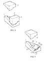
- FIGS. 1 to 6 of the attached drawings illustrate a typical prior art forming process in which a die former 100 is utilised.
- the die former 100 comprises a lower die 1 and an upper die combination formed by die parts 2, 3.
- a component in the form of a twisted blade preform 4 is placed within the die former 100 between the lower die 1 and upper die 2, 3.
- the lower die 1 is static while the upper die 2, 3 is forced under an appropriate load pressure vertically downward towards the lower die 1 such that the mould parts 101, which are typically recesses in the die parts 1, 2, 3 (only shown in lower die 1), are associated to further form the component 4.
- the component 4 and therefore the die parts 1, 2 and 3 are at elevated temperatures in order to provide the hot forming process as required.
- the forming process may include inducing a twist in a component by the opposed shape of the die parts 1, 2, 3 as they are forced together.
- the component 4 is placed in the lower die 1 and typically such that a root part 102 of the component 4 is in position so that an end face 21 engages a reciprocal face 11 in a root stop 103 of the die former 100. Furthermore, a trailing edge face 20 of the component 4 engages a reciprocal edge face 10 within the die former 100 about a periphery 50 of the mould portion 101.
- the die parts 2, 3 are respectively brought down forcefully and vertically towards the lower die 1.
- the root portion 102 of the component 4 will be held and formed. This will be achieved through the die part 3, as indicated, being forcefully moved down to engage the root part 102 to allow shaping and forming under heat and pressure.
- the force applied by the die part 3 will cause forming of the root part 102 into its desired, fully formed, final state.
- Figure 3 indicates the position of the die part 3 during the forming process while figure 4 illustrates the component in position with the die part 3 for root formation removed for clarity.
- FIG. 5 illustrates the second die part 2 is adjacent to the first die part 3 and as indicated within the mould parts of the die former 100, shaping and forming of the component 4 achieved.
- Figure 6 illustrates the component in its fully completed and formed state presented upon the lower die part 1, with other die parts 2, 3 removed for clarity.
- the objective of a forming process is to fully form a component, such as a turbine blade, from a rough formed shape into the desired shape typically at high temperature, generally 600°C to 700°C.
- the process is typically two stage with an initial first die part 3 brought down followed by a second die part 2.
- the initial rough formed shape will clearly not be in its final form, and may not fit accurately into the die former, either the lower die 1 or the mould parts of the die former; particularly if a twist is to be formed or extended in the component.
- an operator is required to adjust, typically using long rigid bars, the position of the component 4 in the mould parts to ensure that the component remains against the stops 10, 11 in the mould parts.
- a tip of a blade (as an example of a component) may be in a poor position relative to the stops 10, 11.
- parts of the component 4 can be positioned such that the die parts 2, 3 must be re-opened and the component repositioned before the dies 2, 3 are re-closed again for forming, in an attempt to improve blade tip position and the overall forming process itself.
- Such inaccuracies create processing problems as well as potential difficulties with final formed component shape accuracy.
- a mould former typically comprises opposed mould portions in die parts
- pegs or blocks are provided which interlock with each other in order to appropriately force positioning for the component during the forming processes.
- the further forming processes may extend a twist along an axis of the component.
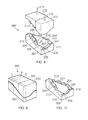
- Figure 7 provides an exploded perspective view of a die former 200 in accordance with the present invention.
- the die former 200 comprises a lower die 201 and an upper die formed by die parts 202, 203.
- the die former 200 is arranged to form a component 204 from an initial state to a final, or nearly final, shape.
- the component 204 includes a root portion 205 as well as leading and trailing edges 206, 207.
- the root portion 205 includes an end face 208 which engages a stop 209 in a root recess 210. In such circumstances, the root portion 205 enters the root recess 210 to locate that part of the component 204.
- pegs 211, 212 are provided respectively in the lower die 201 and in the upper die or at least die part 202 of the upper die.
- the pegs 211, 212 are in the form of teeth which have a gap between them such that the pegs in the opposed mould portions alternate and fill the gap.
- the pegs 211, 212 in opposed lower and upper die parts engage at least a part of the edges 206, 207 of the component 204.
- the pegs 211, 212 are located about a periphery of mould portion 213 to constrain and locate the component 204, particularly during the forming processes.
- a more consistent barrier or stop is created with the edges 206, 207 of the component 204, in order to ensure location of the component 204 in use without the necessity of opening the dies 201, 203 during the process of forming for repositioning.
- the dies 201, 202, 203 are open to enable the component 204 to be loaded into the lower die 201 for forming processes as required.
- Figure 8 illustrates an initial step of the forming process.
- the upper die or die parts 202, 203 are forcefully moved in the direction of arrowheads 214, 215, as described above with regard to die parts 2, 3 in figures 1 to 6 .
- die part 203 engages the root portion 205 to locate the component 204, while the die part 202 engages the tip part of the component 204 to provide the hot forming processes as described above.
- the die former 200, as well as the component 204 will be at elevated temperature, typically in the range of 600°C to 700°C for hot creep forming of blades utilised in gas turbine engines.
- Figure 9 illustrates the lower die 201 and upper die formed by parts 202, 203 in a closed position, whereby hot forming and in particular hot creep forming occurs within a former mould created by respective mould portions in recesses in the dies 201, 202, 203.
- cross-sectional planes A, B and C are illustrated by broken lines and these cross-sections A, B and C are illustrated below respectively by figures 11, 12 and 13 .
- Figure 10 illustrates the component 204 in its final moulded state within the lower die 201.
- the edges 206, 207 of the component 204 are generally constrained and stopped by the pegs 212.
- the pegs 212 are filled by pegs (not shown) from the opposed upper die, namely pegs 211 about the opposed mould portion in that upper die and in particular upper die portion 202.
- Figures 11 to 13 illustrate cross sections A, B, C as depicted in figure 9 .
- the pegs 211, 212 act as teeth which encompass the component 204 around the leading edge 206 and trailing edge 207 in the former mould defined between the die parts 201, 202, 203.
- the initial component 204 is in a relatively rough state and therefore may be spaced from the periphery of the former mould created between the die parts 201, 202, 203.
- the pegs or teeth will be along that former mould periphery, and therefore spaced from the component 204 as initially presented; but the component 204, under the forming pressure and temperature which create creep or other forming processes, will move towards the edge created by the pegs 211, 212 acting as a periphery around the former mould. Thus, the component 204 will move to be formed during the forming process towards the peripheral edge created by the interlocking pegs 211, 212.
- Figures 11 to 13 show the component 204 in its final formed state towards the end of the forming process.
- the component in the form of a blade
- the component has moved to the edges of the former mould created by opposed mould portions in the dies 201, 202.
- the gap between the pegs 211, 212 depicted in figures 11 to 13 is much greater than in reality for clarity of definition between the die parts 201, 202, 203. In reality, the periphery created by the pegs 211, 212 will be more finely defined and therefore more appropriate for blade edge formation.
- the angle 225 which defines the twist in the component 204 may be in the range of up to 30 degrees.
- Figure 11 and figure 12 show cross-sections A, B. It will be seen that the alternation between the pegs 211, 212 is provided while the component 204 in the twisted state is formed in the former mould created between the respective die parts 201, 202.
- the alternating pegs 211, 212 define an accurate periphery 250 for the former mould and therefore create an edge barrier or stop for the forming process.
- Figure 13 illustrates cross-section C as depicted in the die former 200 shown in figure 9 .
- the periphery 250 is shown by a broken line and extends from one end of the die former 201 to the other in a curve or slope. This curve or slope is again replicated by the interlocking and engaged pegs 211, 212 to define the periphery 250 within which a component 204 is formed.
- the die part 203 is utilised in that part of the die former associated with the root portion of the component 204.
- the keying and alignment created by the root portion and stops within the root recess can be utilised to ensure appropriate alignment between the die part 203 and the lower die 201.
- accurate alignment is required in order to create an accurate periphery for the leading and trailing edges of the component.
- Such alignment may be achieved through configuring the pegs 211, 212 to have angled or otherwise shaped surfaces which urge towards the desired peripheral edge in the closed former mould state between the lower die 201 and the upper die part 202. In such circumstances, in the final closed position, correct alignment will be achieved to define the leading and trailing edges as well as the component 204 itself, between the die parts 201, 202, 203.
- the upper die 202 generally is movable, while the lower die 201 is static.
- the die parts 202, 203 may move down together and may be combined into a unitary die former if required.
- the die parts 202, 203 may move down separately in sequential order.
- one of the die parts 202, 203 may move down partially and the other die part 203, 202 then fully engage the component 204, before the first die part 202, 203 again moves into a fully closed position.
- the forming processes utilised with a die former in accordance with the present invention may include hot creep or superplastic forming, and in such circumstances sequencing of movement of the die parts towards the final closed shape may be required for most efficient forming of the final shape.
- movement of the component is restricted during the forming processes resulting in a better final position, defined and confined by the periphery defined by the interlocking pegs.
- Such better control of the position eliminates the need for an operator to continually reposition the component during the forming processes and therefore reduces complexity and potential error in the processes.
- the pegs, as indicated take the form of teeth, and so through their interlocking nature, as indicated, will restrict radial movement as well as lateral movement between the lower die and the upper die, again creating better consistency in the former mould in the forming processes.
- the number of pegs and the space between the pegs will depend upon operational requirements. Typically a small number of pegs is used, in order to reduce complexity within the die parts and to provide smooth sections for the periphery with limited interengagement gaps. Furthermore, there will be small dimension gaps, in use, between adjacent pegs from the alternating upper and lower die parts.
- the pegs will be shaped and configured for appropriate interlocking to define the periphery within the former mould created between the die parts. In such circumstances the pegs will have a height sufficient to create such interengagement and provide robust stop barriers at the periphery to the former mould to create the leading and trailing edges as defined above in the component. Greater depth of interengagement will help with alignment and with the strength of the stop barrier created.
- the pegs may take a number of cross-sectional profiles. These profiles, for example, may be circular, rectangular, rhomboidal, oblong or obround. Furthermore, the profiles may be in a single plane, two planes/dimensions or fully three-dimensional, either singularly or in combination, to define (through their interengagement) the peripheral stop for the former mould in the die former.
- the pressure and temperature within the die former creates forming through a hot creep process, and containment of the "flow" of the component during that process is effected by the interengagement at the peripheral edge of the former mould.
- the material of the component will generally not be sufficiently flaccid that a fluid tight peripheral edge must be created by the interengagement between the pegs. Nevertheless, the gaps between the pegs should be sufficiently small that no unacceptable roughening of the edge is created in use.
- dies can be formed in a single piece, in accordance with the present invention, due to the alignment effects of the pegs interengaging with each other. Dies can be utilised for hot creep forming as well as superplastic forming.
- a die former in accordance with the present invention will be specifically shaped for each particular application.
- the pegs in each die part or opposed mould portion may be of different sizes and shapes, but reciprocation between opposed pegs, in terms of spaces and gaps between the pegs, in order to define the peripheral edge must be considered.
- the pegs may be of different depths as required.
- corner edge is the corner angle between the peg and mould parts of the die which defines the shape of the edge periphery to the former mould in accordance with aspects of the present invention.
- this corner edge may be chamfered, radiused or angled in order to create the edge shape as required.
- the pegs to create the periphery edge to the former mould in the die parts may be formed from the same material as the die parts and integrally formed with those die parts; or, alternatively, may be inset and secured as required in use.
- the pegs may be formed of a different material from the mould itself.
- a seaming edge or holder may be created and supported upon the pegs to act as a peripheral edge seal for a component and so help define the final shape of the component in use. In such circumstances the pegs may support that edge feature within the mould.
Landscapes
- Engineering & Computer Science (AREA)
- Mechanical Engineering (AREA)
- Forging (AREA)
- Mounting, Exchange, And Manufacturing Of Dies (AREA)
- Shaping Metal By Deep-Drawing, Or The Like (AREA)
Abstract
Description
- The present invention relates to a die former and more particularly to a die former utilised in hot creep forming or superplastic forming.
- A number of components, such as blades utilised in gas turbine engines, are initially formed in a rough or preformed state and then subsequently processed through additional forming processes such as hot creep forming or superplastic deformation to nearer a final shape as required.
Figures 1 to 6 of the attached drawings illustrate a typical prior art forming process in which a die former 100 is utilised. The die former 100 comprises a lower die 1 and an upper die combination formed by dieparts figure 1 a component in the form of a twisted blade preform 4 is placed within the die former 100 between the lower die 1 andupper die upper die mould parts 101, which are typically recesses in the dieparts 1, 2, 3 (only shown in lower die 1), are associated to further form the component 4. As will be described later the component 4 and therefore thedie parts die parts - In terms of the method of operation the component 4 is placed in the lower die 1 and typically such that a
root part 102 of the component 4 is in position so that anend face 21 engages areciprocal face 11 in aroot stop 103 of the die former 100. Furthermore, atrailing edge face 20 of the component 4 engages areciprocal edge face 10 within the die former 100 about aperiphery 50 of themould portion 101. - In the embodiment illustrated the die
parts root portion 102 of the component 4 will be held and formed. This will be achieved through thedie part 3, as indicated, being forcefully moved down to engage theroot part 102 to allow shaping and forming under heat and pressure. The force applied by thedie part 3 will cause forming of theroot part 102 into its desired, fully formed, final state.Figure 3 indicates the position of thedie part 3 during the forming process whilefigure 4 illustrates the component in position with thedie part 3 for root formation removed for clarity. - Once located and secured through the
die part 3 and theroot portion 102 of the component 4, a furtherupper die part 2 is brought down forcefully and vertically until a tip or blade portion of the component 4 is fully formed. Thus, as illustrated infigure 5 thesecond die part 2 is adjacent to thefirst die part 3 and as indicated within the mould parts of the die former 100, shaping and forming of the component 4 achieved.Figure 6 illustrates the component in its fully completed and formed state presented upon the lower die part 1, withother die parts - It will be appreciated that the objective of a forming process is to fully form a component, such as a turbine blade, from a rough formed shape into the desired shape typically at high temperature, generally 600°C to 700°C. The process, as indicated, is typically two stage with an initial
first die part 3 brought down followed by asecond die part 2. The initial rough formed shape will clearly not be in its final form, and may not fit accurately into the die former, either the lower die 1 or the mould parts of the die former; particularly if a twist is to be formed or extended in the component. In such circumstances upon loading the component 4, an operator is required to adjust, typically using long rigid bars, the position of the component 4 in the mould parts to ensure that the component remains against thestops die part 3 is typically brought down the initial misshaping of the component dislodges the component from its initial position. Therefore, when thedie part 3 is fully closed, a tip of a blade (as an example of a component) may be in a poor position relative to thestops die part 2 is fully closed, parts of the component 4 can be positioned such that thedie parts dies - In accordance with the invention there is provided a die former and a method of forming a component as set out in the claims.
- An embodiment of the invention will now be described, by way of example, with reference to the accompanying drawings in which:
-
Figure 7 is an exploded perspective view of a die former; -
Figure 8 is a schematic illustration of the die former illustrated infigure 7 during initial stages of forming; -
Figure 9 illustrates the die former as illustrated infigures 7 andfigure 8 with the die parts in mould positions; -
Figure 10 illustrates a component in the lower die in accordance with aspects of the present invention; -
Figure 11 is a cross-section of the die former as illustrated infigure 9 in the sectional plane A; -
Figure 12 is a cross-section of the die former as illustrated infigure 9 in the plane B; and, -
Figure 13 is a schematic illustration of a cross-section of the die mould as illustrated infigure 9 in the sectional plane C. - As illustrated above, it is the positioning of the component in its rough state prior to forming in a die former (typically at elevated temperatures) which is important in order to achieve accurate final shaping of the component. In accordance with the present invention, about a mould former, which typically comprises opposed mould portions in die parts, pegs or blocks are provided which interlock with each other in order to appropriately force positioning for the component during the forming processes. The further forming processes may extend a twist along an axis of the component.
-
Figure 7 provides an exploded perspective view of a die former 200 in accordance with the present invention. The die former 200 comprises alower die 201 and an upper die formed by dieparts component 204 from an initial state to a final, or nearly final, shape. Thecomponent 204 includes aroot portion 205 as well as leading andtrailing edges root portion 205, as previously, includes anend face 208 which engages astop 209 in aroot recess 210. In such circumstances, theroot portion 205 enters theroot recess 210 to locate that part of thecomponent 204. - In accordance with the present invention,
pegs lower die 201 and in the upper die or at least diepart 202 of the upper die. Thepegs pegs edges component 204. Thepegs mould portion 213 to constrain and locate thecomponent 204, particularly during the forming processes. By alternating thepegs edges component 204, in order to ensure location of thecomponent 204 in use without the necessity of opening thedies - In
figure 7 thedies component 204 to be loaded into thelower die 201 for forming processes as required. -
Figure 8 illustrates an initial step of the forming process. In this step the upper die ordie parts arrowheads parts figures 1 to 6 . In such circumstances, diepart 203 engages theroot portion 205 to locate thecomponent 204, while thedie part 202 engages the tip part of thecomponent 204 to provide the hot forming processes as described above. It will be appreciated that the die former 200, as well as thecomponent 204, will be at elevated temperature, typically in the range of 600°C to 700°C for hot creep forming of blades utilised in gas turbine engines. -
Figure 9 illustrates thelower die 201 and upper die formed byparts dies figure 9 , cross-sectional planes A, B and C are illustrated by broken lines and these cross-sections A, B and C are illustrated below respectively byfigures 11, 12 and 13 . -
Figure 10 illustrates thecomponent 204 in its final moulded state within thelower die 201. As can be seen theedges component 204 are generally constrained and stopped by thepegs 212. It will be understood that in themould position gaps 220 between thepegs 212 are filled by pegs (not shown) from the opposed upper die, namelypegs 211 about the opposed mould portion in that upper die and in particularupper die portion 202. By the constraint created by thepegs 212 and pegs 211 (not shown) it will be understood that more accurate positioning and retention of position of thecomponent 204 is achieved throughout the forming process. -
Figures 11 to 13 illustrate cross sections A, B, C as depicted infigure 9 . Thepegs component 204 around the leadingedge 206 andtrailing edge 207 in the former mould defined between the dieparts initial component 204 is in a relatively rough state and therefore may be spaced from the periphery of the former mould created between the dieparts component 204 as initially presented; but thecomponent 204, under the forming pressure and temperature which create creep or other forming processes, will move towards the edge created by thepegs component 204 will move to be formed during the forming process towards the peripheral edge created by the interlockingpegs -
Figures 11 to 13 show thecomponent 204 in its final formed state towards the end of the forming process. As can be seen, the component (in the form of a blade) generally has a twist through anangle 225 to the perpendicular. The component has moved to the edges of the former mould created by opposed mould portions in the dies 201, 202. It will be noted that the gap between thepegs figures 11 to 13 is much greater than in reality for clarity of definition between thedie parts pegs angle 225 which defines the twist in thecomponent 204 may be in the range of up to 30 degrees. -
Figure 11 and figure 12 show cross-sections A, B. It will be seen that the alternation between thepegs component 204 in the twisted state is formed in the former mould created between the respective dieparts accurate periphery 250 for the former mould and therefore create an edge barrier or stop for the forming process. -
Figure 13 illustrates cross-section C as depicted in the die former 200 shown infigure 9 . As can be seen, theperiphery 250 is shown by a broken line and extends from one end of the die former 201 to the other in a curve or slope. This curve or slope is again replicated by the interlocking and engagedpegs periphery 250 within which acomponent 204 is formed. - It will be appreciated that alignment between the
lower die 201 and the upper die in the form ofdie parts figure 13 , generally thedie part 203 is utilised in that part of the die former associated with the root portion of thecomponent 204. In such circumstances, the keying and alignment created by the root portion and stops within the root recess can be utilised to ensure appropriate alignment between thedie part 203 and thelower die 201. With regard to the tip or blade sections of the component formed in the die former 200 between thelower die 201 and theupper die part 202, accurate alignment is required in order to create an accurate periphery for the leading and trailing edges of the component. Such alignment may be achieved through configuring thepegs lower die 201 and theupper die part 202. In such circumstances, in the final closed position, correct alignment will be achieved to define the leading and trailing edges as well as thecomponent 204 itself, between thedie parts - It will be understood that the
upper die 202 generally is movable, while thelower die 201 is static. Thedie parts die parts 202, 203may move down separately in sequential order. Furthermore, one of thedie parts other die part component 204, before thefirst die part - By the application of the present invention, movement of the component (particularly in the form of a blade) is restricted during the forming processes resulting in a better final position, defined and confined by the periphery defined by the interlocking pegs. Such better control of the position eliminates the need for an operator to continually reposition the component during the forming processes and therefore reduces complexity and potential error in the processes. The pegs, as indicated, take the form of teeth, and so through their interlocking nature, as indicated, will restrict radial movement as well as lateral movement between the lower die and the upper die, again creating better consistency in the former mould in the forming processes.
- The number of pegs and the space between the pegs will depend upon operational requirements. Typically a small number of pegs is used, in order to reduce complexity within the die parts and to provide smooth sections for the periphery with limited interengagement gaps. Furthermore, there will be small dimension gaps, in use, between adjacent pegs from the alternating upper and lower die parts. The pegs will be shaped and configured for appropriate interlocking to define the periphery within the former mould created between the die parts. In such circumstances the pegs will have a height sufficient to create such interengagement and provide robust stop barriers at the periphery to the former mould to create the leading and trailing edges as defined above in the component. Greater depth of interengagement will help with alignment and with the strength of the stop barrier created.
- The pegs may take a number of cross-sectional profiles. These profiles, for example, may be circular, rectangular, rhomboidal, oblong or obround. Furthermore, the profiles may be in a single plane, two planes/dimensions or fully three-dimensional, either singularly or in combination, to define (through their interengagement) the peripheral stop for the former mould in the die former. The pressure and temperature within the die former creates forming through a hot creep process, and containment of the "flow" of the component during that process is effected by the interengagement at the peripheral edge of the former mould. The material of the component will generally not be sufficiently flaccid that a fluid tight peripheral edge must be created by the interengagement between the pegs. Nevertheless, the gaps between the pegs should be sufficiently small that no unacceptable roughening of the edge is created in use.
- As indicated above, dies can be formed in a single piece, in accordance with the present invention, due to the alignment effects of the pegs interengaging with each other. Dies can be utilised for hot creep forming as well as superplastic forming.
- Generally, a die former in accordance with the present invention will be specifically shaped for each particular application. In such circumstances, the pegs in each die part or opposed mould portion may be of different sizes and shapes, but reciprocation between opposed pegs, in terms of spaces and gaps between the pegs, in order to define the peripheral edge must be considered. The pegs may be of different depths as required.
- It will be understood that it is the corner angle between the peg and mould parts of the die which defines the shape of the edge periphery to the former mould in accordance with aspects of the present invention. In such circumstances this corner edge may be chamfered, radiused or angled in order to create the edge shape as required.
- Modifications and alterations to the present invention will be appreciated by persons skilled in the technology. In particular, the pegs to create the periphery edge to the former mould in the die parts may be formed from the same material as the die parts and integrally formed with those die parts; or, alternatively, may be inset and secured as required in use. Thus, the pegs may be formed of a different material from the mould itself. It will also be understood that a seaming edge or holder may be created and supported upon the pegs to act as a peripheral edge seal for a component and so help define the final shape of the component in use. In such circumstances the pegs may support that edge feature within the mould.
Claims (15)
- A die former (200) comprising a lower die (201) and an upper die (202, 203) relatively displaceable towards each other to define a former mould therebetween from opposed mould portions, each mould portion having a periphery for the former mould and the periphery having peg elements (211) spaced along the periphery with gaps between them to receive peg elements (212) from the opposed mould portion, the interlocking peg elements defining at least part of the periphery in use.
- A former as claimed in claim 1 wherein the peg elements are about opposed parts of the periphery.
- A former as claimed in claim 1 or claim 2 wherein the peg elements extend about an end of the former mould.
- A former as claimed in any preceding claim wherein the gaps are substantially closed by received peg elements from the opposed mould portion.
- A former as claimed in any preceding claim wherein the pegs are shaped and configured to inhibit lateral relative displacement and/or rotational movement between the mould portions.
- A former as claimed in any preceding claim wherein the pegs have an angled surface to urge alignment therebetween and so between the opposed mould portions.
- A former as claimed in any preceding claim wherein the upper die comprises more than one die part.
- A former as claimed in claim 7 wherein the pegs are provided in only one die part of the upper die.
- A former as claimed in any preceding claim wherein the former mould is for a gas turbine blade (204) with a leading edge (206) and a trailing edge (207).
- A former as claimed in claim 9 wherein the pegs are only about the periphery of the former mould associated with the leading edge and/or the trailing edge.
- A former as claimed in any preceding claim wherein the former die is configured for hot creep forming or superplastic forming.
- A former as claimed in any preceding claim wherein the mould portions are arranged to define a twist along an axis of the component.
- A method of forming a component comprising utilising a die former as claimed in any of claims 1 to 12 and forcefully bringing together the lower die and the upper die to form a component within the die former.
- A method as claimed in claim 13 wherein the pegs are provided to progressively contain a component within the former mould during the method.
- A method as claimed in claim 13 or claim 14 wherein the forming process is hot creep forming or superplastic deformation.
Applications Claiming Priority (1)
| Application Number | Priority Date | Filing Date | Title |
|---|---|---|---|
| GBGB0915949.2A GB0915949D0 (en) | 2009-09-11 | 2009-09-11 | A die former |
Publications (3)
| Publication Number | Publication Date |
|---|---|
| EP2295164A2 true EP2295164A2 (en) | 2011-03-16 |
| EP2295164A3 EP2295164A3 (en) | 2014-12-17 |
| EP2295164B1 EP2295164B1 (en) | 2015-10-07 |
Family
ID=41277556
Family Applications (1)
| Application Number | Title | Priority Date | Filing Date |
|---|---|---|---|
| EP10173691.6A Active EP2295164B1 (en) | 2009-09-11 | 2010-08-23 | A die former |
Country Status (4)
| Country | Link |
|---|---|
| US (1) | US8511134B2 (en) |
| EP (1) | EP2295164B1 (en) |
| GB (1) | GB0915949D0 (en) |
| SG (1) | SG169943A1 (en) |
Cited By (12)
| Publication number | Priority date | Publication date | Assignee | Title |
|---|---|---|---|---|
| FR2970192A1 (en) * | 2011-01-10 | 2012-07-13 | Snecma | TOOLING AND METHOD FOR HOT FORGING SHEETS |
| WO2013021142A1 (en) | 2011-08-11 | 2013-02-14 | Snecma | Device for shaping a metal sheet by die forging |
| CN102974736A (en) * | 2012-11-30 | 2013-03-20 | 无锡透平叶片有限公司 | Positioning structure for turbine blade blank |
| EP2578331A1 (en) * | 2011-10-06 | 2013-04-10 | Rolls-Royce plc | Method and equipment for shaping a cast component |
| CN103769482A (en) * | 2013-10-22 | 2014-05-07 | 北京航星机器制造有限公司 | Global shaping mould and method of titanium alloy air inlet part |
| CN104492961A (en) * | 2014-12-05 | 2015-04-08 | 禹伟 | Cold stamping cover plate forming mold |
| CN104759542A (en) * | 2015-04-14 | 2015-07-08 | 西北工业大学 | Age-forming device for parts of constant-temperature box |
| CN105689549A (en) * | 2016-03-11 | 2016-06-22 | 上海航天精密机械研究所 | Bending and clamping integrated die for creeping, ageing and correcting process and using method |
| EP3254776A1 (en) * | 2016-06-08 | 2017-12-13 | Rolls-Royce plc | Datum positioning of a component to be hot formed in dies |
| CN109396778A (en) * | 2018-12-07 | 2019-03-01 | 上汽通用五菱汽车股份有限公司 | A kind of mould manufacturing method that vehicle exterior cladding element crest line sharpens |
| CN111745117A (en) * | 2020-07-24 | 2020-10-09 | 中国第二重型机械集团德阳万航模锻有限责任公司 | Preforming die forging die |
| CN113245402A (en) * | 2021-06-02 | 2021-08-13 | 索罗曼(常州)合金新材料有限公司 | Low-cost titanium alloy creep shape correcting furnace |
Families Citing this family (13)
| Publication number | Priority date | Publication date | Assignee | Title |
|---|---|---|---|---|
| DE102010027554A1 (en) | 2010-07-19 | 2012-01-19 | Thyssenkrupp Umformtechnik Gmbh | Forming tool and method for hot forming and partial press hardening of a work piece made of sheet steel |
| DE102011080497A1 (en) * | 2011-08-05 | 2013-02-07 | Wobben Properties Gmbh | Forming process for hot forming a steel sheet of a rotor blade of a wind turbine to be produced |
| JP5702710B2 (en) * | 2011-12-21 | 2015-04-15 | 株式会社日立製作所 | Free forging method and forging apparatus |
| CN103028665A (en) * | 2012-12-14 | 2013-04-10 | 芜湖中山科技有限公司 | Flanging die |
| CN103028664A (en) * | 2012-12-14 | 2013-04-10 | 芜湖中山科技有限公司 | Forming flanging die |
| CN103272904B (en) * | 2013-05-21 | 2016-05-04 | 浙江炜驰汽车零部件股份有限公司 | Hand-braking bar bending and molding device |
| DE102013011951A1 (en) * | 2013-07-18 | 2015-01-22 | GM Global Technology Operations LLC (n. d. Ges. d. Staates Delaware) | Process for the manufacture of motor vehicle body parts |
| CN104384323B (en) * | 2014-10-08 | 2016-10-05 | 西北工业大学 | A kind of calorstat part age forming device |
| JP6521369B2 (en) * | 2015-05-11 | 2019-05-29 | 日立金属株式会社 | Hot forging die |
| US11104032B2 (en) | 2018-04-19 | 2021-08-31 | General Electric Company | Tooling assembly having cam closing feature |
| CN108994175B (en) * | 2018-07-26 | 2019-09-03 | 中南大学 | Molds for Creep Forming |
| CN109127888B (en) * | 2018-11-05 | 2020-11-20 | 中国航发航空科技股份有限公司 | A kind of blade one-time hot extrusion molding die |
| JP7182269B2 (en) | 2019-01-15 | 2022-12-02 | 株式会社キーレックス | Press molding equipment |
Family Cites Families (17)
| Publication number | Priority date | Publication date | Assignee | Title |
|---|---|---|---|---|
| US2791138A (en) * | 1954-06-11 | 1957-05-07 | Baldwin Lima Hamilton Corp | Forging dies and die-sets |
| US2958362A (en) * | 1958-03-11 | 1960-11-01 | Orenda Engines Ltd | Method and apparatus of forming sheet metal blade sections |
| GB1461317A (en) | 1974-09-24 | 1977-01-13 | Ti Superform Ltd | Forming ductile metal |
| US4252011A (en) * | 1979-11-01 | 1981-02-24 | United Technologies Corporation | Die assembly for use in forging operation |
| GB2073631B (en) | 1980-04-15 | 1984-12-19 | Rolls Royce | Blade twisting |
| US4531396A (en) | 1983-05-26 | 1985-07-30 | United Technologies Corporation | Forging die package |
| GB8726155D0 (en) * | 1987-11-07 | 1987-12-09 | Beech B J | Die sets |
| US4841614A (en) | 1988-02-12 | 1989-06-27 | United Technologies Corporation | Method for fabricating integrally bladed rotors |
| JPH0829388B2 (en) | 1993-05-20 | 1996-03-27 | 株式会社アイピーシー | Production method of aluminum scroll for air conditioner |
| JPH0829389B2 (en) | 1993-05-21 | 1996-03-27 | 株式会社アイピーシー | Production method of aluminum scroll for air conditioner |
| FR2724127B1 (en) * | 1994-09-07 | 1996-12-20 | Snecma | PROCESS FOR MANUFACTURING A HOLLOW BLADE OF A TURBOMACHINE |
| JP2001129622A (en) | 1999-10-28 | 2001-05-15 | Honda Motor Co Ltd | Positioning mechanism for superplastic forming dies. |
| JP3983194B2 (en) * | 2003-04-01 | 2007-09-26 | トヨタ自動車株式会社 | Press mold |
| DE10326962B3 (en) * | 2003-06-16 | 2004-11-04 | Metek Metallverarbeitungsgesellschaft Mbh | Shrinking device for working out protrusions e.g. for shrinking brake lining support plates has forced control units arranged between a pressing plate and tool elements |
| US7100259B2 (en) * | 2003-12-17 | 2006-09-05 | General Motors Corporation | Method of metallic sandwiched foam composite forming |
| GB0402842D0 (en) * | 2004-02-10 | 2004-03-17 | Rolls Royce Plc | A forming die |
| FR2867992B1 (en) * | 2004-03-29 | 2007-06-29 | Snecma Moteurs Sa | FORGING MATRIX WITH MEANS OF REPERAGE |
-
2009
- 2009-09-11 GB GBGB0915949.2A patent/GB0915949D0/en not_active Ceased
-
2010
- 2010-08-23 EP EP10173691.6A patent/EP2295164B1/en active Active
- 2010-08-23 US US12/861,557 patent/US8511134B2/en active Active
- 2010-09-06 SG SG201006457-4A patent/SG169943A1/en unknown
Non-Patent Citations (1)
| Title |
|---|
| None |
Cited By (19)
| Publication number | Priority date | Publication date | Assignee | Title |
|---|---|---|---|---|
| FR2970192A1 (en) * | 2011-01-10 | 2012-07-13 | Snecma | TOOLING AND METHOD FOR HOT FORGING SHEETS |
| US8732920B2 (en) | 2011-01-10 | 2014-05-27 | Snecma | Tooling and a method for hot forging pieces of sheet metal |
| WO2013021142A1 (en) | 2011-08-11 | 2013-02-14 | Snecma | Device for shaping a metal sheet by die forging |
| US9133539B2 (en) | 2011-10-06 | 2015-09-15 | Rolls-Royce Plc | Method and equipment for shaping a cast component |
| EP2578331A1 (en) * | 2011-10-06 | 2013-04-10 | Rolls-Royce plc | Method and equipment for shaping a cast component |
| CN102974736A (en) * | 2012-11-30 | 2013-03-20 | 无锡透平叶片有限公司 | Positioning structure for turbine blade blank |
| CN103769482A (en) * | 2013-10-22 | 2014-05-07 | 北京航星机器制造有限公司 | Global shaping mould and method of titanium alloy air inlet part |
| CN103769482B (en) * | 2013-10-22 | 2016-08-24 | 北京航星机器制造有限公司 | A kind of integral forming method of titanium alloy air intake duct part |
| CN104492961A (en) * | 2014-12-05 | 2015-04-08 | 禹伟 | Cold stamping cover plate forming mold |
| CN104759542A (en) * | 2015-04-14 | 2015-07-08 | 西北工业大学 | Age-forming device for parts of constant-temperature box |
| CN105689549A (en) * | 2016-03-11 | 2016-06-22 | 上海航天精密机械研究所 | Bending and clamping integrated die for creeping, ageing and correcting process and using method |
| CN105689549B (en) * | 2016-03-11 | 2018-07-27 | 上海航天精密机械研究所 | Press-bending clamping integrated mould and application method for creep ageing straightening technique |
| EP3254776A1 (en) * | 2016-06-08 | 2017-12-13 | Rolls-Royce plc | Datum positioning of a component to be hot formed in dies |
| US10634009B2 (en) | 2016-06-08 | 2020-04-28 | Rolls-Royce Plc | Datum positioning in dies |
| CN109396778A (en) * | 2018-12-07 | 2019-03-01 | 上汽通用五菱汽车股份有限公司 | A kind of mould manufacturing method that vehicle exterior cladding element crest line sharpens |
| CN109396778B (en) * | 2018-12-07 | 2020-11-10 | 上汽通用五菱汽车股份有限公司 | Manufacturing method of mold for sharpening edge line of automobile outer covering part |
| CN111745117A (en) * | 2020-07-24 | 2020-10-09 | 中国第二重型机械集团德阳万航模锻有限责任公司 | Preforming die forging die |
| CN113245402A (en) * | 2021-06-02 | 2021-08-13 | 索罗曼(常州)合金新材料有限公司 | Low-cost titanium alloy creep shape correcting furnace |
| CN113245402B (en) * | 2021-06-02 | 2022-01-25 | 索罗曼(常州)合金新材料有限公司 | Low-cost titanium alloy creep shape correcting furnace |
Also Published As
| Publication number | Publication date |
|---|---|
| US8511134B2 (en) | 2013-08-20 |
| GB0915949D0 (en) | 2009-10-28 |
| SG169943A1 (en) | 2011-04-29 |
| EP2295164A3 (en) | 2014-12-17 |
| EP2295164B1 (en) | 2015-10-07 |
| US20110061438A1 (en) | 2011-03-17 |
Similar Documents
| Publication | Publication Date | Title |
|---|---|---|
| EP2295164B1 (en) | A die former | |
| EP2172285A1 (en) | Hydroforming method, and hydroformed parts | |
| CN101025226A (en) | Steel plate sprocket and manufacturing method thereof | |
| JP2009066662A (en) | Method and device for producing punching part with enlarged functional surface | |
| JP5386991B2 (en) | Shearing molding method | |
| JP2009525184A (en) | Precision punching method and apparatus for a member in a single-stage facility having sharp edges and reduced dripping | |
| US10112243B2 (en) | Method and apparatus for forming a profile groove in a key blank | |
| WO2012173512A1 (en) | Method for manufacturing a hollow fan blade | |
| WO2012128707A1 (en) | Method of cold forming a piece of sheet metal by bending or press moulding | |
| CN102955874A (en) | Methods and systems for designing addendum section of die in sheet metal forming | |
| US20130180304A1 (en) | "multi-effect" forming tooling for high-temperature forming | |
| KR101388274B1 (en) | Molds for making door frames | |
| US8826540B2 (en) | Method and device for influencing the cut and functional face on fine-blanked finished parts | |
| US20180257137A1 (en) | Sintering Press With Axially Controlled Deformation, and Corresponding Method | |
| EP3002070B1 (en) | Casting of engine parts | |
| JP6528570B2 (en) | U-shaped bent pipe manufacturing method and U-shaped bent pipe manufacturing apparatus | |
| CN108602108B (en) | Workpiece bending processing method and workpiece bending processing device | |
| US9498812B2 (en) | Die for reducing springback and process thereof | |
| CN105848800A (en) | Method for stamping parts having sharp corners with a small radius | |
| JP4913887B2 (en) | Resin sheet molding mold and its manufacturing method | |
| JP2010240671A (en) | Manufacturing method of heat transfer plate | |
| EP4574289A1 (en) | Cold forming a component | |
| EP2982455A1 (en) | Apparatus and method for bending tubular components | |
| EP2292342A1 (en) | Bending tools for bending press | |
| KR20200053827A (en) | A Forming Method Using Forming Jig |
Legal Events
| Date | Code | Title | Description |
|---|---|---|---|
| PUAI | Public reference made under article 153(3) epc to a published international application that has entered the european phase |
Free format text: ORIGINAL CODE: 0009012 |
|
| AK | Designated contracting states |
Kind code of ref document: A2 Designated state(s): AL AT BE BG CH CY CZ DE DK EE ES FI FR GB GR HR HU IE IS IT LI LT LU LV MC MK MT NL NO PL PT RO SE SI SK SM TR |
|
| AX | Request for extension of the european patent |
Extension state: BA ME RS |
|
| PUAL | Search report despatched |
Free format text: ORIGINAL CODE: 0009013 |
|
| AK | Designated contracting states |
Kind code of ref document: A3 Designated state(s): AL AT BE BG CH CY CZ DE DK EE ES FI FR GB GR HR HU IE IS IT LI LT LU LV MC MK MT NL NO PL PT RO SE SI SK SM TR |
|
| AX | Request for extension of the european patent |
Extension state: BA ME RS |
|
| RIC1 | Information provided on ipc code assigned before grant |
Ipc: B21D 22/02 20060101ALI20141113BHEP Ipc: B23P 15/02 20060101ALI20141113BHEP Ipc: B21D 43/00 20060101ALI20141113BHEP Ipc: B21K 3/04 20060101ALI20141113BHEP Ipc: B21D 37/12 20060101AFI20141113BHEP Ipc: B21J 13/02 20060101ALI20141113BHEP Ipc: B21D 53/78 20060101ALI20141113BHEP |
|
| 17P | Request for examination filed |
Effective date: 20150105 |
|
| RBV | Designated contracting states (corrected) |
Designated state(s): AL AT BE BG CH CY CZ DE DK EE ES FI FR GB GR HR HU IE IS IT LI LT LU LV MC MK MT NL NO PL PT RO SE SI SK SM TR |
|
| GRAP | Despatch of communication of intention to grant a patent |
Free format text: ORIGINAL CODE: EPIDOSNIGR1 |
|
| RIC1 | Information provided on ipc code assigned before grant |
Ipc: B21J 13/02 20060101ALI20150505BHEP Ipc: B21D 37/12 20060101AFI20150505BHEP Ipc: B21D 22/02 20060101ALI20150505BHEP Ipc: B23P 15/02 20060101ALI20150505BHEP Ipc: B21D 43/00 20060101ALI20150505BHEP Ipc: B21D 53/78 20060101ALI20150505BHEP Ipc: B21K 3/04 20060101ALI20150505BHEP |
|
| GRAP | Despatch of communication of intention to grant a patent |
Free format text: ORIGINAL CODE: EPIDOSNIGR1 |
|
| INTG | Intention to grant announced |
Effective date: 20150520 |
|
| GRAS | Grant fee paid |
Free format text: ORIGINAL CODE: EPIDOSNIGR3 |
|
| INTG | Intention to grant announced |
Effective date: 20150617 |
|
| RAP1 | Party data changed (applicant data changed or rights of an application transferred) |
Owner name: ROLLS-ROYCE PLC |
|
| GRAA | (expected) grant |
Free format text: ORIGINAL CODE: 0009210 |
|
| AK | Designated contracting states |
Kind code of ref document: B1 Designated state(s): AL AT BE BG CH CY CZ DE DK EE ES FI FR GB GR HR HU IE IS IT LI LT LU LV MC MK MT NL NO PL PT RO SE SI SK SM TR |
|
| REG | Reference to a national code |
Ref country code: GB Ref legal event code: FG4D |
|
| REG | Reference to a national code |
Ref country code: AT Ref legal event code: REF Ref document number: 753425 Country of ref document: AT Kind code of ref document: T Effective date: 20151015 Ref country code: CH Ref legal event code: EP |
|
| REG | Reference to a national code |
Ref country code: IE Ref legal event code: FG4D |
|
| REG | Reference to a national code |
Ref country code: DE Ref legal event code: R096 Ref document number: 602010028020 Country of ref document: DE |
|
| REG | Reference to a national code |
Ref country code: NL Ref legal event code: MP Effective date: 20151007 |
|
| REG | Reference to a national code |
Ref country code: AT Ref legal event code: MK05 Ref document number: 753425 Country of ref document: AT Kind code of ref document: T Effective date: 20151007 |
|
| REG | Reference to a national code |
Ref country code: LT Ref legal event code: MG4D |
|
| PG25 | Lapsed in a contracting state [announced via postgrant information from national office to epo] |
Ref country code: IS Free format text: LAPSE BECAUSE OF FAILURE TO SUBMIT A TRANSLATION OF THE DESCRIPTION OR TO PAY THE FEE WITHIN THE PRESCRIBED TIME-LIMIT Effective date: 20160207 Ref country code: HR Free format text: LAPSE BECAUSE OF FAILURE TO SUBMIT A TRANSLATION OF THE DESCRIPTION OR TO PAY THE FEE WITHIN THE PRESCRIBED TIME-LIMIT Effective date: 20151007 Ref country code: IT Free format text: LAPSE BECAUSE OF FAILURE TO SUBMIT A TRANSLATION OF THE DESCRIPTION OR TO PAY THE FEE WITHIN THE PRESCRIBED TIME-LIMIT Effective date: 20151007 Ref country code: LT Free format text: LAPSE BECAUSE OF FAILURE TO SUBMIT A TRANSLATION OF THE DESCRIPTION OR TO PAY THE FEE WITHIN THE PRESCRIBED TIME-LIMIT Effective date: 20151007 Ref country code: NL Free format text: LAPSE BECAUSE OF FAILURE TO SUBMIT A TRANSLATION OF THE DESCRIPTION OR TO PAY THE FEE WITHIN THE PRESCRIBED TIME-LIMIT Effective date: 20151007 Ref country code: NO Free format text: LAPSE BECAUSE OF FAILURE TO SUBMIT A TRANSLATION OF THE DESCRIPTION OR TO PAY THE FEE WITHIN THE PRESCRIBED TIME-LIMIT Effective date: 20160107 Ref country code: ES Free format text: LAPSE BECAUSE OF FAILURE TO SUBMIT A TRANSLATION OF THE DESCRIPTION OR TO PAY THE FEE WITHIN THE PRESCRIBED TIME-LIMIT Effective date: 20151007 |
|
| REG | Reference to a national code |
Ref country code: DE Ref legal event code: R082 Ref document number: 602010028020 Country of ref document: DE Representative=s name: HERNANDEZ, YORCK, DIPL.-ING., DE |
|
| PG25 | Lapsed in a contracting state [announced via postgrant information from national office to epo] |
Ref country code: GR Free format text: LAPSE BECAUSE OF FAILURE TO SUBMIT A TRANSLATION OF THE DESCRIPTION OR TO PAY THE FEE WITHIN THE PRESCRIBED TIME-LIMIT Effective date: 20160108 Ref country code: SE Free format text: LAPSE BECAUSE OF FAILURE TO SUBMIT A TRANSLATION OF THE DESCRIPTION OR TO PAY THE FEE WITHIN THE PRESCRIBED TIME-LIMIT Effective date: 20151007 Ref country code: LV Free format text: LAPSE BECAUSE OF FAILURE TO SUBMIT A TRANSLATION OF THE DESCRIPTION OR TO PAY THE FEE WITHIN THE PRESCRIBED TIME-LIMIT Effective date: 20151007 Ref country code: PL Free format text: LAPSE BECAUSE OF FAILURE TO SUBMIT A TRANSLATION OF THE DESCRIPTION OR TO PAY THE FEE WITHIN THE PRESCRIBED TIME-LIMIT Effective date: 20151007 Ref country code: FI Free format text: LAPSE BECAUSE OF FAILURE TO SUBMIT A TRANSLATION OF THE DESCRIPTION OR TO PAY THE FEE WITHIN THE PRESCRIBED TIME-LIMIT Effective date: 20151007 Ref country code: AT Free format text: LAPSE BECAUSE OF FAILURE TO SUBMIT A TRANSLATION OF THE DESCRIPTION OR TO PAY THE FEE WITHIN THE PRESCRIBED TIME-LIMIT Effective date: 20151007 Ref country code: PT Free format text: LAPSE BECAUSE OF FAILURE TO SUBMIT A TRANSLATION OF THE DESCRIPTION OR TO PAY THE FEE WITHIN THE PRESCRIBED TIME-LIMIT Effective date: 20160208 |
|
| REG | Reference to a national code |
Ref country code: DE Ref legal event code: R097 Ref document number: 602010028020 Country of ref document: DE |
|
| PG25 | Lapsed in a contracting state [announced via postgrant information from national office to epo] |
Ref country code: CZ Free format text: LAPSE BECAUSE OF FAILURE TO SUBMIT A TRANSLATION OF THE DESCRIPTION OR TO PAY THE FEE WITHIN THE PRESCRIBED TIME-LIMIT Effective date: 20151007 |
|
| PLBE | No opposition filed within time limit |
Free format text: ORIGINAL CODE: 0009261 |
|
| STAA | Information on the status of an ep patent application or granted ep patent |
Free format text: STATUS: NO OPPOSITION FILED WITHIN TIME LIMIT |
|
| REG | Reference to a national code |
Ref country code: FR Ref legal event code: PLFP Year of fee payment: 7 |
|
| PG25 | Lapsed in a contracting state [announced via postgrant information from national office to epo] |
Ref country code: DK Free format text: LAPSE BECAUSE OF FAILURE TO SUBMIT A TRANSLATION OF THE DESCRIPTION OR TO PAY THE FEE WITHIN THE PRESCRIBED TIME-LIMIT Effective date: 20151007 Ref country code: RO Free format text: LAPSE BECAUSE OF FAILURE TO SUBMIT A TRANSLATION OF THE DESCRIPTION OR TO PAY THE FEE WITHIN THE PRESCRIBED TIME-LIMIT Effective date: 20151007 Ref country code: SM Free format text: LAPSE BECAUSE OF FAILURE TO SUBMIT A TRANSLATION OF THE DESCRIPTION OR TO PAY THE FEE WITHIN THE PRESCRIBED TIME-LIMIT Effective date: 20151007 Ref country code: EE Free format text: LAPSE BECAUSE OF FAILURE TO SUBMIT A TRANSLATION OF THE DESCRIPTION OR TO PAY THE FEE WITHIN THE PRESCRIBED TIME-LIMIT Effective date: 20151007 Ref country code: SK Free format text: LAPSE BECAUSE OF FAILURE TO SUBMIT A TRANSLATION OF THE DESCRIPTION OR TO PAY THE FEE WITHIN THE PRESCRIBED TIME-LIMIT Effective date: 20151007 |
|
| 26N | No opposition filed |
Effective date: 20160708 |
|
| PG25 | Lapsed in a contracting state [announced via postgrant information from national office to epo] |
Ref country code: SI Free format text: LAPSE BECAUSE OF FAILURE TO SUBMIT A TRANSLATION OF THE DESCRIPTION OR TO PAY THE FEE WITHIN THE PRESCRIBED TIME-LIMIT Effective date: 20151007 |
|
| PG25 | Lapsed in a contracting state [announced via postgrant information from national office to epo] |
Ref country code: BE Free format text: LAPSE BECAUSE OF FAILURE TO SUBMIT A TRANSLATION OF THE DESCRIPTION OR TO PAY THE FEE WITHIN THE PRESCRIBED TIME-LIMIT Effective date: 20151007 |
|
| PG25 | Lapsed in a contracting state [announced via postgrant information from national office to epo] |
Ref country code: MC Free format text: LAPSE BECAUSE OF FAILURE TO SUBMIT A TRANSLATION OF THE DESCRIPTION OR TO PAY THE FEE WITHIN THE PRESCRIBED TIME-LIMIT Effective date: 20151007 |
|
| REG | Reference to a national code |
Ref country code: CH Ref legal event code: PL |
|
| PG25 | Lapsed in a contracting state [announced via postgrant information from national office to epo] |
Ref country code: LI Free format text: LAPSE BECAUSE OF NON-PAYMENT OF DUE FEES Effective date: 20160831 Ref country code: CH Free format text: LAPSE BECAUSE OF NON-PAYMENT OF DUE FEES Effective date: 20160831 |
|
| REG | Reference to a national code |
Ref country code: IE Ref legal event code: MM4A |
|
| PG25 | Lapsed in a contracting state [announced via postgrant information from national office to epo] |
Ref country code: IE Free format text: LAPSE BECAUSE OF NON-PAYMENT OF DUE FEES Effective date: 20160823 |
|
| REG | Reference to a national code |
Ref country code: FR Ref legal event code: PLFP Year of fee payment: 8 |
|
| PG25 | Lapsed in a contracting state [announced via postgrant information from national office to epo] |
Ref country code: LU Free format text: LAPSE BECAUSE OF NON-PAYMENT OF DUE FEES Effective date: 20160823 |
|
| PG25 | Lapsed in a contracting state [announced via postgrant information from national office to epo] |
Ref country code: CY Free format text: LAPSE BECAUSE OF FAILURE TO SUBMIT A TRANSLATION OF THE DESCRIPTION OR TO PAY THE FEE WITHIN THE PRESCRIBED TIME-LIMIT Effective date: 20151007 Ref country code: HU Free format text: LAPSE BECAUSE OF FAILURE TO SUBMIT A TRANSLATION OF THE DESCRIPTION OR TO PAY THE FEE WITHIN THE PRESCRIBED TIME-LIMIT; INVALID AB INITIO Effective date: 20100823 |
|
| PG25 | Lapsed in a contracting state [announced via postgrant information from national office to epo] |
Ref country code: MT Free format text: LAPSE BECAUSE OF NON-PAYMENT OF DUE FEES Effective date: 20160831 Ref country code: TR Free format text: LAPSE BECAUSE OF FAILURE TO SUBMIT A TRANSLATION OF THE DESCRIPTION OR TO PAY THE FEE WITHIN THE PRESCRIBED TIME-LIMIT Effective date: 20151007 Ref country code: MK Free format text: LAPSE BECAUSE OF FAILURE TO SUBMIT A TRANSLATION OF THE DESCRIPTION OR TO PAY THE FEE WITHIN THE PRESCRIBED TIME-LIMIT Effective date: 20151007 |
|
| PG25 | Lapsed in a contracting state [announced via postgrant information from national office to epo] |
Ref country code: BG Free format text: LAPSE BECAUSE OF FAILURE TO SUBMIT A TRANSLATION OF THE DESCRIPTION OR TO PAY THE FEE WITHIN THE PRESCRIBED TIME-LIMIT Effective date: 20151007 |
|
| REG | Reference to a national code |
Ref country code: FR Ref legal event code: PLFP Year of fee payment: 9 |
|
| PG25 | Lapsed in a contracting state [announced via postgrant information from national office to epo] |
Ref country code: AL Free format text: LAPSE BECAUSE OF FAILURE TO SUBMIT A TRANSLATION OF THE DESCRIPTION OR TO PAY THE FEE WITHIN THE PRESCRIBED TIME-LIMIT Effective date: 20151007 |
|
| PGFP | Annual fee paid to national office [announced via postgrant information from national office to epo] |
Ref country code: DE Payment date: 20201029 Year of fee payment: 11 |
|
| REG | Reference to a national code |
Ref country code: DE Ref legal event code: R119 Ref document number: 602010028020 Country of ref document: DE |
|
| PG25 | Lapsed in a contracting state [announced via postgrant information from national office to epo] |
Ref country code: DE Free format text: LAPSE BECAUSE OF NON-PAYMENT OF DUE FEES Effective date: 20220301 |
|
| P01 | Opt-out of the competence of the unified patent court (upc) registered |
Effective date: 20230528 |
|
| PGFP | Annual fee paid to national office [announced via postgrant information from national office to epo] |
Ref country code: GB Payment date: 20250826 Year of fee payment: 16 |
|
| PGFP | Annual fee paid to national office [announced via postgrant information from national office to epo] |
Ref country code: FR Payment date: 20250825 Year of fee payment: 16 |