EP2294569B1 - Anzeigeanordnung zum anzeigen von querschnittdarstellungen eines objekts - Google Patents
Anzeigeanordnung zum anzeigen von querschnittdarstellungen eines objekts Download PDFInfo
- Publication number
- EP2294569B1 EP2294569B1 EP09753368.1A EP09753368A EP2294569B1 EP 2294569 B1 EP2294569 B1 EP 2294569B1 EP 09753368 A EP09753368 A EP 09753368A EP 2294569 B1 EP2294569 B1 EP 2294569B1
- Authority
- EP
- European Patent Office
- Prior art keywords
- display
- display units
- cross
- display device
- image
- Prior art date
- Legal status (The legal status is an assumption and is not a legal conclusion. Google has not performed a legal analysis and makes no representation as to the accuracy of the status listed.)
- Not-in-force
Links
- 238000000034 method Methods 0.000 claims description 17
- 238000009792 diffusion process Methods 0.000 claims description 5
- 239000012530 fluid Substances 0.000 claims description 4
- 230000003278 mimic effect Effects 0.000 claims description 3
- 230000009257 reactivity Effects 0.000 claims description 3
- 230000036962 time dependent Effects 0.000 claims description 3
- 230000001419 dependent effect Effects 0.000 claims description 2
- 238000012800 visualization Methods 0.000 description 7
- 239000007787 solid Substances 0.000 description 6
- 238000004891 communication Methods 0.000 description 5
- 238000006073 displacement reaction Methods 0.000 description 4
- 230000000694 effects Effects 0.000 description 4
- 230000003287 optical effect Effects 0.000 description 3
- 230000006870 function Effects 0.000 description 2
- 210000000056 organ Anatomy 0.000 description 2
- 238000004088 simulation Methods 0.000 description 2
- 206010047571 Visual impairment Diseases 0.000 description 1
- 238000013528 artificial neural network Methods 0.000 description 1
- 230000006399 behavior Effects 0.000 description 1
- 210000004556 brain Anatomy 0.000 description 1
- 230000001413 cellular effect Effects 0.000 description 1
- 238000013461 design Methods 0.000 description 1
- 239000000446 fuel Substances 0.000 description 1
- 239000007789 gas Substances 0.000 description 1
- 230000002068 genetic effect Effects 0.000 description 1
- 238000001093 holography Methods 0.000 description 1
- 239000004973 liquid crystal related substance Substances 0.000 description 1
- 230000007246 mechanism Effects 0.000 description 1
- 238000012544 monitoring process Methods 0.000 description 1
- 238000005457 optimization Methods 0.000 description 1
- 230000002688 persistence Effects 0.000 description 1
- 238000010248 power generation Methods 0.000 description 1
- 238000011160 research Methods 0.000 description 1
- 230000004044 response Effects 0.000 description 1
- 230000001360 synchronised effect Effects 0.000 description 1
- XLYOFNOQVPJJNP-UHFFFAOYSA-N water Substances O XLYOFNOQVPJJNP-UHFFFAOYSA-N 0.000 description 1
Images


Classifications
-
- G—PHYSICS
- G09—EDUCATION; CRYPTOGRAPHY; DISPLAY; ADVERTISING; SEALS
- G09G—ARRANGEMENTS OR CIRCUITS FOR CONTROL OF INDICATING DEVICES USING STATIC MEANS TO PRESENT VARIABLE INFORMATION
- G09G3/00—Control arrangements or circuits, of interest only in connection with visual indicators other than cathode-ray tubes
- G09G3/005—Control arrangements or circuits, of interest only in connection with visual indicators other than cathode-ray tubes forming an image using a quickly moving array of imaging elements, causing the human eye to perceive an image which has a larger resolution than the array, e.g. an image on a cylinder formed by a rotating line of LEDs parallel to the axis of rotation
-
- G—PHYSICS
- G09—EDUCATION; CRYPTOGRAPHY; DISPLAY; ADVERTISING; SEALS
- G09G—ARRANGEMENTS OR CIRCUITS FOR CONTROL OF INDICATING DEVICES USING STATIC MEANS TO PRESENT VARIABLE INFORMATION
- G09G3/00—Control arrangements or circuits, of interest only in connection with visual indicators other than cathode-ray tubes
- G09G3/001—Control arrangements or circuits, of interest only in connection with visual indicators other than cathode-ray tubes using specific devices not provided for in groups G09G3/02 - G09G3/36, e.g. using an intermediate record carrier such as a film slide; Projection systems; Display of non-alphanumerical information, solely or in combination with alphanumerical information, e.g. digital display on projected diapositive as background
- G09G3/003—Control arrangements or circuits, of interest only in connection with visual indicators other than cathode-ray tubes using specific devices not provided for in groups G09G3/02 - G09G3/36, e.g. using an intermediate record carrier such as a film slide; Projection systems; Display of non-alphanumerical information, solely or in combination with alphanumerical information, e.g. digital display on projected diapositive as background to produce spatial visual effects
-
- H—ELECTRICITY
- H04—ELECTRIC COMMUNICATION TECHNIQUE
- H04N—PICTORIAL COMMUNICATION, e.g. TELEVISION
- H04N13/00—Stereoscopic video systems; Multi-view video systems; Details thereof
- H04N13/30—Image reproducers
- H04N13/388—Volumetric displays, i.e. systems where the image is built up from picture elements distributed through a volume
- H04N13/395—Volumetric displays, i.e. systems where the image is built up from picture elements distributed through a volume with depth sampling, i.e. the volume being constructed from a stack or sequence of 2D image planes
Definitions
- the present invention relates to the field of visualization devices, and particularly to the field of visualization devices for displaying cross-sectional representations of an object.
- One way to create a 3D image of an object is to display a perspective view of the object on a display device such as a monitor.
- the user can manipulate the object and display cross-sections of the object.
- a perspective view of an object is not a real 3D representation of the object.
- Methods such as stereoscopy, autostereoscopy, and holography are used to create a real 3D image of an object.
- the apparatus comprises a solid diffusion panel which is composed of six transparent panels is disposed in an optical path of image light emitted from the flat display device and is moved periodically in a depth direction. Sectional images of a 3D solid image are drawn on reflection surfaces of the six transparent panels by means of image light emitted from the flat display device. Because of the afterimage effect, a viewer can recognize, as a 3D solid image, a reflection light coming from the solid diffusion panel.
- volumetric three-dimensional display panel formed by stacking a plurality of transparent, flexible two-dimensional display panels, such as organic light-emitting devices, to have a curved surface, and a volumetric three-dimensional display system employing the volumetric three-dimensional display panel.
- a volumetric three-dimensional display panel two-dimensional images are displayed on the two-dimensional flexible display panels to form a single three-dimensional image, and a display surface of the volumetric three-dimensional display panel is curved with a predetermined curvature or is flat.
- a display device for displaying cross-sectional representations of an object
- the display device comprising: a frame; and a plurality of display units mounted on the frame, each one of the plurality of display units adapted to display a cross-sectional image of the object, the cross-sectional image comprising at least one internal feature of the object and being dependent on a spatial position in a three-dimensional environment of a corresponding one of the plurality of display units on which the cross-sectional image is to be displayed, the plurality of display units being connectable to a processor adapted to generate the cross-sectional image for each one of the plurality of display units as function of the spatial position; and the plurality of display units being adapted to move with respect to the frame while staying supported by or attached to the frame.
- a method for displaying cross-sectional representations of an object comprising: receiving an image for each one of a plurality of display units, the image comprising at least one internal feature of the object and being a cross-sectional representation of the object according to a spatial position in a three-dimensional environment of a corresponding display unit on which the image is to be displayed; displaying the image on the corresponding display unit for each one of the plurality of display units; moving one of said plurality of display units to a different position; receiving a different cross-sectional image of said object in accordance with said different position; and displaying said different cross-sectional image on said one of said plurality of display units.
- a system for providing cross-sectional representations of an object comprising: a processor in a computer system; a memory accessible by the processor; and an application coupled to the processor, the application configured for: generating an image for each one of a plurality of display units, the image comprising at least one internal feature of the object and being a cross-sectional representation of the object according to a spatial position in a three-dimensional environment of a corresponding display unit on which the image is to be displayed; and transmitting the image to the corresponding display unit for each one of the plurality of display units.
- a method for providing cross-sectional representations of an object comprising: generating an image for each one of a plurality of display units, the image comprising at least one internal feature of the object and being a cross-sectional representation of the object according to a spatial position in a three-dimensional environment of a corresponding display unit on which the image is to be displayed; and transmitting the image to the corresponding display unit for each one of the plurality of display units.
- the term "object” is used to represent any physical or abstract entity which can be represented in 3 dimensions.
- the object can be a physical entity such as a building having floors, stairs, or rooms.
- Another example of a physical object is a 3D area of interest of an ocean with vessels and submarines as physical internal features.
- the object can also be a physical entity having physical and abstract features such as a nuclear reactor.
- the fuel rods, the control rods, and water are examples of internal physical features of the object while the temperature and pressure distribution are examples of internal abstract features or properties.
- An object can also be only abstract, such as a 3D graph representing statistics or a 3D movie, for example.
- frame refers to any structural system that supports and maintains in position at least one display unit.
- the display units can have a variable position relative to the frame, which means that they can move with respect to the frame while staying supported by or attached to the frame.
- see-through display unit and “transparent display unit” refer to a display permitting the passage of rays of light. As a result, both an object displayed on the transparent display unit and an object located behind the display unit may be seen.
- Transparent liquid crystal display (LCD) and transparent electroluminescent displays are examples of transparent display units.
- FIG. 1 illustrates one embodiment of a display device 10.
- the display device 10 comprises a frame 12 and a display unit 14.
- the frame 12 includes a vertically extending rod which divides the display unit 14 into two display areas 16 and 18 and around which the display unit 14 is allowed to rotate according to arrow 15.
- the display device 10 is used to display a representation of an object having a doughnut shape and of which a virtual representation is illustrated as 20 for illustrative purposes.
- Each one of the display areas 16, 18 displays a respective cross-sectional representation 22, 24 of the object according to its position relative to the frame 12.
- figure 1 illustrates that the display unit 14 is contraclockwise rotatable, it should be understood that the display unit 14 may be clockwise rotatable or clockwise and contraclockwise rotatable.
- the rod of the frame 12 is vertically extending, it should be noted that other orientations for the rod are possible.
- the rod of the frame 12 may be horizontal.
- the display device 10 is connected to a computer and the object displayed on the display device 10 is the doughnut-shaped object 20 simulated by the computer.
- the computer comprises a memory on which the simulated model of the object is stored, a processor and communication means.
- Each one of the position of the display areas 16 and 18 defines a geometrical plane having respective spatial coordinates.
- the spatial coordinates can be in the form of at least one vector or a value of an angle.
- the frame 12 is adapted to determine the coordinates of the planes defined by the display areas 16 and 18.
- the display unit 14 itself can be adapted to determine the position of the display areas 16 and 18 and to communicate with the computer. It should be noted that the position of the display unit 14 can be sufficient to know the position of both the display areas 16 and 18.
- the representations 22 and 24 displayed on the display areas 16 and 18 are the cross-sections of the object resulting from the intersection of the 3D model of the object with the respective geometrical plane defined by the spatial position of the display areas 16 and 18.
- the processor generates the cross-sectional images 22 and 24 of the object to be displayed according to the spatial coordinates of the display areas 16 and 18.
- the computer communicates the cross-sectional images 22 and 24 to the display device 10 through the communication means.
- the cross-sectional images 22 and 24 are displayed on their respective display areas, namely display areas 16 and 18. While an object represented in perspective view on a 2D display unit such as a screen has to be manipulated in order to display a cross-section for example, the display device 10 itself is manipulated in order to display the desired cross-section. By rotating the display unit 14 around the rod of the frame 12, other cross-sectional images are displayed on the display areas 16 and 18 according to the new spatial positions of the display areas 16 and 18.
- any positioning system allowing the determination of the position of the display unit 14 or the display areas 16 and 18 can be used.
- the position of the display unit can be determined by a positioning system external to the display device 10.
- Optical markers can be positioned on the display unit 14 and a camera connected to the computer determines the location of the display unit 14 according to the location of the optical markers by the computer.
- the positioning system then sends the spatial positions of the display areas 16 and 18 to the computer which generates the appropriate cross-sectional images according to the spatial positions of the display areas 16 and 18.
- the image displayed on the display unit corresponds to measured data.
- the measured data is measured by any adequate type of sensors and then transmitted to the computer through the communication means.
- the received measured data is stored in the memory of the computer.
- the processor of the computer uses the measured data to generate the appropriate images according to the position of the display areas.
- the computer then sends the images to the display device 10 and the images are displayed on their respective display areas 16 and 18.
- the cross-sectional images 22, 24 only represent the outline of the object according to the position of the display areas 16 and 18, respectively. Alternatively, they can also represent an internal property or feature such as a temperature distribution in addition to the outline.
- the displayed images 22 and 24 may be independent of time. Alternatively, they may vary with time.
- the images 22 and 24 may be a representation of a temperature distribution inside the object within the cross-sections defined by the display areas 16 and 18. The temperature distribution may vary as a function of time and a user can visualize the time variation of the temperature while looking at the display device 10.
- the displaying of the images is synchronized with the object in order to obtain a substantially real-time display of the object.
- the displaying of the images may be speedup or slowdown in comparison to the object.
- Figure 2 illustrates the display device 10 in which the display unit 14 occupies a second position relative to the frame 12.
- the display unit 14 is moved to a second position according to arrow 15.
- images 26 and 28 are displayed on display areas 16 and 18, respectively.
- These images 26 and 28 are representations of the cross-sections of the 3D object according to the coordinates of the geometrical planes defined by the spatial position of the display areas 16 and 18.
- the display unit 14 is a non-transparent display which displays a cross-sectional representation of the object on one of its side.
- the display unit 14 can include two non-transparent display units placed one behind the other to display the same cross-sectional representation of the object on each side of the display unit 14.
- a different cross-sectional representation of the object can be displayed on each side. For example, information relative to temperature can be displayed on one side and information relative to pressure can be displayed on the other side of the display unit 14.
- the display unit 14 is a transparent display allowing a user to see the representation of the object on both sides of the display unit 14.
- the frame 12 is motorized and a displacement of the movable display unit 14 is controlled via the computer.
- a user can select the desired cross-section of the object to be displayed on the computer which discontinuously rotates the display unit 14 to the target position corresponding to the selected cross-section.
- the display unit 14 does not continuously rotates about the rod of the frame 12 to create a reciprocating motion, but rotates the display unit 14 in a stepwise manner between an initial position and a target/desired position.
- the computer stops rotating the display unit 14 until a next command to be entered by the user.
- the user selects on the computer a desired position for the display unit 14 and the computer moves the display unit 14 to the desired position using the motorized mechanism of the frame 12. Once the display 14 has reached the desired position, the computer displays the corresponding cross-sections of the objects on the display unit 14.
- the display unit 14 can be rotated manually by the user to the desired position and the computer selects the cross-sections corresponding to the desired position which are displayed on the display unit 14.
- cross-sections are continuously displayed on the display unit 14 during the displacement of the display unit 14.
- a cross-section of the object is only displayed once the display unit 14 has reached the desired position and no cross-sections of the object are displayed during the rotation of the display unit 14.
- the display unit can continuously rotate around the rod 12 at a predetermined speed corresponding to a predetermined time interval.
- the display unit 14 occupies a specific spatial position at each predetermined time interval.
- the cross-sectional image corresponding to the specific spatial position is then displayed at each predetermined time interval.
- the predetermined speed is chosen in accordance with the human persistence of vision so that the display device 10 forms a swept-volume display.
- While the display unit 14 illustrated in figures 1 and 2 is rotatably secured to the rod of the frame 12 to provide two display areas 16, 18, it should be understood that one end of the display unit 14 may be attached to the rod such that the display unit comprises a single display area.
- Figure 3 illustrates one embodiment of a display device 50 comprising a single display unit to display a single cross-sectional representation of an object at a time.
- Display units 52, 54, 56, and 58 are representations of a same display unit for four different positions relative to a frame 60.
- the display unit is provided with a plurality of degrees of freedom with respect to the frame 60.
- the display unit can move from the first position 52 to the second position 54 according to arrow 62.
- the display unit can also be moved upwardly according to arrow 64 in order to reach the positions 56 and 58.
- the display unit can rotate around the frame 60 according to arrow 66. It should be understood that the display unit can be provided with any degree of freedom with respect to the frame 60 so that any cross-sectional view of the object can be displayed on the display unit.
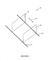
- Figure 4 illustrates one embodiment of a display device 70 comprising a single display unit and a pair of rails 72 as a frame.
- the single display can be translated along the rails 72 from a first position 74 to a second position 76 according to arrow 78.
- the display unit can take a plurality of positions along the rails 72.
- the displacement of the display unit can be motorized or manually performed.
- figure 5 illustrates one embodiment of a display device 80 comprising 8 display units 82-96.
- the display units 82-96 are transparent or see-through displays and they are mounted sequentially on a frame 98.
- the display units 82-96 may have a fixed or variable position with respect to the frame 98. Alternatively, some of the display units 82-96 may have a fixed position while others can move relative to the frame 98.
- the display device 80 is connected to a computer which generates a cross-sectional image 100-114 for each one of the display units 82-96, respectively, according to the position of each one of display units 82-96.
- the object is an ocean surface wave which is either simulated by the computer or generated by the computer using measured data.
- the computer stores the generated or measured model of the ocean surface wave in a memory.
- the computer generates a cross-sectional image 100-114 for each one of the display units 82-96 according to its position and transmits the generated images 100-114 to the display device 80 to be displayed on the corresponding display unit 82-96, respectively.
- the cross-sectional image 100 is generated according to the spatial position of the display unit 82 relative to the frame 98 and is displayed on the display unit 100.
- the transparency of the display units 82-96 allows a 3D visualization of the ocean surface wave.
- the display units 82-96 are transparent or partially transparent, a user looking at the display device 80 sees the image 100 displayed on the first display unit 82 and also what is behind the display unit 100, namely the images 102-114.
- the last display unit 96 is a non-transparent display unit displaying the cross-sectional image 114.
- the last display unit 96 may display a background image.
- the last display unit may be replaced by a mirror to give a depth perspective to a user looking at the display device 80.
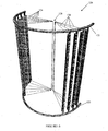
- FIG. 6 illustrates one embodiment of a semicircular display device 120.
- the display device 120 comprises a frame constituted of two semicircular rails 122 and ten transparent display units 124 and 126.
- the display units 124 and 126 may be non-transparent.
- the display units are divided into two sets, i.e. a first set of 6 display units 124 and a second set of four display units 126.
- the display units 124 have one end connected to the rails 122 and the other end connected together.
- the same arrangement also exists for the second set of display units 126.
- This configuration in which all of the display units 124 and 126 originate from a same origin 128 is referred to a star configuration.
- the display units 124 and 126 slide into the rails 122 so that the display units 124, 126 are displaceable within the display device 120.
- a cross-sectional image of an object is displayed on each one of the display units 124 and 126 according to the position of the corresponding display unit 124, 126.
- the displayed image changes to represent the corresponding cross-section of the object according to the new position of the display unit 124, 126.
- a mirror is placed behind the display device 120 to give the illusion of a complete object. In this case, only half of the object is displayed but a user has the illusion of seeing a complete 3D representation of the object.
- the rails 122 are circular and the display units 124, 126 are rotatable about an angle of 360 degrees within the display device 120.
- the rails 122 are circular and the display device 120 is provided with display units evenly distributed within the display device 120, which means that the angle formed by two consecutive display units is constant.
- the display units can be motorized and they rotate at a predetermined speed within the display device 120.
- a predetermined time interval corresponds to the predetermined rotation speed and to the number of display devices. For each spatial vertical plane within the display, an image is displayed at each predetermined time. At any time, the rotation of the display units may be stopped such that a particular display unit occupies a specific position selected by the user in order to display a desired cross-section of the object.
- Figure 7 illustrates one embodiment of a star display device 140 in which the frame comprises a display supporting piece 142 and two mirrors 144.
- the display supporting piece 142 has a quarter-cylindrical shape and is mounted between the two mirrors 144.
- Ten display units 146 are fixedly and immovably attached to the display supporting piece 142 at regular intervals. A cross-sectional image is displayed on each one of the display units 146 according to its position.
- the display units 146 are substantially transparent, the use of mirrors at the 0 and 90 degree positions gives the illusion of viewing a 3D representation of the entire object.
- the mirrors 144 may be omitted in the display device 140 and/or the display units 146 may be non-transparent.
- Figure 8 illustrates one embodiment of a two-stage display device 150 comprising two stages 152 and 154 one on top of the other.
- the display device 150 has a cylindrical shape in order to substantially mimic the shape of a cylindrical object of which a representation is displayed on the display device 150.
- the first stage 152 comprises a half-circular rail 156, two lateral rods 158, nine display supporting rods 160 and nine display units 162.
- the display supporting rods 160 are secured to the circular rail 156.
- the rail 156, the lateral rods 158, and the display supporting rods form a frame supporting the display units 162.
- Each display unit 162 is secured at one end to a corresponding display supporting rod 160.
- the second stage 154 comprises a half-circular rail 166, two lateral rods 168, ten display supporting rods 170 and ten display units 172.
- the display supporting rods 170 are secured to the rail 166, and the rail 166, the lateral rods 168 and the display supporting rods 170 form a frame for supporting the display units 172 which each have one end secured to a corresponding display supporting rod 170.
- Each display unit 162, 172 displays a representation of a cross-section of the cylindrical object in accordance with the spatial position in the 3D environment of the display unit 162, 172.
- Both the first stage 152 and the second stage 154 of the display device 150 have a star configuration and the display units 162 and 172 are angularly equally spaced.
- the ten display units 172 are spaced by a 20 degrees angle such that the first display unit 172 is at the 0 degree position and the tenth display unit 172 is at the 180 degree position.
- the display units 162 are positioned in the stage 152 such that one display unit 162 is angularly located between two following display units 172. In this embodiment, two successive display units 162 are angularly spaced by a 20 degree angle and the first display unit 162 is at the 10 degree position while the ninth display unit 162 is at the 170 degree position.
- the lateral rods 158 are slidably secured to the lateral rods 168, such that the lateral rods 158 can fit into the lateral rods 168, as illustrated in figure 9 .
- the rods 158 are inserted into the rods 168, and each display unit 162 is positioned between two successive display units 172.
- the display device 150 comprises nineteen display units angularly spaced by a 10 degree angle. It should be understood that the number of display units 162 and 172 and the angular spacing between the display units 162 and 172 are exemplary only.
- the size of the display device 150 is adjustable in accordance with the object to be represented thereon.
- a representation of a first cylindrical object having a first height can be displayed on the display device 150 when in the close position.
- a representation of a second cylindrical object having a second height longer than the first height can be displayed on the display device 150 when in the open position.
- an enlarged representation of an object may be displayed when the display device 150 is in the open position.
- the display supporting rods 160 and 170 are fixedly secured to the rails 156 and 166, respectively, and immobile within the first and second stages 152 and 154, respectively.
- the display supporting rods 160 and 170 slide into the rails 156 and 166, respectively, so that the display units 162 and 172 are displaceable within the stage 152 and 154, respectively.
- the display units 162 and 172 are also displaceable when the display device 150 is in the close position.
- the display supporting rods 160 and 170 are rotatably secured to the rails 156 and 166, respectively, such that the display units 162 and 172 can be moved in the directions of arrows A and B, respectively, illustrated in figure 8 .
- the display device 120, 140, 150 is connected to a computer comprising a processor, communication means and a memory on which the model of the object is stored. Any positioning system for determining the position of the display unit 124, 126, 146, 162, 172 can be used.
- the processor is configured for generating, for each display unit 124, 126, 146, 162, 172, the cross-section of the object in accordance with the position of the display unit 124, 126, 146, 162, 172.
- the frame of the display device 120, 150 is motorized in order to move the display unit 124, 126, 162, 172.
- the motors are connected to the communication means of the computer and the position of the motors is controlled via the computer.
- the motors are adapted to communicate their respective positions to the computer which determines the position of the display units 124, 126, 162, 172 in accordance with the position of the motors.
- the transparent or non-transparent display unit may be a touchscreen.
- the display unit detects the location of a physical contact within its display area and the display unit itself is used as an input device for interacting with the computer.
- touch is associated with a predetermined command such as a zoom command.
- a menu may appear when touching the display unit. The user selects a command to be executed by the computer from the displayed menu.
- the display device Upon reception of the command by touching the display unit, the display device sends the command to the computer.
- the processor of the computer executes the command and generates a new image to be displayed on the display unit or moves the display unit to a new position, for example.
- the present description refers to a computer in order to simulate an object or to create an object using measured data
- any system or terminal being adapted to perform these tasks can be used.
- the sensors measuring the data may be adapted to create the appropriate image to be displayed on the display unit and to send it directly to the display unit.
- display units having different shapes and sizes can be used.
- the shapes and sizes of the display units may be chosen so that the shape of the display device substantially mimics the shape of the object to be represented, for example.
- any transparent or semi-transparent display unit can be used for the display device.
- the number of display units comprised in the display device may depend on the transparency of the display units. While in some instances, a high degree of transparency may be required, a low transparency may be desired for other applications.
- the present display device may have application in many fields.
- a display device such as the display device 80 could replace a usual television in order to display a movie in 3 dimensions.
- the object to be displayed in a 3D video frame of the movie and the cross-sectional images are different images which form the 3D video frame when overlaid.
- a colored screen such as a white screen can be placed behind the transparent display units.
- Figure 10 illustrates one embodiment of a method 180 for displaying a representation of an object.
- the fist step 182 consists in providing a plurality of display units.
- the next step 184 is the generation of an image for each one of the plurality of display units.
- Each image is a cross-sectional representation of the object according to the spatial position in the three-dimensional environment of the respective display unit on which the image is to be displayed.
- the last step 186 consists in displaying the generated images on their respective display unit for each one of said at least one display unit.
- a user moves a display unit from an initial position to a desired position.
- the displacement of the display unit can be done manually.
- the display device is motorized and the position of the display unit is controlled by the computer, the user enters the desired position for the display unit in the computer which displaces the display unit to the desired position.
- the computer generates the cross-sectional image of the object in accordance with the desired position for the display unit and the cross-sectional image is displayed on the display unit.
- the user selects a cross-section view of the object using the computer.
- the processor generates the cross-sectional image corresponding to the selected cross-section and determines the target position for the display unit in accordance with the selected cross-section.
- the computer then moves the display unit to the desired position and displays the cross-sectional image on the display unit.
- a display device is used to visualize in real time the data of a nuclear reactor core simulation model.
- the display device can have a cylindrical shape to mimic the shape of the core reactor. Data such as fluid flow, core heat diffusion and reactivity parameters may be displayed on the display device.
- the two display devices are cylindrical and comprise a plurality of display units which rotate while displaying the data images.
- the nuclear reactor core display device comprises two display devices such as display device 140. For example, the symmetry of the nuclear core model is exploited so that only a 90 (or 60) degrees section of the reactor core is displayed. The use of mirrors at the 0 and 90 (or 60) degree positions gives the illusion of viewing the entire reactor core.
- This embodiment can be used for reactor core thermal-hydraulics and neutronics models such as RELAP 3D (a widely used core simulation package) since the actual simulated model only computes data for a 60 or 90 degree section, depending on core design symmetry.
- the first display device is provided with 15 transparent display units spaced by 6 degrees intervals and the second display device is provided with 9 display units spaced by 10 degrees intervals.
- a display device can also be used for displaying information about reactor pressure vessel, containment building, pressurizer or steam generator. It can also be used for the real-time monitoring of the internal parameters associated with these areas of interest. It should be understood that any data related to a simulated or measured property of a pressure vessel may be displayed using a display device.
- a display device may be used for the real-time visualization of activity or area of interest, either originating from a model or from measured data. Fluid, gas and solid mechanics may also be displayed on a display device.
- a display device can be used to display any kind of activity taking place inside a particular area of interest.
- a display device is associated with a radar or a sonar to display the location of a vessel, an aircraft, a submarine and the like in 3 dimensions. It can also display a map of a battlefield in real time for immediate tactical and strategic adjustments.
- a display device can be used for a real-time visualization of complex orbital trajectories of a plurality of artificial satellites and real-time tracking of multiple threat matrices.
- a display device can also have application in the financial field. For example, it can be used to display a real-time view of simultaneous market indicators or key decision-making factors. It can also be used to extrapolate observed trends or visually detect the emergence of patterns.
- a display device has also application in operations research such as for the visualization of complex multidimensional solution spaces for cost optimization applications (linear programming, genetic algorithms, large project management, etc.).
- a display device can be used to display a real-time view of an organ such as a brain or a heart or a representation of a simulated organ. For example, the behaviour of an artificial neural network may be studied while being displayed on the display device.
- the display device may be used in other fields of activity than those cited in the present description.
- multiple users are able to view the same and different information simultaneously due to the true three-dimensional nature of the device.
Landscapes
- Engineering & Computer Science (AREA)
- Physics & Mathematics (AREA)
- Computer Hardware Design (AREA)
- General Physics & Mathematics (AREA)
- Theoretical Computer Science (AREA)
- Multimedia (AREA)
- Signal Processing (AREA)
- Processing Or Creating Images (AREA)
- Testing, Inspecting, Measuring Of Stereoscopic Televisions And Televisions (AREA)
Claims (15)
- Anzeigegerät (120, 140, 150) zum Anzeigen von Querschnitt-Darstellungen eines Gegenstandes, dadurch gekennzeichnet, dass das besagte Anzeigegerät (120, 140, 150) folgendes umfasst:einen Rahmen (12, 60, 98); undeine Vielzahl von Anzeigeeinheiten (124, 126, 146, 162, 172), die am besagten Rahmen montiert, und an einem Ende miteinander verbunden sind, wobei jede Einheit der besagten Vielzahl von Anzeigeeinheiten (124, 126, 146, 162, 172) eine geometrische Fläche definiert und sich dazu eignet, ein Schnittbild des besagten Gegenstandes anzuzeigen, wobei das besagte Schnittbild zumindest ein internes Merkmal des besagten Gegenstandes umfasst und von einer räumlichen Position in einer dreidimensionalen Umgebung einer entsprechenden Einheit der Vielzahl von Anzeigeeinheiten (124, 126, 146, 162, 172) abhängig ist, auf der das besagte Schnittbild anzuzeigen ist, wobei die besagte Vielzahl von Anzeigeeinheiten (124, 126, 146, 162, 172) mit einem Prozessor verbunden werden kann, der sich dazu eignet, das besagte Schnittbild für jede Einheit der besagten Vielzahl von Anzeigeeinheiten (124, 126, 146, 162, 172) in Abhängigkeit von der besagten räumlichen Position zu erzeugen, wobei der besagte Rahmen und die besagte Vielzahl von Anzeigeeinheiten (124, 126, 146, 162, 172) eine zylindrische Form aufweisen, um im Wesentlichen eine Form eines zylindrischen Gegenstandes nachzuahmen, dessen Darstellung auf dem Anzeigegerät (120, 140, 150) dargestellt wird, und sich die Vielzahl von Anzeigeeinheiten (124, 126, 146, 162, 172) dazu eignen, sich in Bezug auf den Rahmen zu bewegen, während sie auf dem Rahmen gehalten oder darauf befestigt bleiben.
- Anzeigegerät (120, 140, 150) nach Anspruch 1, wobei jede Einheit der besagten Vielzahl von Anzeigeeinheiten eine fixe Position im Verhältnis zum besagten Rahmen aufweist.
- Anzeigegerät (120, 140, 150) nach Anspruch 1, wobei zumindest eine Einheit der besagten Vielzahl von Anzeigeeinheiten eine variable Position im Verhältnis zum besagten Rahmen aufweist.
- Anzeigegerät (120, 140, 150) nach Anspruch 1, wobei zumindest eine Einheit der besagten Vielzahl von Anzeigeeinheiten (124, 126, 146) transparent ist.
- Anzeigegerät (120, 140, 150) nach Anspruch 4, das darüber hinaus zumindest einen Spiegel (144) umfasst, der hinter der besagten Vielzahl von Anzeigeeinheiten (124, 126, 146, 162, 172) angeordnet ist.
- Anzeigegerät (120, 140, 150) nach Anspruch 1, das darüber hinaus zumindest einen Motor umfasst, der sich dazu eignet, die besagte Vielzahl von Anzeigeeinheiten (124, 126, 146, 162, 172) zu bewegen, und dem besagten Prozessor die besagte räumliche Position für jede Einheit der besagten Vielzahl von Anzeigeeinheiten (124, 126, 146, 162, 172) mitzuteilen, wobei der besagte zumindest eine Motor vom besagten Prozessor gesteuert werden kann.
- Anzeigegerät (120, 140, 150) nach Anspruch 1, wobei die besagte Vielzahl von Anzeigeeinheiten (124, 126, 162, 172) innerhalb des besagten Rahmens in einer Sternkonfiguration angeordnet ist.
- Anzeigegerät (120, 140, 150) nach Anspruch 1, wobei das besagte zumindest eine interne Merkmal zeitabhängig ist, und sich jede Einheit der besagten Vielzahl von Anzeigeeinheiten (124, 126, 146, 162, 172) dazu eignet, das besagte Schnittbild im Wesentlichen in Echtzeit anzuzeigen.
- Anzeigegerät (120, 140, 150) nach Anspruch 1, wobei das besagte Schnittbild einen Querschnitt eines Reaktorkerns darstellt, und zumindest ein internes Merkmal zumindest eines aus einer Fluidströmung, einer Wärmediffusion und einem Reaktivitätsparameter umfasst.
- Verfahren zum Anzeigen von Querschnitt-Darstellungen eines Gegenstandes, dadurch gekennzeichnet, dass das besagte Verfahren folgendes umfasst:Empfangen eines Bildes für jede Einheit der Vielzahl von Anzeigeeinheiten (124, 126, 146, 162, 172), die eine geometrische Fläche bilden, wobei das besagte Bild zumindest ein internes Merkmal des besagten Gegenstandes umfasst und eine Querschnitt-Darstellung des besagten Gegenstandes entsprechend einer räumlichen Position in einer dreidimensionalen Umgebung einer entsprechenden Anzeigeeinheit ist, auf der das besagte Bild anzuzeigen ist;Anzeigen des besagten Bildes auf der besagten entsprechenden Anzeigeeinheit für jede Einheit der besagten Vielzahl von Anzeigeeinheiten (124, 126, 146, 162, 172);Bewegen einer Einheit der besagten Vielzahl von Anzeigeeinheiten (124, 126, 146, 162, 172) in eine andere Position;Empfangen eines anderen Schnittbildes des besagten Gegenstandes in Übereinstimmung mit der besagten anderen Position; undAnzeigen des besagten anderen Schnittbildes auf der besagten einen Einheit der besagten Vielzahl von Anzeigeeinheiten (124, 126, 146, 162, 172).
- Verfahren nach Anspruch 10, das darüber hinaus den Empfang von Koordinaten für eine Zielposition für eine Einheit der besagten Vielzahl von Anzeigeeinheiten (124, 126, 146, 162, 172) in Übereinstimmung mit einer ausgewählten Schnittansicht des besagten Gegenstandes umfasst.
- Verfahren nach Anspruch 11, wobei die besagte Bewegung automatisch das Verschieben der besagten einen Einheit der besagten Vielzahl von Anzeigeeinheiten (124, 126, 146, 162, 172) in die besagte Zielposition umfasst.
- Verfahren nach Anspruch 10, wobei die besagte Anzeige des besagten Bildes die Anzeige der besagten Bildes auf einer entsprechenden transparenten Anzeigeeinheit für jede Einheit der besagten Vielzahl von Anzeigeeinheiten (124, 126, 146) umfasst.
- Verfahren nach Anspruch 10, wobei die besagte Anzeige des besagten Bildes die Anzeige eines zeitabhängigen Bildes im Wesentlichen in Echtzeit umfasst.
- Verfahren nach Anspruch 10, wobei der besagte Empfang des besagten Bildes den Empfang des besagten Bildes umfasst, das einen Querschnitt eines Reaktorkerns darstellt, und wobei das besagte zumindest eine interne Merkmal zumindest eines aus einer Fluidströmung, einer Wärmediffusion und einem Reaktivitätsparameter umfasst.
Applications Claiming Priority (2)
| Application Number | Priority Date | Filing Date | Title |
|---|---|---|---|
| US5602808P | 2008-05-26 | 2008-05-26 | |
| PCT/CA2009/000709 WO2009143607A1 (en) | 2008-05-26 | 2009-05-25 | Display device for displaying cross -sectional representations of an object |
Publications (3)
| Publication Number | Publication Date |
|---|---|
| EP2294569A1 EP2294569A1 (de) | 2011-03-16 |
| EP2294569A4 EP2294569A4 (de) | 2012-09-19 |
| EP2294569B1 true EP2294569B1 (de) | 2015-07-29 |
Family
ID=41376505
Family Applications (1)
| Application Number | Title | Priority Date | Filing Date |
|---|---|---|---|
| EP09753368.1A Not-in-force EP2294569B1 (de) | 2008-05-26 | 2009-05-25 | Anzeigeanordnung zum anzeigen von querschnittdarstellungen eines objekts |
Country Status (4)
| Country | Link |
|---|---|
| US (1) | US8587640B2 (de) |
| EP (1) | EP2294569B1 (de) |
| CA (1) | CA2763528C (de) |
| WO (1) | WO2009143607A1 (de) |
Families Citing this family (6)
| Publication number | Priority date | Publication date | Assignee | Title |
|---|---|---|---|---|
| US10319484B1 (en) | 2011-11-17 | 2019-06-11 | Nuscale Power, Llc | Method for imaging a nuclear reactor |
| US9424376B2 (en) * | 2011-11-18 | 2016-08-23 | Terrapower, Llc | Enhanced neutronics systems |
| WO2020056388A1 (en) * | 2018-09-13 | 2020-03-19 | Board Of Regents Of The University Of Nebraska | Simulating heat flux in additive manufacturing |
| CN110910802B (zh) * | 2019-11-25 | 2023-06-09 | 北京京东方光电科技有限公司 | 全息显示方法、装置及可读存储介质 |
| US12373616B2 (en) | 2020-10-12 | 2025-07-29 | Nutech Ventures | Thermal modeling of additive manufacturing using graph theory |
| JP7567582B2 (ja) * | 2021-03-15 | 2024-10-16 | 株式会社Jvcケンウッド | 立体映像表示装置、立体映像表示方法およびプログラム |
Family Cites Families (22)
| Publication number | Priority date | Publication date | Assignee | Title |
|---|---|---|---|---|
| FR2390725A1 (fr) * | 1977-05-13 | 1978-12-08 | Commissariat Energie Atomique | Dispositif de photometrie a miroirs concaves et a optique de champ |
| US4712869A (en) * | 1986-10-24 | 1987-12-15 | Claxton John C | Three dimensional stacked reproduction screen |
| US5023895A (en) * | 1989-03-02 | 1991-06-11 | Innovative Imaging Systems, Inc. | Three dimensional tomographic system |
| KR100188712B1 (ko) * | 1996-11-28 | 1999-06-01 | 이종구 | 단층 영상장치 및 이를 이용한 단층영상 획득방법 |
| US6525699B1 (en) * | 1998-05-21 | 2003-02-25 | Nippon Telegraph And Telephone Corporation | Three-dimensional representation method and an apparatus thereof |
| US6275718B1 (en) * | 1999-03-23 | 2001-08-14 | Philip Lempert | Method and apparatus for imaging and analysis of ocular tissue |
| US6404437B1 (en) * | 1999-09-10 | 2002-06-11 | General Electric Company | Nuclear reactor core performance data visualization system |
| JP2001337391A (ja) * | 2000-05-26 | 2001-12-07 | Minolta Co Ltd | 投影装置および斜め投影光学系 |
| US6860602B2 (en) * | 2001-10-02 | 2005-03-01 | Nidek Co., Ltd. | Apparatus for examining an anterior-segment of an eye |
| JP3650063B2 (ja) * | 2001-12-26 | 2005-05-18 | 核燃料サイクル開発機構 | 伝熱管検査装置 |
| US7200541B2 (en) * | 2002-12-23 | 2007-04-03 | Global Nuclear Fuel-Americas, Llc | Method and arrangement for determining nuclear reactor core designs |
| KR200315584Y1 (ko) * | 2003-02-13 | 2003-06-09 | 삼성전자주식회사 | 투사장치의 광학계 |
| US20050073471A1 (en) | 2003-10-03 | 2005-04-07 | Uni-Pixel Displays, Inc. | Z-axis redundant display/multilayer display |
| US7444011B2 (en) * | 2004-02-10 | 2008-10-28 | University Of Chicago | Imaging system performing substantially exact reconstruction and using non-traditional trajectories |
| KR101235273B1 (ko) * | 2005-07-07 | 2013-02-20 | 삼성전자주식회사 | 다수의 투명한 플렉시블 디스플레이 패널을 이용한 체적형3차원 디스플레이 시스템 |
| KR100657338B1 (ko) * | 2005-09-26 | 2006-12-14 | 삼성전자주식회사 | 투사형 화상표시장치 |
| JP4605507B2 (ja) * | 2005-12-14 | 2011-01-05 | 富士電機デバイステクノロジー株式会社 | 三次元立体像の表示装置 |
| US8380321B2 (en) * | 2006-02-24 | 2013-02-19 | Medtronic, Inc. | Programming interface with a cross-sectional view of a stimulation lead with complex electrode array geometry |
| US8147414B2 (en) * | 2006-10-12 | 2012-04-03 | Innoscion, Llc | Image guided catheter having remotely controlled surfaces-mounted and internal ultrasound transducers |
| WO2008137710A1 (en) * | 2007-05-03 | 2008-11-13 | University Of Washington | High resolution optical coherence tomography based imaging for intraluminal and interstitial use implemented with a reduced form factor |
| JP4691581B2 (ja) * | 2008-06-13 | 2011-06-01 | 日立Geニュークリア・エナジー株式会社 | 水中移動体の位置検知装置 |
| TWI408338B (zh) * | 2009-08-11 | 2013-09-11 | Univ Nat Taiwan | 干涉量測裝置及其量測方法 |
-
2009
- 2009-05-25 US US12/994,804 patent/US8587640B2/en not_active Expired - Fee Related
- 2009-05-25 CA CA2763528A patent/CA2763528C/en active Active
- 2009-05-25 EP EP09753368.1A patent/EP2294569B1/de not_active Not-in-force
- 2009-05-25 WO PCT/CA2009/000709 patent/WO2009143607A1/en not_active Ceased
Also Published As
| Publication number | Publication date |
|---|---|
| US8587640B2 (en) | 2013-11-19 |
| CA2763528C (en) | 2015-10-27 |
| US20110074936A1 (en) | 2011-03-31 |
| CA2763528A1 (en) | 2009-12-03 |
| EP2294569A4 (de) | 2012-09-19 |
| WO2009143607A1 (en) | 2009-12-03 |
| EP2294569A1 (de) | 2011-03-16 |
Similar Documents
| Publication | Publication Date | Title |
|---|---|---|
| EP2294569B1 (de) | Anzeigeanordnung zum anzeigen von querschnittdarstellungen eines objekts | |
| KR100327874B1 (ko) | 헤드트랙된입체디스플레이시스템에서고분해능3차원영상을발생하는방법및장치 | |
| Bane et al. | Interactive Tools for Virtual X-Ray Vision in Mobile Augmented Reality. | |
| US20180314322A1 (en) | System and method for immersive cave application | |
| CN100356300C (zh) | 虚拟现实呈现装置和信息处理方法 | |
| KR101229283B1 (ko) | 가상 3차원 객체들의 시각화를 위한 방법 및 시스템 | |
| US20040233192A1 (en) | Focally-controlled imaging system and method | |
| EP3293703B1 (de) | Virtuelle fenstervorrichtung und verfahren zum betrieb einer virtuellen fenstervorrichtung | |
| EP4100797A1 (de) | »pop-out - und »sink-in -freiraumhologrammvorrichtung zur erstellung, generierung, anzeige und gemeinsamen nutzung von hochauflösenden »pop-out - und »sink-in -freiraumhologrammen mit »pop-out - und »sink-in -holografischer erweiterter realität (ar), virtueller realität (vr) und gemischter realität (mr) | |
| US20200110560A1 (en) | Systems and methods for interfacing with a non-human entity based on user interaction with an augmented reality environment | |
| CN105093551B (zh) | 景观环境实时表现中的真三维立体显示系统及显示方法 | |
| US20160205385A1 (en) | Holoscope digital virtual object projector | |
| US20140160122A1 (en) | Creating a virtual representation based on camera data | |
| US20180048883A1 (en) | Image display apparatus and image display method | |
| Thomas et al. | Spatial augmented reality—A tool for 3D data visualization | |
| JP7141833B2 (ja) | 画像処理装置および画像処理プログラム | |
| CN104898653B (zh) | 一种飞行控制系统 | |
| Yasugi et al. | Development of aerial interface by integrating omnidirectional aerial display, motion tracking, and virtual reality space construction | |
| Singla | Virtual reality based novel use case in remote sensing and GIS | |
| JP4744536B2 (ja) | 情報提示装置 | |
| US20070188862A1 (en) | Multifocal lens array and three-dimensional stereoscopic image display apparatus | |
| CN103019023B (zh) | 基于体视技术的全视角三维显示系统和方法 | |
| CN113168228A (zh) | 用于在大面积透明触摸界面中进行视差校正的系统和/或方法 | |
| Krumbholz et al. | Lambda table: high resolution tiled display table for interacting with large visualizations | |
| Qi et al. | Tangible user interfaces for 3D clipping plane interaction with volumetric data: a case study |
Legal Events
| Date | Code | Title | Description |
|---|---|---|---|
| PUAI | Public reference made under article 153(3) epc to a published international application that has entered the european phase |
Free format text: ORIGINAL CODE: 0009012 |
|
| 17P | Request for examination filed |
Effective date: 20101220 |
|
| AK | Designated contracting states |
Kind code of ref document: A1 Designated state(s): AT BE BG CH CY CZ DE DK EE ES FI FR GB GR HR HU IE IS IT LI LT LU LV MC MK MT NL NO PL PT RO SE SI SK TR |
|
| AX | Request for extension of the european patent |
Extension state: AL BA RS |
|
| DAX | Request for extension of the european patent (deleted) | ||
| A4 | Supplementary search report drawn up and despatched |
Effective date: 20120817 |
|
| RIC1 | Information provided on ipc code assigned before grant |
Ipc: G09G 5/12 20060101ALI20120810BHEP Ipc: G09F 9/30 20060101ALI20120810BHEP Ipc: G09G 5/00 20060101AFI20120810BHEP |
|
| GRAP | Despatch of communication of intention to grant a patent |
Free format text: ORIGINAL CODE: EPIDOSNIGR1 |
|
| INTG | Intention to grant announced |
Effective date: 20150206 |
|
| GRAS | Grant fee paid |
Free format text: ORIGINAL CODE: EPIDOSNIGR3 |
|
| GRAA | (expected) grant |
Free format text: ORIGINAL CODE: 0009210 |
|
| AK | Designated contracting states |
Kind code of ref document: B1 Designated state(s): AT BE BG CH CY CZ DE DK EE ES FI FR GB GR HR HU IE IS IT LI LT LU LV MC MK MT NL NO PL PT RO SE SI SK TR |
|
| REG | Reference to a national code |
Ref country code: GB Ref legal event code: FG4D |
|
| REG | Reference to a national code |
Ref country code: CH Ref legal event code: EP |
|
| REG | Reference to a national code |
Ref country code: AT Ref legal event code: REF Ref document number: 739839 Country of ref document: AT Kind code of ref document: T Effective date: 20150815 |
|
| REG | Reference to a national code |
Ref country code: IE Ref legal event code: FG4D |
|
| REG | Reference to a national code |
Ref country code: DE Ref legal event code: R096 Ref document number: 602009032528 Country of ref document: DE |
|
| REG | Reference to a national code |
Ref country code: AT Ref legal event code: MK05 Ref document number: 739839 Country of ref document: AT Kind code of ref document: T Effective date: 20150729 |
|
| REG | Reference to a national code |
Ref country code: LT Ref legal event code: MG4D |
|
| REG | Reference to a national code |
Ref country code: NL Ref legal event code: MP Effective date: 20150729 |
|
| PG25 | Lapsed in a contracting state [announced via postgrant information from national office to epo] |
Ref country code: NO Free format text: LAPSE BECAUSE OF FAILURE TO SUBMIT A TRANSLATION OF THE DESCRIPTION OR TO PAY THE FEE WITHIN THE PRESCRIBED TIME-LIMIT Effective date: 20151029 Ref country code: LV Free format text: LAPSE BECAUSE OF FAILURE TO SUBMIT A TRANSLATION OF THE DESCRIPTION OR TO PAY THE FEE WITHIN THE PRESCRIBED TIME-LIMIT Effective date: 20150729 Ref country code: GR Free format text: LAPSE BECAUSE OF FAILURE TO SUBMIT A TRANSLATION OF THE DESCRIPTION OR TO PAY THE FEE WITHIN THE PRESCRIBED TIME-LIMIT Effective date: 20151030 Ref country code: LT Free format text: LAPSE BECAUSE OF FAILURE TO SUBMIT A TRANSLATION OF THE DESCRIPTION OR TO PAY THE FEE WITHIN THE PRESCRIBED TIME-LIMIT Effective date: 20150729 Ref country code: FI Free format text: LAPSE BECAUSE OF FAILURE TO SUBMIT A TRANSLATION OF THE DESCRIPTION OR TO PAY THE FEE WITHIN THE PRESCRIBED TIME-LIMIT Effective date: 20150729 |
|
| PG25 | Lapsed in a contracting state [announced via postgrant information from national office to epo] |
Ref country code: PT Free format text: LAPSE BECAUSE OF FAILURE TO SUBMIT A TRANSLATION OF THE DESCRIPTION OR TO PAY THE FEE WITHIN THE PRESCRIBED TIME-LIMIT Effective date: 20151130 Ref country code: SE Free format text: LAPSE BECAUSE OF FAILURE TO SUBMIT A TRANSLATION OF THE DESCRIPTION OR TO PAY THE FEE WITHIN THE PRESCRIBED TIME-LIMIT Effective date: 20150729 Ref country code: HR Free format text: LAPSE BECAUSE OF FAILURE TO SUBMIT A TRANSLATION OF THE DESCRIPTION OR TO PAY THE FEE WITHIN THE PRESCRIBED TIME-LIMIT Effective date: 20150729 Ref country code: ES Free format text: LAPSE BECAUSE OF FAILURE TO SUBMIT A TRANSLATION OF THE DESCRIPTION OR TO PAY THE FEE WITHIN THE PRESCRIBED TIME-LIMIT Effective date: 20150729 Ref country code: IS Free format text: LAPSE BECAUSE OF FAILURE TO SUBMIT A TRANSLATION OF THE DESCRIPTION OR TO PAY THE FEE WITHIN THE PRESCRIBED TIME-LIMIT Effective date: 20151129 Ref country code: PL Free format text: LAPSE BECAUSE OF FAILURE TO SUBMIT A TRANSLATION OF THE DESCRIPTION OR TO PAY THE FEE WITHIN THE PRESCRIBED TIME-LIMIT Effective date: 20150729 Ref country code: AT Free format text: LAPSE BECAUSE OF FAILURE TO SUBMIT A TRANSLATION OF THE DESCRIPTION OR TO PAY THE FEE WITHIN THE PRESCRIBED TIME-LIMIT Effective date: 20150729 |
|
| PG25 | Lapsed in a contracting state [announced via postgrant information from national office to epo] |
Ref country code: NL Free format text: LAPSE BECAUSE OF FAILURE TO SUBMIT A TRANSLATION OF THE DESCRIPTION OR TO PAY THE FEE WITHIN THE PRESCRIBED TIME-LIMIT Effective date: 20150729 |
|
| PG25 | Lapsed in a contracting state [announced via postgrant information from national office to epo] |
Ref country code: IT Free format text: LAPSE BECAUSE OF FAILURE TO SUBMIT A TRANSLATION OF THE DESCRIPTION OR TO PAY THE FEE WITHIN THE PRESCRIBED TIME-LIMIT Effective date: 20150729 Ref country code: EE Free format text: LAPSE BECAUSE OF FAILURE TO SUBMIT A TRANSLATION OF THE DESCRIPTION OR TO PAY THE FEE WITHIN THE PRESCRIBED TIME-LIMIT Effective date: 20150729 Ref country code: SK Free format text: LAPSE BECAUSE OF FAILURE TO SUBMIT A TRANSLATION OF THE DESCRIPTION OR TO PAY THE FEE WITHIN THE PRESCRIBED TIME-LIMIT Effective date: 20150729 Ref country code: DK Free format text: LAPSE BECAUSE OF FAILURE TO SUBMIT A TRANSLATION OF THE DESCRIPTION OR TO PAY THE FEE WITHIN THE PRESCRIBED TIME-LIMIT Effective date: 20150729 Ref country code: CZ Free format text: LAPSE BECAUSE OF FAILURE TO SUBMIT A TRANSLATION OF THE DESCRIPTION OR TO PAY THE FEE WITHIN THE PRESCRIBED TIME-LIMIT Effective date: 20150729 |
|
| REG | Reference to a national code |
Ref country code: DE Ref legal event code: R097 Ref document number: 602009032528 Country of ref document: DE |
|
| REG | Reference to a national code |
Ref country code: FR Ref legal event code: PLFP Year of fee payment: 8 |
|
| PG25 | Lapsed in a contracting state [announced via postgrant information from national office to epo] |
Ref country code: RO Free format text: LAPSE BECAUSE OF FAILURE TO SUBMIT A TRANSLATION OF THE DESCRIPTION OR TO PAY THE FEE WITHIN THE PRESCRIBED TIME-LIMIT Effective date: 20150729 |
|
| PLBE | No opposition filed within time limit |
Free format text: ORIGINAL CODE: 0009261 |
|
| STAA | Information on the status of an ep patent application or granted ep patent |
Free format text: STATUS: NO OPPOSITION FILED WITHIN TIME LIMIT |
|
| 26N | No opposition filed |
Effective date: 20160502 |
|
| PG25 | Lapsed in a contracting state [announced via postgrant information from national office to epo] |
Ref country code: SI Free format text: LAPSE BECAUSE OF FAILURE TO SUBMIT A TRANSLATION OF THE DESCRIPTION OR TO PAY THE FEE WITHIN THE PRESCRIBED TIME-LIMIT Effective date: 20150729 Ref country code: BE Free format text: LAPSE BECAUSE OF NON-PAYMENT OF DUE FEES Effective date: 20160531 |
|
| PG25 | Lapsed in a contracting state [announced via postgrant information from national office to epo] |
Ref country code: LU Free format text: LAPSE BECAUSE OF FAILURE TO SUBMIT A TRANSLATION OF THE DESCRIPTION OR TO PAY THE FEE WITHIN THE PRESCRIBED TIME-LIMIT Effective date: 20160525 Ref country code: BE Free format text: LAPSE BECAUSE OF FAILURE TO SUBMIT A TRANSLATION OF THE DESCRIPTION OR TO PAY THE FEE WITHIN THE PRESCRIBED TIME-LIMIT Effective date: 20150729 |
|
| REG | Reference to a national code |
Ref country code: CH Ref legal event code: PL |
|
| GBPC | Gb: european patent ceased through non-payment of renewal fee |
Effective date: 20160525 |
|
| PG25 | Lapsed in a contracting state [announced via postgrant information from national office to epo] |
Ref country code: CH Free format text: LAPSE BECAUSE OF NON-PAYMENT OF DUE FEES Effective date: 20160531 Ref country code: LI Free format text: LAPSE BECAUSE OF NON-PAYMENT OF DUE FEES Effective date: 20160531 |
|
| REG | Reference to a national code |
Ref country code: IE Ref legal event code: MM4A |
|
| PG25 | Lapsed in a contracting state [announced via postgrant information from national office to epo] |
Ref country code: IE Free format text: LAPSE BECAUSE OF NON-PAYMENT OF DUE FEES Effective date: 20160525 Ref country code: GB Free format text: LAPSE BECAUSE OF NON-PAYMENT OF DUE FEES Effective date: 20160525 |
|
| REG | Reference to a national code |
Ref country code: FR Ref legal event code: PLFP Year of fee payment: 9 |
|
| REG | Reference to a national code |
Ref country code: FR Ref legal event code: PLFP Year of fee payment: 10 |
|
| PG25 | Lapsed in a contracting state [announced via postgrant information from national office to epo] |
Ref country code: HU Free format text: LAPSE BECAUSE OF FAILURE TO SUBMIT A TRANSLATION OF THE DESCRIPTION OR TO PAY THE FEE WITHIN THE PRESCRIBED TIME-LIMIT; INVALID AB INITIO Effective date: 20090525 Ref country code: CY Free format text: LAPSE BECAUSE OF FAILURE TO SUBMIT A TRANSLATION OF THE DESCRIPTION OR TO PAY THE FEE WITHIN THE PRESCRIBED TIME-LIMIT Effective date: 20150729 |
|
| PG25 | Lapsed in a contracting state [announced via postgrant information from national office to epo] |
Ref country code: TR Free format text: LAPSE BECAUSE OF FAILURE TO SUBMIT A TRANSLATION OF THE DESCRIPTION OR TO PAY THE FEE WITHIN THE PRESCRIBED TIME-LIMIT Effective date: 20150729 Ref country code: MK Free format text: LAPSE BECAUSE OF FAILURE TO SUBMIT A TRANSLATION OF THE DESCRIPTION OR TO PAY THE FEE WITHIN THE PRESCRIBED TIME-LIMIT Effective date: 20150729 Ref country code: MT Free format text: LAPSE BECAUSE OF NON-PAYMENT OF DUE FEES Effective date: 20160531 Ref country code: MC Free format text: LAPSE BECAUSE OF FAILURE TO SUBMIT A TRANSLATION OF THE DESCRIPTION OR TO PAY THE FEE WITHIN THE PRESCRIBED TIME-LIMIT Effective date: 20150729 |
|
| PG25 | Lapsed in a contracting state [announced via postgrant information from national office to epo] |
Ref country code: BG Free format text: LAPSE BECAUSE OF FAILURE TO SUBMIT A TRANSLATION OF THE DESCRIPTION OR TO PAY THE FEE WITHIN THE PRESCRIBED TIME-LIMIT Effective date: 20150729 |
|
| PGFP | Annual fee paid to national office [announced via postgrant information from national office to epo] |
Ref country code: DE Payment date: 20180530 Year of fee payment: 10 |
|
| REG | Reference to a national code |
Ref country code: DE Ref legal event code: R119 Ref document number: 602009032528 Country of ref document: DE |
|
| PG25 | Lapsed in a contracting state [announced via postgrant information from national office to epo] |
Ref country code: DE Free format text: LAPSE BECAUSE OF NON-PAYMENT OF DUE FEES Effective date: 20191203 |
|
| PGFP | Annual fee paid to national office [announced via postgrant information from national office to epo] |
Ref country code: FR Payment date: 20220530 Year of fee payment: 14 |
|
| PG25 | Lapsed in a contracting state [announced via postgrant information from national office to epo] |
Ref country code: FR Free format text: LAPSE BECAUSE OF NON-PAYMENT OF DUE FEES Effective date: 20230531 |