EP2294441B1 - Method of detecting an object in a scene comprising artefacts - Google Patents
Method of detecting an object in a scene comprising artefacts Download PDFInfo
- Publication number
- EP2294441B1 EP2294441B1 EP09793898A EP09793898A EP2294441B1 EP 2294441 B1 EP2294441 B1 EP 2294441B1 EP 09793898 A EP09793898 A EP 09793898A EP 09793898 A EP09793898 A EP 09793898A EP 2294441 B1 EP2294441 B1 EP 2294441B1
- Authority
- EP
- European Patent Office
- Prior art keywords
- images
- pixel
- image
- pixels
- sector
- Prior art date
- Legal status (The legal status is an assumption and is not a legal conclusion. Google has not performed a legal analysis and makes no representation as to the accuracy of the status listed.)
- Active
Links
- 238000000034 method Methods 0.000 title claims abstract description 34
- 238000012790 confirmation Methods 0.000 claims abstract description 38
- 238000001514 detection method Methods 0.000 claims abstract description 22
- 239000011159 matrix material Substances 0.000 claims abstract description 12
- 238000012545 processing Methods 0.000 claims abstract description 10
- 238000009825 accumulation Methods 0.000 claims description 12
- 238000012544 monitoring process Methods 0.000 claims description 10
- 230000002123 temporal effect Effects 0.000 abstract description 21
- 238000006073 displacement reaction Methods 0.000 description 13
- 230000015572 biosynthetic process Effects 0.000 description 3
- 230000008030 elimination Effects 0.000 description 3
- 238000003379 elimination reaction Methods 0.000 description 3
- 230000000717 retained effect Effects 0.000 description 3
- 230000000295 complement effect Effects 0.000 description 2
- 238000005070 sampling Methods 0.000 description 2
- 230000003313 weakening effect Effects 0.000 description 2
- 238000012935 Averaging Methods 0.000 description 1
- 230000001594 aberrant effect Effects 0.000 description 1
- 230000001133 acceleration Effects 0.000 description 1
- 230000006978 adaptation Effects 0.000 description 1
- 238000004458 analytical method Methods 0.000 description 1
- 238000007796 conventional method Methods 0.000 description 1
- 230000010354 integration Effects 0.000 description 1
- 230000007246 mechanism Effects 0.000 description 1
- 238000011160 research Methods 0.000 description 1
Images


Classifications
-
- G—PHYSICS
- G01—MEASURING; TESTING
- G01S—RADIO DIRECTION-FINDING; RADIO NAVIGATION; DETERMINING DISTANCE OR VELOCITY BY USE OF RADIO WAVES; LOCATING OR PRESENCE-DETECTING BY USE OF THE REFLECTION OR RERADIATION OF RADIO WAVES; ANALOGOUS ARRANGEMENTS USING OTHER WAVES
- G01S3/00—Direction-finders for determining the direction from which infrasonic, sonic, ultrasonic, or electromagnetic waves, or particle emission, not having a directional significance, are being received
- G01S3/78—Direction-finders for determining the direction from which infrasonic, sonic, ultrasonic, or electromagnetic waves, or particle emission, not having a directional significance, are being received using electromagnetic waves other than radio waves
- G01S3/782—Systems for determining direction or deviation from predetermined direction
- G01S3/785—Systems for determining direction or deviation from predetermined direction using adjustment of orientation of directivity characteristics of a detector or detector system to give a desired condition of signal derived from that detector or detector system
- G01S3/786—Systems for determining direction or deviation from predetermined direction using adjustment of orientation of directivity characteristics of a detector or detector system to give a desired condition of signal derived from that detector or detector system the desired condition being maintained automatically
- G01S3/7864—T.V. type tracking systems
-
- G—PHYSICS
- G06—COMPUTING; CALCULATING OR COUNTING
- G06T—IMAGE DATA PROCESSING OR GENERATION, IN GENERAL
- G06T7/00—Image analysis
- G06T7/0002—Inspection of images, e.g. flaw detection
- G06T7/0004—Industrial image inspection
-
- G—PHYSICS
- G06—COMPUTING; CALCULATING OR COUNTING
- G06V—IMAGE OR VIDEO RECOGNITION OR UNDERSTANDING
- G06V10/00—Arrangements for image or video recognition or understanding
- G06V10/20—Image preprocessing
- G06V10/30—Noise filtering
Definitions
- the field of the invention is that of optronic monitoring systems.
- An optronic surveillance system has the function of detecting and tracking targets entering a surveillance zone.
- detection criterion The crucial problem of target (or object) detection in a video sequence is to find a criterion designated “detection criterion" that makes it possible to decide for each image comprising pixels, which are the pixels of a target.
- detection criterion The choice of this criterion leads to detection performances defined as a function of the couple probability of detection - probability of false alarm.
- the probability of detection is the probability for a pixel of a target (or threatening object) to be considered as probably that of a target;
- the probability of false alarm is the probability for a pixel of a non-threatening object to be selected as probably that of a target.
- images acquired in infrared wavelengths are generally used because they provide a good detection criterion since most targets are propelled and thus provide a high IR signal. .
- detection consists of discriminating with a high probability of detection and a low probability of false alarm, a pixel that may have a low signal-to-noise ratio (SNR), such as a pixel whose "target" signal is weak compared to the signals of the background pixels.
- SNR signal-to-noise ratio
- the systems considered are more particularly low-frequency scanning systems operating with a high frequency acquisition device.
- these are the systems described in the document GB 2330028 which presents a system of identification of the trajectory of a target in parasitized images, and in the document US 5210798 which has a low SNR target detection system.
- the figure 1 illustrates an example of a known monitoring system, comprising scanning means for preferably repetitively analyzing a sector S of the space.
- This system comprises a front-end optics 1 of instantaneous field "axb” and scanning means 2 allowing observation of the sector S with a given total field "A x B".
- the scanning means are controlled by a processing unit, allowing the scanning of the sector.
- the monitoring system further comprises image forming means 3 on the pixels of the matrix detector 41 included in detection means 4. This is the image of a scene located in a given field area " axb ", located in the sector S.
- the system may also include counter-scanning means 6 to compensate for the movements of the image due to the scanning of the scene during the acquisition of the images.
- the processing unit 5 can synchronize the acquisition of the images with the scanning by counter-scanning means.
- the matrix detector 41 covers a strip of the space (dimension "A xb") by rotation of the scanning means 2.
- a point of the sector S is not observed permanently, but with a more or less short period depending on the time taken to return to this point after scanning the entire sector S.
- Counter-scanning means 6 allow: first, to ensure the stability of the line of sight during the integration time of the matrix detector 41 for each image, on the other hand, to observe the same "axb" zone of the space (of dimension substantially equal to the instantaneous field of the matrix detector 41, or possibly less than that -c) as the scanning means 2 of the sector do not require the passage to the next zone.
- the scanning / counter-scanning means 2, 6 provide a certain overlap between two consecutive zones observed, to eliminate the risk of formation of 'blind' zones due to errors in the mechanisms, and to treat without additional difficulty ie the case of targets moving in the reference of the matrix detector.
- angular width is not limited to an orientation in space.
- a point object O is therefore present in 40 consecutive images, numbered from n to n + 39. This object is not present in the previous 40 images (numbered from n-40 to n-1) nor in the following 40 images (numbered from n + 40 to n + 79).
- the problem is to optimize the use of these N images to detect the object with a high probability of detection and eliminate as much as possible false alarms due in particular to artifacts.
- the method also makes it possible to reject targets whose angular displacement is too fast, such as an object that does not pose a threat and can only be detected at short range, such as a bird. Indeed, the number of images of each group is determined in such a way that the object pixel does not present a change of pixel between the images of the group.
- the number of images of each group p is determined as a function of the supposed angular velocity of the target, the size ⁇ p of the angle of view of the pixel and the frame rate. f and possibly according to N.
- K is typically determined by the expected duration of artefact presence and frame rate f.
- P is determined as a function of N and the number of images of each group.
- a pixel is selected when RSB> predetermined threshold in this pixel.
- a neighboring pixel is determined according to the allowable displacements of the object, from one image I p to the other, and / or according to a permissible pixel trajectory.
- the method comprises, before the step of distributing the N images in P groups, a step for changing the pixel scale, that is to say that a block of qxq old pixels becomes a new pixel, q being an integer greater than or equal to 2, so that the image of an object only covers one pixel.
- a subsequent tracking is based on a temporal association of the targets detected with each scan of the sector. Because of the delay, which can be significant, between two consecutive observations of the same area during two successive analyzes of the sector S, a moving object presents an image (in fact of a group of accumulated images) to the other angular displacement which can be important and which therefore requires a large area of research to achieve the temporal association, which increases the risks of ambiguous association.
- the problem is therefore to optimize the use of N near-temporal images to detect the target with a high probability of detection and to eliminate as much as possible false alarms, in order to reduce the probability of bad associations for subsequent tracking.
- S artifact may be greater than S target, or in our example S 2/3 S >> 1.
- a known solution to solve this mobile target problem is to apply the method "track before detect” or “track before detect method” in English. For each pixel, are made M hypotheses of trajectories. For each of these assumptions, the positions of the target deducted over time are accumulated. The hypothesis adopted is the trajectory hypothesis that maximizes the accumulated signal.
- the method according to the invention describes in relation to the figures 4 and 5 is based on a distribution of N images in P groups of images.
- Q is determined so that the target does not exhibit a pixel change between the Q images.
- Q is determined so that the object pixel does not exhibit a pixel change between the Q images. Specifically, Q is determined as a function of the assumed angular velocity of the target, the size of the pixel at an angle, and the frame rate. If the matrix detector comprises C columns and L lines, the size ⁇ p of the angle of view of the pixel is equal to: at / VS ⁇ b / The .
- the set of neighboring pixels determined during a so-called association phase is defined by taking into account the permissible displacement of the target in the P groups of images. It is a question of determining from the pixel selected in the first group of images I p where the temporal confirmation step is carried out, which pixels are 'neighborhood candidates' for the following groups of images I p .
- the method described for defining all the neighboring pixels is an exemplary embodiment.
- Other embodiments are possible, either simpler (a priori selection of a zone Z sufficiently large around the pixel selected in the first group of images, zone valid for all the P groups of images), or more sophisticated, to deal with cases where two targets interfere in the same neighborhoods.
- the temporal confirmation criterion can be completed by a complementary step which consists in deciding whether the set of neighboring pixels thus defined corresponds to an object whose displacement in P groups of images is consistent with what is expected of a target.
- a 'path' criterion is applied to all the pixels retained during the association phase. Indeed, it can lead to an aberrant trajectory of the sudden change in direction of angular displacement of the target, corresponding to an acceleration that can not be that of a target.
- the applicable criterion is for example that the trajectory of the pixels retained is sufficiently close to a line.
- the method also makes it possible to reject targets whose angular displacement is too fast. Indeed, Q is determined so that the target does not have a pixel change between the Q images, as indicated above.
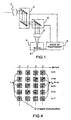
- FIG. 4 An example of temporal confirmation criterion is illustrated figure 4 considering 3 different cases, one case per line of the table.
- Each image I of this table results from an accumulation of Q images.
- the search area has a size equal to 3x3.
- the invention described so far performs the detection of targets that occupy only one pixel.
- a possible adaptation of the invention makes it possible to detect the targets of size greater than the pixel, by averaging by blocks of the image (called 'new pixels') to reduce the targets that one wants to detect to occupy only a new pixel.
Landscapes
- Engineering & Computer Science (AREA)
- Physics & Mathematics (AREA)
- General Physics & Mathematics (AREA)
- Theoretical Computer Science (AREA)
- Quality & Reliability (AREA)
- Remote Sensing (AREA)
- Radar, Positioning & Navigation (AREA)
- Computer Vision & Pattern Recognition (AREA)
- Electromagnetism (AREA)
- Multimedia (AREA)
- Image Analysis (AREA)
- Closed-Circuit Television Systems (AREA)
- Geophysics And Detection Of Objects (AREA)
- Television Signal Processing For Recording (AREA)
- Apparatus For Radiation Diagnosis (AREA)
Abstract
Description
Le domaine de l'invention est celui des systèmes optroniques de surveillance.The field of the invention is that of optronic monitoring systems.
Un système optronique de surveillance a pour fonction de détecter et suivre des cibles pénétrant dans une zone de surveillance.An optronic surveillance system has the function of detecting and tracking targets entering a surveillance zone.
Le problème crucial de la détection de cible (ou objet) dans une séquence vidéo est de trouver un critère désigné « critère de détection » qui permette de décider pour chaque image comportant des pixels, quels sont les pixels d'une cible. Le choix de ce critère conduit à des performances de détection définies en fonction du couple probabilité de détection - probabilité de fausse alarme.The crucial problem of target (or object) detection in a video sequence is to find a criterion designated "detection criterion" that makes it possible to decide for each image comprising pixels, which are the pixels of a target. The choice of this criterion leads to detection performances defined as a function of the couple probability of detection - probability of false alarm.
On rappelle que la probabilité de détection est la probabilité pour un pixel d'une cible (ou objet menaçant) d'être considéré comme probablement celui d'une cible ; la probabilité de fausse alarme est la probabilité pour un pixel d'un objet non menaçant d'être sélectionné comme étant probablement celui d'une cible.It is recalled that the probability of detection is the probability for a pixel of a target (or threatening object) to be considered as probably that of a target; the probability of false alarm is the probability for a pixel of a non-threatening object to be selected as probably that of a target.
Dans les systèmes de surveillance de cibles aériennes, on utilise généralement des images acquises dans les longueurs d'onde de l'infrarouge car elles offrent un bon critère de détection dans la mesure où la plupart des cibles sont propulsées et fournissent donc un signal IR élevé.In aerial target surveillance systems, images acquired in infrared wavelengths are generally used because they provide a good detection criterion since most targets are propelled and thus provide a high IR signal. .
Pour un système de surveillance air-air à longue portée, la détection consiste à discriminer avec une forte probabilité de détection et une faible probabilité de fausse alarme, un pixel pouvant présenter un faible rapport signal sur bruit (RSB), tel qu'un pixel dont le signal « cible» est faible comparé aux signaux des pixels d'arrière-plan.For a long-range air-to-air monitoring system, detection consists of discriminating with a high probability of detection and a low probability of false alarm, a pixel that may have a low signal-to-noise ratio (SNR), such as a pixel whose "target" signal is weak compared to the signals of the background pixels.
Les principales sources de fausses alarmes sont :
- des échantillons de bruit sur les pixels de l'arrière-plan de la cible qui produisent un signal additionnel comparable dans certains cas à celui d'une cible,
- des artefacts variant rapidement dans l'arrière-plan qui produisent un signal très important (reflets du soleil à la lisière des nuages par exemple).
- noise samples on the pixels of the background of the target which produce an additional signal comparable in some cases to that of a target,
- artifacts that vary rapidly in the background, producing a very important signal (for example, reflections from the sun at the edge of clouds).
Les systèmes considérés sont plus particulièrement les systèmes de surveillance à balayage basse fréquence fonctionnant avec un dispositif d'acquisition haute fréquence. Parmi ceux-ci on peut citer les systèmes décrits dans le document
La
Sur ces systèmes, le détecteur matriciel 41 couvre un bandeau de l'espace (de dimension « A x b ») par rotation des moyens de balayage 2. Dans ce cas, un point du secteur S n'est pas observé de façon permanente, mais avec une période plus ou moins courte selon le temps mis pour revenir sur ce point après avoir balayé l'ensemble du secteur S. Des moyens de contre-balayage 6 permettent : d'une part, d'assurer la stabilité de la ligne de visée pendant le temps d'intégration du détecteur matriciel 41 pour chaque image, d'autre part, d'observer la même zone « a x b » de l'espace (de dimension sensiblement égale au champ instantané du détecteur matriciel 41, ou éventuellement inférieure à celui-ci) tant que les moyens de balayage 2 du secteur ne nécessitent pas le passage à la zone suivante. En général, les moyens de balayage / contre-balayage 2, 6 assurent un certain recouvrement entre deux zones consécutives observées, pour éliminer le risque de formation de zones 'aveugles' dues à des erreurs dans les mécanismes, et pour traiter sans difficulté supplémentaire ie cas des cibles qui se déplacent dans le repère du détecteur matriciel.On these systems, the
Selon la fréquence d'acquisition des images et la vitesse de rotation des moyens de balayage, un certain nombre d'images de la même zone est donc obtenu (avec la même direction de visée).According to the acquisition frequency of the images and the rotation speed of the scanning means, a certain number of images of the same area are thus obtained (with the same direction of view).
Ces systèmes de surveillance sont caractérisés par :
- un délai important (pouvant atteindre plusieurs secondes) entre deux observations consécutives de la même zone lors de deux analyses successives du secteur S,
- un grand nombre N (de l'ordre de plusieurs dizaines) d'acquisitions d'images du même objet (ou cible) d'une scène à chaque balayage : N images consécutives incluent alors le même objet.
- a significant delay (up to several seconds) between two consecutive observations of the same zone during two successive sector S analyzes,
- a large number N (of the order of several tens) of acquisitions of images of the same object (or target) of a scene with each scan: N consecutive images then include the same object.
On a illustré ce procédé
Le secteur S d'un champ représenté par un angle A x B est balayé sur sa largeur A en T secondes, soit à une vitesse angulaire θ', par exemple 20° en 2 s, soit θ' = A/T = 10° s-1.The sector S of a field represented by an angle A x B is scanned over its width A at T seconds, ie at an angular velocity θ ', for example 20 ° in 2 s, or θ' = A / T = 10 ° s -1 .
Soit a la largeur angulaire du champ instantané du détecteur matriciel ; le temps consacré à l'acquisition des images d'une scène couvrant une largeur angulaire « a » est égal au temps nécessaire pour balayer cette largeur à la vitesse angulaire θ', soit t = a / θ', par exemple pour a = 1° et θ' = 10° s-1, t = 0.1 s.Let be the angular width of the instantaneous field of the matrix detector; the time devoted to acquiring the images of a scene covering an angular width "a" is equal to the time necessary to scan this width at the angular velocity θ ', ie t = a / θ', for example for a = 1 ° and θ '= 10 ° s -1 , t = 0.1 s.
Le terme largeur angulaire n'est pas limité à une orientation dans l'espace.The term angular width is not limited to an orientation in space.
Soit f la cadence d'échantillonnage du détecteur matriciel (cadence image), par exemple f = 400 Hz, soit une période d'échantillonnage te = 1/f = 2.5 ms.Let f be the sampling rate of the matrix detector (frame rate), for example f = 400 Hz, or a sampling period t e = 1 / f = 2.5 ms.
Alors le nombre N d'images consacrées à la même zone angulaire est égal à N = t / te = a f / θ', soit N = 40.Then the number N of images dedicated to the same angular zone is equal to N = t / t e = af / θ ', ie N = 40.
Sur la figure et pour ne pas la surcharger, un objet ponctuel O est donc présent dans 40 images consécutives, numérotées de n à n+39. Cet objet n'est pas présent dans les 40 images précédentes (numérotées de n-40 à n-1) ni dans les 40 images suivantes (numérotées de n+40 à n+79).In the figure and not to overload it, a point object O is therefore present in 40 consecutive images, numbered from n to n + 39. This object is not present in the previous 40 images (numbered from n-40 to n-1) nor in the following 40 images (numbered from n + 40 to n + 79).
Le problème est d'optimiser l'usage de ces N images pour détecter l'objet avec une forte probabilité de détection et éliminer le plus possible de fausses alarmes dues notamment à des artefacts.The problem is to optimize the use of these N images to detect the object with a high probability of detection and eliminate as much as possible false alarms due in particular to artifacts.
L'invention a pour objet un procédé de détection d'un objet dans une scène située dans un secteur angulaire S déterminé, et susceptible de comporter un ou plusieurs artéfacts (signaux de l'arrière-plan de forte amplitude et variant rapidement), qui comprend une étape de balayage du secteur dans sa largeur angulaire A à une vitesse angulaire θ', une étape d'acquisition d'images numériques consécutives de la scène à une fréquence f, ces images comportant des pixels et couvrant un champ 'instantané' de largeur angulaire « a ». Il est principalement caractérisé en ce qu'il comprend les étapes suivantes de traitement des images acquises, par lot de N images avec N = a f / θ' :
- répartir les N images en P groupes d'images, P étant un entier supérieur à 1,
- pour chaque groupe p, p compris
entre 1 et P, accumuler les images du groupe de manière à obtenir une image accumulée Ip incluant le pixel objet, - pour chaque image Ip, sélectionner les pixels qui vérifient un critère de détection déterminé,
- pour chaque image Ip comportant au moins un pixel sélectionné, dite image de départ de confirmation, effectuer une étape de confirmation temporelle qui comprend les sous-étapes suivantes :
- appliquer un critère de confirmation temporelle en comparant à un nombre prédéterminé K avec K<= P, le nombre k de fois que ce pixel sélectionné dans l'image de départ ou l'un de ses voisins a été sélectionné dans les images Ip suivantes, le pixel sélectionné dans l'image de départ étant compté dans k : ce pixel sera considéré comme celui d'un objet si k ≥ k,
- réitérer ce critère de confirmation temporelle pour tous les pixels sélectionnés de cette image de départ dans la mesure où ces pixels n'ont pas déjà été pris en compte dans un calcul de k.
- distribute the N images in P groups of images, P being an integer greater than 1,
- for each group p, p between 1 and P, accumulating the images of the group so as to obtain an accumulated image I p including the object pixel,
- for each image I p , select the pixels that satisfy a determined detection criterion,
- for each image I p having at least one selected pixel, said confirmation start image, performing a time confirmation step which comprises the following substeps:
- applying a temporal confirmation criterion by comparing with a predetermined number K with K <= P the number k of times that this pixel selected in the starting image or one of its neighbors has been selected in the following images I p , the pixel selected in the starting image being counted in k: this pixel will be considered as that of an object if k ≥ k,
- reiterate this temporal confirmation criterion for all the selected pixels of this starting image in the extent that these pixels have not already been taken into account in a calculation of k.
Ce procédé permet :
- de prendre en compte dans le critère de confirmation temporelle, le déplacement potentiel de l'objet dans des pixels voisins sélectionnés, ce déplacement étant dû au déplacement angulaire de la cible dans le repère du capteur et pendant le temps d'acquisition des N images,
- d'augmenter les performances d'élimination des artefacts car d'une part ceux-ci n'ont pas plus de poids que les cibles lors de l'application du critère de confirmation temporelle et que d'autre part les cibles ayant une corrélation temporelle supérieure à celle des artéfacts, l'application du critère élimine les artéfacts sans affaiblir la détection des cibles.
- to take into account in the criterion of temporal confirmation, the potential displacement of the object in selected neighboring pixels, this displacement being due to the angular displacement of the target in the reference of the sensor and during the acquisition time of N images,
- to increase the performances of elimination of the artefacts because on the one hand they have not more weight than the targets during the application of the temporal confirmation criterion and on the other hand the targets having a temporal correlation superior to that of artifacts, the application of the criterion eliminates artifacts without weakening the detection of targets.
Par le critère de confirmation temporelle, le procédé permet également de rejeter les cibles dont le déplacement angulaire est trop rapide, comme par exemple un objet qui ne constitue pas une menace et qui ne peut être détecté qu'à courte distance, tel un oiseau. En effet, le nombre d'images de chaque groupe est déterminé de manière à ce que le pixel objet ne présente pas de changement de pixel entre les images du groupe.By the temporal confirmation criterion, the method also makes it possible to reject targets whose angular displacement is too fast, such as an object that does not pose a threat and can only be detected at short range, such as a bird. Indeed, the number of images of each group is determined in such a way that the object pixel does not present a change of pixel between the images of the group.
Plus précisément selon une caractéristique de l'invention, le nombre d'images de chaque groupe p est déterminé en fonction de la vitesse angulaire supposée de la cible, de la taille θp de l'angle de visée du pixel et de la cadence image f et éventuellement en fonction de N.More precisely according to one characteristic of the invention, the number of images of each group p is determined as a function of the supposed angular velocity of the target, the size θ p of the angle of view of the pixel and the frame rate. f and possibly according to N.
K est typiquement déterminé en fonction de la durée supposée de présence des artéfacts et de la cadence image f.K is typically determined by the expected duration of artefact presence and frame rate f.
Selon une caractéristique de l'invention P est déterminé en fonction de N et du nombre d'images de chaque groupe.According to one characteristic of the invention P is determined as a function of N and the number of images of each group.
De préférence, un pixel est sélectionné lorsque RSB > seuil prédéterminé dans ce pixel.Preferably, a pixel is selected when RSB> predetermined threshold in this pixel.
Selon une autre caractéristique de l'invention, un pixel voisin est déterminé en fonction des déplacements admissibles de l'objet, d'une image Ip à l'autre, et/ou en fonction d'une trajectoire de pixels admissible.According to another characteristic of the invention, a neighboring pixel is determined according to the allowable displacements of the object, from one image I p to the other, and / or according to a permissible pixel trajectory.
Lorsque l'image d'un objet couvre plus d'un pixel, le procédé comprend avant l'étape de répartition des N images en P groupes, une étape de changement de l'échelle des pixels c'est-à-dire qu'un bloc de q x q anciens pixels devient un nouveau pixel, q étant un entier supérieur ou égal à 2, de manière à ce que l'image d'un objet ne couvre qu'un pixel.When the image of an object covers more than one pixel, the method comprises, before the step of distributing the N images in P groups, a step for changing the pixel scale, that is to say that a block of qxq old pixels becomes a new pixel, q being an integer greater than or equal to 2, so that the image of an object only covers one pixel.
La vitesse angulaire θ' n'est pas nécessairement constante. L'invention a aussi pour objet un système de surveillance d'un secteur S qui comporte :
- des moyens de balayage du secteur S dont la largeur angulaire A est balayée à une vitesse angulaire θ',
- des moyens de formation d'images de scènes situées dans ledit secteur S et susceptibles de comporter des artéfacts,
- des moyens de détection d'images numériques d'une scène, à une cadence f comprenant un détecteur matriciel présentant un ensemble de pixels,
- une unité de traitement des images détectées,
- sector scanning means S whose angular width A is scanned at an angular speed θ ',
- means for forming images of scenes located in said sector S and likely to include artifacts,
- means for detecting digital images of a scene, at a rate f comprising a matrix detector presenting a set of pixels,
- a unit for processing the detected images,
D'autres caractéristiques et avantages de l'invention apparaîtront à la lecture de la description détaillée qui suit, faite à titre d'exemple non limitatif et en référence aux dessins annexés dans lesquels :
- la
figure 1 déjà décrite représente schématiquement un système de surveillance selon l'état de la technique, - la
figure 2 déjà décrite illustre un procédé de surveillance à balayage basse fréquence avec une acquisition haute fréquence, selon l'état de la technique, - la
figure 3 illustre le problème posé par des artefacts, - la
figure 4 illustre des exemples de calcul de k, - la
figure 5 illustre différentes étapes d'un exemple de déroulement du procédé selon l'invention.
- the
figure 1 already described schematically represents a monitoring system according to the state of the art, - the
figure 2 already described illustrates a low frequency scanning monitoring method with high frequency acquisition, according to the state of the art, - the
figure 3 illustrates the problem posed by artifacts, - the
figure 4 illustrates examples of calculating k, - the
figure 5 illustrates different steps of an example of the procedure of the invention.
D'une figure à l'autre, les mêmes éléments sont repérés par les mêmes références.From one figure to another, the same elements are identified by the same references.
On va tout d'abord analyser plus en détail le problème posé par les artefacts.We will first analyze in more detail the problem posed by the artifacts.
Pour une image acquise, le signal s'exprime de la façon suivante selon qu'une cible est présente ou non dans le pixel correspondant et en cas de présence d'un artefact éphémère. ![]()
![]()
![]()
- où Scible est le signal de la cible,
- Sarrière-plan le signal de l'arrière-plan du pixel (appelé aussi le fond),
- Sbruit un échantillon aléatoire du bruit du capteur,
- Sartefact le signal de l'artefact qui n'apparaît que dans quelques images consécutives,
- Squick-dutter le signal bruité de l'artefact.
- where S target is the signal of the target,
- S background the signal from the background of the pixel (also called the background),
- S noise a random sample of the sensor noise,
- S artefact the artifact signal that only appears in a few consecutive frames,
- S quick-dutter the noisy signal of the artifact.
On a : Sartefact >> Scible et Sartefact >> Sbruit We have: S artifact >> S target and S artifact >> S noise
Un pistage ultérieur est basé sur une association temporelle des cibles détectées à chaque balayage du secteur. En raison du délai, qui peut être important, entre deux observations consécutives de la même zone lors de deux analyses successives du secteur S, un objet mobile présente d'une image (en fait d'un groupe d'images accumulées) à l'autre un déplacement angulaire qui peut être important et qui nécessite donc une large zone de recherche pour réaliser l'association temporelle, ce qui augmente les risques d'association ambiguë.A subsequent tracking is based on a temporal association of the targets detected with each scan of the sector. Because of the delay, which can be significant, between two consecutive observations of the same area during two successive analyzes of the sector S, a moving object presents an image (in fact of a group of accumulated images) to the other angular displacement which can be important and which therefore requires a large area of research to achieve the temporal association, which increases the risks of ambiguous association.
Le problème est donc d'optimiser l'usage des N images proches temporellement pour détecter la cible avec une forte probabilité de détection et éliminer le plus possible de fausses alarmes, afin de réduire la probabilité de mauvaises associations en vue d'un pistage ultérieur.The problem is therefore to optimize the use of N near-temporal images to detect the target with a high probability of detection and to eliminate as much as possible false alarms, in order to reduce the probability of bad associations for subsequent tracking.
On rappelle que N=af/θ'. Selon l'invention, la vitesse angulaire θ' n'est pas nécessairement constante.We recall that N = af / θ '. According to the invention, the angular velocity θ 'is not necessarily constant.
L'accumulation des N images permettrait d'augmenter le S/B. Pour une cible fixe, l'intensité moyenne d'un pixel issu de cette accumulation suivie d'une division par N est donnée par les équations : ![]()
![]()
![]()

![]()
![]()
![]()
Cette solution optimise l'élimination des fausses alarmes dues au bruit. Mais dans le cas d'une cible mobile qui peut changer de pixels pendant l'acquisition des N images, le signal résultant peut devenir dilué entre des pixels adjacents. Le bruit est réduit mais celui de la cible l'est aussi alors que le signal de l'arrière-plan ne change pas. Par exemple, pour une cible qui change de pixel à chaque image, on a : 
On va détailler ceci sur un exemple illustré
- la cible fixe (1ère colonne) : 3 S1/3 = S1,
- l'artefact (2è colonne) : S2/3,
- la cible à mouvement lent (3è colonne) : S3/3, S3/3, S3/3.
- the fixed target (1 st column): 3 S 1/3 = S 1,
- artifact (2nd column): S 2/3,
- the slow moving target (3rd column): S 3/3, S 3/3, S 3/3.
En outre, les hauts artefacts qui arrivent ponctuellement dans une seule image peuvent aboutir à un signal accumulé supérieur à celui d'une cible peu mobile. En d'autres termes, 
Une solution connue pour résoudre ce problème de cible mobile consiste à appliquer la méthode « poursuite avant détection » ou « track before detect method » en anglais. Pour chaque pixel, sont faites M hypothèses de trajectoires. Pour chacune de ces hypothèses, les positions de la cible déduites au cours du temps sont accumulées. L'hypothèse retenue est l'hypothèse de trajectoire qui maximise le signal accumulé.A known solution to solve this mobile target problem is to apply the method "track before detect" or "track before detect method" in English. For each pixel, are made M hypotheses of trajectories. For each of these assumptions, the positions of the target deducted over time are accumulated. The hypothesis adopted is the trajectory hypothesis that maximizes the accumulated signal.
Cette solution traite efficacement le problème d'une cible se déplaçant: on obtient le même signal accumulé que celui que l'on obtiendrait pour une cible fixe. Mais chaque hypothèse de trajectoire peut mener à une fausse alarme sur des pixels d'arrière-plan par accumulation d'échantillons de bruit : la probabilité résultante de fausse d'alarme est alors supérieure à la probabilité de fausse d'alarme que l'on aurait obtenue par le procédé classique d'accumulation d'images. De plus, comme indiqué plus haut, les hauts artefacts qui arrivent ponctuellement dans une seule image peuvent aboutir à un signal accumulé supérieur à celui d'une cible peu mobile. En d'autres termes, 
Le procédé selon l'invention décrit en relation avec les
Le nombre Q d'images par groupe est déterminé de manière à ce que la cible ne présente pas de changement de pixel entre les Q images. Les P groupes d'images sont ensuite utilisés de la façon suivante :
- pour chaque groupe, accumuler les Q images de manière à obtenir une image accumulée I1, ..., Ip, ..., Ip,
- pour chaque image Ip, sélectionner les pixels qui vérifient un critère de détection déterminé; ce critère peut être tel qu'un pixel est sélectionné lorsque le RSB dans ce pixel est supérieur à un seuil prédéterminé (il s'agit du RSB auquel on a accès, qui est en général un RSB estimé), ou tel que le signal du pixel est supérieur à un autre seuil prédéterminé,
- pour chaque image Ip comportant au moins un pixel sélectionné, dite image de départ de confirmation, effectuer une étape de confirmation temporelle qui comprend les sous-étapes suivantes :
- appliquer un critère de confirmation temporelle en comparant à un nombre prédéterminé K (on a K<= P), le nombre k de fois que ce pixel sélectionné dans l'image de départ ou l'un de ses voisins a été sélectionné dans les images Ip suivantes, le pixel sélectionné dans l'image de départ étant compté dans k : ce pixel sera considéré comme celui d'un objet si k ≥ K,
- réitérer ce critère de confirmation temporelle pour tous les pixels sélectionnés de cette image de départ dans la mesure où ces pixels n'ont pas déjà été pris en compte dans un calcul de k.
- for each group, accumulate the Q images so as to obtain an accumulated image I 1 , ..., I p , ..., I p ,
- for each image I p , select the pixels that satisfy a determined detection criterion; this criterion may be such that a pixel is selected when the SNR in that pixel is greater than a predetermined threshold (this is the SNR that is accessed, which is usually an estimated SNR), or such that the pixel is greater than another predetermined threshold,
- for each image I p having at least one selected pixel, said confirmation start image, performing a time confirmation step which comprises the following substeps:
- applying a temporal confirmation criterion by comparing to a predetermined number K (we have K <= P), the number k of times that this pixel selected in the initial image or one of its neighbors has been selected in the following images I p , the pixel selected in the initial image being counted in k: this pixel will be considered as that of an object if k ≥ K,
- reiterate this temporal confirmation criterion for all the selected pixels of this starting image insofar as these pixels have not already been taken into account in a calculation of k.
Comme indiqué plus haut, Q est déterminé de manière à ce que la cible ne présente pas de changement de pixel entre les Q images.As indicated above, Q is determined so that the target does not exhibit a pixel change between the Q images.
Les variables Q et K sont déterminées de la façon suivante.The variables Q and K are determined as follows.
Q est déterminé de manière à ce que le pixel objet ne présente pas de changement de pixel entre les Q images. Plus précisément, Q est déterminé en fonction de la vitesse angulaire supposée de la cible, de la taille du pixel en angle et de la cadence image. Si le détecteur matriciel comprend C colonnes et L lignes, la taille θp de l'angle de visée du pixel est égale à : ![]()
![]()
Précisément, soit ω'c la vitesse de défilement angulaire de la cible, θp la taille angulaire d'un pixel et te la période image, alors on doit avoir : ![]()
![]()
Pour donner des ordres de grandeur, si la cible est à une distance de 100 kilomètres et se déplace à 300 ms-1 perpendiculairement à la ligne capteur-cible, la vitesse de déplacement angulaire est ω'c = 3.10-3 rad s-1 ; si le pixel a une taille angulaire θp = 35 µrad et si te = 2.5 ms (cadence image de 400 Hz), alors on trouve Q ≤4,67, on pourra donc prendre Q = 4.To give orders of magnitude, if the target is at a distance of 100 kilometers and moves at 300 ms -1 perpendicular to the sensor-target line, the angular displacement speed is ω ' c = 3.10 -3 rad s -1 ; if the pixel has an angular size θ p = 35 μrad and if t e = 2.5 ms (image rate of 400 Hz), then we find Q ≤4.67, so we can take Q = 4.
On en déduit P = N/Q. Si N/Q n'est pas entier, on prendra P = E(N/Q) + 1 où E désigne la partie entière, en acceptant que la dernière image accumulée résulte d'une accumulation sur un nombre d'images plus petit que Q, ce qui peut être pris en compte dans la détermination du seuil de détection. Par exemple, si N = 40 et Q = 6, on prendra P = 7, et on disposera de 6 images Ip résultats d'une accumulation sur Q = 6 images élémentaires et d'une image Ip résultat d'une accumulation sur Q=4 images élémentaires.We deduce P = N / Q. If N / Q is not integer, we take P = E (N / Q) + 1 where E denotes the integer part, accepting that the last accumulated image results from an accumulation on a smaller number of images than Q, which can be taken into account in the determination of the detection threshold. For example, if N = 40 and Q = 6, we will take P = 7, and we will have 6 images I p results of an accumulation on Q = 6 elementary images and an image I p result of an accumulation on Q = 4 elementary images.
K est déterminé en fonction de la durée supposée de présence des artéfacts et de la cadence image multipliée par Q. Par exemple, pour Q = 4 et te = 2,5 ms, la durée de chaque groupe d'images est de 10 ms (c'est le temps nécessaire pour obtenir une image accumulée), et donc P = 10. Si la durée maximale considérée pour la présence d'un artefact est inférieure à 10 ms, on prendra K = 2, en effet dans ce cas k ne pourra excéder 1 pour un artefact. Si la durée maximale est inférieure à 20 ms, on prendra K = 3 etc.K is determined by the expected duration of artifact presence and the frame rate multiplied by Q. For example, for Q = 4 and t e = 2.5 ms, the duration of each group of images is 10 ms (it's the time required to obtain an accumulated image), and therefore P = 10. If the maximum duration considered for the presence of an artifact is less than 10 ms, we will take K = 2, in fact in this case k can not exceed 1 for an artifact. If the maximum duration is less than 20 ms, we will take K = 3 etc.
L'ensemble des pixels voisins déterminé au cours d'une phase dite d'association, est par exemple défini en prenant en compte le déplacement admissible de la cible dans les P groupes d'images. Il s'agit de déterminer à partir du pixel sélectionné dans le premier groupe d'images Ip où l'étape de confirmation temporelle est réalisée, quels sont les pixels 'candidats au voisinage' pour les groupes d'images Ip suivants.The set of neighboring pixels determined during a so-called association phase, for example, is defined by taking into account the permissible displacement of the target in the P groups of images. It is a question of determining from the pixel selected in the first group of images I p where the temporal confirmation step is carried out, which pixels are 'neighborhood candidates' for the following groups of images I p .
Par exemple, en se basant sur les mêmes ordres de grandeur que ceux qui ont été définis précédemment (distance capteur-cible = 100 km, vitesse de la cible = 300 ms-1 perpendiculairement à la ligne capteur-cible, taille angulaire du pixel θp = 35 µrad, te = 2.5 ms), on a vu que la cible était susceptible de se déplacer de 1 pixel pour chaque groupe d'images Ip, en fait légèrement moins car Q a été pris égal à 4 (qui est la partie entière de 4,67).For example, based on the same orders of magnitude as those previously defined (sensor-target distance = 100 km, target speed = 300 ms -1 perpendicular to the sensor-target line, angular size of the pixel θ p = 35 μrad, t e = 2.5 ms), we saw that the target was likely to move by 1 pixel for each group of images I p , actually slightly less because Q was taken equal to 4 (which is the whole part of 4.67).
Dans ces conditions, on procède de la façon itérative suivante : on retient, autour du pixel sélectionné dans le premier groupe d'images Ip, une zone carrée Z de 3x3 pixels, puisque l'on sait que la cible peut se déplacer de un pixel à chaque groupe d'images et qu'on ne connaît pas a priori sa direction angulaire. Si dans le groupe d'images suivant, un pixel de Z a été sélectionné par le processus de détection, ce pixel sera retenu pour la suite ; dans le cas contraire, la zone Z pourra être agrandie (taille 5x5) pour le groupe d'images suivant et ainsi de suite jusqu'à la fin des P groupes d'images. A chaque fois qu'un pixel sélectionné est retenu, il est pris comme nouveau centre des zones à définir ultérieurement.Under these conditions, we proceed in the following iterative way: we retain, around the pixel selected in the first group of images Ip, a square zone Z of 3x3 pixels, since we know that the target can move a pixel to each group of images and that we do not know a priori its angular direction. If in the next group of images, a pixel of Z has been selected by the detection process, this pixel will be retained for the rest; in the opposite case, the zone Z can be enlarged (size 5x5) for the next group of images and so on until the end of the P groups of images. Each time a selected pixel is selected, it is taken as the new center of the zones to be defined later.
La méthode décrite pour définir l'ensemble des pixels voisins est un exemple de réalisation. D'autres modes de réalisation sont possibles, soit plus simples (sélection a priori d'une zone Z suffisamment grande autour du pixel sélectionné dans le premier groupe d'images, zone valable pour la totalité des P groupes d'images), soit plus sophistiqués, permettant de traiter les cas où deux cibles viennent interférer dans les mêmes voisinages.The method described for defining all the neighboring pixels is an exemplary embodiment. Other embodiments are possible, either simpler (a priori selection of a zone Z sufficiently large around the pixel selected in the first group of images, zone valid for all the P groups of images), or more sophisticated, to deal with cases where two targets interfere in the same neighborhoods.
Le critère de confirmation temporelle peut être complété par une étape complémentaire qui consiste à décider si l'ensemble des pixels voisins ainsi définis correspond bien à un objet dont le déplacement dans les P groupes d'images est conforme à ce que l'on attend d'une cible.The temporal confirmation criterion can be completed by a complementary step which consists in deciding whether the set of neighboring pixels thus defined corresponds to an object whose displacement in P groups of images is consistent with what is expected of a target.
Pour cette étape complémentaire, on applique par exemple un critère de 'trajectoire' à l'ensemble des pixels retenus au cours de la phase d'association. En effet, celle-ci peut conduire à une trajectoire aberrante du type changement brutal de la direction du déplacement angulaire de la cible, correspondant à une accélération qui ne peut pas être celle d'une cible. Le critère applicable est par exemple que la trajectoire des pixels retenus soit suffisamment proche d'une droite.For this complementary step, for example, a 'path' criterion is applied to all the pixels retained during the association phase. Indeed, it can lead to an aberrant trajectory of the sudden change in direction of angular displacement of the target, corresponding to an acceleration that can not be that of a target. The applicable criterion is for example that the trajectory of the pixels retained is sufficiently close to a line.
Ce procédé permet :
- de prendre en compte dans le critère de confirmation temporelle, le déplacement potentiel de la cible dans des pixels voisins sélectionnés,
- d'augmenter les performances d'élimination des artefacts car d'une part ceux-ci n'ont pas plus de poids que les cibles lors de l'application du critère de confirmation temporelle et d'autre part les cibles ayant une corrélation temporelle supérieure à celle des artéfacts, l'application du critère élimine les artéfacts sans affaiblir la détection des cibles.
- to take into account in the criterion of temporal confirmation, the potential displacement of the target in selected neighboring pixels,
- to increase the elimination performance of the artefacts because on the one hand they have no more weight than the targets when applying the temporal confirmation criterion and on the other hand the targets having a higher temporal correlation to that of artifacts, the application of the criterion eliminates artifacts without weakening the detection of targets.
Par le critère de confirmation temporelle, le procédé permet également de rejeter les cibles dont le déplacement angulaire est trop rapide. En effet, Q est déterminé de manière à ce que la cible ne présente pas de changement de pixel entre les Q images, comme indiqué précédemment.By the temporal confirmation criterion, the method also makes it possible to reject targets whose angular displacement is too fast. Indeed, Q is determined so that the target does not have a pixel change between the Q images, as indicated above.
Un exemple de critère de confirmation temporelle est illustré
Le nombre k de fois qu'un pixel ou l'un de ses voisins est extrait des P groupes d'images est :
- k=4 pour la cible fixe (1ère ligne),
- k=4 pour la cible à déplacement lent (2è ligne),
- k=2 pour la cible à déplacement rapide (3è ligne),
- k=3 pour la cible à déplacement erratique (4è ligne),
- k=1 pour l'artefact (5è ligne).
- k = 4 to the fixed target (1st line),
- k = 4 for the slow moving target (2nd line),
- k = 2 for the fast-moving target (3rd line),
- k = 3 for the erratic displacement target (4th line),
- k = 1 for the artifact (5th line).
Le critère de confirmation temporelle consiste à déterminer une valeur pour K, ici K=3 et à éliminer les images pour lesquelles k<K, en l'occurrence le cas de la cible trop mobile pour laquelle k=2 ainsi que celui de l'artefact pour lequel k=1.The criterion of temporal confirmation consists in determining a value for K, here K = 3 and eliminating the images for which k <K, in this case the case of the too mobile target for which k = 2 and that of the artifact for which k = 1.
Les différentes étapes du procédé de détection sont représentées
L'invention décrite jusqu'à présent effectue la détection de cibles qui n'occupent qu'un pixel. Une adaptation possible de l'invention permet de détecter les cibles de taille supérieure au pixel, par moyennage par blocs de l'image (dits 'nouveaux pixels') jusqu'à ramener les cibles que l'on veut détecter à n'occuper qu'un nouveau pixel.The invention described so far performs the detection of targets that occupy only one pixel. A possible adaptation of the invention makes it possible to detect the targets of size greater than the pixel, by averaging by blocks of the image (called 'new pixels') to reduce the targets that one wants to detect to occupy only a new pixel.
Si par exemple l'on connaît seulement la taille maximale des cibles à détecter, on peut ainsi analyser consécutivement des images moyennées par blocs 2 x 2, 3 x 3,... jusqu'à p x p, ce qui revient à « dézoomer » l'image, c'est-à-dire à changer l'échelle du repère O,x,y de l'image : un bloc de q x q anciens pixels devient un nouveau pixel, q étant un entier supérieur ou égal à 2 et pouvant aller jusqu'au nombre p qui correspond à la taille maximale des cibles à détecter. Cette étape intervient avant de répartir les images en Q groupes d'images.If for example we only know the maximum size of the targets to be detected, we can analyze consecutively images averaged by blocks 2 x 2, 3 x 3, ... up to pxp, which amounts to "dezoom" l image, that is to say to change the scale of the frame O, x, y of the image: a block of qxq old pixels becomes a new pixel, q being an integer greater than or equal to 2 and able to go up to the number p which corresponds to the maximum size of the targets to be detected. This step occurs before dividing the images into Q groups of images.
Le procédé décrit est typiquement mis en oeuvre dans un système de surveillance d'un secteur S qui comporte :
- des moyens de balayage 2 du secteur S dont la largeur angulaire A est balayée à une vitesse angulaire θ',
- des moyens 3 de formation d'images de scènes situées dans ledit secteur S et susceptibles de comporter des artéfacts,
- des moyens 4 de détection d'images numériques d'une scène, à une cadence f comprenant un détecteur matriciel 41 présentant un ensemble de pixels,
une unité 5 de traitement des images détectées qui comprend des moyens de mise en oeuvre du procédé décrit.
- scanning means 2 of the sector S whose angular width A is scanned at an angular speed θ ',
- means 3 for forming images of scenes located in said sector S and likely to include artifacts,
- means 4 for detecting digital images of a scene, at a rate f comprising a
matrix detector 41 presenting a set of pixels, - a
unit 5 for processing the detected images which comprises means for implementing the method described.
Ces moyens de mise en oeuvre sont classiquement des moyens logiciels.These means of implementation are conventionally software means.
Claims (12)
- A method for detecting an object in a scene that is situated in a determined angular sector S and that is susceptible to comprise one or more artefacts, which method comprises a step of scanning the sector along its angular width A at an angular speed θ', a step of acquiring consecutive digital images of the scene at a frequency f, said images comprising pixels and covering an 'instantaneous' field of angular width "a", comprising the following steps of processing the acquired images per batch of N images:- accumulating images so as to obtain an accumulated image,- selecting, for each accumulated image, the pixels that verify a determined detection criterion,characterised in that N = a f / θ' and in that prior to the accumulation step it comprises the following step:distributing the N images into P groups of images, P being an integer that is greater than 1, and in that the accumulation is applied for each group p, p being between 1 and P, the accumulated image being designated Ip, and in that after the accumulation step it comprises the following step:- performing a time confirmation step for each image Ip that comprises at least one selected pixel, referred to as the confirmation start image, which step comprises the following sub-steps:- applying a time confirmation criterion by comparing with a predetermined number K, where K<=P, the number k of times that this pixel that is selected in the start image, or one in the vicinity thereof, has been selected in the following images Ip, the pixel selected in the start image being counted in k, which pixel will be considered to be that of an object if k ≥K,- reiterating this time confirmation criterion for all of the selected pixels of this start image in so far as these pixels have not already been included in a calculation of k.
- The method according to the preceding claim, characterised in that the number of images of each group p is determined as a function of the presumed angular speed of the object, of the size of the viewing angle of the pixel and of the image rate f of the detector.
- The method according to the preceding claim, characterised in that the number of images of each group p is further determined as a function ofN.
- The method according to any one of the preceding claims, characterised in that P is determined as a function ofN and of the number of images of each group.
- The method according to any one of the preceding claims, characterised in that K is determined as a function of the presumed duration of the presence of the artefacts and of the image rate f.
- The method according to any one of the preceding claims, characterised in that a pixel is selected when RSB is greater than a predetermined threshold.
- The method according to any one of claims 1 to 5, characterised in that a pixel is selected when the signal of the pixel is greater than a predetermined threshold.
- The method according to any one of the preceding claims, characterised in that an adjacent pixel is determined as a function of the admissible movements of the object, from one image Ip to the other.
- The method according to any one of the preceding claims, characterised in that an adjacent pixel is determined as function of a trajectory of admissible pixels.
- The method according to any one of the preceding claims, characterised in that when the image of an object covers more than one pixel, and before the step of distributing the N images into P groups, it comprises a step of changing the scale of the pixels, that is that a block of q x q old pixels becomes a new pixel, q being an integer that is greater than or equal to 2, so that the image of an object covers only one pixel.
- The method according to any one of the preceding claims, characterised in that the angular speed θ' is constant.
- A system for monitoring a sector S that comprises:- means (2) for scanning the sector S, the angular length A of which is scanned at an angular speed θ',- means (3) for forming images of scenes that are situated in said sector S and that are susceptible to comprise artefacts,- means (4) for detecting digital images of the scene, at a rate f comprising a matrix detector (41) having a set of pixels,- a unit (5) for processing the detected images,characterised in that the processing unit (5) comprises means for implementing the method according to the preceding claims.
Applications Claiming Priority (2)
| Application Number | Priority Date | Filing Date | Title |
|---|---|---|---|
| FR0803167A FR2932278B1 (en) | 2008-06-06 | 2008-06-06 | METHOD FOR DETECTING AN OBJECT IN A SCENE COMPRISING ARTIFACTS |
| PCT/EP2009/056908 WO2010003742A1 (en) | 2008-06-06 | 2009-06-05 | Method of detecting an object in a scene comprising artefacts |
Publications (2)
| Publication Number | Publication Date |
|---|---|
| EP2294441A1 EP2294441A1 (en) | 2011-03-16 |
| EP2294441B1 true EP2294441B1 (en) | 2012-02-22 |
Family
ID=40377160
Family Applications (1)
| Application Number | Title | Priority Date | Filing Date |
|---|---|---|---|
| EP09793898A Active EP2294441B1 (en) | 2008-06-06 | 2009-06-05 | Method of detecting an object in a scene comprising artefacts |
Country Status (7)
| Country | Link |
|---|---|
| US (1) | US8558891B2 (en) |
| EP (1) | EP2294441B1 (en) |
| AT (1) | ATE546742T1 (en) |
| ES (1) | ES2381987T3 (en) |
| FR (1) | FR2932278B1 (en) |
| IL (1) | IL209788A (en) |
| WO (1) | WO2010003742A1 (en) |
Families Citing this family (6)
| Publication number | Priority date | Publication date | Assignee | Title |
|---|---|---|---|---|
| CN102025626B (en) * | 2010-12-09 | 2014-12-10 | 中兴通讯股份有限公司 | Method for forwarding multicast data message and provider edge |
| RU2480780C1 (en) * | 2011-10-28 | 2013-04-27 | Государственное образовательное учреждение высшего профессионального образования "Военная академия войсковой противовоздушной обороны Вооруженных Сил Российской Федерации" Министерства обороны Российской Федерации | Method of detecting point thermal objects on masking atmospheric background |
| FR3112229B1 (en) * | 2020-07-02 | 2022-07-15 | Thales Sa | METHOD FOR ACQUIRING IMAGES OF A SCENE |
| RU2755075C1 (en) * | 2020-11-23 | 2021-09-14 | Федеральное государственное унитарное предприятие "Всероссийский научно-исследовательский институт метрологии им. Д.И. Менделеева" | Method for over-horizontal detection of man-general marine objects |
| TR202019736A2 (en) * | 2020-12-04 | 2022-06-21 | Aselsan Elektronik Sanayi Ve Ticaret As | NOISE ANTI-NOISE METHOD FOR DETECTION APPLICATIONS |
| CN114271791B (en) * | 2022-01-12 | 2023-03-24 | 广州永士达医疗科技有限责任公司 | Artifact detection method and device of OCT imaging system |
Family Cites Families (7)
| Publication number | Priority date | Publication date | Assignee | Title |
|---|---|---|---|---|
| US4931868A (en) * | 1988-05-31 | 1990-06-05 | Grumman Aerospace Corporation | Method and apparatus for detecting innovations in a scene |
| US5210798A (en) * | 1990-07-19 | 1993-05-11 | Litton Systems, Inc. | Vector neural network for low signal-to-noise ratio detection of a target |
| US5379044A (en) * | 1993-12-23 | 1995-01-03 | Hughes Aircraft Company | Efficient multi-target tracking method |
| GB9720852D0 (en) * | 1997-10-02 | 1998-02-11 | Barr & Stroud Ltd | Method and apparatus for target track identification |
| FR2830339B1 (en) * | 2001-10-02 | 2003-12-12 | Thales Sa | PASSIVE WATCH OPTRONIC DEVICE |
| AU2003207979A1 (en) * | 2002-02-06 | 2003-09-02 | Nice Systems Ltd. | Method and apparatus for video frame sequence-based object tracking |
| FR2875626B1 (en) * | 2004-09-21 | 2006-11-17 | Thales Sa | METHOD FOR DETECTING AND PITCHING TARGET TARGETS IN AN OPTRONIC MONITORING SYSTEM |
-
2008
- 2008-06-06 FR FR0803167A patent/FR2932278B1/en not_active Expired - Fee Related
-
2009
- 2009-06-05 US US12/996,597 patent/US8558891B2/en active Active
- 2009-06-05 ES ES09793898T patent/ES2381987T3/en active Active
- 2009-06-05 WO PCT/EP2009/056908 patent/WO2010003742A1/en active Application Filing
- 2009-06-05 AT AT09793898T patent/ATE546742T1/en active
- 2009-06-05 EP EP09793898A patent/EP2294441B1/en active Active
-
2010
- 2010-12-06 IL IL209788A patent/IL209788A/en active IP Right Grant
Also Published As
| Publication number | Publication date |
|---|---|
| US8558891B2 (en) | 2013-10-15 |
| EP2294441A1 (en) | 2011-03-16 |
| ATE546742T1 (en) | 2012-03-15 |
| FR2932278A1 (en) | 2009-12-11 |
| WO2010003742A1 (en) | 2010-01-14 |
| ES2381987T3 (en) | 2012-06-04 |
| IL209788A0 (en) | 2011-02-28 |
| IL209788A (en) | 2015-03-31 |
| US20110080480A1 (en) | 2011-04-07 |
| FR2932278B1 (en) | 2010-06-11 |
Similar Documents
| Publication | Publication Date | Title |
|---|---|---|
| EP2294441B1 (en) | Method of detecting an object in a scene comprising artefacts | |
| EP3138079B1 (en) | Method of tracking shape in a scene observed by an asynchronous light sensor | |
| EP3103102B1 (en) | Method for detecting and tracking targets | |
| EP3572976A1 (en) | Method for processing a video image stream | |
| FR2674340A1 (en) | METHOD FOR DETECTING AND CLASSIFYING FEATURES IN SONAR IMAGES. | |
| EP3049822B1 (en) | Method for non-supervised deinterleaving by n-dimensional enrichment | |
| EP2239597A1 (en) | Airborne radar for multimode ground surveillance | |
| EP3200153A1 (en) | Method for detecting targets on the ground and in motion, in a video stream acquired with an airborne camera | |
| EP1792278B1 (en) | Method for detecting and tracking punctual targets, in an optoelectronic surveillance system | |
| WO2020260649A1 (en) | Radar device for detecting reference behaviour of tracked targets; associated method and computer program product | |
| FR2916562A1 (en) | METHOD FOR DETECTING A MOVING OBJECT IN AN IMAGE STREAM | |
| EP3959648B1 (en) | Method for detecting targets | |
| EP2544020A1 (en) | Method and device for detecting a target masked by high-energy reflectors | |
| EP3216213B1 (en) | Method for detecting defective pixels | |
| EP3324361B1 (en) | Method for detecting and tracking targets | |
| EP3718082B1 (en) | Method for detecting and tracking targets | |
| EP3709049B1 (en) | Radar processing system and related noise reduction method | |
| FR3050829A1 (en) | METHOD OF OPTIMIZING THE DETECTION OF MARINE TARGETS AND AIRBORNE RADAR USING SUCH A METHOD | |
| EP4176582B1 (en) | Method for acquiring images of a scene | |
| EP2715668A1 (en) | Detection and tracking of targets in a series of images | |
| EP3397984B1 (en) | Telemetry method and system using an imager | |
| FR3038760A1 (en) | DETECTION OF OBJECTS BY PROCESSING IMAGES | |
| EP3506578B1 (en) | Radio-frequency transmitter detection method and associated device | |
| EP4025503B1 (en) | System and method for analysing single satellite orbits | |
| FR3127295A1 (en) | METHOD FOR AUTOMATIC IDENTIFICATION OF TARGET(S) WITHIN IMAGE(S) PROVIDED BY A SYNTHETIC APERTURE RADAR |
Legal Events
| Date | Code | Title | Description |
|---|---|---|---|
| PUAI | Public reference made under article 153(3) epc to a published international application that has entered the european phase |
Free format text: ORIGINAL CODE: 0009012 |
|
| 17P | Request for examination filed |
Effective date: 20101206 |
|
| AK | Designated contracting states |
Kind code of ref document: A1 Designated state(s): AT BE BG CH CY CZ DE DK EE ES FI FR GB GR HR HU IE IS IT LI LT LU LV MC MK MT NL NO PL PT RO SE SI SK TR |
|
| AX | Request for extension of the european patent |
Extension state: AL BA RS |
|
| RIN1 | Information on inventor provided before grant (corrected) |
Inventor name: LEMPERIERE, NADEGE Inventor name: PRENAT, MICHEL Inventor name: DUFOUR, JEAN-YVES |
|
| GRAP | Despatch of communication of intention to grant a patent |
Free format text: ORIGINAL CODE: EPIDOSNIGR1 |
|
| DAX | Request for extension of the european patent (deleted) | ||
| GRAS | Grant fee paid |
Free format text: ORIGINAL CODE: EPIDOSNIGR3 |
|
| GRAA | (expected) grant |
Free format text: ORIGINAL CODE: 0009210 |
|
| AK | Designated contracting states |
Kind code of ref document: B1 Designated state(s): AT BE BG CH CY CZ DE DK EE ES FI FR GB GR HR HU IE IS IT LI LT LU LV MC MK MT NL NO PL PT RO SE SI SK TR |
|
| REG | Reference to a national code |
Ref country code: GB Ref legal event code: FG4D Free format text: NOT ENGLISH |
|
| REG | Reference to a national code |
Ref country code: CH Ref legal event code: EP |
|
| REG | Reference to a national code |
Ref country code: AT Ref legal event code: REF Ref document number: 546742 Country of ref document: AT Kind code of ref document: T Effective date: 20120315 |
|
| REG | Reference to a national code |
Ref country code: IE Ref legal event code: FG4D Free format text: LANGUAGE OF EP DOCUMENT: FRENCH |
|
| REG | Reference to a national code |
Ref country code: DE Ref legal event code: R096 Ref document number: 602009005541 Country of ref document: DE Effective date: 20120419 |
|
| REG | Reference to a national code |
Ref country code: ES Ref legal event code: FG2A Ref document number: 2381987 Country of ref document: ES Kind code of ref document: T3 Effective date: 20120604 |
|
| REG | Reference to a national code |
Ref country code: NL Ref legal event code: VDEP Effective date: 20120222 |
|
| LTIE | Lt: invalidation of european patent or patent extension |
Effective date: 20120222 |
|
| PG25 | Lapsed in a contracting state [announced via postgrant information from national office to epo] |
Ref country code: IS Free format text: LAPSE BECAUSE OF FAILURE TO SUBMIT A TRANSLATION OF THE DESCRIPTION OR TO PAY THE FEE WITHIN THE PRESCRIBED TIME-LIMIT Effective date: 20120622 Ref country code: NL Free format text: LAPSE BECAUSE OF FAILURE TO SUBMIT A TRANSLATION OF THE DESCRIPTION OR TO PAY THE FEE WITHIN THE PRESCRIBED TIME-LIMIT Effective date: 20120222 Ref country code: LT Free format text: LAPSE BECAUSE OF FAILURE TO SUBMIT A TRANSLATION OF THE DESCRIPTION OR TO PAY THE FEE WITHIN THE PRESCRIBED TIME-LIMIT Effective date: 20120222 Ref country code: NO Free format text: LAPSE BECAUSE OF FAILURE TO SUBMIT A TRANSLATION OF THE DESCRIPTION OR TO PAY THE FEE WITHIN THE PRESCRIBED TIME-LIMIT Effective date: 20120522 Ref country code: HR Free format text: LAPSE BECAUSE OF FAILURE TO SUBMIT A TRANSLATION OF THE DESCRIPTION OR TO PAY THE FEE WITHIN THE PRESCRIBED TIME-LIMIT Effective date: 20120222 |
|
| PG25 | Lapsed in a contracting state [announced via postgrant information from national office to epo] |
Ref country code: GR Free format text: LAPSE BECAUSE OF FAILURE TO SUBMIT A TRANSLATION OF THE DESCRIPTION OR TO PAY THE FEE WITHIN THE PRESCRIBED TIME-LIMIT Effective date: 20120523 Ref country code: LV Free format text: LAPSE BECAUSE OF FAILURE TO SUBMIT A TRANSLATION OF THE DESCRIPTION OR TO PAY THE FEE WITHIN THE PRESCRIBED TIME-LIMIT Effective date: 20120222 Ref country code: PT Free format text: LAPSE BECAUSE OF FAILURE TO SUBMIT A TRANSLATION OF THE DESCRIPTION OR TO PAY THE FEE WITHIN THE PRESCRIBED TIME-LIMIT Effective date: 20120622 Ref country code: FI Free format text: LAPSE BECAUSE OF FAILURE TO SUBMIT A TRANSLATION OF THE DESCRIPTION OR TO PAY THE FEE WITHIN THE PRESCRIBED TIME-LIMIT Effective date: 20120222 |
|
| REG | Reference to a national code |
Ref country code: IE Ref legal event code: FD4D |
|
| REG | Reference to a national code |
Ref country code: AT Ref legal event code: MK05 Ref document number: 546742 Country of ref document: AT Kind code of ref document: T Effective date: 20120222 |
|
| PG25 | Lapsed in a contracting state [announced via postgrant information from national office to epo] |
Ref country code: CY Free format text: LAPSE BECAUSE OF FAILURE TO SUBMIT A TRANSLATION OF THE DESCRIPTION OR TO PAY THE FEE WITHIN THE PRESCRIBED TIME-LIMIT Effective date: 20120222 |
|
| PG25 | Lapsed in a contracting state [announced via postgrant information from national office to epo] |
Ref country code: EE Free format text: LAPSE BECAUSE OF FAILURE TO SUBMIT A TRANSLATION OF THE DESCRIPTION OR TO PAY THE FEE WITHIN THE PRESCRIBED TIME-LIMIT Effective date: 20120222 Ref country code: PL Free format text: LAPSE BECAUSE OF FAILURE TO SUBMIT A TRANSLATION OF THE DESCRIPTION OR TO PAY THE FEE WITHIN THE PRESCRIBED TIME-LIMIT Effective date: 20120222 Ref country code: RO Free format text: LAPSE BECAUSE OF FAILURE TO SUBMIT A TRANSLATION OF THE DESCRIPTION OR TO PAY THE FEE WITHIN THE PRESCRIBED TIME-LIMIT Effective date: 20120222 Ref country code: SE Free format text: LAPSE BECAUSE OF FAILURE TO SUBMIT A TRANSLATION OF THE DESCRIPTION OR TO PAY THE FEE WITHIN THE PRESCRIBED TIME-LIMIT Effective date: 20120222 Ref country code: CZ Free format text: LAPSE BECAUSE OF FAILURE TO SUBMIT A TRANSLATION OF THE DESCRIPTION OR TO PAY THE FEE WITHIN THE PRESCRIBED TIME-LIMIT Effective date: 20120222 Ref country code: SI Free format text: LAPSE BECAUSE OF FAILURE TO SUBMIT A TRANSLATION OF THE DESCRIPTION OR TO PAY THE FEE WITHIN THE PRESCRIBED TIME-LIMIT Effective date: 20120222 Ref country code: IE Free format text: LAPSE BECAUSE OF FAILURE TO SUBMIT A TRANSLATION OF THE DESCRIPTION OR TO PAY THE FEE WITHIN THE PRESCRIBED TIME-LIMIT Effective date: 20120222 Ref country code: DK Free format text: LAPSE BECAUSE OF FAILURE TO SUBMIT A TRANSLATION OF THE DESCRIPTION OR TO PAY THE FEE WITHIN THE PRESCRIBED TIME-LIMIT Effective date: 20120222 |
|
| PG25 | Lapsed in a contracting state [announced via postgrant information from national office to epo] |
Ref country code: SK Free format text: LAPSE BECAUSE OF FAILURE TO SUBMIT A TRANSLATION OF THE DESCRIPTION OR TO PAY THE FEE WITHIN THE PRESCRIBED TIME-LIMIT Effective date: 20120222 |
|
| PLBE | No opposition filed within time limit |
Free format text: ORIGINAL CODE: 0009261 |
|
| STAA | Information on the status of an ep patent application or granted ep patent |
Free format text: STATUS: NO OPPOSITION FILED WITHIN TIME LIMIT |
|
| BERE | Be: lapsed |
Owner name: THALES Effective date: 20120630 |
|
| 26N | No opposition filed |
Effective date: 20121123 |
|
| PG25 | Lapsed in a contracting state [announced via postgrant information from national office to epo] |
Ref country code: AT Free format text: LAPSE BECAUSE OF FAILURE TO SUBMIT A TRANSLATION OF THE DESCRIPTION OR TO PAY THE FEE WITHIN THE PRESCRIBED TIME-LIMIT Effective date: 20120222 Ref country code: MC Free format text: LAPSE BECAUSE OF NON-PAYMENT OF DUE FEES Effective date: 20120630 |
|
| PG25 | Lapsed in a contracting state [announced via postgrant information from national office to epo] |
Ref country code: MK Free format text: LAPSE BECAUSE OF FAILURE TO SUBMIT A TRANSLATION OF THE DESCRIPTION OR TO PAY THE FEE WITHIN THE PRESCRIBED TIME-LIMIT Effective date: 20120222 |
|
| REG | Reference to a national code |
Ref country code: DE Ref legal event code: R097 Ref document number: 602009005541 Country of ref document: DE Effective date: 20121123 |
|
| PG25 | Lapsed in a contracting state [announced via postgrant information from national office to epo] |
Ref country code: BE Free format text: LAPSE BECAUSE OF NON-PAYMENT OF DUE FEES Effective date: 20120630 |
|
| PG25 | Lapsed in a contracting state [announced via postgrant information from national office to epo] |
Ref country code: BG Free format text: LAPSE BECAUSE OF FAILURE TO SUBMIT A TRANSLATION OF THE DESCRIPTION OR TO PAY THE FEE WITHIN THE PRESCRIBED TIME-LIMIT Effective date: 20120522 Ref country code: MT Free format text: LAPSE BECAUSE OF FAILURE TO SUBMIT A TRANSLATION OF THE DESCRIPTION OR TO PAY THE FEE WITHIN THE PRESCRIBED TIME-LIMIT Effective date: 20120222 |
|
| REG | Reference to a national code |
Ref country code: CH Ref legal event code: PL |
|
| PG25 | Lapsed in a contracting state [announced via postgrant information from national office to epo] |
Ref country code: LI Free format text: LAPSE BECAUSE OF NON-PAYMENT OF DUE FEES Effective date: 20130630 Ref country code: CH Free format text: LAPSE BECAUSE OF NON-PAYMENT OF DUE FEES Effective date: 20130630 Ref country code: TR Free format text: LAPSE BECAUSE OF FAILURE TO SUBMIT A TRANSLATION OF THE DESCRIPTION OR TO PAY THE FEE WITHIN THE PRESCRIBED TIME-LIMIT Effective date: 20120222 |
|
| PG25 | Lapsed in a contracting state [announced via postgrant information from national office to epo] |
Ref country code: LU Free format text: LAPSE BECAUSE OF NON-PAYMENT OF DUE FEES Effective date: 20120605 |
|
| PG25 | Lapsed in a contracting state [announced via postgrant information from national office to epo] |
Ref country code: HU Free format text: LAPSE BECAUSE OF FAILURE TO SUBMIT A TRANSLATION OF THE DESCRIPTION OR TO PAY THE FEE WITHIN THE PRESCRIBED TIME-LIMIT Effective date: 20090605 |
|
| REG | Reference to a national code |
Ref country code: FR Ref legal event code: PLFP Year of fee payment: 8 |
|
| REG | Reference to a national code |
Ref country code: FR Ref legal event code: PLFP Year of fee payment: 9 |
|
| REG | Reference to a national code |
Ref country code: FR Ref legal event code: PLFP Year of fee payment: 10 |
|
| P01 | Opt-out of the competence of the unified patent court (upc) registered |
Effective date: 20230529 |
|
| PGFP | Annual fee paid to national office [announced via postgrant information from national office to epo] |
Ref country code: ES Payment date: 20230713 Year of fee payment: 15 |
|
| PGFP | Annual fee paid to national office [announced via postgrant information from national office to epo] |
Ref country code: GB Payment date: 20240516 Year of fee payment: 16 |
|
| PGFP | Annual fee paid to national office [announced via postgrant information from national office to epo] |
Ref country code: DE Payment date: 20240514 Year of fee payment: 16 |
|
| PGFP | Annual fee paid to national office [announced via postgrant information from national office to epo] |
Ref country code: FR Payment date: 20240524 Year of fee payment: 16 |
|
| PGFP | Annual fee paid to national office [announced via postgrant information from national office to epo] |
Ref country code: IT Payment date: 20240530 Year of fee payment: 16 |