EP2294437B1 - Appareil et procédé d'imagerie par résonance magnétique et procédé utilisant la détection squid et le cyclage de champ - Google Patents
Appareil et procédé d'imagerie par résonance magnétique et procédé utilisant la détection squid et le cyclage de champ Download PDFInfo
- Publication number
- EP2294437B1 EP2294437B1 EP09757764.7A EP09757764A EP2294437B1 EP 2294437 B1 EP2294437 B1 EP 2294437B1 EP 09757764 A EP09757764 A EP 09757764A EP 2294437 B1 EP2294437 B1 EP 2294437B1
- Authority
- EP
- European Patent Office
- Prior art keywords
- field
- pulse
- nmr signal
- magnetic field
- image
- Prior art date
- Legal status (The legal status is an assumption and is not a legal conclusion. Google has not performed a legal analysis and makes no representation as to the accuracy of the status listed.)
- Active
Links
Images


Classifications
-
- G—PHYSICS
- G01—MEASURING; TESTING
- G01R—MEASURING ELECTRIC VARIABLES; MEASURING MAGNETIC VARIABLES
- G01R33/00—Arrangements or instruments for measuring magnetic variables
- G01R33/20—Arrangements or instruments for measuring magnetic variables involving magnetic resonance
- G01R33/28—Details of apparatus provided for in groups G01R33/44 - G01R33/64
- G01R33/38—Systems for generation, homogenisation or stabilisation of the main or gradient magnetic field
- G01R33/3804—Additional hardware for cooling or heating of the magnet assembly, for housing a cooled or heated part of the magnet assembly or for temperature control of the magnet assembly
-
- G—PHYSICS
- G01—MEASURING; TESTING
- G01R—MEASURING ELECTRIC VARIABLES; MEASURING MAGNETIC VARIABLES
- G01R33/00—Arrangements or instruments for measuring magnetic variables
- G01R33/02—Measuring direction or magnitude of magnetic fields or magnetic flux
- G01R33/035—Measuring direction or magnitude of magnetic fields or magnetic flux using superconductive devices
- G01R33/0354—SQUIDS
-
- G—PHYSICS
- G01—MEASURING; TESTING
- G01R—MEASURING ELECTRIC VARIABLES; MEASURING MAGNETIC VARIABLES
- G01R33/00—Arrangements or instruments for measuring magnetic variables
- G01R33/20—Arrangements or instruments for measuring magnetic variables involving magnetic resonance
- G01R33/28—Details of apparatus provided for in groups G01R33/44 - G01R33/64
- G01R33/32—Excitation or detection systems, e.g. using radio frequency signals
- G01R33/323—Detection of MR without the use of RF or microwaves, e.g. force-detected MR, thermally detected MR, MR detection via electrical conductivity, optically detected MR
- G01R33/326—Detection of MR without the use of RF or microwaves, e.g. force-detected MR, thermally detected MR, MR detection via electrical conductivity, optically detected MR involving a SQUID
-
- G—PHYSICS
- G01—MEASURING; TESTING
- G01R—MEASURING ELECTRIC VARIABLES; MEASURING MAGNETIC VARIABLES
- G01R33/00—Arrangements or instruments for measuring magnetic variables
- G01R33/20—Arrangements or instruments for measuring magnetic variables involving magnetic resonance
- G01R33/28—Details of apparatus provided for in groups G01R33/44 - G01R33/64
- G01R33/38—Systems for generation, homogenisation or stabilisation of the main or gradient magnetic field
- G01R33/3806—Open magnet assemblies for improved access to the sample, e.g. C-type or U-type magnets
-
- G—PHYSICS
- G01—MEASURING; TESTING
- G01R—MEASURING ELECTRIC VARIABLES; MEASURING MAGNETIC VARIABLES
- G01R33/00—Arrangements or instruments for measuring magnetic variables
- G01R33/20—Arrangements or instruments for measuring magnetic variables involving magnetic resonance
- G01R33/28—Details of apparatus provided for in groups G01R33/44 - G01R33/64
- G01R33/38—Systems for generation, homogenisation or stabilisation of the main or gradient magnetic field
- G01R33/381—Systems for generation, homogenisation or stabilisation of the main or gradient magnetic field using electromagnets
- G01R33/3815—Systems for generation, homogenisation or stabilisation of the main or gradient magnetic field using electromagnets with superconducting coils, e.g. power supply therefor
-
- G—PHYSICS
- G01—MEASURING; TESTING
- G01R—MEASURING ELECTRIC VARIABLES; MEASURING MAGNETIC VARIABLES
- G01R33/00—Arrangements or instruments for measuring magnetic variables
- G01R33/20—Arrangements or instruments for measuring magnetic variables involving magnetic resonance
- G01R33/44—Arrangements or instruments for measuring magnetic variables involving magnetic resonance using nuclear magnetic resonance [NMR]
- G01R33/445—MR involving a non-standard magnetic field B0, e.g. of low magnitude as in the earth's magnetic field or in nanoTesla spectroscopy, comprising a polarizing magnetic field for pre-polarisation, B0 with a temporal variation of its magnitude or direction such as field cycling of B0 or rotation of the direction of B0, or spatially inhomogeneous B0 like in fringe-field MR or in stray-field imaging
-
- G—PHYSICS
- G01—MEASURING; TESTING
- G01R—MEASURING ELECTRIC VARIABLES; MEASURING MAGNETIC VARIABLES
- G01R33/00—Arrangements or instruments for measuring magnetic variables
- G01R33/20—Arrangements or instruments for measuring magnetic variables involving magnetic resonance
- G01R33/44—Arrangements or instruments for measuring magnetic variables involving magnetic resonance using nuclear magnetic resonance [NMR]
- G01R33/48—NMR imaging systems
Definitions
- the present invention relates to magnetic resonance imaging apparatus and methods.
- HC Seton et al. disclose A 4.2K receiver coil and SQUID amplifier used to improve the SNR of low field magnetic resonance images of the human arm.
- Marina Carravetta et al. disclose a physical transport of a sample between two different magnetic field strengths, B high and B low , where B high >> B low .
- the transport between the two magnetic fields is synchronized with two RF pulse sequences denoted A ⁇ and B, and applied at the Larmor frequency of the spins in the high magnetic field.
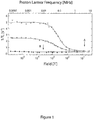
- Magnetic Resonance Imaging for medical and diagnostic applications is normally carried out at magnetic fields of at least 1 tesla (10,000 gauss), which corresponds to an RF frequency of 42 MHz for the nuclear magnetic resonance (NMR) signal of protons in water which is the major constituent of the body.
- NMR nuclear magnetic resonance
- the high field results in both better polarisation of the hydrogen nuclei and a strong signal at the higher detection frequency. This results in good contrast and spatial resolution.
- Whole body imaging at this field requires a large solenoid magnet, usually superconducting with high homogeneity typically a few parts per million over a 40 cm sphere.
- the patient/subject is placed on a bed which slides into the bore of the magnet. This can be a claustrophobic and unnerving experience. It is made worse due to the noisy operation of the gradient coils as images are acquired over a period of typically 15 minutes. As a result, as many as 20-40% of patients decline the procedure.
- the limit in using lower fields is set by the ability of the electronic amplifiers and the resonant detection circuits to detect the signals with an adequate signal to noise ratio.
- SQUID Superconducting Quantum Interference Device
- Squids are ideally suited to acquiring the very small NMR signals at low magnetic fields and thus allow the use of open geometry magnet systems, which have the potential to offer the patient a more friendly environment during the procedure as well as other benefits described below.
- the sample or the subject is placed in a magnetic field which results in a polarisation of hydrogen nuclei, with the result that more nuclei point in the direction of the field rather than against it.
- This polarisation is quite weak for protons in water. It corresponds to parts per million at room temperature at 1 tesla.
- RF radio frequency
- the energy of the tipped magnetisation is given up to the local environment. That is to say, the nuclear spins are exchanging energy with that local environment.
- the speed with which energy is exchanged is a measure of the interaction of the nuclei with the local environment.
- T1 tissue types and tissue conditions.
- the frequency at which this signal is detected is directly proportional to the local magnetic field.
- the signal frequency becomes dependant on position, with spins in higher fields precessing at higher frequencies to those in lower fields.
- a set of field gradients in all three dimensions a three-dimensional picture of the subject can be acquired.
- gradients across one plane are used to select a planar slice through the subject. This is then analysed by gradients of field in the plane of the slice to produce a two-dimensional picture of the subject in that plane.
- the magnitude of the gradient must be sufficient to disperse the spin frequencies by a sufficient amount to allow data to be acquired in the short time available, but not so large as to disperse and depress the detected signal.
- the background field must be uniform so that variations in the background field do not impinge on the image quality.
- figures might be for a 1 tesla magnet field a gradient of 1000 ppm or 1 mT across the subject, requiring a background homogeneity of 2-5 ppm. Building large magnets to accommodate a whole person with a field homogeneity of a few ppm over say a 400 mm sphere is an expensive and difficult task.
- the same field gradients for imaging are required. That is about 1 mT across the image area, since the same frequency changes are required. This means that the homogeneity of a magnet running at 0.02 tesla need only be 100 ppm, a figure which is much easier to achieve during magnet construction.
- the pre-polarising pulse is difficult to apply and secondly the technique is vulnerable to weak DC magnetic field disturbances which distort the image, as well as a susceptibility to RF and AF interference due to the direct DC coupling of the input coil to the SQUID.
- the technique would therefore normally have to be performed in a shielded room environment.
- An alternative technique is to use a resonant superconducting input circuit which is AC coupled to the SQUID input.
- No pre-polarising field is required and the use of a tuned AC coupled input greatly reduces the susceptibility to unwanted interference.
- This approach has been pioneered by Dr Hugh Seton at Aberdeen University.
- the present invention seeks to provide improved magnetic resonance apparatus and methods as well as a method of detecting tissue abnormalities in a patient or animal.
- MRI apparatus as in claim 8.
- the preferred embodiment of the present invention uses the resonant frequency SQUID-based MRI method and changes the procedure and pulse sequences so as to have enhanced T1 contrast.
- the device preferably does not employ an iron core.
- the field generated by the coils may or may not be pulsed.
- the differences in T1 between different tissues, or parts of the sample means that magnetisation will be lost or reduced in some parts of the sample so that the image is altered. Taking two images, one without the field being cycled and one with field cycling and comparing one image to the other will give an image highlighting the variations of T1. It is considered such images provide very good indications of abnormal human or animal tissues, particularly cancer bearing tissues.
- SQUID based MRI One great advantage of SQUID based MRI is that the magnetic fields are modest, which means that the stored energy of the field is small, allowing the field to be switched from one field level to another very quickly. This makes it possible to use the field switching technique described above.
- the operating current is about 100 A and the inductance of the coil set is 100 mH.
- a second advantage is that it allows the magnet to be a relatively open structure. Also, the field homogeneity and stability requirements are not so severe, making the magnet technology easier and the design more flexible.
- a system which can rely on a lower field intensity will be smaller, cheaper and require less operational energy.
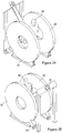
- FIGS 2A to 2F show a subject/patient 10 between two planar annular magnets 12, 14, with the SQUID detector in its own cryostat 16 placed close to the patient.
- the magnets 12, 14 are of a size and position that they allow space for the subject 10 to sit, lie or stand between them.
- the field is both low and switchable, it is also possible to consider manipulations and surgical operations to be performed without moving the patient 10 from the scanner.
- the physician can monitor the progress of a medical procedure using live scan results, which can provide significant clinical benefits.
- the planar windings (not visible in the Figures but of a type which will be evident to the skilled person) are cooled in a vacuum insulated cryostat which has either liquid cryogens or, preferably, a cryo-cooler 18 to maintain the windings in the superconducting state. About 4K is required for windings of NbTi but higher temperatures would be acceptable for advanced HTS conductors.
- the cryostats and coil sets are designed to have a low Johnson noise contribution from any metal parts.
- the tuned pick-up detection coils (not visible in the Figures but of a type which will be evident to the skilled person) and the SQUID are placed within a third cryostat.
- This cryostat is also designed to have a very low Johnson signal. Techniques for this are known in the art and for example described in the published works of Hugh Seton of Aberdeen University.
- the pick-up coil may be designed as a single turn or as an astatic reverse pair to increase the selectivity to signals close to the pick-up circuit, that is the subject 10. It is also possible to use an array of detector coils, each connected to a SQUID, as a set of parallel inputs to be amplified, detected and analysed.
- the input circuit is tuned to operate in the resonant NMR frequency range of 100 kHz or more, the input coil is AC coupled to the SQUID.
- Low frequency for example 50 Hz mains, and quasi DC signals from changes in the background field are not transmitted to the SQUID which would otherwise be saturated with unwanted signals.
- the NMR signal detected and amplified by the SQUID circuit is digitised and analysed by a conventional MRI console which will usually be controlled from a computer, which is also used to display the resultant images.
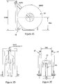
- Figure 3 is a side elevational view of another embodiment of MRI apparatus, viewed as a possible practical implementation of the device. It can be seen that there is provided an area within the MRI system for a patient to sit comfortably and in which the patient is not enclosed within the device, as occurs with prior art systems.
- FIG. 4 there is shown another practical implementation of the device, which in the views of Figure 4 , allows a patient to be scanned while in a standing position and within apparatus which is substantially open and thus less daunting to the patient compared with prior art scanning devices.
- a further advantage of a standing position is that for scans of patients with back pane and spinal problems it is very useful to observe the spine under load in the standing position. This will be quite different from an image taken with the patient lying down. It can be seen that the coils 12' and 14' are housed within the suitable chambers to provide an oligomeric and aesthetically pleasing structure.
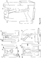
- FIG. 5 show the apparatus of Figure 4 when arranged for a patient lying on a bed or platform 20, in which case the cryostat probe 16' can be oriented to accommodate the patient in a lying position. Again, even when on a bed or platform, the patient is kept in a relatively open environment and one in which, as a result of the manner of operation of the device, does not generate excessive noise or other disturbance during operation of the system which could unsettle the patient.
- the low field is preferably much less than 50% of the main field intensity and in the preferred embodiments in the region or 10% or so.
- the embodiments described above are directed to a scanner into which a person can fit substantially entirely. It is envisaged that many practical implementations of the system and apparatus disclosed herein could be significantly smaller and designed, for instance, to scan and image only a portion of a patient.
- Systems could be provided, for instance, for breast cancer screening, liver screening, in the diagnosis of back pain and so on.
- the device could be physically smaller and may, for instance have coils no more than around 700 to 800 millimetres in diameter and even smaller.
- the apparatus would have no iron core and may or may not provide for field pulsing of the type disclosed above.
Landscapes
- Physics & Mathematics (AREA)
- Condensed Matter Physics & Semiconductors (AREA)
- General Physics & Mathematics (AREA)
- High Energy & Nuclear Physics (AREA)
- Spectroscopy & Molecular Physics (AREA)
- Electromagnetism (AREA)
- Magnetic Resonance Imaging Apparatus (AREA)
Claims (16)
- Procédé de détection IRM dans lequel l'excitation et la détection d'un signal RMN provenant d'un échantillon ou d'au moins une partie d'un sujet sont réalisées par un circuit résonnant d'entrée dans un champ magnétique au niveau d'un champ principal supérieur à environ 10 mT (=100 gauss), le champ magnétique étant cyclé à un champ faible inférieur à environ 50 % du champ principal, après l'excitation du signal RMN avec une première impulsion RF, durant une période de temps pendant laquelle des différences de magnétisation se développent en raison de différences de T1 entre différents tissus dans l'échantillon ou l'au moins une partie du sujet, et le champ magnétique étant renvoyé vers le champ principal pour permettre au signal RMN d'être détecté ; la première impulsion RF étant appliquée pendant un premier cycle du champ magnétique au niveau du champ principal et une seconde impulsion RF étant appliquée dans un second cycle du champ magnétique au niveau du champ principal, générant ainsi un écho de spin de la magnétisation dans le champ magnétique ; le signal RMN étant détecté par un SQUID.
- Procédé selon la revendication 1, dans lequel la première impulsion RF est sensiblement une impulsion à 90° et la seconde impulsion est sensiblement une impulsion à 180°.
- Procédé selon une quelconque revendication précédente, dans lequel le champ principal se trouve dans la région de 15 mT (=150 gauss).
- Procédé selon une quelconque revendication précédente, dans lequel le procédé comprend les étapes suivantes :générer une première image à partir du signal RMN,exciter et détecter un autre signal RMN à l'aide du circuit résonnant d'entrée selon le procédé de la revendication 1, si ce n'est que le champ magnétique n'est pas cyclé et reste au niveau du champ principal,générer une seconde image à partir de l'autre signal RMN, etcomparer la première image à la seconde image pour souligner des différences de T1 entre les différents tissus.
- Procédé selon une quelconque revendication précédente, dans lequel la période du champ faible est inférieure à 10 secondes, de préférence entre sensiblement 0,1 et 3 secondes.
- Procédé selon une quelconque revendication précédente, dans lequel le champ faible a une intensité de l'ordre de 10 % du champ principal.
- Procédé selon une quelconque revendication précédente, dans lequel un champ de polarisation d'arrière-plan est généré par une paire divisée de bobines supraconductrices ou d'enroulements plans supraconducteurs.
- Appareil IRM comprenant des première et seconde bobines disposées sensiblement l'une en face de l'autre, un circuit résonnant d'entrée apte à exciter et détecter un signal RMN dans un échantillon ou au moins une partie d'un sujet, et un système de commande configuré pour induire, par les bobines, un champ magnétique au niveau d'un champ principal supérieur à environ 10 mT (=100 gauss) et pour cycler le champ à un champ faible inférieur à environ 50 % du champ principal ; et, après l'excitation du signal RMN avec une première impulsion RF, durant une période de temps pendant laquelle des différences de magnétisation se développent en raison de différences de T1 entre différents tissus dans l'échantillon ou l'au moins une partie du sujet, pour renvoyer le champ magnétique vers le champ principal pour permettre au signal RMN d'être détecté ; ledit système de commande étant configuré pour appliquer la première impulsion RF pendant un premier cycle du champ magnétique au niveau du champ principal et une seconde impulsion RF dans un second cycle du champ magnétique au niveau du champ principal, générant ainsi un écho de spin de la magnétisation dans le champ magnétique ; l'appareil comprenant un SQUID pour détecter le signal RMN généré.
- Appareil IRM selon la revendication 8, dans lequel la première impulsion RF est sensiblement une impulsion à 90° et la seconde impulsion est sensiblement une impulsion à 180° et/ou le champ principal se trouve dans la région de 15 mT (=150 gauss).
- Appareil IRM selon l'une quelconque des revendications 8 à 9, dans lequel l'appareil est configuré pour générer une première image à partir du signal RMN, pour exciter et détecter un autre signal RMN à l'aide du circuit résonnant d'entrée, pour générer une seconde image à partir de l'autre signal RMN, et pour comparer la première image à la seconde image pour souligner des différences de T1 entre différents tissus ;
pour l'autre signal RMN, le système de commande est configuré tel que décrit dans la revendication 8, si ce n'est que, pour l'autre signal RMN, le système de commande est configuré pour ne pas cycler le champ magnétique et pour maintenir à la place le champ magnétique au niveau du champ principal. - Appareil IRM selon l'une quelconque des revendications 8 à 10, dans lequel la période de champ faible est comprise entre sensiblement 0,1 et 3 secondes.
- Appareil IRM selon l'une quelconque des revendications 8 à 11, dans lequel les première et seconde bobines sont une paire divisée de bobines supraconductrices ou d'enroulements plans supraconducteurs pour générer un champ de polarisation d'arrière-plan.
- Appareil IRM selon la revendication 12, dans lequel les première et seconde bobines sont enfermées dans un cryostat à faible bruit de Johnson réalisé à partir de matériaux non-métalliques.
- Appareil IRM selon la revendication 12 ou 13, dans lequel les première et seconde bobines sont refroidies de manière cryogénique.
- Appareil IRM selon l'une quelconque des revendications 8 à 14, dans lequel l'appareil fournit une zone ouverte pour un patient pendant un balayage et une imagerie.
- Procédé de détection d'anomalies dans un tissu dans au moins une partie d'un sujet, comprenant :utiliser le procédé selon la revendication 4 ou l'appareil selon la revendication 10 pour générer différentes images de ladite partie du sujet ; etcomparer lesdites différentes images pour détecter lesdites anomalies dans le tissu.
Applications Claiming Priority (2)
| Application Number | Priority Date | Filing Date | Title |
|---|---|---|---|
| GBGB0810322.8A GB0810322D0 (en) | 2008-06-05 | 2008-06-05 | Magnetic resonance imaging apparatus and method |
| PCT/GB2009/001390 WO2009147392A1 (fr) | 2008-06-05 | 2009-06-04 | Appareil et procédé d'imagerie par résonance magnétique et procédé utilisant la détection squid et le cyclage de champ |
Publications (2)
| Publication Number | Publication Date |
|---|---|
| EP2294437A1 EP2294437A1 (fr) | 2011-03-16 |
| EP2294437B1 true EP2294437B1 (fr) | 2019-04-10 |
Family
ID=39638255
Family Applications (1)
| Application Number | Title | Priority Date | Filing Date |
|---|---|---|---|
| EP09757764.7A Active EP2294437B1 (fr) | 2008-06-05 | 2009-06-04 | Appareil et procédé d'imagerie par résonance magnétique et procédé utilisant la détection squid et le cyclage de champ |
Country Status (6)
| Country | Link |
|---|---|
| US (1) | US8838200B2 (fr) |
| EP (1) | EP2294437B1 (fr) |
| JP (1) | JP5624028B2 (fr) |
| CN (1) | CN102084263B (fr) |
| GB (2) | GB0810322D0 (fr) |
| WO (1) | WO2009147392A1 (fr) |
Families Citing this family (12)
| Publication number | Priority date | Publication date | Assignee | Title |
|---|---|---|---|---|
| GB0810322D0 (en) * | 2008-06-05 | 2008-07-09 | Cryogenic Ltd | Magnetic resonance imaging apparatus and method |
| US8593141B1 (en) | 2009-11-24 | 2013-11-26 | Hypres, Inc. | Magnetic resonance system and method employing a digital squid |
| US8970217B1 (en) | 2010-04-14 | 2015-03-03 | Hypres, Inc. | System and method for noise reduction in magnetic resonance imaging |
| KR101310750B1 (ko) * | 2012-01-31 | 2013-09-24 | 한국표준과학연구원 | 생체자기공명 장치 및 그 측정 방법 |
| JP6173757B2 (ja) * | 2013-04-22 | 2017-08-02 | 住友重機械工業株式会社 | Mri装置 |
| CN105137374B (zh) * | 2014-06-03 | 2018-09-25 | 中国科学院上海微系统与信息技术研究所 | 一种超高分辨率的磁共振成像方法及装置 |
| JP6674958B2 (ja) | 2014-11-11 | 2020-04-01 | ハイパーファイン リサーチ,インコーポレイテッド | 低磁場磁気共鳴のためのパルス・シーケンス |
| KR101632278B1 (ko) * | 2015-01-15 | 2016-06-21 | 한국표준과학연구원 | 저 자기장 및 극저 자기장 핵자기 공명 및 자기 공명 영상 장치 |
| US10416253B2 (en) | 2016-11-22 | 2019-09-17 | Quantum Design International, Inc. | Conical access split magnet system |
| BR112020020580A2 (pt) * | 2018-04-20 | 2021-01-12 | Hyperfine Research, Inc. | Proteção posicionável para dispositivos de imageamento de ressonância magnética portáteis |
| TW202012951A (zh) | 2018-07-31 | 2020-04-01 | 美商超精細研究股份有限公司 | 低場漫射加權成像 |
| US11510588B2 (en) | 2019-11-27 | 2022-11-29 | Hyperfine Operations, Inc. | Techniques for noise suppression in an environment of a magnetic resonance imaging system |
Family Cites Families (3)
| Publication number | Priority date | Publication date | Assignee | Title |
|---|---|---|---|---|
| US4354499A (en) * | 1978-11-20 | 1982-10-19 | Damadian Raymond V | Apparatus and method for nuclear magnetic resonance scanning and mapping |
| NZ534963A (en) * | 2002-02-06 | 2006-02-24 | Univ California | SQUID Detected NMR and MRI at ultralow fields |
| GB0810322D0 (en) * | 2008-06-05 | 2008-07-09 | Cryogenic Ltd | Magnetic resonance imaging apparatus and method |
-
2008
- 2008-06-05 GB GBGB0810322.8A patent/GB0810322D0/en not_active Ceased
-
2009
- 2009-06-04 US US12/996,304 patent/US8838200B2/en active Active
- 2009-06-04 EP EP09757764.7A patent/EP2294437B1/fr active Active
- 2009-06-04 GB GB1020957.5A patent/GB2473565B/en active Active
- 2009-06-04 JP JP2011512198A patent/JP5624028B2/ja active Active
- 2009-06-04 WO PCT/GB2009/001390 patent/WO2009147392A1/fr active Application Filing
- 2009-06-04 CN CN200980121048.5A patent/CN102084263B/zh not_active Expired - Fee Related
Non-Patent Citations (1)
| Title |
|---|
| CARRAVETTA M ET AL: "Beyond the T1 limit: singlet nuclear spin states in low magnetic fields", PHYSICAL REVIEW LETTERS, AMERICAN PHYSICAL SOCIETY, US, vol. 92, no. 15, 16 April 2004 (2004-04-16), pages 153003/1 - 4, XP002298310, ISSN: 0031-9007, DOI: 10.1103/PHYSREVLETT.92.153003 * |
Also Published As
| Publication number | Publication date |
|---|---|
| EP2294437A1 (fr) | 2011-03-16 |
| GB2473565A (en) | 2011-03-16 |
| US20110190619A1 (en) | 2011-08-04 |
| GB201020957D0 (en) | 2011-01-26 |
| JP2011521760A (ja) | 2011-07-28 |
| CN102084263B (zh) | 2015-12-16 |
| GB2473565B (en) | 2013-01-23 |
| WO2009147392A1 (fr) | 2009-12-10 |
| JP5624028B2 (ja) | 2014-11-12 |
| GB0810322D0 (en) | 2008-07-09 |
| CN102084263A (zh) | 2011-06-01 |
| US8838200B2 (en) | 2014-09-16 |
Similar Documents
| Publication | Publication Date | Title |
|---|---|---|
| EP2294437B1 (fr) | Appareil et procédé d'imagerie par résonance magnétique et procédé utilisant la détection squid et le cyclage de champ | |
| US10509084B1 (en) | Magnetic resonance system and method employing a digital SQUID | |
| EP1474707B1 (fr) | Rmn detectee par squid et irm a champs ultra faibles | |
| Darrasse et al. | Perspectives with cryogenic RF probes in biomedical MRI | |
| US8305078B2 (en) | Method of performing MRI with an atomic magnetometer | |
| US7187169B2 (en) | NMR and MRI apparatus and method | |
| US4442404A (en) | Method and means for the noninvasive, local, in-vivo examination of endogeneous tissue, organs, bones, nerves and circulating blood on account of spin-echo techniques | |
| McDermott et al. | SQUID-detected magnetic resonance imaging in microtesla magnetic fields | |
| Busch et al. | Measurements of T1‐relaxation in ex vivo prostate tissue at 132 μT | |
| Savukov et al. | Magnetic-resonance imaging of the human brain with an atomic magnetometer | |
| Kathiravan et al. | A review on potential issues and challenges in MR imaging | |
| De Souza et al. | NMR and MRI obtained with high transition temperature dc SQUIDs | |
| WO2006052236A1 (fr) | Appareil a resonance magnetique nucleaire (rmn) et d'imagerie par resonance magnetique (irm) et procede impliquant un magnetometre a squid | |
| Crooks | An introduction to magnetic resonance imaging | |
| McIntyre | A Practical Guide to In Vivo MRS |
Legal Events
| Date | Code | Title | Description |
|---|---|---|---|
| PUAI | Public reference made under article 153(3) epc to a published international application that has entered the european phase |
Free format text: ORIGINAL CODE: 0009012 |
|
| 17P | Request for examination filed |
Effective date: 20101210 |
|
| AK | Designated contracting states |
Kind code of ref document: A1 Designated state(s): AT BE BG CH CY CZ DE DK EE ES FI FR GB GR HR HU IE IS IT LI LT LU LV MC MK MT NL NO PL PT RO SE SI SK TR |
|
| AX | Request for extension of the european patent |
Extension state: AL BA RS |
|
| DAX | Request for extension of the european patent (deleted) | ||
| 17Q | First examination report despatched |
Effective date: 20120717 |
|
| RIC1 | Information provided on ipc code assigned before grant |
Ipc: G01R 33/36 20060101ALI20180406BHEP Ipc: G01R 33/035 20060101ALI20180406BHEP Ipc: G01R 33/48 20060101AFI20180406BHEP Ipc: G01R 33/44 20060101ALI20180406BHEP Ipc: G01R 33/3815 20060101ALI20180406BHEP Ipc: G01N 24/08 20060101ALI20180406BHEP Ipc: G01R 33/32 20060101ALI20180406BHEP Ipc: G01R 33/38 20060101ALI20180406BHEP |
|
| GRAP | Despatch of communication of intention to grant a patent |
Free format text: ORIGINAL CODE: EPIDOSNIGR1 |
|
| STAA | Information on the status of an ep patent application or granted ep patent |
Free format text: STATUS: GRANT OF PATENT IS INTENDED |
|
| INTG | Intention to grant announced |
Effective date: 20180518 |
|
| GRAJ | Information related to disapproval of communication of intention to grant by the applicant or resumption of examination proceedings by the epo deleted |
Free format text: ORIGINAL CODE: EPIDOSDIGR1 |
|
| STAA | Information on the status of an ep patent application or granted ep patent |
Free format text: STATUS: EXAMINATION IS IN PROGRESS |
|
| GRAP | Despatch of communication of intention to grant a patent |
Free format text: ORIGINAL CODE: EPIDOSNIGR1 |
|
| STAA | Information on the status of an ep patent application or granted ep patent |
Free format text: STATUS: GRANT OF PATENT IS INTENDED |
|
| INTC | Intention to grant announced (deleted) | ||
| INTG | Intention to grant announced |
Effective date: 20181016 |
|
| GRAS | Grant fee paid |
Free format text: ORIGINAL CODE: EPIDOSNIGR3 |
|
| GRAA | (expected) grant |
Free format text: ORIGINAL CODE: 0009210 |
|
| STAA | Information on the status of an ep patent application or granted ep patent |
Free format text: STATUS: THE PATENT HAS BEEN GRANTED |
|
| AK | Designated contracting states |
Kind code of ref document: B1 Designated state(s): AT BE BG CH CY CZ DE DK EE ES FI FR GR HR HU IE IS IT LI LT LU LV MC MK MT NL NO PL PT RO SE SI SK TR |
|
| RBV | Designated contracting states (corrected) |
Designated state(s): AT BE BG CH CY CZ DE DK EE ES FI FR GR HR HU IE IS IT LI LT LU LV MC MK MT NL NO PL PT RO SE SI SK TR |
|
| REG | Reference to a national code |
Ref country code: CH Ref legal event code: EP Ref country code: AT Ref legal event code: REF Ref document number: 1119454 Country of ref document: AT Kind code of ref document: T Effective date: 20190415 |
|
| REG | Reference to a national code |
Ref country code: IE Ref legal event code: FG4D |
|
| REG | Reference to a national code |
Ref country code: DE Ref legal event code: R096 Ref document number: 602009057842 Country of ref document: DE |
|
| REG | Reference to a national code |
Ref country code: NL Ref legal event code: MP Effective date: 20190410 |
|
| REG | Reference to a national code |
Ref country code: LT Ref legal event code: MG4D |
|
| REG | Reference to a national code |
Ref country code: AT Ref legal event code: MK05 Ref document number: 1119454 Country of ref document: AT Kind code of ref document: T Effective date: 20190410 |
|
| PG25 | Lapsed in a contracting state [announced via postgrant information from national office to epo] |
Ref country code: NL Free format text: LAPSE BECAUSE OF FAILURE TO SUBMIT A TRANSLATION OF THE DESCRIPTION OR TO PAY THE FEE WITHIN THE PRESCRIBED TIME-LIMIT Effective date: 20190410 |
|
| PG25 | Lapsed in a contracting state [announced via postgrant information from national office to epo] |
Ref country code: ES Free format text: LAPSE BECAUSE OF FAILURE TO SUBMIT A TRANSLATION OF THE DESCRIPTION OR TO PAY THE FEE WITHIN THE PRESCRIBED TIME-LIMIT Effective date: 20190410 Ref country code: LT Free format text: LAPSE BECAUSE OF FAILURE TO SUBMIT A TRANSLATION OF THE DESCRIPTION OR TO PAY THE FEE WITHIN THE PRESCRIBED TIME-LIMIT Effective date: 20190410 Ref country code: PT Free format text: LAPSE BECAUSE OF FAILURE TO SUBMIT A TRANSLATION OF THE DESCRIPTION OR TO PAY THE FEE WITHIN THE PRESCRIBED TIME-LIMIT Effective date: 20190910 Ref country code: NO Free format text: LAPSE BECAUSE OF FAILURE TO SUBMIT A TRANSLATION OF THE DESCRIPTION OR TO PAY THE FEE WITHIN THE PRESCRIBED TIME-LIMIT Effective date: 20190710 Ref country code: HR Free format text: LAPSE BECAUSE OF FAILURE TO SUBMIT A TRANSLATION OF THE DESCRIPTION OR TO PAY THE FEE WITHIN THE PRESCRIBED TIME-LIMIT Effective date: 20190410 Ref country code: SE Free format text: LAPSE BECAUSE OF FAILURE TO SUBMIT A TRANSLATION OF THE DESCRIPTION OR TO PAY THE FEE WITHIN THE PRESCRIBED TIME-LIMIT Effective date: 20190410 Ref country code: FI Free format text: LAPSE BECAUSE OF FAILURE TO SUBMIT A TRANSLATION OF THE DESCRIPTION OR TO PAY THE FEE WITHIN THE PRESCRIBED TIME-LIMIT Effective date: 20190410 |
|
| PGFP | Annual fee paid to national office [announced via postgrant information from national office to epo] |
Ref country code: IT Payment date: 20190726 Year of fee payment: 11 |
|
| PG25 | Lapsed in a contracting state [announced via postgrant information from national office to epo] |
Ref country code: LV Free format text: LAPSE BECAUSE OF FAILURE TO SUBMIT A TRANSLATION OF THE DESCRIPTION OR TO PAY THE FEE WITHIN THE PRESCRIBED TIME-LIMIT Effective date: 20190410 Ref country code: PL Free format text: LAPSE BECAUSE OF FAILURE TO SUBMIT A TRANSLATION OF THE DESCRIPTION OR TO PAY THE FEE WITHIN THE PRESCRIBED TIME-LIMIT Effective date: 20190410 Ref country code: GR Free format text: LAPSE BECAUSE OF FAILURE TO SUBMIT A TRANSLATION OF THE DESCRIPTION OR TO PAY THE FEE WITHIN THE PRESCRIBED TIME-LIMIT Effective date: 20190711 Ref country code: BG Free format text: LAPSE BECAUSE OF FAILURE TO SUBMIT A TRANSLATION OF THE DESCRIPTION OR TO PAY THE FEE WITHIN THE PRESCRIBED TIME-LIMIT Effective date: 20190710 |
|
| PG25 | Lapsed in a contracting state [announced via postgrant information from national office to epo] |
Ref country code: IS Free format text: LAPSE BECAUSE OF FAILURE TO SUBMIT A TRANSLATION OF THE DESCRIPTION OR TO PAY THE FEE WITHIN THE PRESCRIBED TIME-LIMIT Effective date: 20190810 Ref country code: AT Free format text: LAPSE BECAUSE OF FAILURE TO SUBMIT A TRANSLATION OF THE DESCRIPTION OR TO PAY THE FEE WITHIN THE PRESCRIBED TIME-LIMIT Effective date: 20190410 |
|
| REG | Reference to a national code |
Ref country code: DE Ref legal event code: R097 Ref document number: 602009057842 Country of ref document: DE |
|
| PG25 | Lapsed in a contracting state [announced via postgrant information from national office to epo] |
Ref country code: MC Free format text: LAPSE BECAUSE OF FAILURE TO SUBMIT A TRANSLATION OF THE DESCRIPTION OR TO PAY THE FEE WITHIN THE PRESCRIBED TIME-LIMIT Effective date: 20190410 Ref country code: CZ Free format text: LAPSE BECAUSE OF FAILURE TO SUBMIT A TRANSLATION OF THE DESCRIPTION OR TO PAY THE FEE WITHIN THE PRESCRIBED TIME-LIMIT Effective date: 20190410 Ref country code: SK Free format text: LAPSE BECAUSE OF FAILURE TO SUBMIT A TRANSLATION OF THE DESCRIPTION OR TO PAY THE FEE WITHIN THE PRESCRIBED TIME-LIMIT Effective date: 20190410 Ref country code: RO Free format text: LAPSE BECAUSE OF FAILURE TO SUBMIT A TRANSLATION OF THE DESCRIPTION OR TO PAY THE FEE WITHIN THE PRESCRIBED TIME-LIMIT Effective date: 20190410 Ref country code: DK Free format text: LAPSE BECAUSE OF FAILURE TO SUBMIT A TRANSLATION OF THE DESCRIPTION OR TO PAY THE FEE WITHIN THE PRESCRIBED TIME-LIMIT Effective date: 20190410 Ref country code: EE Free format text: LAPSE BECAUSE OF FAILURE TO SUBMIT A TRANSLATION OF THE DESCRIPTION OR TO PAY THE FEE WITHIN THE PRESCRIBED TIME-LIMIT Effective date: 20190410 |
|
| REG | Reference to a national code |
Ref country code: CH Ref legal event code: PL |
|
| PLBE | No opposition filed within time limit |
Free format text: ORIGINAL CODE: 0009261 |
|
| STAA | Information on the status of an ep patent application or granted ep patent |
Free format text: STATUS: NO OPPOSITION FILED WITHIN TIME LIMIT |
|
| 26N | No opposition filed |
Effective date: 20200113 |
|
| REG | Reference to a national code |
Ref country code: BE Ref legal event code: MM Effective date: 20190630 |
|
| PG25 | Lapsed in a contracting state [announced via postgrant information from national office to epo] |
Ref country code: TR Free format text: LAPSE BECAUSE OF FAILURE TO SUBMIT A TRANSLATION OF THE DESCRIPTION OR TO PAY THE FEE WITHIN THE PRESCRIBED TIME-LIMIT Effective date: 20190410 |
|
| PG25 | Lapsed in a contracting state [announced via postgrant information from national office to epo] |
Ref country code: IE Free format text: LAPSE BECAUSE OF NON-PAYMENT OF DUE FEES Effective date: 20190604 |
|
| PG25 | Lapsed in a contracting state [announced via postgrant information from national office to epo] |
Ref country code: LI Free format text: LAPSE BECAUSE OF NON-PAYMENT OF DUE FEES Effective date: 20190630 Ref country code: LU Free format text: LAPSE BECAUSE OF NON-PAYMENT OF DUE FEES Effective date: 20190604 Ref country code: BE Free format text: LAPSE BECAUSE OF NON-PAYMENT OF DUE FEES Effective date: 20190630 Ref country code: CH Free format text: LAPSE BECAUSE OF NON-PAYMENT OF DUE FEES Effective date: 20190630 Ref country code: SI Free format text: LAPSE BECAUSE OF FAILURE TO SUBMIT A TRANSLATION OF THE DESCRIPTION OR TO PAY THE FEE WITHIN THE PRESCRIBED TIME-LIMIT Effective date: 20190410 |
|
| PG25 | Lapsed in a contracting state [announced via postgrant information from national office to epo] |
Ref country code: CY Free format text: LAPSE BECAUSE OF FAILURE TO SUBMIT A TRANSLATION OF THE DESCRIPTION OR TO PAY THE FEE WITHIN THE PRESCRIBED TIME-LIMIT Effective date: 20190410 |
|
| PG25 | Lapsed in a contracting state [announced via postgrant information from national office to epo] |
Ref country code: HU Free format text: LAPSE BECAUSE OF FAILURE TO SUBMIT A TRANSLATION OF THE DESCRIPTION OR TO PAY THE FEE WITHIN THE PRESCRIBED TIME-LIMIT; INVALID AB INITIO Effective date: 20090604 Ref country code: MT Free format text: LAPSE BECAUSE OF FAILURE TO SUBMIT A TRANSLATION OF THE DESCRIPTION OR TO PAY THE FEE WITHIN THE PRESCRIBED TIME-LIMIT Effective date: 20190410 |
|
| PG25 | Lapsed in a contracting state [announced via postgrant information from national office to epo] |
Ref country code: IT Free format text: LAPSE BECAUSE OF NON-PAYMENT OF DUE FEES Effective date: 20200604 |
|
| PG25 | Lapsed in a contracting state [announced via postgrant information from national office to epo] |
Ref country code: MK Free format text: LAPSE BECAUSE OF FAILURE TO SUBMIT A TRANSLATION OF THE DESCRIPTION OR TO PAY THE FEE WITHIN THE PRESCRIBED TIME-LIMIT Effective date: 20190410 |
|
| PGFP | Annual fee paid to national office [announced via postgrant information from national office to epo] |
Ref country code: FR Payment date: 20230630 Year of fee payment: 15 Ref country code: DE Payment date: 20230630 Year of fee payment: 15 |