EP2294019B1 - Alimentation de brûleur à oxygène chaud - Google Patents
Alimentation de brûleur à oxygène chaud Download PDFInfo
- Publication number
- EP2294019B1 EP2294019B1 EP09772409.0A EP09772409A EP2294019B1 EP 2294019 B1 EP2294019 B1 EP 2294019B1 EP 09772409 A EP09772409 A EP 09772409A EP 2294019 B1 EP2294019 B1 EP 2294019B1
- Authority
- EP
- European Patent Office
- Prior art keywords
- oxygen
- fuel
- injection
- process according
- hot
- Prior art date
- Legal status (The legal status is an assumption and is not a legal conclusion. Google has not performed a legal analysis and makes no representation as to the accuracy of the status listed.)
- Active
Links
Images


Classifications
-
- C—CHEMISTRY; METALLURGY
- C03—GLASS; MINERAL OR SLAG WOOL
- C03B—MANUFACTURE, SHAPING, OR SUPPLEMENTARY PROCESSES
- C03B5/00—Melting in furnaces; Furnaces so far as specially adapted for glass manufacture
- C03B5/16—Special features of the melting process; Auxiliary means specially adapted for glass-melting furnaces
- C03B5/235—Heating the glass
-
- F—MECHANICAL ENGINEERING; LIGHTING; HEATING; WEAPONS; BLASTING
- F23—COMBUSTION APPARATUS; COMBUSTION PROCESSES
- F23D—BURNERS
- F23D14/00—Burners for combustion of a gas, e.g. of a gas stored under pressure as a liquid
- F23D14/32—Burners for combustion of a gas, e.g. of a gas stored under pressure as a liquid using a mixture of gaseous fuel and pure oxygen or oxygen-enriched air
-
- C—CHEMISTRY; METALLURGY
- C03—GLASS; MINERAL OR SLAG WOOL
- C03B—MANUFACTURE, SHAPING, OR SUPPLEMENTARY PROCESSES
- C03B5/00—Melting in furnaces; Furnaces so far as specially adapted for glass manufacture
- C03B5/16—Special features of the melting process; Auxiliary means specially adapted for glass-melting furnaces
- C03B5/235—Heating the glass
- C03B5/2353—Heating the glass by combustion with pure oxygen or oxygen-enriched air, e.g. using oxy-fuel burners or oxygen lances
-
- F—MECHANICAL ENGINEERING; LIGHTING; HEATING; WEAPONS; BLASTING
- F23—COMBUSTION APPARATUS; COMBUSTION PROCESSES
- F23C—METHODS OR APPARATUS FOR COMBUSTION USING FLUID FUEL OR SOLID FUEL SUSPENDED IN A CARRIER GAS OR AIR
- F23C6/00—Combustion apparatus characterised by the combination of two or more combustion chambers or combustion zones, e.g. for staged combustion
- F23C6/04—Combustion apparatus characterised by the combination of two or more combustion chambers or combustion zones, e.g. for staged combustion in series connection
- F23C6/045—Combustion apparatus characterised by the combination of two or more combustion chambers or combustion zones, e.g. for staged combustion in series connection with staged combustion in a single enclosure
-
- F—MECHANICAL ENGINEERING; LIGHTING; HEATING; WEAPONS; BLASTING
- F23—COMBUSTION APPARATUS; COMBUSTION PROCESSES
- F23D—BURNERS
- F23D14/00—Burners for combustion of a gas, e.g. of a gas stored under pressure as a liquid
- F23D14/20—Non-premix gas burners, i.e. in which gaseous fuel is mixed with combustion air on arrival at the combustion zone
- F23D14/22—Non-premix gas burners, i.e. in which gaseous fuel is mixed with combustion air on arrival at the combustion zone with separate air and gas feed ducts, e.g. with ducts running parallel or crossing each other
-
- F—MECHANICAL ENGINEERING; LIGHTING; HEATING; WEAPONS; BLASTING
- F23—COMBUSTION APPARATUS; COMBUSTION PROCESSES
- F23L—SUPPLYING AIR OR NON-COMBUSTIBLE LIQUIDS OR GASES TO COMBUSTION APPARATUS IN GENERAL ; VALVES OR DAMPERS SPECIALLY ADAPTED FOR CONTROLLING AIR SUPPLY OR DRAUGHT IN COMBUSTION APPARATUS; INDUCING DRAUGHT IN COMBUSTION APPARATUS; TOPS FOR CHIMNEYS OR VENTILATING SHAFTS; TERMINALS FOR FLUES
- F23L15/00—Heating of air supplied for combustion
- F23L15/04—Arrangements of recuperators
-
- F—MECHANICAL ENGINEERING; LIGHTING; HEATING; WEAPONS; BLASTING
- F23—COMBUSTION APPARATUS; COMBUSTION PROCESSES
- F23L—SUPPLYING AIR OR NON-COMBUSTIBLE LIQUIDS OR GASES TO COMBUSTION APPARATUS IN GENERAL ; VALVES OR DAMPERS SPECIALLY ADAPTED FOR CONTROLLING AIR SUPPLY OR DRAUGHT IN COMBUSTION APPARATUS; INDUCING DRAUGHT IN COMBUSTION APPARATUS; TOPS FOR CHIMNEYS OR VENTILATING SHAFTS; TERMINALS FOR FLUES
- F23L7/00—Supplying non-combustible liquids or gases, other than air, to the fire, e.g. oxygen, steam
- F23L7/007—Supplying oxygen or oxygen-enriched air
-
- Y—GENERAL TAGGING OF NEW TECHNOLOGICAL DEVELOPMENTS; GENERAL TAGGING OF CROSS-SECTIONAL TECHNOLOGIES SPANNING OVER SEVERAL SECTIONS OF THE IPC; TECHNICAL SUBJECTS COVERED BY FORMER USPC CROSS-REFERENCE ART COLLECTIONS [XRACs] AND DIGESTS
- Y02—TECHNOLOGIES OR APPLICATIONS FOR MITIGATION OR ADAPTATION AGAINST CLIMATE CHANGE
- Y02E—REDUCTION OF GREENHOUSE GAS [GHG] EMISSIONS, RELATED TO ENERGY GENERATION, TRANSMISSION OR DISTRIBUTION
- Y02E20/00—Combustion technologies with mitigation potential
- Y02E20/34—Indirect CO2mitigation, i.e. by acting on non CO2directly related matters of the process, e.g. pre-heating or heat recovery
-
- Y—GENERAL TAGGING OF NEW TECHNOLOGICAL DEVELOPMENTS; GENERAL TAGGING OF CROSS-SECTIONAL TECHNOLOGIES SPANNING OVER SEVERAL SECTIONS OF THE IPC; TECHNICAL SUBJECTS COVERED BY FORMER USPC CROSS-REFERENCE ART COLLECTIONS [XRACs] AND DIGESTS
- Y02—TECHNOLOGIES OR APPLICATIONS FOR MITIGATION OR ADAPTATION AGAINST CLIMATE CHANGE
- Y02P—CLIMATE CHANGE MITIGATION TECHNOLOGIES IN THE PRODUCTION OR PROCESSING OF GOODS
- Y02P40/00—Technologies relating to the processing of minerals
- Y02P40/50—Glass production, e.g. reusing waste heat during processing or shaping
Definitions
- the present invention relates to the implementation of burners operating with oxygen brought to a high temperature and fuels in the gaseous or liquid state. Burners of this type are intended in particular, but not exclusively, for use in glass melting furnaces.
- the combustion mode using oxygen or an oxygen-rich gas (at least 85% oxygen) is called "oxy-combustion”.
- the oxy-combustion compared to the aero-combustion, thus using air, allows an energy gain at least for the reason that the energy of the combustion gases is not absorbed in part by the nitrogen of l 'air.
- the fumes finally discharged, including nitrogen still entail a significant part.
- the reduction in energy consumption per unit of production considered has the additional advantage of limiting carbon dioxide emissions, and therefore of promoting compliance with regulatory requirements in this area.
- the inventors have first of all found that the delivery of hot oxygen requires the use of specific means.
- the eminently corrosive nature of hot oxygen leads to limiting its circulation to as short journeys as possible. It is also advisable to avoid the impact of the flow of oxygen in pipes having excessively curvatures. It is still desirable to avoid all surface irregularities in the path of this gas.
- the connections are preferably made by welding with a polished surface of these welds.
- the inventors propose to configure the burners so that the means for introducing the fuels can be the object of these maintenance operations, without it being necessary to intervene on those of the hot oxygen.
- the invention proposes to implement the method according to claim 1.
- the details of the elements of this method are the subject of the remainder of this description, and these details are the subject of subsidiary claims.
- the mode of supply of the burners according to the invention generally comprises, on the one hand, fuel supply means, means which are combined with an essentially unheated oxygen supply, and, on the other hand, supply means in hot oxygen independent of the former.
- the fraction of unheated oxygen should be kept as low as possible.
- the fuel and the hot oxygen are introduced separately into the burner, in other words at separate points even if the distance remains modest, it is necessary to provide a fraction of the oxygen to maintain and stabilize the flame at the fuel injection level.
- the proportion of oxygen relative to the assembly necessary for total combustion is very low. In all cases, this fraction is less than 10% of all the oxygen consumed by the burner considered.
- this proportion is between 1.5 and 7% of all the oxygen necessary to ensure complete combustion of the fuel.
- oxygen is in the essentially ambient temperature conditions which prevail on its path leading it towards the furnace.
- the temperature of the oxygen is preferably ambient temperature and must not exceed one hundred degrees, the temperature in the vicinity of the furnace being nevertheless significantly higher than that of the atmosphere at a distance from the furnace.
- the introduction into the furnace of this fraction of unheated oxygen must take place in the immediate vicinity of that of the fuel, or better this introduction must be simultaneous.
- the fuel and the hot oxygen are nevertheless conveyed in separate pipes to the ignition point which is located near the internal wall of the furnace.
- the end of the fuel injector is set back slightly in the refractory wall so as not to bring this end to too high a temperature, and to avoid the formation of deposits by cracking of the fuel and / or the degradation of the fuel. end of the injectors.
- this hot oxygen can be done in the vicinity of the introduction of the fuel insofar as the pipes remain distinct, in order to be able to intervene on those of fuel without touching those of hot oxygen.
- This technique is known in principle. It is referred to as "staged combustion”.
- staged combustion is to limit the highest temperature reached in the flame, by distributing the combustion over its length by the progressive supply of oxygen.
- Such a gradual supply is obtained in particular by carrying out the introduction of oxygen into the furnace at a distance from the injection of the fuel. In this way the gas flows meet after advancing inside the oven, away from the wall on which the burner is located.
- the quantities of oxygen used are advantageously d 'all the more important as they enter this stream further downstream in the flame.
- admission points are necessarily few. They are advantageously arranged so symmetrical about the fuel introduction point so that the flame also develops symmetrically.
- the number of hot oxygen admissions on either side of the point of introduction of the fuel does not exceed three and preferably is equal to two.
- the proportions of oxygen introduced as indicated are advantageously greater by moving away from the point of introduction of the fuel.
- the ratio of the quantities introduced at two consecutive points whose distance from the point of introduction of the fuel increases is preferably Q n / Q n + 1 ⁇ 1, and advantageously such that 0.2 ⁇ Q n / Q n + 1 ⁇ 0.6.
- the adjustment of the quantities of hot oxygen is preferably obtained without interposing elements such as valves whose members are liable to be rapidly corroded.
- the proportions distributed are determined by nozzles of appropriate dimensions arranged upstream of the introduction into the burner, and downstream of the heat exchanger in which the oxygen is heated.
- the arrangement of the burner comprising a single fuel injection requires the interruption of the burner. This interruption does not compromise the operation of the oven when it has a high number of burners, and the interrupted energy supply, which represents only a fraction of the whole, can even be compensated if necessary by the momentary increase in the speed of neighboring burners. The energy distribution is then only slightly displaced in the space of the oven.
- burners comprising more than one fuel injection point, and in particular two points.
- these burners generally follows the process described above with regard to burners having only one point of introduction. Under normal conditions, the two injectors are then advantageously in simultaneous operation and preferably each contribute half to the supply of fuel. During maintenance operations, one of the injectors can be interrupted while the other remains in operation and its speed possibly modified to compensate for all or part of the contribution from the interrupted injector. Once the first injector has been repaired, the process is repeated on the second. Under these conditions the burner can deliver a power which is little, or not modified compared to that corresponding to ordinary operation.
- the fuel introductions are intended for the same fuel. It is also possible to have on the same burner two or more, supplied with fuel for different types of fuel, in particular gaseous fuels on the one hand and liquid fuels such as heavy fuels, on the other hand.
- burners capable of operating with different types of fuel is first of all linked to the qualities of these combustibles.
- natural gas for example is known to lead to an increased water content in the atmosphere of the furnace compared to what is obtained for example with heavy fuel oil.
- the nature of this atmosphere is an element which directly influences the refining process and the water content of the glass produced.
- the choice of fuel is therefore an important element of the whole.
- the burner of FIG. 1 a comprises a refractory block 1 which enters into the constitution of the wall of the furnace.
- This block is advantageously made up of several parts assembled to each other by an armature, not shown, situated on the outside with respect to the oven.
- the refractory block is traversed by several pipes which open onto the internal face of the furnace and which allow the introduction of fuel and oxygen.
- the arrangement of the various supply lines depends on the desired combustion regime on the one hand, and on the general shape of the flame on the other.
- staged combustion One technique for limiting temperatures is to have the fuel gradually come into contact with the oxidant.
- the diet is usually referred to as "staged combustion".
- the flame is successively supplied with oxygen by mixing this primary flame with the jets of oxygen emitted from the injection nozzles situated on the wall at a certain distance from the nozzle.
- injection of fuel and primary oxygen are arranged according to the characteristics of the gas flows (flow rate, emission speed, temperature), the expansion of these and the length of the desired flame.
- the fuel supply is shown diagrammatically by the pipe 2.
- This pipe is concentric with the pipe 3 supplying the primary oxygen.
- the assembly is arranged in the center of the burner.
- the distribution of oxygen on the pipes is advantageously such that the quantity increases with the distance which separates its injection point from that of the fuel.
- the supplies via the pipes 4 are advantageously less important than those supplied from the pipes 5.
- the ratio of the respective supply via the lines 4 (Q 1 ) and 5 (Q 2 ) is for example between 0.2 and 0.6.
- a flat flame is advantageous in the case of glass melting furnaces. It makes it possible to directly expose the largest possible surface of the bath to radiation from the flame, or indirectly that of the refractories exposed to this flame, in particular those of the roof of the furnace.
- the layout of the injections can be significantly different when the shape of the flame is not controlled by heat exchange with a flat surface.
- the supplies can in particular be arranged concentrically around the primary injection point.
- An alternative solution to minimize the influences of maintenance operations lies for example in the use of burners comprising two fuel injections.
- the two injections are then used simultaneously.
- one of these injection means is temporarily interrupted.
- the second injection takes over from part or all of the supply corresponding to that of the injector when stopped.
- the second can in turn be subject to maintenance.
- the most usual consists of removing the fuel injection lance from the refractory block through which it enters the furnace.
- the cleared opening is temporarily blocked to prevent the ingress of air.
- Fuel supplies generally do not require pipes offering particular characteristics of corrosion resistance. Usual materials such as traditional stainless steels are sufficient, and above all these pipes can support fittings, valves and other elements capable of being dismantled during these maintenance operations.
- oxygen conduits must have very specific resistance qualities and it is necessary as far as possible to avoid or reduce as much as possible the welds or the connecting elements. For this reason, the hot oxygen supply lines are generally kept in place during maintenance operations.
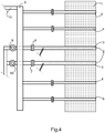
- the figures 3 and 4 take over the elements of the burners Figures 1 and 2 , by incorporating additional elements of hot oxygen supply.
- the pipes 4 and 5 are connected to a feeder 6. Between the feeder 6 and the burner, the presence of a valve is avoided. The distance between the nurse and the burner is also as short as the space required near the oven allows.
- the pipes shown straight may have curvatures. It is preferable that these curvatures are as little accentuated as possible to minimize the impact of hot oxygen on their walls, which, in the long term, is likely to cause their erosion.
- the quantity of oxygen distributed over each pipeline is permanently determined by the dimensions of the nozzles located either on the pipelines or at the junction of the pipelines 4 and 5 with the manifold 6.
- the nurse is for its part supplied by a pipe 19 which is connected to a heat exchanger, not shown in these figures, exchanger in which the oxygen is heated. Lack of power interpose valves on the hot oxygen path, changes in speed are controlled from the cold oxygen introduced into the exchanger. These modifications are necessarily limited.
- the cold fuel and oxygen supplies shown in the figures 3 and 4 consist of the line 3.
- This line 3 surrounds the fuel line 2.
- These two lines can be separated from their respective supply circuit, at the flanges 7 and 8. Once these flanges are defeated, the lines 2 and 3 can be extracted from the refractory to proceed with their restoration.
- the figures 2 and 3 schematically show the arrangement which may be that in which the fuel passing through the central pipe 2 is gaseous.
- the fuel is liquid, its introduction requires the use of means allowing the atomization of this liquid.
- the fuel supply line must also include a supply line for this atomization gas up to near the injection.
- the "cold" oxygen supply via the pipes 3 can be regulated separately for example by means of the valves 9 and 10.
- each exchanger does not feed more than two burners, and in a particularly preferred manner each exchanger is connected only to one burner. In this way the oxygen flow can be adjusted for each burner independently of the other burners, and the adjustment can be made on the oxygen before it passes through the heat exchanger.
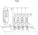
- the figure 5 shows schematically an oxygen supply assembly for an oven, for example intended for the melting of glass materials.
- the oven 11 is partially shown in top view. Its side refractory wall 12 carries a series of schematic burners 13 inserted in the wall. Each burner 13 is supplied in two ways with oxygen. A first series of pipes 14 routes cold oxygen as specified above, to supply the primary combustion. A second series of pipes 15 supplies the heat exchangers 16. At the outlet of these exchangers the hot oxygen is transported to the burners by pipes 17 generally representing the different hot oxygen supplies of each burner.
- the heat exchangers 16 circulate against the flow of oxygen a heat transfer fluid previously heated.
- the heating of this heat transfer fluid is conducted in a recuperator 18 in which the fumes F leaving the furnace 11 circulate.
- a first "recuperator" 18 the fumes heat the intermediate fluid, for example air, nitrogen, CO 2 or any suitable fluid which circulates for example in a loop between this recuperator and the exchangers 16 in which it heats oxygen.
- the intermediate fluid for example air, nitrogen, CO 2 or any suitable fluid which circulates for example in a loop between this recuperator and the exchangers 16 in which it heats oxygen.
- An alternative for the intermediate fluid such as air, is not to use the loop and to recover the hot air at the outlet of the secondary exchangers by a boiler or other means of energy recovery.
Landscapes
- Engineering & Computer Science (AREA)
- Chemical & Material Sciences (AREA)
- Combustion & Propulsion (AREA)
- Mechanical Engineering (AREA)
- General Engineering & Computer Science (AREA)
- Materials Engineering (AREA)
- Organic Chemistry (AREA)
- Combustion Of Fluid Fuel (AREA)
- Glass Melting And Manufacturing (AREA)
Priority Applications (1)
| Application Number | Priority Date | Filing Date | Title |
|---|---|---|---|
| EP09772409.0A EP2294019B1 (fr) | 2008-07-02 | 2009-06-30 | Alimentation de brûleur à oxygène chaud |
Applications Claiming Priority (3)
| Application Number | Priority Date | Filing Date | Title |
|---|---|---|---|
| EP08104609 | 2008-07-02 | ||
| EP09772409.0A EP2294019B1 (fr) | 2008-07-02 | 2009-06-30 | Alimentation de brûleur à oxygène chaud |
| PCT/EP2009/058139 WO2010000709A1 (fr) | 2008-07-02 | 2009-06-30 | Alimentation de brûleur à oxygène chaud |
Publications (2)
| Publication Number | Publication Date |
|---|---|
| EP2294019A1 EP2294019A1 (fr) | 2011-03-16 |
| EP2294019B1 true EP2294019B1 (fr) | 2020-04-01 |
Family
ID=40120169
Family Applications (1)
| Application Number | Title | Priority Date | Filing Date |
|---|---|---|---|
| EP09772409.0A Active EP2294019B1 (fr) | 2008-07-02 | 2009-06-30 | Alimentation de brûleur à oxygène chaud |
Country Status (9)
| Country | Link |
|---|---|
| US (1) | US9841188B2 (enExample) |
| EP (1) | EP2294019B1 (enExample) |
| JP (1) | JP5564041B2 (enExample) |
| KR (1) | KR101642162B1 (enExample) |
| CN (1) | CN102076620B (enExample) |
| BR (1) | BRPI0913941A2 (enExample) |
| EA (1) | EA020395B1 (enExample) |
| MX (1) | MX2010014204A (enExample) |
| WO (1) | WO2010000709A1 (enExample) |
Families Citing this family (12)
| Publication number | Priority date | Publication date | Assignee | Title |
|---|---|---|---|---|
| BE1019569A3 (fr) * | 2010-11-08 | 2012-08-07 | Agc Glass Europe | Bruleur. |
| US9618203B2 (en) * | 2012-09-26 | 2017-04-11 | L'Air Liquide Société Anonyme Pour L'Étude Et L'Eploitation Des Procedes Georges Claude | Method and system for heat recovery from products of combustion and charge heating installation including the same |
| US20140162205A1 (en) * | 2012-12-10 | 2014-06-12 | American Air Liquide, Inc. | Preheating oxygen for injection into blast furnaces |
| FR3002025B1 (fr) * | 2013-02-12 | 2015-02-20 | Air Liquide | Methode de combustion dans un four avec recuperation de chaleur |
| US9828275B2 (en) | 2013-06-28 | 2017-11-28 | American Air Liquide, Inc. | Method and heat exchange system utilizing variable partial bypass |
| FR3015635B1 (fr) * | 2013-12-23 | 2019-05-31 | L'air Liquide, Societe Anonyme Pour L'etude Et L'exploitation Des Procedes Georges Claude | Procede integre d'oxycombustion et de production d'oxygene |
| DE102014002074A1 (de) * | 2014-02-14 | 2015-08-20 | Messer Austria Gmbh | Verfahren und Vorrichtung zur in-situ Nachverbrennung von bei einem Verbrennungsvorgang erzeugten Schadstoffen |
| CN106116109A (zh) * | 2016-06-22 | 2016-11-16 | 巨石集团有限公司 | 一种玻璃池窑及玻璃熔制的方法 |
| JP6999186B2 (ja) * | 2016-11-22 | 2022-01-18 | アイシー リミテッド ライアビリティ カンパニー | 点火プラグ燃焼イオン化センサ |
| US10584051B2 (en) * | 2017-02-22 | 2020-03-10 | Air Products And Chemicals, Inc. | Double-staged oxy-fuel burner |
| TWI776333B (zh) * | 2019-12-31 | 2022-09-01 | 法國商液態空氣喬治斯克勞帝方法研究開發股份有限公司 | 用於燃料燃燒的燃燒器及其燃燒方法 |
| CN112815308B (zh) * | 2020-12-31 | 2021-12-17 | 长沙广钢气体有限公司 | 一种熔炼反射炉用纯氧燃烧装置及燃烧方法 |
Family Cites Families (13)
| Publication number | Priority date | Publication date | Assignee | Title |
|---|---|---|---|---|
| US5984667A (en) * | 1995-07-17 | 1999-11-16 | American Air Liquide, Inc. | Combustion process and apparatus therefore containing separate injection of fuel and oxidant streams |
| US5807418A (en) * | 1996-05-21 | 1998-09-15 | Praxair Technology, Inc. | Energy recovery in oxygen-fired glass melting furnaces |
| US6126438A (en) * | 1999-06-23 | 2000-10-03 | American Air Liquide | Preheated fuel and oxidant combustion burner |
| US6699029B2 (en) * | 2001-01-11 | 2004-03-02 | Praxair Technology, Inc. | Oxygen enhanced switching to combustion of lower rank fuels |
| US6869277B2 (en) * | 2002-03-16 | 2005-03-22 | Exxonmobil Chemical Patents Inc. | Burner employing cooled flue gas recirculation |
| FR2853953B1 (fr) | 2003-04-18 | 2007-02-09 | Air Liquide | Procede de combustion etagee d'un combustible liquide et d'un oxydant dans un four |
| FR2863689B1 (fr) * | 2003-12-16 | 2006-05-05 | Air Liquide | Procede de combustion etagee mettant en oeuvre un oxydant prechauffe |
| FR2863692B1 (fr) * | 2003-12-16 | 2009-07-10 | Air Liquide | Procede de combustion etagee avec injection optimisee de l'oxydant primaire |
| FR2863690B1 (fr) * | 2003-12-16 | 2006-01-20 | Air Liquide | Procede de combustion etagee mettant en oeuvre un gaz riche en oxygene et un gaz pauvre en oxygene |
| FR2879283B1 (fr) * | 2004-12-13 | 2007-01-19 | Air Liquide | Procede de combustion avec alimentation cyclique du comburant |
| DE102005005832B4 (de) | 2005-02-08 | 2006-11-02 | Air Liquide Deutschland Gmbh | Rekuperatorbrenner und Verfahren zum Erhitzen eines Industrieofens unter Einsatz des Brenners |
| FR2895490B1 (fr) | 2005-12-22 | 2008-03-14 | Air Liquide | Procede d'oxycombustion etagee mettant en oeuvre des reactifs prechauffes |
| KR100820233B1 (ko) * | 2006-10-31 | 2008-04-08 | 한국전력공사 | 연소기 및 이를 포함하는 멀티 연소기, 그리고 연소방법 |
-
2009
- 2009-06-30 JP JP2011515418A patent/JP5564041B2/ja active Active
- 2009-06-30 CN CN200980124995.XA patent/CN102076620B/zh active Active
- 2009-06-30 US US12/999,918 patent/US9841188B2/en active Active
- 2009-06-30 BR BRPI0913941A patent/BRPI0913941A2/pt not_active Application Discontinuation
- 2009-06-30 EA EA201100130A patent/EA020395B1/ru not_active IP Right Cessation
- 2009-06-30 KR KR1020117002482A patent/KR101642162B1/ko not_active Expired - Fee Related
- 2009-06-30 EP EP09772409.0A patent/EP2294019B1/fr active Active
- 2009-06-30 WO PCT/EP2009/058139 patent/WO2010000709A1/fr not_active Ceased
- 2009-06-30 MX MX2010014204A patent/MX2010014204A/es unknown
Non-Patent Citations (1)
| Title |
|---|
| None * |
Also Published As
| Publication number | Publication date |
|---|---|
| EP2294019A1 (fr) | 2011-03-16 |
| KR101642162B1 (ko) | 2016-07-22 |
| BRPI0913941A2 (pt) | 2015-10-20 |
| CN102076620B (zh) | 2014-06-25 |
| US9841188B2 (en) | 2017-12-12 |
| JP2011526568A (ja) | 2011-10-13 |
| MX2010014204A (es) | 2011-05-10 |
| EA201100130A1 (ru) | 2011-08-30 |
| EA020395B1 (ru) | 2014-10-30 |
| US20110104625A1 (en) | 2011-05-05 |
| CN102076620A (zh) | 2011-05-25 |
| KR20110046459A (ko) | 2011-05-04 |
| JP5564041B2 (ja) | 2014-07-30 |
| WO2010000709A1 (fr) | 2010-01-07 |
Similar Documents
| Publication | Publication Date | Title |
|---|---|---|
| EP2294019B1 (fr) | Alimentation de brûleur à oxygène chaud | |
| EP2254846B1 (fr) | Four de fusion du verre | |
| EP2091872B1 (fr) | Procédé de combustion pour la fusion de verre | |
| EP2254845B1 (fr) | Four de fusion du verre | |
| EP2736854B1 (fr) | Installation et procede hybrides de fusion de verre | |
| EP0782973B1 (fr) | Procédé de chauffage de la charge d'un four de verre | |
| EP2731918B1 (fr) | Installation et procede de fusion de verre | |
| FR2918657A1 (fr) | Four et procede oxy-combustible pour la fusion de matieres vitrifiables. | |
| EP2257500A1 (fr) | Four de fusion du verre | |
| WO2009118340A1 (fr) | Four de fusion du verre | |
| EP2297053B1 (fr) | Four de fusion du verre | |
| EP2546204A1 (fr) | Procédé et installation de fusion de verre | |
| WO2010000762A2 (fr) | Oxy-bruleur a combustion etagee | |
| EP0807608B1 (fr) | Procédé pour la réparation d'un four de verre à l'aide d'un brûleur auxiliaire à combustion d'oxygène | |
| EP2649370B1 (fr) | Combustion a jets divergents de combustible | |
| EP1766289A1 (fr) | Procede de combustion homogene et générateur thermique utilisant un tel procédé. | |
| EP2956416B1 (fr) | Installation avec un four ayant un échangeur externe récupératif de chaleur, et procédé de combustion au moyen d'une telle installation | |
| BE1019569A3 (fr) | Bruleur. |
Legal Events
| Date | Code | Title | Description |
|---|---|---|---|
| PUAI | Public reference made under article 153(3) epc to a published international application that has entered the european phase |
Free format text: ORIGINAL CODE: 0009012 |
|
| 17P | Request for examination filed |
Effective date: 20101223 |
|
| AK | Designated contracting states |
Kind code of ref document: A1 Designated state(s): AT BE BG CH CY CZ DE DK EE ES FI FR GB GR HR HU IE IS IT LI LT LU LV MC MK MT NL NO PL PT RO SE SI SK TR |
|
| AX | Request for extension of the european patent |
Extension state: AL BA RS |
|
| RIN1 | Information on inventor provided before grant (corrected) |
Inventor name: WAGEMANS, FABRICE Inventor name: TSIAVA, REMI Inventor name: GRAND, BENOIT Inventor name: DOUXCHAMPS, OLIVIER Inventor name: CONSTANTIN, GABRIEL Inventor name: BEHEN, JOHAN Inventor name: AMIRAT, MOHAND |
|
| DAX | Request for extension of the european patent (deleted) | ||
| RAP1 | Party data changed (applicant data changed or rights of an application transferred) |
Owner name: L'AIR LIQUIDE SOCIETE ANONYME POUR L'ETUDE ET L'EX Owner name: AGC GLASS EUROPE |
|
| 17Q | First examination report despatched |
Effective date: 20150304 |
|
| STAA | Information on the status of an ep patent application or granted ep patent |
Free format text: STATUS: EXAMINATION IS IN PROGRESS |
|
| GRAP | Despatch of communication of intention to grant a patent |
Free format text: ORIGINAL CODE: EPIDOSNIGR1 |
|
| STAA | Information on the status of an ep patent application or granted ep patent |
Free format text: STATUS: GRANT OF PATENT IS INTENDED |
|
| INTG | Intention to grant announced |
Effective date: 20191009 |
|
| GRAS | Grant fee paid |
Free format text: ORIGINAL CODE: EPIDOSNIGR3 |
|
| GRAA | (expected) grant |
Free format text: ORIGINAL CODE: 0009210 |
|
| STAA | Information on the status of an ep patent application or granted ep patent |
Free format text: STATUS: THE PATENT HAS BEEN GRANTED |
|
| AK | Designated contracting states |
Kind code of ref document: B1 Designated state(s): AT BE BG CH CY CZ DE DK EE ES FI FR GB GR HR HU IE IS IT LI LT LU LV MC MK MT NL NO PL PT RO SE SI SK TR |
|
| REG | Reference to a national code |
Ref country code: GB Ref legal event code: FG4D Free format text: NOT ENGLISH |
|
| REG | Reference to a national code |
Ref country code: AT Ref legal event code: REF Ref document number: 1251155 Country of ref document: AT Kind code of ref document: T Effective date: 20200415 Ref country code: CH Ref legal event code: EP |
|
| REG | Reference to a national code |
Ref country code: DE Ref legal event code: R096 Ref document number: 602009061602 Country of ref document: DE |
|
| REG | Reference to a national code |
Ref country code: IE Ref legal event code: FG4D Free format text: LANGUAGE OF EP DOCUMENT: FRENCH |
|
| REG | Reference to a national code |
Ref country code: NL Ref legal event code: FP |
|
| PG25 | Lapsed in a contracting state [announced via postgrant information from national office to epo] |
Ref country code: BG Free format text: LAPSE BECAUSE OF FAILURE TO SUBMIT A TRANSLATION OF THE DESCRIPTION OR TO PAY THE FEE WITHIN THE PRESCRIBED TIME-LIMIT Effective date: 20200701 |
|
| REG | Reference to a national code |
Ref country code: LT Ref legal event code: MG4D |
|
| PG25 | Lapsed in a contracting state [announced via postgrant information from national office to epo] |
Ref country code: NO Free format text: LAPSE BECAUSE OF FAILURE TO SUBMIT A TRANSLATION OF THE DESCRIPTION OR TO PAY THE FEE WITHIN THE PRESCRIBED TIME-LIMIT Effective date: 20200701 Ref country code: IS Free format text: LAPSE BECAUSE OF FAILURE TO SUBMIT A TRANSLATION OF THE DESCRIPTION OR TO PAY THE FEE WITHIN THE PRESCRIBED TIME-LIMIT Effective date: 20200801 Ref country code: GR Free format text: LAPSE BECAUSE OF FAILURE TO SUBMIT A TRANSLATION OF THE DESCRIPTION OR TO PAY THE FEE WITHIN THE PRESCRIBED TIME-LIMIT Effective date: 20200702 Ref country code: LT Free format text: LAPSE BECAUSE OF FAILURE TO SUBMIT A TRANSLATION OF THE DESCRIPTION OR TO PAY THE FEE WITHIN THE PRESCRIBED TIME-LIMIT Effective date: 20200401 Ref country code: SE Free format text: LAPSE BECAUSE OF FAILURE TO SUBMIT A TRANSLATION OF THE DESCRIPTION OR TO PAY THE FEE WITHIN THE PRESCRIBED TIME-LIMIT Effective date: 20200401 Ref country code: PT Free format text: LAPSE BECAUSE OF FAILURE TO SUBMIT A TRANSLATION OF THE DESCRIPTION OR TO PAY THE FEE WITHIN THE PRESCRIBED TIME-LIMIT Effective date: 20200817 Ref country code: FI Free format text: LAPSE BECAUSE OF FAILURE TO SUBMIT A TRANSLATION OF THE DESCRIPTION OR TO PAY THE FEE WITHIN THE PRESCRIBED TIME-LIMIT Effective date: 20200401 |
|
| REG | Reference to a national code |
Ref country code: AT Ref legal event code: MK05 Ref document number: 1251155 Country of ref document: AT Kind code of ref document: T Effective date: 20200401 |
|
| PG25 | Lapsed in a contracting state [announced via postgrant information from national office to epo] |
Ref country code: LV Free format text: LAPSE BECAUSE OF FAILURE TO SUBMIT A TRANSLATION OF THE DESCRIPTION OR TO PAY THE FEE WITHIN THE PRESCRIBED TIME-LIMIT Effective date: 20200401 Ref country code: HR Free format text: LAPSE BECAUSE OF FAILURE TO SUBMIT A TRANSLATION OF THE DESCRIPTION OR TO PAY THE FEE WITHIN THE PRESCRIBED TIME-LIMIT Effective date: 20200401 |
|
| REG | Reference to a national code |
Ref country code: DE Ref legal event code: R097 Ref document number: 602009061602 Country of ref document: DE |
|
| PG25 | Lapsed in a contracting state [announced via postgrant information from national office to epo] |
Ref country code: MC Free format text: LAPSE BECAUSE OF FAILURE TO SUBMIT A TRANSLATION OF THE DESCRIPTION OR TO PAY THE FEE WITHIN THE PRESCRIBED TIME-LIMIT Effective date: 20200401 Ref country code: RO Free format text: LAPSE BECAUSE OF FAILURE TO SUBMIT A TRANSLATION OF THE DESCRIPTION OR TO PAY THE FEE WITHIN THE PRESCRIBED TIME-LIMIT Effective date: 20200401 Ref country code: ES Free format text: LAPSE BECAUSE OF FAILURE TO SUBMIT A TRANSLATION OF THE DESCRIPTION OR TO PAY THE FEE WITHIN THE PRESCRIBED TIME-LIMIT Effective date: 20200401 Ref country code: EE Free format text: LAPSE BECAUSE OF FAILURE TO SUBMIT A TRANSLATION OF THE DESCRIPTION OR TO PAY THE FEE WITHIN THE PRESCRIBED TIME-LIMIT Effective date: 20200401 Ref country code: DK Free format text: LAPSE BECAUSE OF FAILURE TO SUBMIT A TRANSLATION OF THE DESCRIPTION OR TO PAY THE FEE WITHIN THE PRESCRIBED TIME-LIMIT Effective date: 20200401 Ref country code: AT Free format text: LAPSE BECAUSE OF FAILURE TO SUBMIT A TRANSLATION OF THE DESCRIPTION OR TO PAY THE FEE WITHIN THE PRESCRIBED TIME-LIMIT Effective date: 20200401 |
|
| REG | Reference to a national code |
Ref country code: CH Ref legal event code: PL |
|
| PLBE | No opposition filed within time limit |
Free format text: ORIGINAL CODE: 0009261 |
|
| STAA | Information on the status of an ep patent application or granted ep patent |
Free format text: STATUS: NO OPPOSITION FILED WITHIN TIME LIMIT |
|
| PG25 | Lapsed in a contracting state [announced via postgrant information from national office to epo] |
Ref country code: PL Free format text: LAPSE BECAUSE OF FAILURE TO SUBMIT A TRANSLATION OF THE DESCRIPTION OR TO PAY THE FEE WITHIN THE PRESCRIBED TIME-LIMIT Effective date: 20200401 Ref country code: SK Free format text: LAPSE BECAUSE OF FAILURE TO SUBMIT A TRANSLATION OF THE DESCRIPTION OR TO PAY THE FEE WITHIN THE PRESCRIBED TIME-LIMIT Effective date: 20200401 |
|
| 26N | No opposition filed |
Effective date: 20210112 |
|
| GBPC | Gb: european patent ceased through non-payment of renewal fee |
Effective date: 20200701 |
|
| PG25 | Lapsed in a contracting state [announced via postgrant information from national office to epo] |
Ref country code: GB Free format text: LAPSE BECAUSE OF NON-PAYMENT OF DUE FEES Effective date: 20200701 Ref country code: IE Free format text: LAPSE BECAUSE OF NON-PAYMENT OF DUE FEES Effective date: 20200630 Ref country code: LI Free format text: LAPSE BECAUSE OF NON-PAYMENT OF DUE FEES Effective date: 20200630 Ref country code: CH Free format text: LAPSE BECAUSE OF NON-PAYMENT OF DUE FEES Effective date: 20200630 |
|
| PG25 | Lapsed in a contracting state [announced via postgrant information from national office to epo] |
Ref country code: SI Free format text: LAPSE BECAUSE OF FAILURE TO SUBMIT A TRANSLATION OF THE DESCRIPTION OR TO PAY THE FEE WITHIN THE PRESCRIBED TIME-LIMIT Effective date: 20200401 |
|
| PG25 | Lapsed in a contracting state [announced via postgrant information from national office to epo] |
Ref country code: TR Free format text: LAPSE BECAUSE OF FAILURE TO SUBMIT A TRANSLATION OF THE DESCRIPTION OR TO PAY THE FEE WITHIN THE PRESCRIBED TIME-LIMIT Effective date: 20200401 Ref country code: MT Free format text: LAPSE BECAUSE OF FAILURE TO SUBMIT A TRANSLATION OF THE DESCRIPTION OR TO PAY THE FEE WITHIN THE PRESCRIBED TIME-LIMIT Effective date: 20200401 Ref country code: CY Free format text: LAPSE BECAUSE OF FAILURE TO SUBMIT A TRANSLATION OF THE DESCRIPTION OR TO PAY THE FEE WITHIN THE PRESCRIBED TIME-LIMIT Effective date: 20200401 |
|
| PG25 | Lapsed in a contracting state [announced via postgrant information from national office to epo] |
Ref country code: MK Free format text: LAPSE BECAUSE OF FAILURE TO SUBMIT A TRANSLATION OF THE DESCRIPTION OR TO PAY THE FEE WITHIN THE PRESCRIBED TIME-LIMIT Effective date: 20200401 |
|
| PGFP | Annual fee paid to national office [announced via postgrant information from national office to epo] |
Ref country code: NL Payment date: 20250516 Year of fee payment: 17 |
|
| PGFP | Annual fee paid to national office [announced via postgrant information from national office to epo] |
Ref country code: DE Payment date: 20250507 Year of fee payment: 17 |
|
| PGFP | Annual fee paid to national office [announced via postgrant information from national office to epo] |
Ref country code: LU Payment date: 20250611 Year of fee payment: 17 Ref country code: BE Payment date: 20250516 Year of fee payment: 17 Ref country code: IT Payment date: 20250522 Year of fee payment: 17 |
|
| PGFP | Annual fee paid to national office [announced via postgrant information from national office to epo] |
Ref country code: FR Payment date: 20250508 Year of fee payment: 17 |
|
| PGFP | Annual fee paid to national office [announced via postgrant information from national office to epo] |
Ref country code: CZ Payment date: 20250618 Year of fee payment: 17 |