EP2293842B1 - Dispositifs de curiethérapie et procédés - Google Patents
Dispositifs de curiethérapie et procédés Download PDFInfo
- Publication number
- EP2293842B1 EP2293842B1 EP09739234.4A EP09739234A EP2293842B1 EP 2293842 B1 EP2293842 B1 EP 2293842B1 EP 09739234 A EP09739234 A EP 09739234A EP 2293842 B1 EP2293842 B1 EP 2293842B1
- Authority
- EP
- European Patent Office
- Prior art keywords
- radioactive material
- substrate
- solution
- water
- radioactive
- Prior art date
- Legal status (The legal status is an assumption and is not a legal conclusion. Google has not performed a legal analysis and makes no representation as to the accuracy of the status listed.)
- Active
Links
- 238000000034 method Methods 0.000 title claims description 61
- 238000002725 brachytherapy Methods 0.000 title claims description 50
- 239000012857 radioactive material Substances 0.000 claims description 145
- 239000000758 substrate Substances 0.000 claims description 145
- 238000000151 deposition Methods 0.000 claims description 48
- 150000003839 salts Chemical class 0.000 claims description 26
- KDLHZDBZIXYQEI-OIOBTWANSA-N palladium-103 Chemical compound [103Pd] KDLHZDBZIXYQEI-OIOBTWANSA-N 0.000 claims description 20
- QVGXLLKOCUKJST-UHFFFAOYSA-N atomic oxygen Chemical compound [O] QVGXLLKOCUKJST-UHFFFAOYSA-N 0.000 claims description 12
- 239000001301 oxygen Substances 0.000 claims description 12
- 229910052760 oxygen Inorganic materials 0.000 claims description 12
- 229920000307 polymer substrate Polymers 0.000 claims description 11
- 239000012530 fluid Substances 0.000 claims description 9
- VEXZGXHMUGYJMC-UHFFFAOYSA-M Chloride anion Chemical compound [Cl-] VEXZGXHMUGYJMC-UHFFFAOYSA-M 0.000 claims description 6
- UFHFLCQGNIYNRP-UHFFFAOYSA-N Hydrogen Chemical compound [H][H] UFHFLCQGNIYNRP-UHFFFAOYSA-N 0.000 claims description 4
- 239000001257 hydrogen Substances 0.000 claims description 3
- 229910052739 hydrogen Inorganic materials 0.000 claims description 3
- 239000000243 solution Substances 0.000 description 88
- KDLHZDBZIXYQEI-UHFFFAOYSA-N palladium Substances [Pd] KDLHZDBZIXYQEI-UHFFFAOYSA-N 0.000 description 68
- 239000000463 material Substances 0.000 description 62
- 230000005855 radiation Effects 0.000 description 61
- 239000010410 layer Substances 0.000 description 35
- 230000002285 radioactive effect Effects 0.000 description 35
- XLYOFNOQVPJJNP-UHFFFAOYSA-N water Substances O XLYOFNOQVPJJNP-UHFFFAOYSA-N 0.000 description 34
- 230000008021 deposition Effects 0.000 description 31
- 229910052751 metal Inorganic materials 0.000 description 29
- 239000002184 metal Substances 0.000 description 29
- 238000012360 testing method Methods 0.000 description 29
- PCHJSUWPFVWCPO-UHFFFAOYSA-N gold Chemical compound [Au] PCHJSUWPFVWCPO-UHFFFAOYSA-N 0.000 description 28
- 239000010931 gold Substances 0.000 description 27
- 229910052737 gold Inorganic materials 0.000 description 27
- 229920000642 polymer Polymers 0.000 description 26
- QGZKDVFQNNGYKY-UHFFFAOYSA-N Ammonia Chemical compound N QGZKDVFQNNGYKY-UHFFFAOYSA-N 0.000 description 24
- HEMHJVSKTPXQMS-UHFFFAOYSA-M Sodium hydroxide Chemical compound [OH-].[Na+] HEMHJVSKTPXQMS-UHFFFAOYSA-M 0.000 description 24
- XUIMIQQOPSSXEZ-UHFFFAOYSA-N Silicon Chemical compound [Si] XUIMIQQOPSSXEZ-UHFFFAOYSA-N 0.000 description 20
- 238000002271 resection Methods 0.000 description 20
- 239000010703 silicon Substances 0.000 description 19
- 229910052710 silicon Inorganic materials 0.000 description 19
- 238000011282 treatment Methods 0.000 description 19
- 230000000694 effects Effects 0.000 description 18
- 229910000069 nitrogen hydride Inorganic materials 0.000 description 17
- 238000012545 processing Methods 0.000 description 17
- 238000010586 diagram Methods 0.000 description 16
- VEXZGXHMUGYJMC-UHFFFAOYSA-N Hydrochloric acid Chemical compound Cl VEXZGXHMUGYJMC-UHFFFAOYSA-N 0.000 description 13
- 239000000460 chlorine Substances 0.000 description 13
- 238000000354 decomposition reaction Methods 0.000 description 13
- 239000002244 precipitate Substances 0.000 description 13
- 239000012279 sodium borohydride Substances 0.000 description 13
- 229910000033 sodium borohydride Inorganic materials 0.000 description 13
- 210000004072 lung Anatomy 0.000 description 12
- 229910052763 palladium Inorganic materials 0.000 description 12
- PIBWKRNGBLPSSY-UHFFFAOYSA-L palladium(II) chloride Chemical compound Cl[Pd]Cl PIBWKRNGBLPSSY-UHFFFAOYSA-L 0.000 description 12
- FVAUCKIRQBBSSJ-UHFFFAOYSA-M sodium iodide Chemical compound [Na+].[I-] FVAUCKIRQBBSSJ-UHFFFAOYSA-M 0.000 description 12
- 239000004593 Epoxy Substances 0.000 description 11
- 230000008569 process Effects 0.000 description 11
- VYPSYNLAJGMNEJ-UHFFFAOYSA-N Silicium dioxide Chemical compound O=[Si]=O VYPSYNLAJGMNEJ-UHFFFAOYSA-N 0.000 description 10
- 238000002513 implantation Methods 0.000 description 10
- 239000000565 sealant Substances 0.000 description 10
- 206010058467 Lung neoplasm malignant Diseases 0.000 description 9
- 239000007788 liquid Substances 0.000 description 9
- 201000005202 lung cancer Diseases 0.000 description 9
- 208000020816 lung neoplasm Diseases 0.000 description 9
- 238000005259 measurement Methods 0.000 description 9
- 239000000203 mixture Substances 0.000 description 9
- 208000002154 non-small cell lung carcinoma Diseases 0.000 description 9
- 238000001959 radiotherapy Methods 0.000 description 9
- 208000029729 tumor suppressor gene on chromosome 11 Diseases 0.000 description 9
- 229910002666 PdCl2 Inorganic materials 0.000 description 8
- 239000003550 marker Substances 0.000 description 8
- 239000012266 salt solution Substances 0.000 description 8
- VHUUQVKOLVNVRT-UHFFFAOYSA-N Ammonium hydroxide Chemical compound [NH4+].[OH-] VHUUQVKOLVNVRT-UHFFFAOYSA-N 0.000 description 7
- 238000001556 precipitation Methods 0.000 description 7
- 210000002307 prostate Anatomy 0.000 description 7
- 238000002560 therapeutic procedure Methods 0.000 description 7
- KZBUYRJDOAKODT-UHFFFAOYSA-N Chlorine Chemical compound ClCl KZBUYRJDOAKODT-UHFFFAOYSA-N 0.000 description 6
- JVTAAEKCZFNVCJ-REOHCLBHSA-N L-lactic acid Chemical compound C[C@H](O)C(O)=O JVTAAEKCZFNVCJ-REOHCLBHSA-N 0.000 description 6
- 229920001577 copolymer Polymers 0.000 description 6
- 238000009826 distribution Methods 0.000 description 6
- 239000007943 implant Substances 0.000 description 6
- 238000001356 surgical procedure Methods 0.000 description 6
- AEMRFAOFKBGASW-UHFFFAOYSA-N Glycolic acid Polymers OCC(O)=O AEMRFAOFKBGASW-UHFFFAOYSA-N 0.000 description 5
- 239000004677 Nylon Substances 0.000 description 5
- FAPWRFPIFSIZLT-UHFFFAOYSA-M Sodium chloride Chemical compound [Na+].[Cl-] FAPWRFPIFSIZLT-UHFFFAOYSA-M 0.000 description 5
- 239000000908 ammonium hydroxide Substances 0.000 description 5
- 230000015556 catabolic process Effects 0.000 description 5
- 238000006243 chemical reaction Methods 0.000 description 5
- 238000006731 degradation reaction Methods 0.000 description 5
- 201000010099 disease Diseases 0.000 description 5
- 208000037265 diseases, disorders, signs and symptoms Diseases 0.000 description 5
- 238000001035 drying Methods 0.000 description 5
- 238000011156 evaluation Methods 0.000 description 5
- 230000002209 hydrophobic effect Effects 0.000 description 5
- 229920001778 nylon Polymers 0.000 description 5
- 150000002940 palladium Chemical class 0.000 description 5
- 238000009832 plasma treatment Methods 0.000 description 5
- 239000000377 silicon dioxide Substances 0.000 description 5
- 235000012239 silicon dioxide Nutrition 0.000 description 5
- 239000011780 sodium chloride Substances 0.000 description 5
- 230000002123 temporal effect Effects 0.000 description 5
- 238000005979 thermal decomposition reaction Methods 0.000 description 5
- 210000001519 tissue Anatomy 0.000 description 5
- LCSKNASZPVZHEG-UHFFFAOYSA-N 3,6-dimethyl-1,4-dioxane-2,5-dione;1,4-dioxane-2,5-dione Chemical group O=C1COC(=O)CO1.CC1OC(=O)C(C)OC1=O LCSKNASZPVZHEG-UHFFFAOYSA-N 0.000 description 4
- NLXLAEXVIDQMFP-UHFFFAOYSA-N Ammonia chloride Chemical compound [NH4+].[Cl-] NLXLAEXVIDQMFP-UHFFFAOYSA-N 0.000 description 4
- -1 [Pd(NH3)4]Cl2 Chemical class 0.000 description 4
- 229910021529 ammonia Inorganic materials 0.000 description 4
- 238000013459 approach Methods 0.000 description 4
- 238000003556 assay Methods 0.000 description 4
- 210000000038 chest Anatomy 0.000 description 4
- 239000013078 crystal Substances 0.000 description 4
- 238000004980 dosimetry Methods 0.000 description 4
- 238000005516 engineering process Methods 0.000 description 4
- 230000006870 function Effects 0.000 description 4
- 238000003384 imaging method Methods 0.000 description 4
- 238000004519 manufacturing process Methods 0.000 description 4
- 210000000056 organ Anatomy 0.000 description 4
- 239000002243 precursor Substances 0.000 description 4
- 239000000523 sample Substances 0.000 description 4
- 235000009518 sodium iodide Nutrition 0.000 description 4
- ZAMOUSCENKQFHK-UHFFFAOYSA-N Chlorine atom Chemical compound [Cl] ZAMOUSCENKQFHK-UHFFFAOYSA-N 0.000 description 3
- 206010060862 Prostate cancer Diseases 0.000 description 3
- 208000000236 Prostatic Neoplasms Diseases 0.000 description 3
- 235000011449 Rosa Nutrition 0.000 description 3
- 229910052782 aluminium Inorganic materials 0.000 description 3
- XAGFODPZIPBFFR-UHFFFAOYSA-N aluminium Chemical compound [Al] XAGFODPZIPBFFR-UHFFFAOYSA-N 0.000 description 3
- 238000009388 chemical precipitation Methods 0.000 description 3
- 229910052801 chlorine Inorganic materials 0.000 description 3
- 239000011248 coating agent Substances 0.000 description 3
- 238000000576 coating method Methods 0.000 description 3
- 238000013461 design Methods 0.000 description 3
- 239000007789 gas Substances 0.000 description 3
- 239000011521 glass Substances 0.000 description 3
- 238000004128 high performance liquid chromatography Methods 0.000 description 3
- 230000000670 limiting effect Effects 0.000 description 3
- 238000012986 modification Methods 0.000 description 3
- 230000004048 modification Effects 0.000 description 3
- 238000000059 patterning Methods 0.000 description 3
- 230000009325 pulmonary function Effects 0.000 description 3
- 230000002829 reductive effect Effects 0.000 description 3
- 238000007789 sealing Methods 0.000 description 3
- SQGYOTSLMSWVJD-UHFFFAOYSA-N silver(1+) nitrate Chemical compound [Ag+].[O-]N(=O)=O SQGYOTSLMSWVJD-UHFFFAOYSA-N 0.000 description 3
- 239000002195 soluble material Substances 0.000 description 3
- 239000002904 solvent Substances 0.000 description 3
- 238000003860 storage Methods 0.000 description 3
- RKDVKSZUMVYZHH-UHFFFAOYSA-N 1,4-dioxane-2,5-dione Chemical compound O=C1COC(=O)CO1 RKDVKSZUMVYZHH-UHFFFAOYSA-N 0.000 description 2
- IJGRMHOSHXDMSA-UHFFFAOYSA-N Atomic nitrogen Chemical compound N#N IJGRMHOSHXDMSA-UHFFFAOYSA-N 0.000 description 2
- IAYPIBMASNFSPL-UHFFFAOYSA-N Ethylene oxide Chemical compound C1CO1 IAYPIBMASNFSPL-UHFFFAOYSA-N 0.000 description 2
- 238000000342 Monte Carlo simulation Methods 0.000 description 2
- 206010028980 Neoplasm Diseases 0.000 description 2
- 229920002302 Nylon 6,6 Polymers 0.000 description 2
- 206010030113 Oedema Diseases 0.000 description 2
- 239000000853 adhesive Substances 0.000 description 2
- 230000001070 adhesive effect Effects 0.000 description 2
- AQBOUNVXZQRXNP-UHFFFAOYSA-L azane;dichloropalladium Chemical compound N.N.N.N.Cl[Pd]Cl AQBOUNVXZQRXNP-UHFFFAOYSA-L 0.000 description 2
- 230000008901 benefit Effects 0.000 description 2
- 150000001875 compounds Chemical class 0.000 description 2
- 238000004590 computer program Methods 0.000 description 2
- 238000011109 contamination Methods 0.000 description 2
- 230000006378 damage Effects 0.000 description 2
- 230000003247 decreasing effect Effects 0.000 description 2
- 238000001514 detection method Methods 0.000 description 2
- 239000006185 dispersion Substances 0.000 description 2
- 238000001704 evaporation Methods 0.000 description 2
- 230000008020 evaporation Effects 0.000 description 2
- 229920000295 expanded polytetrafluoroethylene Polymers 0.000 description 2
- 238000002710 external beam radiation therapy Methods 0.000 description 2
- 239000000835 fiber Substances 0.000 description 2
- 238000011049 filling Methods 0.000 description 2
- 238000003780 insertion Methods 0.000 description 2
- 230000037431 insertion Effects 0.000 description 2
- 239000002198 insoluble material Substances 0.000 description 2
- 230000007774 longterm Effects 0.000 description 2
- 230000000873 masking effect Effects 0.000 description 2
- 238000013508 migration Methods 0.000 description 2
- 230000005012 migration Effects 0.000 description 2
- 230000003647 oxidation Effects 0.000 description 2
- 238000007254 oxidation reaction Methods 0.000 description 2
- 239000002245 particle Substances 0.000 description 2
- 229920002463 poly(p-dioxanone) polymer Polymers 0.000 description 2
- 239000000622 polydioxanone Substances 0.000 description 2
- 229920001296 polysiloxane Polymers 0.000 description 2
- 229920001343 polytetrafluoroethylene Polymers 0.000 description 2
- 239000004810 polytetrafluoroethylene Substances 0.000 description 2
- 229920002635 polyurethane Polymers 0.000 description 2
- 239000004814 polyurethane Substances 0.000 description 2
- 230000002980 postoperative effect Effects 0.000 description 2
- 238000002203 pretreatment Methods 0.000 description 2
- 239000000047 product Substances 0.000 description 2
- 239000011253 protective coating Substances 0.000 description 2
- 230000001681 protective effect Effects 0.000 description 2
- 230000000693 radiobiological effect Effects 0.000 description 2
- 238000004088 simulation Methods 0.000 description 2
- 239000010935 stainless steel Substances 0.000 description 2
- 229910001220 stainless steel Inorganic materials 0.000 description 2
- 239000000126 substance Substances 0.000 description 2
- 238000004381 surface treatment Methods 0.000 description 2
- 230000004083 survival effect Effects 0.000 description 2
- 239000003356 suture material Substances 0.000 description 2
- YFHICDDUDORKJB-UHFFFAOYSA-N trimethylene carbonate Chemical compound O=C1OCCCO1 YFHICDDUDORKJB-UHFFFAOYSA-N 0.000 description 2
- MFRCZYUUKMFJQJ-UHFFFAOYSA-N 1,4-dioxane-2,5-dione;1,3-dioxan-2-one Chemical compound O=C1OCCCO1.O=C1COC(=O)CO1 MFRCZYUUKMFJQJ-UHFFFAOYSA-N 0.000 description 1
- 206010006187 Breast cancer Diseases 0.000 description 1
- 208000026310 Breast neoplasm Diseases 0.000 description 1
- DGAQECJNVWCQMB-PUAWFVPOSA-M Ilexoside XXIX Chemical group C[C@@H]1CC[C@@]2(CC[C@@]3(C(=CC[C@H]4[C@]3(CC[C@@H]5[C@@]4(CC[C@@H](C5(C)C)OS(=O)(=O)[O-])C)C)[C@@H]2[C@]1(C)O)C)C(=O)O[C@H]6[C@@H]([C@H]([C@@H]([C@H](O6)CO)O)O)O.[Na+] DGAQECJNVWCQMB-PUAWFVPOSA-M 0.000 description 1
- 241001465754 Metazoa Species 0.000 description 1
- 229920000954 Polyglycolide Polymers 0.000 description 1
- 239000004743 Polypropylene Substances 0.000 description 1
- 206010037765 Radiation pneumonitis Diseases 0.000 description 1
- 206010070834 Sensitisation Diseases 0.000 description 1
- 238000003848 UV Light-Curing Methods 0.000 description 1
- 230000001133 acceleration Effects 0.000 description 1
- 239000002253 acid Substances 0.000 description 1
- NIXOWILDQLNWCW-UHFFFAOYSA-N acrylic acid group Chemical group C(C=C)(=O)O NIXOWILDQLNWCW-UHFFFAOYSA-N 0.000 description 1
- 230000009471 action Effects 0.000 description 1
- 230000004913 activation Effects 0.000 description 1
- 235000019270 ammonium chloride Nutrition 0.000 description 1
- 238000004458 analytical method Methods 0.000 description 1
- 210000003484 anatomy Anatomy 0.000 description 1
- 210000000709 aorta Anatomy 0.000 description 1
- 238000001636 atomic emission spectroscopy Methods 0.000 description 1
- 239000011324 bead Substances 0.000 description 1
- 238000005452 bending Methods 0.000 description 1
- 239000000560 biocompatible material Substances 0.000 description 1
- 229920002988 biodegradable polymer Polymers 0.000 description 1
- 239000004621 biodegradable polymer Substances 0.000 description 1
- 230000015572 biosynthetic process Effects 0.000 description 1
- 230000003139 buffering effect Effects 0.000 description 1
- 238000004364 calculation method Methods 0.000 description 1
- 201000011510 cancer Diseases 0.000 description 1
- 238000006555 catalytic reaction Methods 0.000 description 1
- 239000000919 ceramic Substances 0.000 description 1
- TVFDJXOCXUVLDH-YPZZEJLDSA-N cesium-131 Chemical compound [131Cs] TVFDJXOCXUVLDH-YPZZEJLDSA-N 0.000 description 1
- 238000004140 cleaning Methods 0.000 description 1
- 239000011247 coating layer Substances 0.000 description 1
- 238000004891 communication Methods 0.000 description 1
- 230000000052 comparative effect Effects 0.000 description 1
- 230000001010 compromised effect Effects 0.000 description 1
- 238000002591 computed tomography Methods 0.000 description 1
- 235000009508 confectionery Nutrition 0.000 description 1
- 238000010276 construction Methods 0.000 description 1
- 238000001723 curing Methods 0.000 description 1
- 230000003013 cytotoxicity Effects 0.000 description 1
- 231100000135 cytotoxicity Toxicity 0.000 description 1
- 238000005137 deposition process Methods 0.000 description 1
- 238000011161 development Methods 0.000 description 1
- 238000002059 diagnostic imaging Methods 0.000 description 1
- 238000006073 displacement reaction Methods 0.000 description 1
- 238000004090 dissolution Methods 0.000 description 1
- 239000003814 drug Substances 0.000 description 1
- 229940079593 drug Drugs 0.000 description 1
- 238000000921 elemental analysis Methods 0.000 description 1
- 238000002149 energy-dispersive X-ray emission spectroscopy Methods 0.000 description 1
- 238000011347 external beam therapy Methods 0.000 description 1
- 238000001125 extrusion Methods 0.000 description 1
- 230000002349 favourable effect Effects 0.000 description 1
- 238000009093 first-line therapy Methods 0.000 description 1
- 230000035876 healing Effects 0.000 description 1
- 230000036541 health Effects 0.000 description 1
- 238000010438 heat treatment Methods 0.000 description 1
- 229920001519 homopolymer Polymers 0.000 description 1
- 230000003301 hydrolyzing effect Effects 0.000 description 1
- 230000036039 immunity Effects 0.000 description 1
- 238000009863 impact test Methods 0.000 description 1
- 230000006872 improvement Effects 0.000 description 1
- 238000011065 in-situ storage Methods 0.000 description 1
- 208000015181 infectious disease Diseases 0.000 description 1
- 238000011221 initial treatment Methods 0.000 description 1
- XMBWDFGMSWQBCA-YPZZEJLDSA-N iodane Chemical compound [125IH] XMBWDFGMSWQBCA-YPZZEJLDSA-N 0.000 description 1
- 229940044173 iodine-125 Drugs 0.000 description 1
- 230000007794 irritation Effects 0.000 description 1
- 238000001540 jet deposition Methods 0.000 description 1
- 230000014759 maintenance of location Effects 0.000 description 1
- 239000011159 matrix material Substances 0.000 description 1
- 230000007246 mechanism Effects 0.000 description 1
- 229910001092 metal group alloy Inorganic materials 0.000 description 1
- 230000003278 mimic effect Effects 0.000 description 1
- 238000012544 monitoring process Methods 0.000 description 1
- 229910052757 nitrogen Inorganic materials 0.000 description 1
- 230000003287 optical effect Effects 0.000 description 1
- 230000000399 orthopedic effect Effects 0.000 description 1
- 150000002941 palladium compounds Chemical class 0.000 description 1
- MUJIDPITZJWBSW-UHFFFAOYSA-N palladium(2+) Chemical compound [Pd+2] MUJIDPITZJWBSW-UHFFFAOYSA-N 0.000 description 1
- 230000036961 partial effect Effects 0.000 description 1
- 239000004033 plastic Substances 0.000 description 1
- 229920003023 plastic Polymers 0.000 description 1
- 229920000747 poly(lactic acid) Polymers 0.000 description 1
- 229920001610 polycaprolactone Polymers 0.000 description 1
- 239000004632 polycaprolactone Substances 0.000 description 1
- 229920000728 polyester Polymers 0.000 description 1
- 229920000139 polyethylene terephthalate Polymers 0.000 description 1
- 239000005020 polyethylene terephthalate Substances 0.000 description 1
- 239000002861 polymer material Substances 0.000 description 1
- 229920001155 polypropylene Polymers 0.000 description 1
- 239000000843 powder Substances 0.000 description 1
- 230000001376 precipitating effect Effects 0.000 description 1
- 208000005069 pulmonary fibrosis Diseases 0.000 description 1
- 238000004064 recycling Methods 0.000 description 1
- 230000009467 reduction Effects 0.000 description 1
- 238000012419 revalidation Methods 0.000 description 1
- 229910052703 rhodium Inorganic materials 0.000 description 1
- 239000010948 rhodium Substances 0.000 description 1
- MHOVAHRLVXNVSD-UHFFFAOYSA-N rhodium atom Chemical compound [Rh] MHOVAHRLVXNVSD-UHFFFAOYSA-N 0.000 description 1
- 238000007788 roughening Methods 0.000 description 1
- 239000012488 sample solution Substances 0.000 description 1
- 235000013580 sausages Nutrition 0.000 description 1
- 230000008313 sensitization Effects 0.000 description 1
- 229910021332 silicide Inorganic materials 0.000 description 1
- FVBUAEGBCNSCDD-UHFFFAOYSA-N silicide(4-) Chemical compound [Si-4] FVBUAEGBCNSCDD-UHFFFAOYSA-N 0.000 description 1
- 150000003377 silicon compounds Chemical class 0.000 description 1
- 238000002791 soaking Methods 0.000 description 1
- 239000011734 sodium Substances 0.000 description 1
- 229910052708 sodium Inorganic materials 0.000 description 1
- NVIFVTYDZMXWGX-UHFFFAOYSA-N sodium metaborate Chemical compound [Na+].[O-]B=O NVIFVTYDZMXWGX-UHFFFAOYSA-N 0.000 description 1
- 239000007787 solid Substances 0.000 description 1
- 241000894007 species Species 0.000 description 1
- 238000012289 standard assay Methods 0.000 description 1
- 230000003068 static effect Effects 0.000 description 1
- 230000001954 sterilising effect Effects 0.000 description 1
- 238000004659 sterilization and disinfection Methods 0.000 description 1
- 238000007920 subcutaneous administration Methods 0.000 description 1
- 231100000057 systemic toxicity Toxicity 0.000 description 1
- 230000001225 therapeutic effect Effects 0.000 description 1
- 238000001029 thermal curing Methods 0.000 description 1
- 229920005992 thermoplastic resin Polymers 0.000 description 1
- 230000000451 tissue damage Effects 0.000 description 1
- 231100000827 tissue damage Toxicity 0.000 description 1
- 230000002110 toxicologic effect Effects 0.000 description 1
- 231100000027 toxicology Toxicity 0.000 description 1
- 238000012546 transfer Methods 0.000 description 1
- 238000009966 trimming Methods 0.000 description 1
- 210000002700 urine Anatomy 0.000 description 1
- 238000010200 validation analysis Methods 0.000 description 1
- 230000002792 vascular Effects 0.000 description 1
- 238000012800 visualization Methods 0.000 description 1
- 238000004846 x-ray emission Methods 0.000 description 1
- PAPBSGBWRJIAAV-UHFFFAOYSA-N ε-Caprolactone Chemical compound O=C1CCCCCO1 PAPBSGBWRJIAAV-UHFFFAOYSA-N 0.000 description 1
Images


Classifications
-
- A—HUMAN NECESSITIES
- A61—MEDICAL OR VETERINARY SCIENCE; HYGIENE
- A61N—ELECTROTHERAPY; MAGNETOTHERAPY; RADIATION THERAPY; ULTRASOUND THERAPY
- A61N5/00—Radiation therapy
- A61N5/10—X-ray therapy; Gamma-ray therapy; Particle-irradiation therapy
- A61N5/1001—X-ray therapy; Gamma-ray therapy; Particle-irradiation therapy using radiation sources introduced into or applied onto the body; brachytherapy
-
- G—PHYSICS
- G21—NUCLEAR PHYSICS; NUCLEAR ENGINEERING
- G21G—CONVERSION OF CHEMICAL ELEMENTS; RADIOACTIVE SOURCES
- G21G4/00—Radioactive sources
- G21G4/04—Radioactive sources other than neutron sources
- G21G4/06—Radioactive sources other than neutron sources characterised by constructional features
- G21G4/08—Radioactive sources other than neutron sources characterised by constructional features specially adapted for medical application
-
- A—HUMAN NECESSITIES
- A61—MEDICAL OR VETERINARY SCIENCE; HYGIENE
- A61N—ELECTROTHERAPY; MAGNETOTHERAPY; RADIATION THERAPY; ULTRASOUND THERAPY
- A61N5/00—Radiation therapy
- A61N5/10—X-ray therapy; Gamma-ray therapy; Particle-irradiation therapy
- A61N5/1001—X-ray therapy; Gamma-ray therapy; Particle-irradiation therapy using radiation sources introduced into or applied onto the body; brachytherapy
- A61N2005/1019—Sources therefor
- A61N2005/1025—Wires
-
- Y—GENERAL TAGGING OF NEW TECHNOLOGICAL DEVELOPMENTS; GENERAL TAGGING OF CROSS-SECTIONAL TECHNOLOGIES SPANNING OVER SEVERAL SECTIONS OF THE IPC; TECHNICAL SUBJECTS COVERED BY FORMER USPC CROSS-REFERENCE ART COLLECTIONS [XRACs] AND DIGESTS
- Y10—TECHNICAL SUBJECTS COVERED BY FORMER USPC
- Y10T—TECHNICAL SUBJECTS COVERED BY FORMER US CLASSIFICATION
- Y10T156/00—Adhesive bonding and miscellaneous chemical manufacture
- Y10T156/10—Methods of surface bonding and/or assembly therefor
Definitions
- the present invention relates to a method of forming a low-dose rate (LDR) brachytherapy device.
- LDR low-dose rate
- Primary treatment options involving radiation include external beam radiation therapy, which uses high-energy x-ray beams that intersect the prostate from multiple angles, and brachytherapy, in which a radioactive source is introduced into the prostate itself.
- brachytherapy techniques use so-called "seeds," which are small (approximately 0.8 x 4.5 mm) cylinders that contain a radioactive element in a stainless-steel casing.
- seeds usually ranging from 80-120 seeds, are placed into the prostate using small gauge needles. The seeds can remain in place permanently while the emitted radiation decays over time.
- the common radioisotopes used in the seeds are iodine-125, palladium-103 and cesium-131.
- the goal of the radiation oncologist is to ensure that the total dose received by the cancer cells is sufficient to kill them. Seeds can be placed during an outpatient procedure in a single day and thus present an attractive treatment option for patients versus the many weeks required for external beam radiation therapy.
- Good candidates for brachytherapy seed therapy are typically patients having a PSA value ⁇ 10, a Gleason score of ⁇ 7 and low-stage disease (T1c or T2a); however, patients with more advanced stage disease may also be treated with brachytherapy. In some cases, patients (e.g., with more advanced disease) may be candidates for brachytherapy plus external beam therapy.
- the use of seeds has grown rapidly, and long-term survival data for LDR brachytherapy treatment of the prostate is typically good.
- a more problematic occurrence is the tendency of seeds to migrate once they exit the insertion needle. See Meigooni et al., Med Phys 31, 3095 (2004 ). It is not uncommon for seeds to migrate. In some cases, seeds may be caught in an efferent vessel and become embolized in the lung or excreted with urine. Gross movement of the seeds can create non-uniformities in the radiation pattern and thus potentially compromise the efficacy of therapy.
- the RapidStrandTM device from Oncura (Arlington Heights, Illinois, USA) is a hollow suture material that contains conventional seeds in a "linked sausage" arrangement. The suture material subsequently dissolves away leaving the seeds implanted in the patient. However, the seeds are held by the suture for a time that allows for healing and better retention of the seeds. Various so-called “sleeves for seeds” are also available.
- Another device that is commercially available from IBA (Louvain-la-Neuve, Belgium) under the trade name RadiocoilTM is a coiled structure device that contains rhodium metal that is proton-activated to produce Pd-103. Accordingly, the radioactivity is emitted along the entire length of the device.
- the ability of the radiation oncologist to achieve the highest accuracy in therapy planning is hampered by the discrete nature of the current "seed" radiation sources due to their limited size and anisotropic radiation patterns.
- the tendency of seeds to move when placed in or near prostatic tissue is a problem that, while not invalidating this excellent form of therapy, creates a non-ideal situation for planning (e.g., requiring revalidation of the placement by CT scan). For example, migration of seeds to the lungs can result in incidental lung doses that are not favorable.
- methods of forming a low-dose-rate (LDR) brachytherapy device include depositing a solution comprising a soluble form of a radioactive material on a substrate.
- the soluble form of the radioactive material is converted to a water-insoluble form of the radioactive material on the substrate.
- a medical device is formed from the substrate and the water-insoluble form of the radioactive material, wherein converting a water-insoluble form of the radioactive material comprises exposing the substrate and the water-soluble form of the radioactive material to plasma thereby decomposing the soluble form of the radioactive material to a water-insoluble form of the radioactive material.
- a low-dose-rate (LDR) brachytherapy device includes a substrate having a micropattern thereon.
- the micropattern includes spaced-apart regions having a water-insoluble form of a radioactive material thereon.
- methods of forming a low-dose-rate (LDR) brachytherapy device include depositing a solution comprising a soluble form of a radioactive material on a substrate using a solenoid dispensing system having a controlled pressurized fluid source.
- the soluble form of the radioactive material is converted to a water-insoluble form of the radioactive material on the substrate.
- a medical device is formed from the substrate and the water-insoluble form of the radioactive material.
- methods of forming a low-dose-rate (LDR) brachytherapy devices include depositing a solution comprising a soluble form of a radioactive material on a bioabsorbable, polymer substrate.
- a medical device is formed from the substrate and the water-insoluble form of the radioactive material.
- methods of forming a low-dose-rate (LDR) brachytherapy device include depositing a radioactive shielding layer on a bioabsorbable, polymer substrate.
- a solution including a soluble form of a radioactive material is deposited on the radioactive shielding layer opposite the substrate.
- the soluble form of the radioactive material is exposed to a plasma treatment for a time sufficient to convert the soluble form of the radioactive material to a water-insoluble form of the radioactive material.
- a medical device is formed from the substrate and the water-insoluble form of the radioactive material.
- the bioabsorbable, polymer substrate includes a region that is substantially free of the radioactive material. A portion of the region that is substantially free of the radioactive material is cut to customize a shape of the substrate for implantation.
- phrases such as “between X and Y” and “between about X and Y” should be interpreted to include X and Y.
- phrases such as “between about X and Y” mean “between about X and about Y.”
- phrases such as “from about X to Y” mean “from about X to about Y.”
- spatially relative terms such as “under,” “below,” “lower,” “over,” “upper” and the like, may be used herein for ease of description to describe one element or feature's relationship to another element(s) or feature(s) as illustrated in the figures. It will be understood that the spatially relative terms are intended to encompass different orientations of the device in use or operation in addition to the orientation depicted in the figures. For example, if the device in the figures is inverted, elements described as “under” or “beneath” other elements or features would then be oriented “over” the other elements or features.
- the exemplary term “under” can encompass both an orientation of "over” and “under.”
- the device may be otherwise oriented (rotated 90 degrees or at other orientations) and the spatially relative descriptors used herein interpreted accordingly.
- the terms “upwardly,” “downwardly,” “vertical,” “horizontal” and the like are used herein for the purpose of explanation only unless specifically indicated otherwise.
- first the terms “first,” “second,” etc. may be used herein to describe various elements, components, regions, layers and/or sections, these elements, components, regions, layers and/or sections should not be limited by these terms. These terms are only used to distinguish one element, component, region, layer or section from another region, layer or section. Thus, a “first” element, component, region, layer or section discussed below could also be termed a “second” element, component, region, layer or section without departing from the teachings of the present invention.
- the sequence of operations (or steps) is not limited to the order presented in the claims or figures unless specifically indicated otherwise.
- the term "globule” refers to a discrete volume of material. Globules of material can be deposited on a substrate or in a micro-well, for example, using a micro-syringe pump or micro-pipette according to embodiments of the present invention. In some embodiments, the volume of material in globule can be controlled, for example, with an accuracy of better than 10%. Typical sizes of globules are between 5 and 500 nanoliters. In particular embodiments, the globule size is between 30 and 200 nanoliters. In some embodiments, the globules can be spaced apart by about 500-1000 ⁇ m.
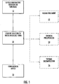
- a low-dose-rate (LDR) brachytherapy device can be formed by depositing a solution including a soluble form of a radioactive material on a substrate (Block 10).
- the soluble form of the radioactive material e.g., a water-soluble radioactive material
- a medical device can be formed from the substrate and the water-insoluble form of the radioactive material (Block 30).
- the solution deposited on the substrate at Block 10 may include solvents in addition to or in place of water, such as HCl.
- the soluble form of the radioactive material may be water-soluble or soluble in a solvent other than water without departing from the scope of the invention.
- the water-insoluble form of the radioactive material can be formed by various techniques, including plasma decomposition ( Figure 1 ; Block 22), chemical precipitation ( Figure 1 ; Block 24), thermal decomposition ( Figure 1 ; Block 26) and/or combinations thereof.
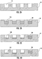
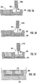
- a substrate 50 is provided with microwells 52 therein.
- the substrate 50 can be a polymer substrate such as a nylon substrate. The selection of the polymer will be within the skill of one in the art.
- a volume of radioactive salt solution 54A is deposited in the microwell 52 as shown in Figure 2B .
- the radioactive salt solution 54A can be deposited using a microsyringe, pipette or a solenoid dispensing system as described herein.
- the radioactive salt solution can be [Pd(NH 3 ) 4 ]Cl 2 dissolved in ammonium hydroxide (NH 4 OH) and/or PdCl 2 dissolved in HCl; however, other suitable solutions can be used.
- the salt solution 54A is optionally dried to provide a dried salt 54B as shown in Figure 2C .
- the salt 54B is then decomposed into a water-insoluble radioactive material 54C as shown in Figure 2D , for example, by chemical, thermal or plasma decomposition as described herein.
- palladium salt such as [Pd(NH 3 ) 4 ]Cl 2
- plasma decomposition can be performed, e.g., using a 50-150 mTorr (or greater) oxygen plasma for at least about 15-30 minutes at a power setting of 200 watts.
- PdCl 2 can be decomposed at about 675° C, and [Pd(NH 3 ) 4 ]Cl 2 can be decomposed at about 290° C.
- a radio marker RM can be included in one of the wells 52 (e.g., a gold marker) to increase visibility of the device during medical imaging.
- any suitable substrate can be used.
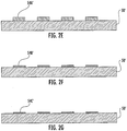
- the substrate 50' can have a generally planar or smooth surface.
- the radioactive solution 54A' can be deposited in a spaced-apart pattern on the substrate 50'.
- the radioactive solution 54A' can be evaporated as shown in Figure 2F to form a solution 54B'.
- the solution 54B' is then decomposed or converted into a water-insoluble radioactive material 54C'.
- the substrate 50, 50' and water-insoluble radioactive material 54C, 54C' of Figures 2D and 2G can be coated with a suitable biocompatible coating and formed into a medical device, such as a elongated strand or a generally planar brachytherapy device.
- a medical device such as a elongated strand or a generally planar brachytherapy device.
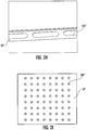
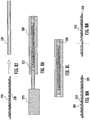
- an elongated strand substrate 50" with a water-insoluble radioactive material 54C" is shown in Figure 2H .
- An elongated substrate 50''' with a water-insoluble radioactive material 54C''' in a two dimensional, spaced-apart pattern is shown in Figure 2I .
- elongated (linear) strand substrates and planar substrates can be formed with microwells, such as the wells 52 shown in Figures 2A-2D , or on a substrate without a microwell pattern, such as a generally smooth surface as shown in Figures 2E-2G .
- the solution 54A includes Pd(NH 3 ) 4 Cl 2 , and dilute HCl (hydrochloric acid) is added to the solution 54A prior to the drying step shown in Figure 2C .
- dilute HCl hydrochloric acid
- HCl is added to Pd(NH 3 ) 4 Cl 2
- a Pd(NH 3 ) 2 Cl 2 precipitate is formed.
- a precipitant can be at least partially formed before the evaporation of the solution 54A, which can reduce uneven deposits of the salt after evaporation ( e.g ., ring patterns), which can affect the decomposition time in the plasma.
- HCl can also facilitate complete and rapid decomposition, for example, in a subsequent plasma process.
- a deposition device such as an isolated solenoid dispensing system (such as is available from Innovadyne Technologies, Inc., Santa Rosa, California (U.S.A.)) can be used to deposit a volume of Pd(NH 3 ) 4 Cl 2 ( e.g., 75 ml) into a well 52 followed by another volume ( e.g., 25 nl) of dilute HCl.
- Adding HCl may produce ammonium chloride (NH 4 Cl); however, NH 4 Cl may be decomposed in the subsequent oxygen plasma and may be removed at the end of the processing.
- the substrate 50 is treated with a plasma (such as oxygen plasma) before the radioactive salt solution 54A is deposited in Figure 2B .
- the plasma treatment may be performed at a pressure of 75-100 mTorr with a power setting of 230 Watts for 2-5 minutes, such as for about 3 minutes.
- the amount of plasma pre-treatment can be modified to provide sufficient dispersal of the salt residue within the well 52.
- plasma surface treatment can function to create surface roughening and/or "activation" of surface binding sites that favor relatively even dispersal of the salt residue within the well 52 and reduce clumping. If the plasma process is performed for an excessive amount of time, the solution 54A can spread out of the well and thus reduce containment of the palladium metal within the well 52. It should be understood that the plasma pre-treatment process described above can be performed on any suitable polymer substrate.
- a radiation detector can be used to test the radiation on the resulting medical device.
- Devices according to embodiments of the present invention can be used as low dose radiation brachytherapy devices, such as for prostate cancer, lung cancer and/or breast cancer.
- the water-insoluble form of the radioactive material is formed by exposing the substrate and the water-soluble form of the radioactive material to plasma to thereby decompose the water-soluble form of the radioactive material to a water-insoluble form.
- a hydrogen or oxygen plasma is used, typically at atmospheric pressure or in a partial vacuum.
- a polymer substrate can be used.
- the water-soluble form of the radioactive material can be a salt of Pd-103, such as tetraaminopalladium chloride.
- a 50-75 mTorr oxygen plasma was found to decompose a dried residue of tetraaminopalladium chloride in about 30 minutes at a power setting of 200 watts. Elemental analysis of the post-plasma residue confirmed that only Pd metal remained. Plasma decomposition of non-radioactive water-soluble materials are described, for example, in Korovchenko et al., Catalysis Today 102-103 (2005) 133-141 , and in U.S. Patent No. 6,383,575 .
- a brachytherapy medical device can be formed, for example, by enclosing the substrate and the water-insoluble form of the radioactive material (e.g ., the substrates 50, 50', 50" and 50''') with a biocompatible material.
- the radioactive material e.g ., the substrates 50, 50', 50" and 50'''
- a biocompatible material e.g., polymer microwells as described herein can be used to receive drops or globules of the water-soluble radioactive material in a spaced apart pattern.
- the water-soluble radioactive material can be deposited on a substantially planar substrate, e.g., in a spaced apart pattern.
- a polymer sheet can be adhered on the substrate to laminate the substrate and the water-insoluble form of the radioactive material. Elongated portions of the substrate can be cut or separated to thereby form a brachytherapy strand or a planar sheet.
- the brachytherapy strand can be positioned in a biocompatible tube, and the tube can be filled, e.g., with a curable thermoplastic resin such as epoxy, and cured such that the radioactive material is sealed. Shielding materials can be added, for example, on one side of the device, to provide reduced irradiation on a side of the device as desired using a radiation treatment plan.
- Exemplary dimensions of micropatterned wells are about 250 ⁇ m wide, around 300 ⁇ m deep, and about 650-1500 ⁇ m long. Other dimensions may be about 100-400 ⁇ m wide, around 100-500 ⁇ m deep and about 650-1500 ⁇ m long.
- the spacing between the wells can range between about 100 ⁇ m to about 250 ⁇ m.
- the radioactive material is selectively deposited (e.g., in globules) on the micropattern to provide non-uniform and/or discontinuous radiation pattern.
- suitable substrates include a suture, such as a monofilament suture, or other biodegradable or non-biodegradable material that is biocompatible and can be implanted in a patient, such as a silicon, glass or metal fiber.
- Biodegradable materials include, but are not limited to, polydioxanone, polylactide, polyglycolide, polycaprolactone, and copolymers thereof. Copolymers with trimethylene carbonate can also be used.
- Non-biodegradable materials include nylon, polyethylene terephthalate (polyester), polypropylene, expanded polytetrafluoroethylene (ePTFE), glass and metal (e.g. stainless steel), metal alloys, or the like.
- a low-dose radiation (LDR) brachytherapy device is formed by determining a radiation profile for the device based on a patient radiation treatment plan and depositing a radioactive material on the device in a pattern.
- the radioactive material can include a molecularly dispersed radioisotope.
- the pattern can include a plurality of spaced-apart, discrete globules, each globule having a respective volume of the radioactive material.
- a water soluble radioactive material in a solution is deposited on the substrate, and a water-insoluble form or precipitate of the radioactive material is formed on the substrate by plasma treatment.
- a solution having a water soluble radioactive material dispersed therein can provide a known amount of radiation because the radioactive material can be evenly dispersed in the solution. Therefore, the amount of radiation deposited on the substrate is proportional to the volume of solution deposited.
- a water soluble radioactive material can present containment and/or leakage problems in medical devices because water soluble materials may leach into the body. According to the present invention, the water soluble form of the radioactive material is converted to a water-insoluble precipitate or form by plasma treatment.
- the water-insoluble form of the radioactive material can be formed by thermal decomposition by heating the substrate, for example, at a temperature above a decomposition temperature of the radioactive material.
- the radioactive solution can include a palladium salt, and the decomposition temperature of the palladium salt can be about 290° C for Pd(NH 3 ) 2 Cl 2 .
- Certain polymer materials, such as silicon, can withstand temperatures around 290° C or higher, and therefore, can be used to form the substrate.
- the decomposition temperature of PdCl 2 is 675°C.
- a plurality of spaced-apart, hydrophilic regions are formed on a hydrophobic region of the substrate, and the solution is deposited on some of the plurality of spaced-apart, hydrophillic regions. Accordingly, the solution can adhere to the hydrophillic regions.
- the substrate is silicon and the plurality of spaced-apart, hydrophilic regions are silicon dioxide.
- a silicon substrate (optionally including a hydrophilic region of silicon dioxide) can be fixed or adhered to a polymer core.
- forming a water-insoluble precipitate or form of the radioactive material includes chemically forming the precipitate using a precipitation solution.
- the solution can be deposited in a plurality of spaced-apart wells on the substrate.
- a suitable precipitation solution can be added to the wells to chemically precipitate the radioactive material.
- the remaining solution can be removed, for example, by drying.
- the radioactive material is palladium -103 (Pd-103).
- a solution including a water-soluble form of Pd-103 can include [Pd(NH 3 ) 4 ]Cl 2 and/or PdCl 2 .
- the solution can be [Pd(NH 3 ) 4 ]Cl 2 dissolved in ammonium hydroxide (NH 4 OH) and/or PdCl 2 dissolved in HCl.
- the water-insoluble form can be formed by adding sodium borohydride (NaBH 4 ) to the [Pd(NH 3 ) 4 ]Cl 2 and/or PdCl 2 to chemically precipitate water insoluble Pd-103.
- the molar concentration of NaBH 4 can be at least twice the molar concentration of palladium ion.
- the sodium borohydride (NaBH 4 ) can be buffered in NaOH, e.g., to stabilize the sodium borohydride and/or substantially prevent the sodium borohydride from breaking down in the water solution. It is noted that sodium borohydride generally decomposes in pure water and produces hydrogen gas and sodium borate (NaBO 2 ); however, sodium hydroxide can lower the pH of the solution and reduce this decomposition of the sodium borohidride. In particular embodiments, a 20% (by weight) solution of NaOH and a 7.6% solution (by weight) of sodium borohydride can be used.
- a solution of about 2.4 % of sodium borohydride and as little as 1% NaOH can be used for a 56 mg/ml PdCl 2 solution.
- An excess of moles of sodium borohydride versus moles of palladium can be desirable so that substantially all of the palladium is precipitated (a molar ratio of at least 2, as noted above, may be sufficient).
- the ratios chosen for the precipitation solution can be selected for concentrations of palladium around 56 mg/ml or more of PdCl 2 (palladium chloride, which can be used as a precursor for either acid or base forms of the solution).
- the molar concentration of NaOH is as low as feasible so as to provide buffering against rapid hydroloysis of sodium borohydride.
- the molar concentration of NaOH can be about 0.25.
- the substrate includes aluminum and the solution can be deposited on the aluminum substrate to chemically precipitate water insoluble Pd-103.
- aluminum is added to the solution to chemically precipitate water insoluble Pd-103.
- the radioactive material comprises 1-125 and can be provided as NaI (sodium iodide).
- the water soluble solution can include NaI dissolved in NaOH.
- AgNO 3 can be added to the NaI to chemically precipitate Agl.
- Substrates according to embodiments of the present invention can be coated with a biocompatible coating, such as a polyurethane sleeve, for example, having a thickness greater than 150 micrometers.
- a biocompatible coating such as a polyurethane sleeve, for example, having a thickness greater than 150 micrometers.
- a plurality of hydrophillic regions are spaced apart by hydrophobic regions, and the water insoluble precipitate of the radioactive material is on at least some of the plurality of hydrophillic regions.
- the substrate can be formed of silicon and the plurality of spaced-apart, hydrophilic regions can be silicon dioxide, which are optionally affixed to a polymer core.
- the radioactive material can include two radioisotopes having respective decay profiles.
- the spatial pattern and the at least two different decay profiles can provide a spatiotemporal radiation profile that can be fabricated to implement a radiation therapy plan for an individual patient.
- ratio of two or more isotopes can be modified to achieve a time-varying radiation profile and can be used to increase the radiobiological effectiveness of the LDR therapy.
- different isotopes of the same element can be used.
- the output of conventional radiation therapy planning software or other suitable radiation therapy plans can be used to determine the spatial and/or temporal radiation profile for a device.
- An example of radiation therapy planning software is VariSeedTM from Varian, Inc. (Palo Alto, CA).
- the device can be fabricated using calculated amounts of radioactive material, such as a radioactive material, that can be dispersed in a spatial pattern along a length of an elongated LDR device and/or using a mixture of two or more isotopes to achieve an appropriate temporal profile.
- the radiation therapy plan and spatial and/or temporal radiation profile of the device can take into account the effects of post-implantation edema, e.g., by adding extra length to the device and/or increasing the radioactivity of the proximal and distal ends of the device that can be implanted at an outer boundary of the tumor or organ.
- the device can include a filament that can extend outside the patient after implantation.
- the filament can have sufficient tensile strength to allow a physician to pull the brachytherapy device in the proximal direction to readjust the position of the device after placement. Once final positioning is achieved, the filament can be severed close to the skin surface.
- computer program products can be used to determine a pattern of radioactive portions and non-radioactive portions of a device and/or mixture(s) of radioisotopes to create a spatial and/or temporal radiation profile when implanted in the patient and/or to control the fabrication of the brachytherapy device.
- Brachytherapy devices can be provided that include a polymeric material having a chemically distributed therapeutic isotope throughout.
- processing techniques can be used to form radioactive materials, e.g., to form polymeric fibers of the requisite dimensions for use in LDR (low-dose-rate) brachytherapy.
- radioactive materials e.g., to form polymeric fibers of the requisite dimensions for use in LDR (low-dose-rate) brachytherapy.
- Exemplary materials are discussed herein.
- any suitable radioactive material including radioactive materials or materials that can become radioactive through irradiation, can be used.
- FIG. 3 illustrates an exemplary data processing system that can be included in devices operating in accordance with some embodiments of the present invention.
- a data processing system 116 which can be used to carry out or direct operations includes a processor 100, a memory 136 and input/output circuits 146.
- the data processing system can be incorporated in a portable communication device and/or other components of a network, such as a server.
- the processor 100 communicates with the memory 136 via an address/data bus 148 and communicates with the input/output circuits 146 via an address/data bus 149.
- the input/output circuits 146 can be used to transfer information between the memory (memory and/or storage media) 136 and another component, such as a deposition controller, beam controller or irradiation device for selectively patterning a brachytherapy device with radiation or radioactive material.
- a deposition controller such as a senor controller
- beam controller or irradiation device for selectively patterning a brachytherapy device with radiation or radioactive material.
- These components can be conventional components such as those used in many conventional data processing systems, which can be configured to operate as described herein.
- the processor 100 can be commercially available or custom microprocessor, microcontroller, digital signal processor or the like.
- the memory 136 can include any memory devices and/or storage media containing the software and data used to implement the functionality circuits or modules used in accordance with embodiments of the present invention.
- the memory 136 can include, but is not limited to, the following types of devices: cache, ROM, PROM, EPROM, EEPROM, flash memory, SRAM, DRAM and magnetic disk.
- the memory 136 can be a content addressable memory (CAM).
- the memory (and/or storage media) 136 can include several categories of software and data used in the data processing system: an operating system 152; application programs 154; input/output device circuits 146; and data 156.
- the operating system 152 can be any operating system suitable for use with a data processing system, such as IBM®, OS/2®, AIX® or zOS® operating systems or Microsoft® Windows®95, Windows98, Windows2000 or WindowsXP operating systems Unix or LinuxTM.
- IBM, OS/2, AIX and zOS are trademarks of International Business Machines Corporation in the United States, other countries, or both while Linux is a trademark of Linus Torvalds in the United States, other countries, or both.
- the input/output device circuits 146 typically include software routines accessed through the operating system 152 by the application program 154 to communicate with various devices.
- the application programs 154 are illustrative of the programs that implement the various features of the circuits and modules according to some embodiments of the present invention.
- the data 156 represents the static and dynamic data used by the application programs 154, the operating system 152 the input/output device circuits 146 and other software programs that can reside in the memory 136.
- the data processing system 116 can include several modules, including a radiation treatment planning module 120, a radiation profile control module 124, and the like.
- the modules can be configured as a single module or additional modules otherwise configured to implement the operations described herein for planning a radiation treatment plan, determining a spatial and/or temporal radiation profile for a device and/or controlling the deposition of radioactive material or other materials described herein (such as a precipitation solution) on a device to form a desired radiation pattern.
- the data 156 can include radiation data 126, for example, that can be used by the radiation treatment planning module 120 and/or radiation profile control module to design and/or fabricate a brachytherapy device.
- the radiation profile control module 124 can be configured to control a deposition device 125.
- the present invention should not be construed as limited to the configurations illustrated in Figure 3 , but can be provided by other arrangements and/or divisions of functions between data processing systems.
- Figure 3 is illustrated as having various circuits and modules, one or more of these circuits or modules can be combined, or separated further, without departing from the scope of the present invention.
- a deposition device 125 is controlled by a deposition controller (e.g ., the radiation profile control module 124 via the I/O circuits 146 of Figure 3 ) to form the radioactive portions 62 of the device 60.
- the radioactive material can be deposited in a plurality of spaced-apart, discrete globules.
- Each globule of radioactive material can include a particular volume of the material so that the pattern of radioactive material provide a desired radioactive profile.
- the globules can have relatively precisely deposited volumes between 5 and 500 nanoliters or between 10 and 200 nanoliters.
- Two or more radioisotopes can be used to provide a desired decay profile, which can vary along a length of the device.
- the volume of the radioactive material can be calculated by the radiation treatment planning module 120 and/or radiation profile control module 124 of Figure 3 .
- the amount of radioactive material is generally directly related to the amount of radiation emitted. For example, twice the amount of a radioactive material will generally result in twice the amount of radiation being emitted. Accordingly, in some embodiments, precision deposition can be used to deposit desired amounts of radioactive material to achieve a particular radiation profile.
- the deposition device 125 can be a micropipette, a microsyringe pump, or other suitable extrusion and/or deposition device, such as an Ultramicrosyringe II by World Precision Instruments, LTD, Stevenage, Hertfordshire, England.
- the deposition device 100 can deposit a volume of material with an accuracy of within 10% or less of the calculated volume.
- a syringe pump can be used to aspirate a sample solution, and then a digitally controlled gas pressure system can be used to expel a controlled volume of liquid.
- a digitally controlled gas pressure system can be used to expel a controlled volume of liquid.
- an isolated solenoid dispensing system such as is available from Innovadyne Technologies, Inc., Santa Rosa, California (U.S.A.) can be used.
- Such liquid dispensing solutions typically include a dispensing path that dispenses solution via an orifice, a rapidly actuating solenoid dispensing valve and a controlled pressurized liquid or fluid source.
- a hybrid valve can connect the dispensing path alternatively to a syringe so that the solution can be drawn into the dispensing path via the orifice when the hybrid valve is connected to the syringe. After filling the dispensing path with solution, the hybrid valve connects the dispensing path to the controlled pressurized liquid source.
- the pressurized liquid source enters the dispensing path, and a corresponding volume of the solution is displaced so that it exits the dispensing orifice.
- the amount of the pressurized liquid source entering the dispensing path can be controlled by a micro-solenoid valve and a digital pressure regulator.
- non-contact devices because contact with the dispensing surface is not required to separate the liquid droplets from the device.
- Exemplary deposition devices and deposition techniques for depositing controlled volume droplets are described, for example, in U.S. Patent Publication Nos. 20070155019 , 20030170903 , 20030167822 and 20030072679 and in U.S. Patent Nos. 7,135,146 ; 6,983,636 and 6,852,291 .
- commercially available devices such as the isolated solenoid dispensing systems described above, can be configured to accept microtiter plates; such devices can be adapted to deposit a solution including the radioactive material on a substrate or a plurality of substrates positioned on a cassette as described with respect to Figures 4B-4C .
- the remaining radioactive solution can be expelled into a recycling container and the syringe tip can be cleaned in water to reduce the formation of salt crystals in or on the syringe tip to reduce or eliminate clogging.
- the volume of the solution can be about 75 nanoliters; however, the concentration of radioactive material/drop volume can be selected (e.g., 50-100 nanoliters) to provide a desired radioactivity (higher or lower around the central value).
- the radioactive material is in a salt solution, such as Pd(NH 3 ) 4 Cl 2 .
- a salt solution such as Pd(NH 3 ) 4 Cl 2 .
- One technique for controlling the concentration of the radioactive material in a volume of solution is to evaporate a solution leaving the salt residue, which is then weighed before being reconstituted into a solution using an appropriate volume of solvent (e.g ., water and ammonium hydroxide) to provide the desired radioactivity per volume.
- the ammonium hydroxide can be present at 10% or greater (e.g ., 28-30%) for a radioactive salt to dissolve.
- the solution can be concentrated to correspond to a range of clinically desired levels of radioactivity, and the volume of the solution drop can also be modified to enhance or reduce the activity in a given globule or well.
- the radioactive material can be formed using a radioactive precursor material so that it is radioactive at the time that it is deposited on the device 60 or, in some embodiments, the radioactive material can be in an inactive form during deposition and can be irradiated ( e.g ., by neutron bombardment) after it is deposited and/or cured to provide a radioactive device.
- a plurality of substrates 60 can be positioned on a cassette 66.
- the cassette 66 includes grooves, and the substrates 60 are positioned in the grooves.
- the deposition device 125 of Figure 4A can be used to deposit radioactive material or other materials such as a precipitation solution on the substrates 60.
- the deposition device 125 is a micropipette having a reservoir 125A, a plunger 125B and a micropipette needle 125C.
- the plunger 125B pushes a desired amount of material through the needle 125C and deposits globules of the material at desired positions on the substrates 60.
- Figure 4D is a schematic drawings of a cassette 66 for depositing radioactive material on the substrates.
- the substrates 60 can be positioned on the substrate cassette 66, and a biocompatible coating or tube can be positioned in grooves on the cassette 66 or on another cassette so as to be aligned with the substrates such that the substrates can be pushed or urged into a biocompatible tube.
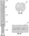
- a substrate 200 includes a plurality of microwells 202.
- a deposition device 250A such as a micropipette or micro syringe, deposits a radioactive material 204 in the form of a solution in the microwell 202.
- the solution can be tetraamine palladium chloride in ammonium hydroxide or palladium chloride in hydrochloric acid.
- the volume of the solution of radioactive material 204 can be calculated to match the desired amount of radioactivity in the well.
- a chemical precipitation solution 206 is deposited in the well on the radioactive material 204 by a deposition device 250B, such as an ink jet deposition device.
- the precipitation solution 206 can be a mixture of sodium borohydride and sodium hydroxide in sufficient amounts for a reaction to occur to precipitate out the palladium metal, which is then insoluble.
- the solution 206 and any remaining amounts of the solution containing the radioactive material 204 can be allowed to dry.
- the wells 202 are filled with a sealant 208, such as medical grade epoxy.
- the sealant 208 can then be cured, for example, by thermal or UV curing based on the type of sealant used.
- the substrate 200 can then be cleaned with a cleaning solution 212 using known techniques to remove any exposed radioactive material.
- the radioactive material 204 is in a water insoluble state and sealed by the sealant 208 to reduce or prevent leakage into the body.
- the substrate 200 can also be inserted into a sheath 214 to further reduce the risk of radiation leakage.
- a radiographic marker 216 such as a gold wire, can be affixed to the ends of the substrate 200 so that the device can be more readily imaged.
- the radiographic marker 216 can include notches 216A for allowing sealant 208 to be injected into the sheath 214 by a sealant injector 260.
- the ends of the resulting device can be trimmed ( Figure 7B ) and a plug 218, such as a polymeric plug, can be inserted on the ends of the device for further sealing and containment of the radioactive material 204.
- radiographic markers can be placed directly in the wells 202.
- a radioactive material in a solution can be converted to a water-insoluble form by thermal decomposition.
- a silicon substrate or other suitable material that can withstand the thermal processing steps can be used.
- a carrier 300 such as a glass or ceramic carrier, includes a plurality of holders 302 for holding a plurality of substrates 310.
- vacuum holes 300H can be drilled in the carrier 300 to enable immobilization of the substrates 310.
- the substrates 310 are silicon.
- the density of silicon is ⁇ 2.3 g/cc and thus is denser than polymers (which are all roughly 1 g/cc).
- the mass attenuation coefficient is roughly 5.3, and the mass attenuation coefficient for water is 0.81. Accordingly, a 100 um (about 4 mils) thick layer of silicon can lead to a 5% attenuation of the photons (whereas a 300 um layer of polymer would be about 2.5% attenuation). Small silicon chips can be even thinner than 4 mils.
- the solution can be converted to a water-insoluble form at relatively low temperatures.
- Pd(NH 3 ) 4 Cl 2 solution dries thoroughly it forms Pd(NH 3 ) 2 Cl 2 , which can be thermally decomposed at about 290°C leaving palladium metal.
- This processing temperature is consistent with certain polymers, such as silicone, and thus presents a format whereby a polymer can be used as the substrate for the conversion of Pd salt into water insoluble Pd metal.
- a deposition device 350 such as a microsyringe or micropipette, can be used to deposit a radioactive material 304 in the form of a water soluble solution on the substrates 310 ( Figures 8D-8F ).
- Silicon is hydrophobic, and therefore, the solution may bead up.
- the silicon surface is substantially free of other layers or materials. However, surface treatments and/or other material/layers can be used.
- a silicon dioxide layer is on the silicon surface in a pattern. The silicon dioxide layer is hydrophillic, and therefore can provide a surface or platform for the radioactive material solution.
- the volume of the solution can be about 50 nanoliters or about 0.46 mm in diameter; however, the concentration of radioactive material/drop volume can be selected ( e.g ., 75 nanoleters, or 50-100 nanoliters) to provide a desired radioactive activity.
- the volume of the material 304 deposited on the substrates 310 can vary, e.g., to create a variable and/or customized radiation pattern.
- the radioactive material 304 is then dried ( Figure 8F ).
- the radioactive material can be a palladium compound, such as tetraaminopalladium chloride.
- the resulting dried radioactive material 304 in Figure 8F is in a water soluble form.
- the radioactive material 304 on the carrier 300/substrate 310 is thermally decomposed at a sufficient temperature (e.g ., above about 650° C, e.g., for palladium chloride to form a water insoluble precipitate of the radioactive material.
- a sufficient temperature e.g ., above about 650° C, e.g., for palladium chloride to form a water insoluble precipitate of the radioactive material.
- a silicon compound such as palladium silicide
- a protective coating 306, such as epoxy can then be applied to the substrate 310.
- a placement device 360 such as a "pick- and-place” machine, can move the substrates 310 with the water insoluble radioactive material 340 thereon to an adhesive 322 (such as epoxy) on a polymer carrier core 320.
- the core 320 can be formed of a suitable material that can be more flexible than the substrates 310.
- the polymer core 320 can be inserted into a sheath 330 ( Figure 8J ), filled with a sealant 322 by a sealant injector 370 ( Figure 8K ), cured and/or trimmed ( Figure 8L ).
- radiographic markers 380 can also be added to the polymer core 320 ( Figure 8M ), e.g., for enhanced imaging visibility.
- a radio-opaque metal such as gold
- the polymer core 320 can be cut or sized to a desired length for implantation ( Figure 8N ).
- the core 320, sealant 322, and/or sheath 330 can be formed of a biodegradable polymer so that over time, the core 320, sealant 322, and/or sheath 330 degrades leaving the substrates 310 and radioactive material 304 implanted in the body.
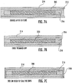
- a polymer substrate 402 is for the deposition of a plurality of spaced-apart, water-soluble solution droplets of radioactive material 404S.
- the material 404S can be deposited using various techniques described herein, such as using a syringe or micropipette.
- the water-soluble radioactive material can be a salt of Pd-103, such as tetraaminopalladium chloride or palladium chloride.
- the polymer substrate 402 can be 2 mil nylon 6,6 that is optionally coated with a thin layer of hydrophobic material, such as Epotek 302-3M (which may be thinned and spun onto the polymer substrate 402).
- the sheet could be PTFE, which is hydrophobic and gives rise to smaller dried residues.
- the water-soluble solution of radioactive material 404S is then decomposed to form a non-soluble form of the radioactive material 404NS as shown in Figure 9B .
- the polymer substrate 402 can be exposed to hydrogen or oxygen plasma to decompose the salt into palladium metal.
- a precipitation solution can be deposited on the material 402S in Figure 9A so that the water-soluble material 402S chemically precipitates to a water-insoluble form to provide the material 404NS of Figure 9B .
- a polymer sheet 406 can be adhered or laminated to the substrate 402 to form a laminated structure L as shown in Figure 9D .
- the laminated structure L can be singulated or cut or sized, for example, with a laser cutter, along cut lines C.
- the resulting laminated core 410 which includes the spaced-apart regions of the water-insoluble material 404NS.
- the laminated core 410 can be further coated or enclosed so that the water-insoluble material 404NS is sealed so as to substantially prevent leakage of the insoluble, radioactive material.
- the laminated core 410 can include a region without the material 404NS for attaching to a thread, such as a nylon thread 412.
- the thread 412 is used to position the core 410 into a tube, such as a PTFE mold tube 414 with a carbothane sleeve 416.
- the tube 414 is then filled with epoxy 418.
- the epoxy 418 is cured, and the sleeve 416 and the epoxy 418 are removed from the sleeve 416 to form a sealed device as shown in Figure 9G .
- Figures 9A-9G are described above with respect to a polymer sheet 406 that is cut, it should be understood that any suitable configuration can be used.
- the substrates 310 can be inserted into a conventional metallic brachytherapy seed structure or in a polymeric brachytherapy seed.
- implantable devices can be provided that are sized and configured to provide brachytherapy to a particular organ or region of the body.
- radioactive material can be implanted on a polymeric sheet and implanted in the patient.
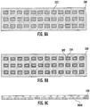
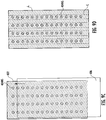
- a generally planar, 2D radioactive sheet 600 is shown.
- the sheet 600 includes a substrate 602 (which can be formed using a biodegradable or bioabsorbable material), a radiation shielding layer or gold layer 604 on the substrate 602, and a radioactive material 606 on the gold layer 602.
- the sheet 600 can optionally include perforations 608 and/or cut marks 610.
- the perforations 608 can reduce the amount of substrate material implanted in the body and/or increase fluid exchange between the two sides of the substrate 602, and the cut marks 610 can be used to allow a medical professional to cut and customize a sheet for implantation in the body.
- the gold layer 604 is shown as a continuous strip; however segmented gold areas under the radioactive material 606 can also be used. Other radioactive shielding materials can be used for the gold layer 604.
- the gold layer 604 is omitted; however, the gold layer 604 can provide radioactive shielding such that the radiation is reduced on one side of the substrate to provide substantially emissions in one direction. Reducing the radiation emitted on the side of the device adjacent the gold layer 604 and opposite the radioactive material 606 can reduce damage to health tissue in certain applications, such as lung cancer, so that the radioactive side of the sheet 600 is implanted adjacent a cancerous site.
- the substrate 602 can be imprinted with a well pattern and the gold layer 604 and radioactive material 606 can be deposited therein.
- the density and/or size of the radioactive material 606 deposited on the sheet 600 can be controlled as described herein to provide a desired radioactive profile for the sheet 600.
- a top sheet of bioabsorbable material can be laminated with bioabsorable adhesive or otherwise affixed over the radioactive material 606 to provide a generally sealed source.
- the substrate 602 can include regions that are substantially free of the radioactive material 606 to provide, for example, a border for surgical attachment. Radiomarkers such as gold squares can be added at various places on the substrate 602 to facilitate radiographic imaging and/or for dosimetry assessment after the implantation is completed.
- the gold layer 604 can be deposited on the substrate 602 by shadow masking or using appliques.
- the perforations 608 can be formed before or after the deposition of the gold layer and/or radioactive material 606.
- the radioactive material 606 can be deposited using the techniques described herein.
- a palladium (Pd) salt solution can be deposited, such as with a precision deposition system (e.g., an isolated solenoid dispensing system, such as is available from Innovadyne Technologies, Inc., Santa Rosa, California (U.S.A.)).
- the solution can be dried and/or decomposed into a water-insoluble form using the chemical, plasma and/or thermal decomposition techniques described herein.
- the gold layer 604 can be coated with an additional thin polymer layer to provide a pre-treatable surface prior to Pd solution deposition.
- the order of the radioactive layer 606 and the gold layer 604 can be reversed and/or additional substrates or coating layers may be used.
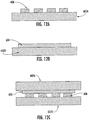
- the radioactive material 606 can be deposited on a substrate 602A as described herein.
- a gold layer 604 can be deposited on another substrate 602B.
- the two substrates 602A, 602B may be laminated together to provide substantially uni-directional radiation emissions as shown in Figure 12C such that radiation is reduced on the side of the device adjacent the substrate 602A.
- Embodiments according to the present invention will now be described with respect to exemplary lung cancer brachytherapy treatment.
- the LCSG demonstrated superior pulmonary function at 12 and 18 months post sublobar resection and brachytherapy compared to the control group treated by lobectomy alone. See R. Santos, A. Colonias, D. Parda, M. Trombetta, R. H. Maley, R. Macherey, S. Bartley, T. Santucci, R. J. Keenan, and R. J. Landreneau, "Comparison between sublobar resection and 125Iodine brachytherapy after sublobar resection in high-risk patients with Stage I non-small-cell lung cancer," Surgery, vol. 134, pp. 691-7 ; discussion 697, Oct 2003.
- Sublobar resection complimented by the intraoperative placement of a Vicryl® mesh substrate impregnated with 125 I ribbons affixed in a parallel planar array designed to deliver a dose of between 100 and 120 Gy to 0.5 cm from the perpendicular plane of the implant has been investigated. See R. Santos, A. Colonias, D. Parda, M. Trombetta, R. H. Maley, R. Macherey, S. Bartley, T. Santucci, R. J. Keenan, and R. J.
- Landreneau "Comparison between sublobar resection and 125Iodine brachytherapy after sublobar resection in high-risk patients with Stage I non-small-cell lung cancer," Surgery, vol. 134, pp. 691-7 ; discussion 697, Oct 2003; and T. A. d'Amato, M. Galloway, G. Szydlowski, A. Chen, and R. J. Landreneau, "Intraoperative brachytherapy following thoracoscopic wedge resection of stage I lung cancer," Chest, vol. 114, pp. 1112-5, Oct 1998 . Since implementation, more than 400 patients have been treated with this technique. The local failure rates have been shown to be approximately 1-3% in properly selected patients.
- the radiation is delivered in a very uniform manner with 100% patient compliance. Additionally, the delivery of radiotherapy is immediate and constant over the permanent time frame of the implant. This precludes the approximately 6-week course of external radiotherapy, decreasing time of treatment, inconvenience to the patient and overall cost.
- the morbidity associated with this procedure is low with no increase in infection or morbidity in patients treated with brachytherapy versus those treated with sublobar resection alone.
- One incidence of fatal vacular rupture developed in a patient whose dose was supplemented with external irradiation (8).
- this is now relatively contraindicated and the brachytherapy procedure is currently not performed in patients who require post-operative external irradiation. These include patients with positive mediastinal nodes proven by frozen section at the time of surgery.
- ACOSOG The American College of Surgeons Oncology Group (ACOSOG) has instituted protocol Z4032 "A randomized phase III study of sublobar resection versus sublobar resection plus brachytherapy in high risk patients with non-small cell lung cancer (NSCLC), 3 cm or smaller”. "ACOSOG protocol Z4032.”
- brachytherapy in this circumstance is a lack of a reliable and consistent delivery substrate which can be custom fitted to the individual patient.
- 125 I ribbons come pre-formed with 1.0 cm spacing between the seeds and 10 seeds per ribbon. This yields an effective treatment length of 9 cm. Many times this length is unnecessary and a shorter length would be preferred.
- there is generally a 1.0-1.5 cm spacing between each of the parallel ribbons of the 125 I implant and a substrate with a more conforming size would be preferred; if one existed.
- the technique has worked well in many patients, a significant number of implants are aborted intraoperatively as the constructed mesh would be in contact with major vascular structures (excluding the aorta) or major bronchial structures.
- a substrate which could be custom tailored and fitted intraoperatively would provide a marked improvement in the safe and limited delivery of radiation. Additionally, one in which the radiation could be effectively delivered in one direction could significantly limit the potential for unnecessary exposure to normal organs or tissues at risk. These approaches would potentially increase the numbers of patients amenable to the limited surgical approach and potentially decrease the risks associated with the procedure from an implant that was larger than necessary.
- Precision deposition of radioistope in solution can be performed as described herein on a substrate sheet that is sized and configured for implantation adjacent a patient's lung.
- the soluble isotope is converted into an insoluble form as described herein.
- Several water soluble precusor formats could be used, including tetraaminepalladium chloride: Pd(NH 3 ) 4 Cl 2 .
- Pd(NH 3 ) 4 Cl 2 tetraaminepalladium chloride
- This material can be obtained commercial with a nominal specific activity and activity per unit volume of solution. The material is first evaporated, leaving behind the palladium salt, and then reconstituted to a concentration that yields the targeted activity per unit volume needed for the desired air kerma strength of the finished device. That is, the desired precision in apparent activity is achieved by controlling the volume and activity per unit volume of a molecularly dispersed compound of the Pd-103 isotope.
- the 4-ammonia Pd salt loses two ammonia molecules to become Pd(NH 3 ) 2 Cl 2 .
- This compound will decompose, thermally, at about 290°C. See L. A. Solov'yov, A. I. Blokhin, M. L. Blokhina, I. S. Yakimov, and S. D. Kirik, "Powder diffraction study of the crystal structure of trans-Pd(NH3)2C12," Journal of Structural Chemistry, vol. 38, 1997 . Although certain polymers, like silicone, will withstand this temperature, some will not and this can be limiting in terms of a choice of materials.
- the 2-ammonia salt can also be decomposed in an oxygen plasma and this is the technique can also be used to create the subject devices.
- a planar-type reactor is used with a power level of ⁇ 200 watts.
- the oxygen pressure in the chamber is typically 100 mTorr.
- the yellowish salt of palladium visually turns black (non-water soluble Pd metal) in the plasma.
- assays of the material after treatment confirm that the salt has been decomposed (chlorine and ammonia go off as gases) and only metallic Pd remains. It is also possible to use an optical spectrometer to record the evolution of the gas species, thus creating an endpoint detection mechanism for process monitoring.
- the devices can then be trimmed to final length and are then ready for dosimetric evaluation and sterilization (e.g ., in ethylene oxide (ETO)).
- ETO ethylene oxide
- gold radiographic markers can be inserted into one or more of the nylon wells to enable visualization in clinical x-ray imaging runs (gold is not placed in wells that contain pd metal). Because of the extended length of this source, a well chamber with a long "sweet spot", the IVB-1000, is used so that the air kerma strength of the entire source can be acquired. Additionally, the source can be moved along a cylindrical aperture in the chamber to assure that the activity per unit length is within tolerance.
- a source is soaked in water (ISO 9978:1992(E)) for 4 hours at 50°C and then the soak solution is assayed.
- a scintillation fluid is added to the soak solution and then it is placed in an integrating sphere for event counting.
- the ISO metric is activity less than 5 nCi after this assay.
- Devices were evaluated according to the ANSI N43.6-2007 standards to ensure that physical damage caused by various factors would not result source leakage (specifically, the device is designated ANSI 07C22XX1X (X)).
- Biocompatibility testing Toxikon (Bedford, MA) evaluated non-radioactive analogs of finished devices. Obviously, radioactive devices would create significant tissue damage, thus masking any effects of the materials (though the devices were "aged” by administering 7 kGy of gamma radiation prior to animal testing). Tests were completed for: cytotoxicity, sensitization, irritation, and systemic toxicity and all results were negative for induced changes relative to controls. Long-term (subcutaneous) implantation tests were performed for 2, 4, 13, and 26 weeks with histopathology being performed after explantation. There were no changes recorded relative to controls. Also, an in-house image study of the explanted devices showed no apparent degradation of the polyurethane or epoxy materials. Therefore, it was concluded that the materials are safe for permanent implantation in the current device configuration.
- Monte Carlo simulation The device geometry was evaluated using the MCNP5 code. As noted above, the effective density of the unconsolidated Pd metal residue is much lower than that of the pure metal. The simulation assumed a thin layer of metal in the well with an effective density of a few percent of dense metal value. This simulation will be re-run with different dispersions of the metal to check for consistency. Because of the close placement of the wells, the source will be indistinguishable from a purely linear source. The MC predictions can be evaluated with empirical measurements, e.g., using a VAFAC electrometer.
- a linear, polymeric source can provide the following attributes:
- the flexibility of the production method can be extended to a 2-dimensional source type so as to provide a type-match for post lung resection brachytherapy.
- the deposition system described herein can be used for a flat, 2-dimensional substrate, and a desired activity per unit area can be established
- the plasma oxidation method can be used irrespective of the distribution of the Pd salt precursor (as long as the deposit size is not too large, which can extend processing time beyond acceptable limits) and irrespective of the polymer used for the substrate.
- a 2D radioactive sheet can be formed with sealed source integrity on a bioabsorbable substrate. The deposition pattern and/or shape of the device can be matched to the desired therapy plan values.
- Monte Carlo (MC) modeling will be performed using N-Particle 5 (MCNP5) transport code with updated DLC-146 photon cross sections. Where possible, specific atomic compositions of the materials will be used to ensure an accurate end result.
- the two primary goals under the modeling task are: 1) evaluate the isodose profile of the 2D sheet and 2) provide relative dose estimates (as a function of location) so as to mesh with the empirical measurements to be performed.
- the linear source aspects already investigated for the 1D source will be taken advantage of in the 2D design. Various Pd metal dot spacings will be evaluated.
- the user can physically trim the 2D source sheet in the operating room as needed based on the patient's specific anatomy after the resection is performed, which can not be feasible with current seed-based arrangements. For this to be achieved safely, cut lines will be indicated on the sheet so as to avoid slicing through the Pd metal regions themselves. The effect of such cuts will be evaluated using MC modeling as well.
- Sample devices can be made and empirical dose measurements can be conducted, for example, using non-absorbable substrates (e.g., nylon 6,6) to construct sample devices for evaluation with a lung phantom.
- Empirical dose measurements can be made at selected points in the phantom to provide quantitative validation of the Monte Carlo model predictions.
- 2D sources will be made with a nylon substrate for dosimetric tests while candidate bioabsorbable materials are evaluated in parallel.
- the techniques described herein to produce the linear sources will be applied to a 2D substrate. Specifically, the substrate will be affixed to a plastic cassette and a pattern of Pd salt dots will be applied using the microsyringe deposition system. After drying, the salt will be decomposed in oxygen plasma in situ. (For the anisotropic test device, gold dots will be pre-patterned on the substrate prior to the application of Pd material.) Previously, the endpoint (full conversion to Pd metal) was determined empirically by running the plasma process at varying times and using EDS analysis to search for salt remnants (specifically a chlorine peak).
- An optical emission spectroscopy system can be used for endpoint detection.
- This system produced by Ocean Optics (Dunedin, FL), will enable the process to be monitored over time and stopped when the decomposition products are exhausted.
- the Pd metal regions will be covered with a thin layer of medical grade epoxy to seal them. This is effectively how the 1D devices were sealed and validated.
- These materials will be input into the MC model to ensure a proper match to the empirically derived dose readings.
- gold squares of sufficient thickness to be seen with diagnostic CT will be added to the 2D source so as to enable post-implantation identification of the source location for use in clinical dosimetry (generally ⁇ 30 days after the surgery).
- Dosimetry In this task the Monte Carlo calculations will be validated in a phantom following the American Association of Physicists in Medicine Task Group Report 43 (AAPM-TG43) dosimetry protocol. Because the depth of interest in the lung brachytherapy procedure is 0.5 cm, we propose to measure the relative longitudinal dose distribution at that distance in water and lung equivalent phantom material.
- the Pd103 rectangular substrate sheet will be sandwiched between two slabs of 0.5 cm thick material that are equivalent to water in the first case and lung in the second case in terms of dose deposition from keV-range photons.
- One radiochromic film sheet will then be placed on each side of the setup, to measure the dose distribution on both sides of the Pd103 sheet.
- the radial distribution relative to the depth of 5 mm will be measured in an acrylic slab phantom (PTW type 2962, New York, NY) using a parallel plate chamber (PTW model 23342). The measurements will be made at distances of 1 to 50 mm above the center of the Pd103 sheet, in 2 mm increments. Additionally an absolute dose measurement will be made with the parallel plate chamber at a point 0.5 cm above the center of the Pd103 sheet.
- bioabsorbable materials can be evaluated for biological half-life versus sealed-source containment needs.
- Common bioabsorbable materials can be evaluated for biological half-life versus sealed-source containment needs.
- Copolymers and homopolymers of glycolic acid (GA) and L-lactic acid (LA) have generally excellent toxicological histories when used in medical implants. The focus for the current evaluation will be on copolymers using a blend of these two base materials. Vicyrl (Polyglactin 910), for instance, is formed with a 90:10 GA-to-LA blend. Another material described in the literature (17) for orthopedic uses is a mixture of 18:82 GA-to-LA blend to achieve longer-term stability in the body.
- poly-GA poly-LA 90:10 of PA LA (vicryl) Period until polymer mass becomes zero (at 37°C in saline) 60-90 days 3-5 years 70 days Period until tensile strength of polymer drops by 50% (at 37°C in saline) 14-21 days 6-12 months 21 days
- Pd-103 has a 17 day half-life and thus at 60 days, the source strength is down over 90%. For 1-125, the half-life is 60 days and thus it takes 200 days for the source strength to decay by 90%. Thus, the task of balancing radioactive half-life with bioabsorability may favor Pd-103. However, 1-125 has thus far been used exclusively for brachytherapy after sub-lobar lung resection. In terms of radiobiological differences between the isotopes, the most extensive comparative data is from use in the prostate gland (18). Despite theoretical arguments (using the linear-quadratic model) that would favor Pd-103 for more rapidly dividing cell types, there is no clear evidence of differences in outcomes. Further, the anisotropic sheet approach can allow for a net reduction of dose rate to surrounding tissues and organs.
- Accelerated Life Testing in physiologic saline at temperatures in the 45-50°C range will be undertaken. Typically this temperature range will provide a 2.5-3.5 times increase in the hydrolytic degradation of bioabsorbable polymers (19).
- the tests will investigate structural as well as sealed-source integrity.
- a non-radioactive analog of the Pd salt precursor will be used so that measurements of dissolution using HPLC (high performance liquid chromatography can be performed without the risk of contaminating equipment.
- Identically arranged test fixtures will incorporate Pd-103 so that soak samples can be taken and added to a scintillation fluid for counting purposes (to determine the extent of any radiation leakage into the soak solution).
Landscapes
- Health & Medical Sciences (AREA)
- Engineering & Computer Science (AREA)
- Biomedical Technology (AREA)
- Public Health (AREA)
- Pathology (AREA)
- Veterinary Medicine (AREA)
- General Health & Medical Sciences (AREA)
- Radiology & Medical Imaging (AREA)
- Animal Behavior & Ethology (AREA)
- Life Sciences & Earth Sciences (AREA)
- Nuclear Medicine, Radiotherapy & Molecular Imaging (AREA)
- Chemical Kinetics & Catalysis (AREA)
- General Chemical & Material Sciences (AREA)
- Chemical & Material Sciences (AREA)
- High Energy & Nuclear Physics (AREA)
- Physics & Mathematics (AREA)
- General Engineering & Computer Science (AREA)
- Radiation-Therapy Devices (AREA)
- Medicines That Contain Protein Lipid Enzymes And Other Medicines (AREA)
Claims (9)
- Procédé de formation d'un dispositif de curiethérapie à faible débit de dose (LDR), le procédé comprenant :le dépôt d'une solution comprenant une forme soluble d'un matériau radioactif (404S) sur un substrat (402) ;la conversion de la forme soluble du matériau radioactif en une forme insoluble dans l'eau (404NS) du matériau radioactif sur le substrat ; etla formation d'un dispositif médical à partir du substrat et de la forme insoluble dans l'eau du matériau radioactif ;caractérisé en ce que :
la conversion en une forme insoluble dans l'eau du matériau radioactif comprend l'exposition du substrat et de la forme soluble dans l'eau du matériau radioactif à du plasma décomposant ainsi la forme soluble du matériau radioactif en une forme insoluble dans l'eau du matériau radioactif. - Procédé selon la revendication 1, dans lequel le plasma comprend un plasma d'hydrogène et/ou un plasma d'oxygène.
- Procédé selon la revendication 1, dans lequel le substrat comprend un substrat polymère.
- Procédé selon la revendication 2, dans lequel la forme soluble du matériau radioactif comprend un sel de Pd-103.
- Procédé selon la revendication 4, dans lequel le sel de Pd-103 comprend du chlorure de tétraaminopalladium.
- Procédé selon l'une quelconque des revendications 1 à 5, dans lequel le dépôt d'une solution comprenant une forme soluble d'un matériau radioactif sur un substrat comprend le dépôt d'un réseau de globules espacés de la forme soluble du matériau radioactif sur le substrat.
- Procédé selon la revendication 6, dans lequel le substrat comprend des micro-puits et le réseau de globules espacés est déposé dans au moins une partie des micro-puits sur le substrat.
- Procédé selon la revendication 6, dans lequel le substrat est pratiquement plan.
- Procédé selon l'une quelconque des revendications précédentes, dans lequel le dépôt de la solution comprend le dépôt de globules discrets espacés de la solution à l'aide d'un système de distribution à électro-aimant comportant une source de fluide sous pression régulée, une pompe à micro-seringue et/ou une micropipette et le volume de chacun des globules est compris entre 5 et 500 nanolitres ou dans lequel le dépôt d'une solution comprenant une forme soluble d'un matériau radioactif sur un substrat comprend le dépôt de globules espacés de la forme soluble du matériau radioactif, lesdits globules ayant un volume d'environ 30 à 200 nanolitres et lesdits globules étant espacés d'environ 500 à 1000 µm.
Applications Claiming Priority (5)
| Application Number | Priority Date | Filing Date | Title |
|---|---|---|---|
| US4984308P | 2008-05-02 | 2008-05-02 | |
| US9645908P | 2008-09-12 | 2008-09-12 | |
| US15008109P | 2009-02-05 | 2009-02-05 | |
| US16636909P | 2009-04-03 | 2009-04-03 | |
| PCT/US2009/002702 WO2009134431A1 (fr) | 2008-05-02 | 2009-05-01 | Dispositifs de curiethérapie et procédés et produits de programme informatique associés |
Publications (3)
| Publication Number | Publication Date |
|---|---|
| EP2293842A1 EP2293842A1 (fr) | 2011-03-16 |
| EP2293842A4 EP2293842A4 (fr) | 2017-08-02 |
| EP2293842B1 true EP2293842B1 (fr) | 2020-08-12 |
Family
ID=41255327
Family Applications (1)
| Application Number | Title | Priority Date | Filing Date |
|---|---|---|---|
| EP09739234.4A Active EP2293842B1 (fr) | 2008-05-02 | 2009-05-01 | Dispositifs de curiethérapie et procédés |
Country Status (4)
| Country | Link |
|---|---|
| US (2) | US8323172B2 (fr) |
| EP (1) | EP2293842B1 (fr) |
| CA (1) | CA2760013C (fr) |
| WO (1) | WO2009134431A1 (fr) |
Families Citing this family (17)
| Publication number | Priority date | Publication date | Assignee | Title |
|---|---|---|---|---|
| US20110184283A1 (en) * | 2008-07-25 | 2011-07-28 | Tufts Medical Center | system and method of clinical treatment planning of complex, monte carlo-based brachytherapy dose distributions |
| WO2012061348A2 (fr) * | 2010-11-01 | 2012-05-10 | Civatech Oncology | Dispositifs de curiethérapie et procédés associés fournissant bioabsorbabilité et/ou irradiation asymétrique |
| US10350431B2 (en) | 2011-04-28 | 2019-07-16 | Gt Medical Technologies, Inc. | Customizable radioactive carriers and loading system |
| US9320517B2 (en) | 2012-01-12 | 2016-04-26 | Surgical Radiation Products, Llc | Targeting implant for external beam radiation |
| US9943706B2 (en) | 2012-01-12 | 2018-04-17 | Surgical Radiation Products, Llc | Targeting implant for external beam radiation |
| US9492683B2 (en) | 2013-03-15 | 2016-11-15 | Gammatile Llc | Dosimetrically customizable brachytherapy carriers and methods thereof in the treatment of tumors |
| US20160081763A1 (en) * | 2013-04-26 | 2016-03-24 | Georgios AREALIS | Pathology localizer and therapeutical procedure guide system |
| US9821174B1 (en) | 2015-02-06 | 2017-11-21 | Gammatile Llc | Radioactive implant planning system and placement guide system |
| CN106204170B (zh) * | 2016-09-28 | 2023-03-28 | 武汉佰合爱心文化传媒有限公司 | 一种无偿献血者礼品自动发放终端 |
| US10888710B1 (en) | 2016-11-29 | 2021-01-12 | Gt Medical Technologies, Inc. | Transparent loading apparatus |
| CN106599510B (zh) * | 2016-12-28 | 2020-01-10 | 中国科学院合肥物质科学研究院 | 一种基于网格分割的屏蔽层厚度精细配置方法 |
| AU2020201134B2 (en) * | 2018-03-07 | 2020-06-04 | Margin-Clear Pty Ltd | A topical brachytherapy device and a method of treatment of malignant cancer cells |
| KR20210008467A (ko) | 2018-03-07 | 2021-01-22 | 마진-클리어 피티와이 엘티디 | 국소 근접치료 장치 및 악성 암 세포의 치료 방법 |
| US10981018B2 (en) | 2019-02-14 | 2021-04-20 | Gt Medical Technologies, Inc. | Radioactive seed loading apparatus |
| KR20220076473A (ko) * | 2019-10-10 | 2022-06-08 | 알파 타우 메디컬 리미티드 | 방사선 치료 선원의 습식 제조 |
| CN110889848B (zh) * | 2019-12-11 | 2022-09-16 | 上海联影医疗科技股份有限公司 | 对感兴趣区域的重叠区域进行处理的系统及装置 |
| CN113599728B (zh) * | 2021-08-20 | 2022-05-17 | 北京航空航天大学 | 放疗剂量预测方法及装置 |
Family Cites Families (33)
| Publication number | Priority date | Publication date | Assignee | Title |
|---|---|---|---|---|
| US2475155A (en) * | 1945-12-27 | 1949-07-05 | Baker & Co Inc | Process of producing a supported platinum metal catalyst |
| US4510924A (en) | 1980-07-10 | 1985-04-16 | Yale-New Haven Hospital, Inc. | Brachytherapy devices and methods employing americium-241 |
| DE3404702A1 (de) | 1984-02-10 | 1985-09-05 | Degussa Ag, 6000 Frankfurt | Platin- und/oder palladium-haltige organopolysiloxan-ammoniumverbindungen, verfahren zu ihrer herstellung und verwendung |
| US5137700A (en) * | 1987-07-02 | 1992-08-11 | Nelson H. Shapiro | Processes employing iodine-iodide etching solutions |
| CA2016492A1 (fr) * | 1990-05-10 | 1991-11-10 | Farouk Tawfik Awadalla | Recuperation de metaux du groupe du platine a partir de solutions acides par reduction-precipitation a l'aide de tetrahydruroborate de sodium |
| US5378502A (en) * | 1992-09-09 | 1995-01-03 | U.S. Philips Corporation | Method of chemically modifying a surface in accordance with a pattern |
| SG48142A1 (en) * | 1993-05-05 | 1998-04-17 | Du Pont | Precision liquid addition device |
| DE19581161D2 (de) * | 1994-10-18 | 1997-07-17 | Atotech Deutschland Gmbh | Verfahren zur Abscheidung von Metallschichten |
| US6293899B1 (en) * | 1998-03-24 | 2001-09-25 | Radiomed Corporation | Transmutable radiotherapy device |
| US6143431A (en) * | 1998-05-04 | 2000-11-07 | Webster; Brian A. | Production of Palladium-103 |
| US6086942A (en) * | 1998-05-27 | 2000-07-11 | International Brachytherapy S.A. | Fluid-jet deposition of radioactive material for brachytherapy devices |
| DE19850203C1 (de) * | 1998-10-23 | 2000-05-31 | Eurotope Entwicklungsgesellsch | Radioaktive Jod-125-Seeds basierend auf Keramikträgern und Verfahren zur Herstellung dieser Seeds |
| EP1157076A1 (fr) * | 1998-11-18 | 2001-11-28 | Radiovascular Systems, L.L.C. | Solutions de revetement radioactives, procedes et substrats associes |
| JP2000180595A (ja) * | 1998-12-12 | 2000-06-30 | Eurotope Entwicklungs G Fuer Isotopentechnologien Mbh | 医療用放射性パラジウム103小型放射線源およびその製造方法 |
| US20030022383A1 (en) * | 1999-04-06 | 2003-01-30 | Uab Research Foundation | Method for screening crystallization conditions in solution crystal growth |
| ES2296622T3 (es) * | 1999-04-28 | 2008-05-01 | Medi Physics, Inc. | Productos para braquiterapia y procedimiento para su produccion. |
| US6264599B1 (en) | 1999-08-10 | 2001-07-24 | Syntheon, Llc | Radioactive therapeutic seeds having fixation structure |
| WO2001036047A1 (fr) * | 1999-11-18 | 2001-05-25 | Schrayer Howard L | Dispositif permettant d'inhiber la proliferation cellulaire |
| US6613432B2 (en) * | 1999-12-22 | 2003-09-02 | Biosurface Engineering Technologies, Inc. | Plasma-deposited coatings, devices and methods |
| US6575888B2 (en) * | 2000-01-25 | 2003-06-10 | Biosurface Engineering Technologies, Inc. | Bioabsorbable brachytherapy device |
| US6638205B1 (en) * | 2000-11-17 | 2003-10-28 | Mds (Canada) Inc. | Radioactive medical device for radiation therapy |
| US7074291B2 (en) * | 2001-11-02 | 2006-07-11 | Worldwide Medical Technologies, L.L.C. | Delivery system and method for interstitial radiation therapy using strands constructed with extruded strand housings |
| US7322928B2 (en) | 2003-03-17 | 2008-01-29 | Medi-Physics, Inc. | Products and methods for brachytherapy |
| US8540968B2 (en) * | 2004-03-02 | 2013-09-24 | Cellectar, Inc. | Phospholipid ether analogs as agents for detecting and locating cancer, and methods thereof |
| WO2005115543A1 (fr) | 2004-05-20 | 2005-12-08 | Wisconsin Alumni Research Foundation | Sources radioactives de brachytherapie a emission directionnelle |
| BRPI0419034A (pt) * | 2004-09-01 | 2007-12-11 | Eltech Systems Corp | revestimento contendo pd para sobrevoltagem de cloro inferior |
| WO2006110197A2 (fr) | 2005-03-03 | 2006-10-19 | Icon Medical Corp. | Dispositif medical en polymere biodegradable |
| US7736293B2 (en) | 2005-07-22 | 2010-06-15 | Biocompatibles Uk Limited | Implants for use in brachytherapy and other radiation therapy that resist migration and rotation |
| WO2007021776A2 (fr) | 2005-08-09 | 2007-02-22 | Board Of Regents, The University Of Texas System | Procedes et dispositifs pour la reconstruction du sein |
| ATE555737T1 (de) * | 2005-08-11 | 2012-05-15 | Navotek Medical Ltd | Lokalisation einer radioaktiven quelle |
| MX2009001265A (es) | 2006-08-07 | 2009-03-09 | Pliant Corp | Peliculas, sistemas y metodos de deteccion en caso de alteracion. |
| US7686756B2 (en) * | 2006-08-29 | 2010-03-30 | Ciratech Oncology | Brachytherapy devices and related methods and computer program products |
| CN102470184B (zh) | 2009-08-06 | 2017-05-31 | 皇家飞利浦电子股份有限公司 | 采用放射性种子的肿瘤治疗 |
-
2009
- 2009-05-01 US US12/434,131 patent/US8323172B2/en active Active
- 2009-05-01 EP EP09739234.4A patent/EP2293842B1/fr active Active
- 2009-05-01 CA CA2760013A patent/CA2760013C/fr active Active
- 2009-05-01 WO PCT/US2009/002702 patent/WO2009134431A1/fr active Application Filing
-
2012
- 2012-12-03 US US13/692,197 patent/US9180310B2/en active Active
Non-Patent Citations (1)
| Title |
|---|
| None * |
Also Published As
| Publication number | Publication date |
|---|---|
| US8323172B2 (en) | 2012-12-04 |
| US9180310B2 (en) | 2015-11-10 |
| CA2760013A1 (fr) | 2009-05-01 |
| US20130096360A1 (en) | 2013-04-18 |
| US20090275793A1 (en) | 2009-11-05 |
| EP2293842A1 (fr) | 2011-03-16 |
| EP2293842A4 (fr) | 2017-08-02 |
| CA2760013C (fr) | 2017-02-14 |
| WO2009134431A1 (fr) | 2009-11-05 |
Similar Documents
| Publication | Publication Date | Title |
|---|---|---|
| EP2293842B1 (fr) | Dispositifs de curiethérapie et procédés | |
| US6527693B2 (en) | Methods and implants for providing radiation to a patient | |
| US4706652A (en) | Temporary radiation therapy | |
| US6030333A (en) | Implantable radiotherapy device | |
| US6293899B1 (en) | Transmutable radiotherapy device | |
| AU2019247818B2 (en) | Controlled release of radionuclides | |
| EP0874665A1 (fr) | Dispositif tubulaire creux pour brachytherapie | |
| CA2409736A1 (fr) | Dispositifs de production de rayonnement et leurs procedes de fabrication | |
| US6471630B1 (en) | Transmutable radiotherapy device | |
| US11857803B2 (en) | Diffusing alpha-emitter radiation therapy with enhanced beta treatment | |
| US20080004483A1 (en) | Biodegradable seed placement device and method | |
| US6761679B2 (en) | Embedded radiation emitter for the localization and dosimetry of brachytherapy seed implants | |
| CA2413822A1 (fr) | Grains de curietherapie au palladium 103 sans porteur | |
| AU2008200015A1 (en) | Carrier-free 103ZPd brachytherapy seeds |
Legal Events
| Date | Code | Title | Description |
|---|---|---|---|
| PUAI | Public reference made under article 153(3) epc to a published international application that has entered the european phase |
Free format text: ORIGINAL CODE: 0009012 |
|
| 17P | Request for examination filed |
Effective date: 20101130 |
|
| AK | Designated contracting states |
Kind code of ref document: A1 Designated state(s): AT BE BG CH CY CZ DE DK EE ES FI FR GB GR HR HU IE IS IT LI LT LU LV MC MK MT NL NO PL PT RO SE SI SK TR |
|
| AX | Request for extension of the european patent |
Extension state: AL BA RS |
|
| DAX | Request for extension of the european patent (deleted) | ||
| REG | Reference to a national code |
Ref country code: DE Ref legal event code: R079 Ref document number: 602009062596 Country of ref document: DE Free format text: PREVIOUS MAIN CLASS: A61N0005000000 Ipc: A61N0005100000 |
|
| RA4 | Supplementary search report drawn up and despatched (corrected) |
Effective date: 20170705 |
|
| RIC1 | Information provided on ipc code assigned before grant |
Ipc: G21G 4/08 20060101ALI20170629BHEP Ipc: A61N 5/10 20060101AFI20170629BHEP |
|
| GRAP | Despatch of communication of intention to grant a patent |
Free format text: ORIGINAL CODE: EPIDOSNIGR1 |
|
| STAA | Information on the status of an ep patent application or granted ep patent |
Free format text: STATUS: GRANT OF PATENT IS INTENDED |
|
| INTG | Intention to grant announced |
Effective date: 20191210 |
|
| GRAS | Grant fee paid |
Free format text: ORIGINAL CODE: EPIDOSNIGR3 |
|
| GRAA | (expected) grant |
Free format text: ORIGINAL CODE: 0009210 |
|
| STAA | Information on the status of an ep patent application or granted ep patent |
Free format text: STATUS: THE PATENT HAS BEEN GRANTED |
|
| AK | Designated contracting states |
Kind code of ref document: B1 Designated state(s): AT BE BG CH CY CZ DE DK EE ES FI FR GB GR HR HU IE IS IT LI LT LU LV MC MK MT NL NO PL PT RO SE SI SK TR |
|
| REG | Reference to a national code |
Ref country code: GB Ref legal event code: FG4D |
|
| REG | Reference to a national code |
Ref country code: CH Ref legal event code: EP |
|
| REG | Reference to a national code |
Ref country code: IE Ref legal event code: FG4D |
|
| REG | Reference to a national code |
Ref country code: DE Ref legal event code: R096 Ref document number: 602009062596 Country of ref document: DE |
|
| REG | Reference to a national code |
Ref country code: AT Ref legal event code: REF Ref document number: 1300943 Country of ref document: AT Kind code of ref document: T Effective date: 20200915 |
|
| REG | Reference to a national code |
Ref country code: LT Ref legal event code: MG4D |
|
| REG | Reference to a national code |
Ref country code: NL Ref legal event code: MP Effective date: 20200812 |
|
| PG25 | Lapsed in a contracting state [announced via postgrant information from national office to epo] |
Ref country code: GR Free format text: LAPSE BECAUSE OF FAILURE TO SUBMIT A TRANSLATION OF THE DESCRIPTION OR TO PAY THE FEE WITHIN THE PRESCRIBED TIME-LIMIT Effective date: 20201113 Ref country code: FI Free format text: LAPSE BECAUSE OF FAILURE TO SUBMIT A TRANSLATION OF THE DESCRIPTION OR TO PAY THE FEE WITHIN THE PRESCRIBED TIME-LIMIT Effective date: 20200812 Ref country code: NO Free format text: LAPSE BECAUSE OF FAILURE TO SUBMIT A TRANSLATION OF THE DESCRIPTION OR TO PAY THE FEE WITHIN THE PRESCRIBED TIME-LIMIT Effective date: 20201112 Ref country code: HR Free format text: LAPSE BECAUSE OF FAILURE TO SUBMIT A TRANSLATION OF THE DESCRIPTION OR TO PAY THE FEE WITHIN THE PRESCRIBED TIME-LIMIT Effective date: 20200812 Ref country code: LT Free format text: LAPSE BECAUSE OF FAILURE TO SUBMIT A TRANSLATION OF THE DESCRIPTION OR TO PAY THE FEE WITHIN THE PRESCRIBED TIME-LIMIT Effective date: 20200812 Ref country code: BG Free format text: LAPSE BECAUSE OF FAILURE TO SUBMIT A TRANSLATION OF THE DESCRIPTION OR TO PAY THE FEE WITHIN THE PRESCRIBED TIME-LIMIT Effective date: 20201112 Ref country code: SE Free format text: LAPSE BECAUSE OF FAILURE TO SUBMIT A TRANSLATION OF THE DESCRIPTION OR TO PAY THE FEE WITHIN THE PRESCRIBED TIME-LIMIT Effective date: 20200812 Ref country code: ES Free format text: LAPSE BECAUSE OF FAILURE TO SUBMIT A TRANSLATION OF THE DESCRIPTION OR TO PAY THE FEE WITHIN THE PRESCRIBED TIME-LIMIT Effective date: 20200812 |
|
| REG | Reference to a national code |
Ref country code: AT Ref legal event code: MK05 Ref document number: 1300943 Country of ref document: AT Kind code of ref document: T Effective date: 20200812 |
|
| PG25 | Lapsed in a contracting state [announced via postgrant information from national office to epo] |
Ref country code: PL Free format text: LAPSE BECAUSE OF FAILURE TO SUBMIT A TRANSLATION OF THE DESCRIPTION OR TO PAY THE FEE WITHIN THE PRESCRIBED TIME-LIMIT Effective date: 20200812 Ref country code: NL Free format text: LAPSE BECAUSE OF FAILURE TO SUBMIT A TRANSLATION OF THE DESCRIPTION OR TO PAY THE FEE WITHIN THE PRESCRIBED TIME-LIMIT Effective date: 20200812 Ref country code: LV Free format text: LAPSE BECAUSE OF FAILURE TO SUBMIT A TRANSLATION OF THE DESCRIPTION OR TO PAY THE FEE WITHIN THE PRESCRIBED TIME-LIMIT Effective date: 20200812 Ref country code: IS Free format text: LAPSE BECAUSE OF FAILURE TO SUBMIT A TRANSLATION OF THE DESCRIPTION OR TO PAY THE FEE WITHIN THE PRESCRIBED TIME-LIMIT Effective date: 20201212 |
|
| PG25 | Lapsed in a contracting state [announced via postgrant information from national office to epo] |
Ref country code: DK Free format text: LAPSE BECAUSE OF FAILURE TO SUBMIT A TRANSLATION OF THE DESCRIPTION OR TO PAY THE FEE WITHIN THE PRESCRIBED TIME-LIMIT Effective date: 20200812 Ref country code: CZ Free format text: LAPSE BECAUSE OF FAILURE TO SUBMIT A TRANSLATION OF THE DESCRIPTION OR TO PAY THE FEE WITHIN THE PRESCRIBED TIME-LIMIT Effective date: 20200812 Ref country code: EE Free format text: LAPSE BECAUSE OF FAILURE TO SUBMIT A TRANSLATION OF THE DESCRIPTION OR TO PAY THE FEE WITHIN THE PRESCRIBED TIME-LIMIT Effective date: 20200812 Ref country code: RO Free format text: LAPSE BECAUSE OF FAILURE TO SUBMIT A TRANSLATION OF THE DESCRIPTION OR TO PAY THE FEE WITHIN THE PRESCRIBED TIME-LIMIT Effective date: 20200812 |
|
| REG | Reference to a national code |
Ref country code: DE Ref legal event code: R097 Ref document number: 602009062596 Country of ref document: DE |
|
| PG25 | Lapsed in a contracting state [announced via postgrant information from national office to epo] |
Ref country code: AT Free format text: LAPSE BECAUSE OF FAILURE TO SUBMIT A TRANSLATION OF THE DESCRIPTION OR TO PAY THE FEE WITHIN THE PRESCRIBED TIME-LIMIT Effective date: 20200812 |
|
| PLBE | No opposition filed within time limit |
Free format text: ORIGINAL CODE: 0009261 |
|
| STAA | Information on the status of an ep patent application or granted ep patent |
Free format text: STATUS: NO OPPOSITION FILED WITHIN TIME LIMIT |
|
| PG25 | Lapsed in a contracting state [announced via postgrant information from national office to epo] |
Ref country code: SK Free format text: LAPSE BECAUSE OF FAILURE TO SUBMIT A TRANSLATION OF THE DESCRIPTION OR TO PAY THE FEE WITHIN THE PRESCRIBED TIME-LIMIT Effective date: 20200812 |
|
| 26N | No opposition filed |
Effective date: 20210514 |
|
| PG25 | Lapsed in a contracting state [announced via postgrant information from national office to epo] |
Ref country code: IT Free format text: LAPSE BECAUSE OF FAILURE TO SUBMIT A TRANSLATION OF THE DESCRIPTION OR TO PAY THE FEE WITHIN THE PRESCRIBED TIME-LIMIT Effective date: 20200812 |
|
| PG25 | Lapsed in a contracting state [announced via postgrant information from national office to epo] |
Ref country code: SI Free format text: LAPSE BECAUSE OF FAILURE TO SUBMIT A TRANSLATION OF THE DESCRIPTION OR TO PAY THE FEE WITHIN THE PRESCRIBED TIME-LIMIT Effective date: 20200812 |
|
| REG | Reference to a national code |
Ref country code: CH Ref legal event code: PL |
|
| PG25 | Lapsed in a contracting state [announced via postgrant information from national office to epo] |
Ref country code: CH Free format text: LAPSE BECAUSE OF NON-PAYMENT OF DUE FEES Effective date: 20210531 Ref country code: MC Free format text: LAPSE BECAUSE OF FAILURE TO SUBMIT A TRANSLATION OF THE DESCRIPTION OR TO PAY THE FEE WITHIN THE PRESCRIBED TIME-LIMIT Effective date: 20200812 Ref country code: LU Free format text: LAPSE BECAUSE OF NON-PAYMENT OF DUE FEES Effective date: 20210501 Ref country code: LI Free format text: LAPSE BECAUSE OF NON-PAYMENT OF DUE FEES Effective date: 20210531 |
|
| REG | Reference to a national code |
Ref country code: BE Ref legal event code: MM Effective date: 20210531 |
|
| PG25 | Lapsed in a contracting state [announced via postgrant information from national office to epo] |
Ref country code: IE Free format text: LAPSE BECAUSE OF NON-PAYMENT OF DUE FEES Effective date: 20210501 |
|
| PG25 | Lapsed in a contracting state [announced via postgrant information from national office to epo] |
Ref country code: BE Free format text: LAPSE BECAUSE OF NON-PAYMENT OF DUE FEES Effective date: 20210531 |
|
| PG25 | Lapsed in a contracting state [announced via postgrant information from national office to epo] |
Ref country code: PT Free format text: LAPSE BECAUSE OF FAILURE TO SUBMIT A TRANSLATION OF THE DESCRIPTION OR TO PAY THE FEE WITHIN THE PRESCRIBED TIME-LIMIT Effective date: 20201214 |
|
| PGFP | Annual fee paid to national office [announced via postgrant information from national office to epo] |
Ref country code: FR Payment date: 20230328 Year of fee payment: 15 |
|
| PG25 | Lapsed in a contracting state [announced via postgrant information from national office to epo] |
Ref country code: HU Free format text: LAPSE BECAUSE OF FAILURE TO SUBMIT A TRANSLATION OF THE DESCRIPTION OR TO PAY THE FEE WITHIN THE PRESCRIBED TIME-LIMIT; INVALID AB INITIO Effective date: 20090501 Ref country code: CY Free format text: LAPSE BECAUSE OF FAILURE TO SUBMIT A TRANSLATION OF THE DESCRIPTION OR TO PAY THE FEE WITHIN THE PRESCRIBED TIME-LIMIT Effective date: 20200812 |
|
| PGFP | Annual fee paid to national office [announced via postgrant information from national office to epo] |
Ref country code: DE Payment date: 20230321 Year of fee payment: 15 |
|
| PG25 | Lapsed in a contracting state [announced via postgrant information from national office to epo] |
Ref country code: MK Free format text: LAPSE BECAUSE OF FAILURE TO SUBMIT A TRANSLATION OF THE DESCRIPTION OR TO PAY THE FEE WITHIN THE PRESCRIBED TIME-LIMIT Effective date: 20200812 |
|
| PGFP | Annual fee paid to national office [announced via postgrant information from national office to epo] |
Ref country code: GB Payment date: 20240314 Year of fee payment: 16 |