EP2293584A1 - Image information processing device, image pick-up device, image information processing method, and program - Google Patents
Image information processing device, image pick-up device, image information processing method, and program Download PDFInfo
- Publication number
- EP2293584A1 EP2293584A1 EP10767110A EP10767110A EP2293584A1 EP 2293584 A1 EP2293584 A1 EP 2293584A1 EP 10767110 A EP10767110 A EP 10767110A EP 10767110 A EP10767110 A EP 10767110A EP 2293584 A1 EP2293584 A1 EP 2293584A1
- Authority
- EP
- European Patent Office
- Prior art keywords
- depth value
- scene change
- unit
- image
- transition
- Prior art date
- Legal status (The legal status is an assumption and is not a legal conclusion. Google has not performed a legal analysis and makes no representation as to the accuracy of the status listed.)
- Withdrawn
Links
Images


Classifications
-
- H—ELECTRICITY
- H04—ELECTRIC COMMUNICATION TECHNIQUE
- H04N—PICTORIAL COMMUNICATION, e.g. TELEVISION
- H04N13/00—Stereoscopic video systems; Multi-view video systems; Details thereof
- H04N13/10—Processing, recording or transmission of stereoscopic or multi-view image signals
- H04N13/106—Processing image signals
- H04N13/122—Improving the 3D impression of stereoscopic images by modifying image signal contents, e.g. by filtering or adding monoscopic depth cues
-
- H—ELECTRICITY
- H04—ELECTRIC COMMUNICATION TECHNIQUE
- H04N—PICTORIAL COMMUNICATION, e.g. TELEVISION
- H04N13/00—Stereoscopic video systems; Multi-view video systems; Details thereof
- H04N13/10—Processing, recording or transmission of stereoscopic or multi-view image signals
- H04N13/106—Processing image signals
- H04N13/111—Transformation of image signals corresponding to virtual viewpoints, e.g. spatial image interpolation
-
- H—ELECTRICITY
- H04—ELECTRIC COMMUNICATION TECHNIQUE
- H04N—PICTORIAL COMMUNICATION, e.g. TELEVISION
- H04N13/00—Stereoscopic video systems; Multi-view video systems; Details thereof
- H04N13/10—Processing, recording or transmission of stereoscopic or multi-view image signals
- H04N13/106—Processing image signals
- H04N13/128—Adjusting depth or disparity
-
- H—ELECTRICITY
- H04—ELECTRIC COMMUNICATION TECHNIQUE
- H04N—PICTORIAL COMMUNICATION, e.g. TELEVISION
- H04N13/00—Stereoscopic video systems; Multi-view video systems; Details thereof
- H04N13/10—Processing, recording or transmission of stereoscopic or multi-view image signals
- H04N13/189—Recording image signals; Reproducing recorded image signals
-
- G—PHYSICS
- G02—OPTICS
- G02B—OPTICAL ELEMENTS, SYSTEMS OR APPARATUS
- G02B30/00—Optical systems or apparatus for producing three-dimensional [3D] effects, e.g. stereoscopic images
- G02B30/20—Optical systems or apparatus for producing three-dimensional [3D] effects, e.g. stereoscopic images by providing first and second parallax images to an observer's left and right eyes
-
- G—PHYSICS
- G02—OPTICS
- G02B—OPTICAL ELEMENTS, SYSTEMS OR APPARATUS
- G02B7/00—Mountings, adjusting means, or light-tight connections, for optical elements
- G02B7/28—Systems for automatic generation of focusing signals
- G02B7/282—Autofocusing of zoom lenses
-
- H—ELECTRICITY
- H04—ELECTRIC COMMUNICATION TECHNIQUE
- H04N—PICTORIAL COMMUNICATION, e.g. TELEVISION
- H04N13/00—Stereoscopic video systems; Multi-view video systems; Details thereof
- H04N13/30—Image reproducers
- H04N13/398—Synchronisation thereof; Control thereof
-
- H—ELECTRICITY
- H04—ELECTRIC COMMUNICATION TECHNIQUE
- H04N—PICTORIAL COMMUNICATION, e.g. TELEVISION
- H04N13/00—Stereoscopic video systems; Multi-view video systems; Details thereof
- H04N2013/0074—Stereoscopic image analysis
- H04N2013/0081—Depth or disparity estimation from stereoscopic image signals
Definitions
- the present invention relates to an image information processing apparatus, and, more specifically, relates to an image information processing apparatus that handles image information including a depth value for stereoscopic display, an image capture apparatus, a processing method for the apparatuses, and a program for causing a computer to execute the method.
- display apparatuses for displaying content display apparatuses capable of displaying not only planar (two-dimensional) content but also displaying stereoscopic (three-dimensional) content have been proposed. Because of the use of parallax (disparity) that occurs between both eyes, such display apparatuses may give an unnatural feeling to the viewer in cases such as a case where inconsistency occurs between the angle of convergence between both eyes and the focal length and a case where the value of parallax is not appropriate.
- content meta-information contains depth map information about content, and, if its maximum amount of depth is large, the value of the depth map is changed so as to be smaller than a standard value, and display is performed.
- the related art apparatus described above adjusts the amount of depth to suppress the influence on the viewer.
- display is changed based on a general relationship (the risk of so-called cybersickness) between the resistance level of the viewer and stereoscopic content, and no consideration is given to the transition of content over time.
- Stereoscopic content generally includes a scene change, and a depth value may rapidly change on the occasion of the change which may give an uncomfortable feeling to the viewer. This also becomes serious, likewise, not only in the change between stereo video images in stereoscopic content but also in the change between a stereo video image and a planar video image. Furthermore, a similar problem to that with moving images arises even in a case where a slideshow of still images is displayed.
- the present invention has been made in view of such a situation, and is intended to allow a depth value to smoothly transition during scene changes of stereoscopic content.
- the present invention has been made in order to solve the above problems, and its first aspect provides an image information processing apparatus including a scene change detection unit that detects a scene change in content, and a depth value correction unit that corrects a depth value for stereoscopic display so as to allow a change of the depth value to transition at a predetermined display speed before and after the scene change, and an image information processing method and program therefor.
- an image information processing apparatus including a scene change detection unit that detects a scene change in content, and a depth value correction unit that corrects a depth value for stereoscopic display so as to allow a change of the depth value to transition at a predetermined display speed before and after the scene change, and an image information processing method and program therefor.
- the depth value correction unit may correct a depth value corresponding to a certain area in the content so as to allow a change of the depth value to transition at a predetermined display speed before and after the scene change.
- the depth value correction unit may correct a depth value of an entire image to a telephoto side before and after the scene change.
- the depth value correction unit may correct the depth value so as to provide a transition from a depth value before the scene change to a depth value after the scene change at a predetermined display speed.
- the depth value correction unit may allow a depth value to transition in one of a predetermined period before the scene change, a predetermined period after the scene change, and a predetermined period over before and after the scene change.
- the scene change detection unit may detect, as the scene change, a change between a stereoscopic image and a planar image.
- the scene change detection unit may detect, as the scene change, a change between a moving image and a still image.
- a second aspect of the present invention provides an image information processing apparatus including a fixed depth value setting unit that sets a constant value as a fixed depth value for a depth value for providing stereoscopic display of image data forming content, a reference depth value specifying unit that selects a certain area in the image data and that specifies, as a reference depth value, a depth value corresponding to the area, and a depth value correction unit that corrects a depth value corresponding to each area of the image data using a ratio of the reference depth value to the fixed depth value, and an image information processing method and program therefor.
- a fixed depth value setting unit that sets a constant value as a fixed depth value for a depth value for providing stereoscopic display of image data forming content
- a reference depth value specifying unit that selects a certain area in the image data and that specifies, as a reference depth value, a depth value corresponding to the area
- a depth value correction unit that corrects a depth value corresponding to each area of the image data using a ratio of the
- a third aspect of the present invention provides an image capture apparatus including a captured-image supply unit that captures an image and that supplies the captured image and a depth value for stereoscopic display, a scene change detection unit that detects a scene change in the captured image, and a depth value correction unit that corrects the depth value so as to allow a change of the depth value to transition at a predetermined display speed before and after the scene change, and an image capture processing method and program therefor.
- a captured-image supply unit that captures an image and that supplies the captured image and a depth value for stereoscopic display
- a scene change detection unit that detects a scene change in the captured image
- a depth value correction unit that corrects the depth value so as to allow a change of the depth value to transition at a predetermined display speed before and after the scene change
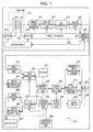
- Fig. 1 is a diagram illustrating an example overall configuration of an image capture apparatus 300 in an embodiment of the present invention.
- the image capture apparatus 300 includes a lens unit 310, motors 315 and 316 used for the operation of the lens unit 310, and a motor driver 319.
- the image capture apparatus 300 further includes an image pickup element 321, an analog processing unit 322, an A/D converter 323, a digital processing unit 324, a timing generator 325 that generates the timings thereof, and a camera control unit 329.
- the image capture apparatus 300 further includes a video encoding unit 331, a depth information setting unit 332, a file generation unit 333, a file decoding unit 334, a video decoding unit 335, and a depth information output unit 336.
- the image capture apparatus 300 further includes a memory 337, a memory controller 338 therefor, and a system control unit 339.
- a signal line from an operation receiving unit 390 is connected to the system control unit 339.
- the image capture apparatus 300 includes an error correction unit 341, a data modulation/demodulation unit 342, a magnetic field modulation driver 343, a magnetic field head 344, a servo circuit 345, a motor 346, an optical pickup 347, a drive control unit 349, and a display unit 350.
- an optical disc 370 is attached to the image capture apparatus 300.
- the lens unit 310 is configured to receive light from an object, and includes a zoom lens 311 and a focus lens 312.
- the motors 315 and 316 are connected to the zoom lens 311 and the focus lens 312, respectively, and the motors 315 and 316 are driven so that the zoom lens 311 and the focus lens 312 can be moved.
- the motor driver 319 is connected to the motors 315 and 316, and the motors 315 and 316 are controlled by the motor driver 319.
- the image pickup element 321 is an element that converts light received by the lens unit 310 into static electricity and that accumulates static electricity, and is implemented using, for example, a CCD or CMOS sensor or the like.
- the analog processing unit 322 removes noise in an analog signal from the image pickup element 321 by using correlated double sampling (CDS), and corrects the high- and low-frequency portions of the analog signal by using automatic gain control (AGC).
- CDS correlated double sampling
- A/D converter 323 converts the analog signal from the analog processing unit 322 into a digital signal.
- the digital processing unit 324 performs processing such as white balance or gamma conversion.
- the output signal from the digital processing unit 324 becomes the video signal input of the video encoding unit 331. Furthermore, the information detected by the digital processing unit 324 is transferred to the camera control unit 329.
- the camera control unit 329 performs control on the motor driver 319 and the timing generator 325 on the basis of the information detected by the digital processing unit 324.
- the timing generator 325 generates timing signals for the image pickup element 321, the analog processing unit 322, the A/D converter 323, and the digital processing unit 324. It is to be noted that the lens unit 310, the image pickup element 321, etc., which have been described, are examples of a captured-image supply unit recited in the claims.
- the video encoding unit 331 encodes a video signal.
- the depth information setting unit 332 sets depth information corresponding to the video signal.
- the file generation unit 333 generates a video file (multiplexed data) by multiplexing the encoded video signal and the depth information.
- the file decoding unit 334 decodes a video file and outputs a video signal and depth information.
- the video decoding unit 335 decodes the video signal and outputs the decoded video signal to the display unit 350.
- the depth information output unit 336 decodes the depth information and outputs the decoded depth information to the display unit 350.
- the memory 337 is a memory that holds a video file and the like.
- the memory controller 338 writes a video file (multiplexed data) supplied from the file generation unit 333 or the error correction unit 341 into the memory 337, or furthermore, reads multiplexed data from the memory 337 and supplies the multiplexed data to the error correction unit 341 or the file decoding unit 334.
- the system control unit 339 controls the operation of the memory controller 338 or the operation of the file generation unit 333 and the file decoding unit 334 as described above. Furthermore, the system control unit 339 is connected to the drive control unit 349 and makes a request for the operation of a disk drive. Furthermore, the system control unit 339 is connected to the camera control unit 329, and can obtain the autofocus and zoom state, such as whether the autofocus is in focusing action or not or the focal length.
- the operation receiving unit 390 is connected to the system control unit 339, and an operation input from the user can be recognized.
- the operation receiving unit 390 for example, buttons relating to zoom and buttons relating to recording are provided.
- the system control unit 339 is connected to the camera control unit 329, and control such as zoom is performed in accordance with an operation input from a user.
- the error correction unit 341 adds a code for interleaving and error correction to the multiplexed data from the memory controller 338, and supplies the resulting data to the data modulation/demodulation unit 342. Furthermore, the error correction unit 341 performs deinterleaving and error correction processing on a demodulated signal from the data modulation/demodulation unit 342, and supplies multiplexed data to the memory controller 338.
- the data modulation/demodulation unit 342 performs predetermined modulation for recording onto the optical disc 370, and thereafter outputs the resulting signal to the magnetic field modulation driver 343. At the same time, the data modulation/demodulation unit 342 outputs a signal for driving the optical pickup 347. Furthermore, the data modulation/demodulation unit 342 performs predetermined demodulation processing on a signal from the optical pickup 347, and outputs the resulting signal as a demodulated signal to the error correction unit 341.
- the magnetic field modulation driver 343 drives the magnetic field head 344 in accordance with an input signal, and applies a magnetic field to the optical disc 370.
- the optical pickup 347 radiates a laser beam for recording onto the optical disc 370 to record a signal onto the optical disc 370.
- the optical pickup 347 radiates a laser beam for reproduction onto the optical disc 370, performs photoelectric conversion from the amount of beam reflected from the optical disc 370 into an electrical signal, and acquires a reproduction signal.
- the above operations are performed in accordance with a request from the system control unit 339, and the drive control unit 349 issues a request to the servo circuit 345 to control the overall operation of the disk drive.
- the servo circuit 345 controls the movement servo in the disk radial direction, tracking servo, and focus servo of the optical pickup 347, and further controls the spindle servo of the motor 346.
- the optical disc 370 performs recording or reproduction of a video file (multiplexed data).
- a magneto-optical disk for magnetic field modulation is assumed.
- a similar basic configuration is used even in the case of a phase change disk.
- a magnetic disk such as a hard disk or a semiconductor disk such as an SSD (Solid State Drive) may be utilized.
- the display unit 350 is configured to display a stereoscopic image using parallax that occurs between both eyes on the basis of a video signal from the video decoding unit 335 and depth information from the depth information output unit 336.
- the scheme by which the display unit 350 performs stereoscopic display is not particularly limited, and the display unit 350 is implemented by, for example, a Micropole-type display.
- a display unit that performs stereoscopic display based on a video signal and depth information is assumed. However, this is not intended in a limiting sense. In general, it is possible to convert depth information into a left/right parallax offset value, and therefore the application to a display unit of the left/right parallax type (side-by-side type) is also possible.
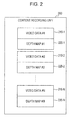
- Fig. 2 is a diagram illustrating an example configuration of a content recording unit 200 in the embodiment of the present invention.
- the content recording unit 200 is the unit of recording the video file described above.
- the content recording unit 200 holds video data items #1 to #N (210-1 to 210-N) (hereinafter also referred to as “video data items 210") and depth maps #1 to #N (220-1 to 220-N) (hereinafter also referred to simply as "depth maps 220").
- the video data items 210 and the depth maps 220 are associated with each other in units of, for example, GOPs (Groups Of Pictures). That is, the depth map 220-1 corresponds to the video data item 210-1 having the first GOP recorded therein, and the depth map 220-2 corresponds to the video data item 210-2 having the second GOP recorded therein.
- GOP is a group of frames of a moving image in MPEG (Moving Pictures Experts Group) standards. In many cases, one GOP includes 15 frames. If a frame rate of 29.97 frames/second is assumed, one GOP corresponds to approximately 0.5 seconds.
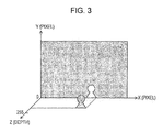
- Fig. 3 is a diagram illustrating an example of a depth map 220 in the embodiment of the present invention.
- the depth map 220 is configured to hold depth values in correspondence with individual pixels of a frame image. That is, the depth map 220 holds a depth value for each pixel on a two-dimensional XY plane.
- the depth values have values in the range of, for example, "0" to "255" using an 8-bit width, and it is assumed that the closer to the viewer a pixel is located, the larger value it has.
- depth values corresponding to a person area close to the viewer represent "255"
- depth values corresponding to a background area represent "0".
- the depth map 220 is also referred to as a depth level map.
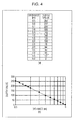
- Fig. 4 includes diagrams illustrating an example of the relationship between depth values and distances in the embodiment of the present invention. As can be seen from part (a) of Fig. 4 , if the distance from the lens to the object is less than or equal to 0.5 [m], the depth value represents "255". If the distance exceeds 5.0 [m], the depth value represents "0". In a case where the distance is greater than 0.5 [m] and less than or equal to 5.0 [m], as in part (a) of Fig. 4 , a value in the range of "0" to "255" is provided.
- the depth values are set so as to have a linear relationship with the logarithmic values of the distances. This is to take the human sense that a nearby object is more sensitively perceivable than a distant object into account.
- a depth value is set in the image capture apparatus 300
- the depth of field of the lens is controlled to be the most shallow by setting an aperture opening state at the wide end, and the focal point of the lens is set to infinity (over 5.0 [m]).
- an in-focus video area of an in-screen area is recognized, and this area is set as a background area and is assigned a depth value of "0".
- the focal point of the lens is set to a short distance (0.5 [m]) while the depth of field of the lens is controlled to be the most shallow by setting an aperture opening state at the wide end.
- an in-focus video area of an in-screen area is recognized, and this area is set as a shortest distance point and is assigned a depth value of "255".
- the focal point of the lens is sequentially changed from the short distance (0.5 [m]) to infinity (over 5.0 [m]) while the depth of field of the lens is controlled to be the most shallow by setting an aperture opening state at the wide end, and the lens position is controlled to perform distance measurement.
- in-focus video areas of in-screen areas are sequentially stored. In this way, a correspondence in part (a) of Fig. 4 is assigned.
- the depth values may be generated in real time during image capture, or may be generated afterwards from camera information.
- the camera information is obtained from inside the digital camera as information such as setting conditions at the time of photographing.
- the camera information includes information such as an F-value, an exposure time, an exposure correction value, an AGC gain value, the presence/absence of flashlight, a lens focal distance, white balance, an object distance, camera shake correction, face meta-information, digital zoom magnification, effect photographing, and a vendor name.
- This camera information can be recorded onto a modified digital video pack (MDP) as a stream file when compliant with, for example, the AVCHD standard.
- MDP modified digital video pack
- the object distance in the camera information can be utilized as a distance at this coordinate position.
- the obtained distance can be converted into a depth value from the correspondence table in part (a) of Fig. 4 .
- Fig. 5 includes diagrams illustrating the relationship between video data 210 and a depth map 220 according to an embodiment of the present invention.
- Part (a) of Fig. 5 illustrates an example of the video data 210.
- a person appears in the vicinity of the image capture apparatus, and a background appears behind the person.
- Part (b) of Fig. 5 illustrates an example of the depth map 220 corresponding to the video data 210 in part (a) of Fig. 5 .
- a depth value 221 of the area of the person represents "B4" in hexadecimal notation, that is, "180" in decimal notation. This means that the person is positioned at a distance of 1.0 [m] from the image capture apparatus.
- a depth value 222 of the background area represents "0". This means that the background is positioned at infinity (over 5.0 [m]) from the image capture apparatus.
- the depth values included in the depth map 220 correspond to the individual pixels of the video data 210.
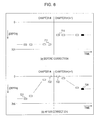
- Fig. 6 includes diagrams illustrating a first mode of depth value correction according to the embodiment of the present invention.
- a depth value 711 of a specific area in an end portion of a chapter #i changes to a depth value 714 in a start portion of a chapter #(i+1).
- a depth value of a specific area rapidly changes, which may give an unnatural feeling to the viewer.
- the specific area in this case is assumed to be an area that is a part of a frame corresponding to a person or the like, but may be the entire frame.
- the entire depth values are temporarily corrected to zero (infinity) on the occasion of a chapter change.
- a rapid change of the depth values on the occasion of a chapter change can be suppressed.
- the correction operation itself, for setting a depth value to zero is performed rapidly, the correction may bring a new unnatural feeling. Therefore, it is desirable that on the occasion of correcting a depth value, the depth value be allowed to transition at a predetermined display speed for a period of time of, for example, 0.5 seconds or more.
- an original depth value 721 in the end portion of the chapter #i is allowed to sequentially transition at a predetermined display speed so that a depth value 722 of the end frame becomes zero.
- a depth value 723 of the start frame in a chapter #(i+1) is set to zero, and is allowed to sequentially transition to an original depth value 724 in the start portion.
- Fig. 7 is a diagram illustrating an entire chapter in the first mode of depth value correction according to the embodiment of the present invention.
- a chapter #j composed of k frames is assumed.
- depth values in n frames of the start portion and in n frames of the end portion are corrected individually.
- a depth value sequentially increases from zero.
- the depth value increases from zero in steps of (1/n) and converges to a value that is not subjected to correction in the (n+1)-th frame. That is, if it is assumed that the depth value of the (n+1)-th frame is represented by A, then, the depth value of the i-th frame (i is an integer in the range of 1 to n) is given by A ⁇ ((i - 1)/n).
- a depth value sequentially decreases toward zero.
- the depth value decreases in steps of (1/n) and converges to zero in the k-th frame. That is, if it is assumed that the depth value of the (k-n)-th frame is represented by B, then, the depth value of the i-th frame (i is an integer in the range of (k-(n-1)) to k) is given by B ⁇ ((k - i)/n).
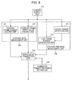
- Fig. 8 is a diagram illustrating a first example functional configuration of a depth value correction mechanism in the embodiment of the present invention.
- This depth value correction mechanism is configured to allow a depth value to smoothly transition to zero (telephoto side) before and after a scene change.
- a depth map 220 may be set after a depth value obtained on the occasion of image capture is corrected by the depth information setting unit 332, or a depth value of a depth map 220 that is not corrected may be corrected by the depth information output unit 336 and output to the display unit 350.
- the depth information setting unit 332 or the depth information output unit 336 may be provided with the depth value correction mechanism.
- this depth value correction mechanism may be implemented not only in an image capture apparatus but also in an image information processing apparatus that handles video files.
- This depth value correction mechanism includes a content supply unit 110, a content read management unit 120, a number-of-transition-frames setting unit 130, a content pre-read management unit 140, and a depth value correction unit 150.
- the content supply unit 110 is configured to supply captured content.
- content is supplied by the image pickup element 321, the camera control unit 329, or the like.
- content is supplied by a read unit (not illustrated) from a storage unit that stores the content.
- the content read management unit 120 is configured to perform management to read the content supplied from the content supply unit 110 frame-by-frame.
- the content read management unit 120 includes a current frame number holding unit 121 and a current frame depth value holding unit 122.
- the current frame number holding unit 121 is configured to hold the frame number of the current frame read from the content supply unit 110.
- the current frame depth value holding unit 122 is configured to hold the depth value corresponding to the current frame read from the content supply unit 110.
- the number-of-transition-frames setting unit 130 is configured to set in advance the number of frames to be corrected before and after a scene change.
- each group of n frames is set as the number of transition frames before and after a scene change.
- the content pre-read management unit 140 is configured to perform management to pre-read a (future) frame ahead of the current frame in the content prior to the read by the content read management unit 120.
- the content pre-read management unit 140 includes a scene change detection unit 141 and a last frame number generation unit 142.
- the scene change detection unit 141 is configured to detect the position of a scene change in the pre-read content. As the scene change, for example, a chapter change is assumed.
- the last frame number generation unit 142 is configured to generate the last frame number of the current scene on the basis of the scene change position detected by the scene change detection unit 141. In the example of Fig. 7 , the k-th frame is the last frame.
- the depth value correction unit 150 is configured to correct the depth value held in the current frame depth value holding unit 122.
- Fig. 9 is a diagram illustrating a processing flow according to the first mode of depth value correction in the embodiment of the present invention.
- scene change an example in which a chapter change is detected will be described.
- step S911 an update of the current frame is performed (step S911). That is, the current frame number held in the current frame number holding unit 121 is updated, and, in addition, the depth value held in the current frame depth value holding unit 122 is updated.
- variable m is set to "current frame number - 1" (step S914).
- the variable m is set to "last frame number - current frame number" (step S917).
- the depth value held in the current frame depth value holding unit 122 is corrected to be multiplied by "m/n" by the depth value correction unit 150 (step S918).
- a stereoscopic image is displayed on the display unit 350 on the basis of the video data and depth value of the current frame (step S919). If the current frame is in the start n frames or end n frames of the chapter, a depth value corrected in the manner described above is used, and a depth value that is not corrected is used for the other frames. It is to be noted that while, here, the operation has been described in the context of the image capture apparatus 300 including the display unit 350, a depth value may be corrected and stored on the premise of later display.
- a depth value can be allowed to smoothly transition to zero (telephoto side) before and after a scene change, and an unnatural feeling caused by a rapid change of the depth value can be overcome.
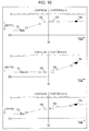
- Fig. 10 includes diagrams illustrating a second mode of depth value correction according to the embodiment of the present invention.
- a depth value is allowed to temporarily transition to zero.
- this second mode in contrast, it is assumed that a depth value is allowed to directly transition at a predetermined display speed before and after a scene change.
- Part (a) of Fig. 10 illustrates an example in which a depth value is allowed to transition only in the end portion of a chapter. That is, in this example, a depth value 731(a) is allowed to transition to a depth value 732 in the end portion of a chapter, and, in the start portion of a chapter, a constant value is maintained from a depth value 733(c) to a depth value 734.
- Part (b) of Fig. 10 illustrates an example in which a depth value is allowed to transition only in the start portion of a chapter. That is, in this example, a constant value (a) is maintained from a depth value 741 to a depth value 742 in the end portion of a chapter, and a depth value 743 is allowed to transition to a depth value 744(c) in the start portion of a chapter.
- Part (c) of Fig. 10 illustrates an example in which a depth value is allowed to transition both in the start portion and end portion of a chapter. That is, in this example, a depth value 751(a) is allowed to transition to a depth value 752 in the end portion of a chapter, and a depth value 753(b) is also allowed to transition to a depth value 754 in the start portion of a chapter.
- the transition may be performed in any period before and after a chapter change.
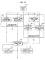
- Fig. 11 is a diagram illustrating a second example functional configuration of the depth value correction mechanism in the embodiment of the present invention.
- This depth value correction mechanism is configured to allow, in a case where a depth value rapidly changes, the change to smoothly transition.
- a depth value rapidly changes
- the scene change an example in which a chapter change is detected will be described.
- the second functional configuration of this depth value correction mechanism is similar to the first functional configuration described with reference to Fig. 8 in that a content supply unit 110, a content read management unit 120, a number-of-transition-frames setting unit 130, a content pre-read management unit 140, and a depth value correction unit 150 are provided.
- the second functional configuration of this depth value correction mechanism includes a start depth value holding unit 160 in addition to the first functional configuration.
- the content pre-read management unit 140 further includes a target depth value generation unit 143.
- the start depth value holding unit 160 is configured to hold a depth value of a start frame on the occasion of the transition of the depth value.
- the depth value 731 of the chapter #i serves as the depth value of a start frame.
- the depth value 743 of the chapter #(i+1) serves as the depth value of a start frame.
- the depth value 751 of the chapter #i and the depth value 753 of the chapter #(i+1) serve as the depth values of start frames.
- a start frame is determined based on the scene change position detected by the scene change detection unit 141 and the number of transition frames set by the number-of-transition-frames setting unit 130.
- the target depth value generation unit 143 is configured to generate a target depth value on the occasion of correcting a depth value.
- the depth value 732 of the chapter #i serves as a target depth value.
- the depth value 744 of the chapter #(i+1) serves as a target depth value.
- the depth value 752 of the chapter #i and the depth value 754 of the chapter #(i+1) serve as target depth values.
- a frame corresponding to a target depth value is determined based on the scene change position detected by the scene change detection unit 141 and the number of transition frames set by the number-of-transition-frames setting unit 130. It is to be noted that since the depth value 744 in the example of part (b) of Fig. 10 and the depth value 754 in the example of part (c) of Fig. 10 can be regarded as being substantially equivalent to the depth value of the current frame, the depth value of the current frame may be used instead. Furthermore, a target depth value can be arbitrarily determined. For example, a target depth value may be set in accordance with the dynamic range of the entirety of the next chapter.
- a depth value in the start n frames of the chapter is corrected using Equation 2 given above. Furthermore, a depth value in the end n frames of the chapter is corrected using Equation 1 given above.
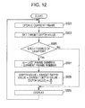
- Fig. 12 is a diagram illustrating a first processing flow according to the second mode of depth value correction in the embodiment of the present invention. This first process represents an example in a case where the transition is performed in a chapter before a change as in part (a) of Fig. 10 .
- step S921 an update of the current frame is performed (step S921). That is, the current frame number held in the current frame number holding unit 121 is updated, and, in addition, the depth value held in the current frame depth value holding unit 122 is updated. Furthermore, in the target depth value generation unit 143, a target depth value on the occasion of the transition is generated and is set (step S922).
- the target depth value in this case is the depth value 732 in part (a) of Fig. 10 .
- step S926 If the current frame is in the end n frames of the chapter (step S926), the variable m is set to "last frame number - current frame number" (step S927). Then, the depth value held in the current frame depth value holding unit 122 is corrected by the depth value correction unit 150 using Equation 1 given above (step S928).
- a stereoscopic image is displayed on the display unit 350 on the basis of the video data and depth value of the current frame (step S929). If the current frame is in the end n frames of the chapter, a depth value corrected in the manner described above is used, and a depth value that is not corrected is used for the other frames. It is to be noted that while, here, the operation has been described in the context of the image capture apparatus 300 including the display unit 350, a depth value may be corrected and stored on the premise of later display.
- Fig. 13 is a diagram illustrating a second processing flow according to the second mode of depth value correction in the embodiment of the present invention. This second process represents an example in a case where the transition is performed in a chapter after a change as in part (b) of Fig. 10 .
- step S931 an update of the current frame is performed (step S931). That is, the current frame number held in the current frame number holding unit 121 is updated, and, in addition, the depth value held in the current frame depth value holding unit 122 is updated.
- step S933 If the current frame is in the start n frames of the chapter (step S933), the variable m is set to "current frame number - 1" (step S934). Then, the depth value held in the current frame depth value holding unit 122 is corrected by the depth value correction unit 150 using Equation 2 given above (step S935).
- a stereoscopic image is displayed on the display unit 350 on the basis of the video data and depth value of the current frame (step S939). If the current frame is in the start n frames of the chapter, a depth value corrected in the manner described above is used, and a depth value that is not corrected is used for the other frames. It is to be noted that while, here, the operation has been described in the context of the image capture apparatus 300 including the display unit 350, a depth value may be corrected and stored on the premise of later display.
- Fig. 14 is a diagram illustrating a third processing flow according to the second mode of depth value correction in the embodiment of the present invention. This third process represents an example in a case where the transition is performed over chapters before and after a change as in part (c) of Fig. 10 .
- an update of the current frame is performed (step S941). That is, the current frame number held in the current frame number holding unit 121 is updated, and, in addition, the depth value held in the current frame depth value holding unit 122 is updated. Furthermore, in the target depth value generation unit 143, a target depth value on the occasion of the transition is generated and is set (step S942).
- the target depth value in this case is the depth value 752 in part (c) of Fig. 10 .
- the depth value 752 may be implemented using, for example, an average value (b) between the depth value of the end portion of the chapter #i and the depth value of the start portion of the chapter #(i+1).
- step S943 If the current frame is in the start n frames of the chapter (step S943), the variable m is set to "current frame number - 1" (step S944). Then, the depth value held in the current frame depth value holding unit 122 is corrected by the depth value correction unit 150 using Equation 2 given above (step S945).
- step S946 if the current frame is in the end n frames of the chapter (step S946), the variable m is set to "last frame number - current frame number" (step S947). Then, the depth value held in the current frame depth value holding unit 122 is corrected by the depth value correction unit 150 using Equation 1 given above (step S948).
- a stereoscopic image is displayed on the display unit 350 on the basis of the video data and depth value of the current frame (step S949). If the current frame is the start n frames or end n frames of the chapter, a depth value corrected in the manner described above is used, and a depth value that is not corrected is used for the other frames. It is to be noted that while, here, the operation has been described in the context of the image capture apparatus 300 including the display unit 350, a depth value may be corrected and stored on the premise of later display.
- a depth value can be allowed to smoothly transition before and after a scene change, and an unnatural feeling caused by a rapid change of the depth value can be overcome.
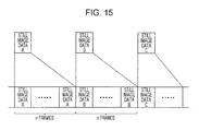
- Fig. 15 is a diagram illustrating the relationship between still image data and moving image data according to a third embodiment of the present invention.
- moving image data is generated by distributing still image data in units of n frames. That is, n frames of still image data A are arranged, thereafter, n frames of still image data B are arranged, and further n frames of still image data C are arranged. Each frame of moving image data is arranged in this manner.
- the still image data has image data and a depth value, and supports stereoscopic display.
- Even such moving image data based on still image data may involve, similarly to the case of general moving images, an unnatural feeling caused by a rapid change of a depth value.
- a depth value can possibly rapidly change on the occasion of changing of still image data.
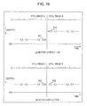
- Fig. 16 includes diagrams illustrating a third mode of depth value correction according to the embodiment of the present invention.
- a depth value 811 (d) of a specific area in an end portion of a still image A changes to a depth value 812 (e) in a start portion of a still image B.
- a depth value of a specific area rapidly changes, which may give an unnatural feeling to the viewer.
- the specific area in this case is assumed to be an area that is a part of a frame corresponding to a person or the like, but may be the entire frame.
- a depth value of a specific area of a still image is corrected so as to become a constant value (K).
- K a constant value
- Fig. 17 is a diagram illustrating a third example functional configuration of the depth value correction mechanism according to the embodiment of the present invention.
- This depth value correction mechanism is configured to maintain a depth value of a specific area at a constant value in moving image data including still image data in a slideshow format.
- a chapter change an example in which a chapter change is detected will be described.
- the third functional configuration of this depth value correction mechanism is similar to the first functional configuration described with reference to Fig. 8 in that a content supply unit 110, a content read management unit 120, and a depth value correction unit 150 are provided.
- the number-of-transition-frames setting unit 130 and the content pre-read management unit 140 are removed from the first functional configuration, and a fixed depth value setting unit 170 is further provided.
- the content read management unit 120 further includes a reference depth value specifying unit 123.
- the reference depth value specifying unit 123 is configured to specify a depth value (reference depth value) serving as a reference for a still image supplied from the content supply unit 110.
- a depth value reference depth value
- it is conceivable to extract faces in a still image select a priority face to which attention is to be paid from among the faces, and specify the depth value of the priority face as a reference depth value.
- a priority face the face that is located closest to the center or the largest face can be selected.
- the depth value positioned at the closest distance may be specified.
- the fixed depth value setting unit 170 is configured to set a constant value to be fixed as a depth value of a specific area of a still image.
- This constant value set in the fixed depth value setting unit 170 is referred to as a fixed depth value.
- the constant value K is set as a fixed depth value.
- K denotes the fixed depth value set in the fixed depth value setting unit 170
- y denotes the reference depth
- Fig. 18 is a diagram illustrating a processing flow according to the third mode of depth value correction in the embodiment of the present invention.
- scene change an example in which a chapter change is detected will be described.
- step S951 an update of the current frame is performed (step S951). That is, the depth value held in the current frame depth value holding unit 122 is updated. Furthermore, in the reference depth value specifying unit 123, a depth value is specified from the still image of the current frame (step S952).
- a priority face is detected and a reference depth value y of the priority face is specified.
- K denotes the fixed depth value set in the fixed depth value setting unit 170
- y denotes the reference depth value specified by the reference depth value specifying unit 123.
- a stereoscopic image is displayed on the display unit 350 on the basis of the video data and depth value of the current frame (step S959). It is to be noted that while, here, the operation has been described in the context of the image capture apparatus 300 including the display unit 350, a depth value may be corrected and stored on the premise of later display.
- a depth value of a specific area can be maintained at a constant value, and an unnatural feeling caused by a rapid change of the depth value can be overcome.
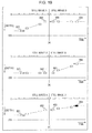
- Fig. 19 includes diagrams illustrating an exemplary modification of the third mode of depth value correction according to the embodiment of the present invention.
- a depth value is maintained at a constant value.
- a depth value is allowed to transition before and after a scene change.
- Part (a) of Fig. 19 illustrates an example in which a depth value is allowed to transition only in the end portion of a still image. That is, in this example, a depth value 831 is allowed to transition to a depth value 832 in the end portion of a still image A, and, in the start portion of a still image B, a constant value is maintained from a depth value 833 to a depth value 834.
- Part (b) of Fig. 19 illustrates an example in which a depth value is allowed to transition only in the start portion of a still image. That is, in this example, a constant value is maintained from a depth value 841 to a depth value 842 in the end portion of a still image A, and a depth value 843 is allowed to transition to a depth value 844 in the start portion of a still image B.
- Part (c) of Fig. 19 illustrates an example in which a depth value is allowed to transition both in the start portion and end portion of a still image. That is, in this example, a depth value 851 is allowed to transition to a depth value 852 in the end portion of a still image A, and a depth value 853 is also allowed to transition to a depth value 854 in the start portion of a still image B.
- the transition may be performed in any period before and after a change between still images.
- a depth value can be allowed to smoothly transition in the scene change of stereoscopic content.
- processing procedures described in the embodiments of the present invention may be regarded as a method having the above series of procedures, or may be regarded as a program for causing a computer to execute the above series of procedures or as a recording medium storing the program.
- the recording medium may be implemented using, in addition to an optical disc, a hard disk, and a semiconductor disk, for example, a CD (Compact Disc), an MD (Mini Disc), a DVD (Digital Versatile Disk), a memory card, a Blu-ray Disc (registered trademark), or the like.
- Fig. 2 video depth map values corresponding to GOPs for MPEG compression, which are recorded as video and audio streams, have been described.
- These values can be used for individual video and audio compressed streams such as, for example, a program stream of an optical disc, a TS stream used in the Blu-Ray standard or AVCHD standard, an MPEG2 stream, an H.264/AVC stream, and an MP4 stream, and future extension standards thereof.
Landscapes
- Engineering & Computer Science (AREA)
- Multimedia (AREA)
- Signal Processing (AREA)
- Testing, Inspecting, Measuring Of Stereoscopic Televisions And Televisions (AREA)
- Processing Or Creating Images (AREA)
- Image Generation (AREA)
Abstract
Description
- The present invention relates to an image information processing apparatus, and, more specifically, relates to an image information processing apparatus that handles image information including a depth value for stereoscopic display, an image capture apparatus, a processing method for the apparatuses, and a program for causing a computer to execute the method.
- In recent years, as display apparatuses for displaying content, display apparatuses capable of displaying not only planar (two-dimensional) content but also displaying stereoscopic (three-dimensional) content have been proposed. Because of the use of parallax (disparity) that occurs between both eyes, such display apparatuses may give an unnatural feeling to the viewer in cases such as a case where inconsistency occurs between the angle of convergence between both eyes and the focal length and a case where the value of parallax is not appropriate.
- Therefore, a display apparatus that calculates the degree of influence of stereoscopic content on a living body and that controls the display state of stereoscopic content to be displayed in accordance with the resistance level of the viewer has been proposed (see, for example, PTL 1). In this related art apparatus, content meta-information contains depth map information about content, and, if its maximum amount of depth is large, the value of the depth map is changed so as to be smaller than a standard value, and display is performed.
- PTL 1: Japanese Unexamined Patent Application Publication No.
2004-246725 Fig. 1 ) - The related art apparatus described above adjusts the amount of depth to suppress the influence on the viewer. In this related art apparatus, however, display is changed based on a general relationship (the risk of so-called cybersickness) between the resistance level of the viewer and stereoscopic content, and no consideration is given to the transition of content over time.
- Stereoscopic content generally includes a scene change, and a depth value may rapidly change on the occasion of the change which may give an uncomfortable feeling to the viewer. This also becomes serious, likewise, not only in the change between stereo video images in stereoscopic content but also in the change between a stereo video image and a planar video image. Furthermore, a similar problem to that with moving images arises even in a case where a slideshow of still images is displayed.
- The present invention has been made in view of such a situation, and is intended to allow a depth value to smoothly transition during scene changes of stereoscopic content.
- The present invention has been made in order to solve the above problems, and its first aspect provides an image information processing apparatus including a scene change detection unit that detects a scene change in content, and a depth value correction unit that corrects a depth value for stereoscopic display so as to allow a change of the depth value to transition at a predetermined display speed before and after the scene change, and an image information processing method and program therefor. Thus, the effect of allowing a depth value for stereoscopic display to smoothly transition before and after a scene change is provided.
- Furthermore, in this first aspect, the depth value correction unit may correct a depth value corresponding to a certain area in the content so as to allow a change of the depth value to transition at a predetermined display speed before and after the scene change. Thus, the effect of allowing a depth value corresponding to a certain area in content to smoothly transition before and after a scene change is provided.
- Furthermore, in this first aspect, the depth value correction unit may correct a depth value of an entire image to a telephoto side before and after the scene change. Thus, the effect of allowing a depth value of an entire image to a telephoto side to transition before and after a scene change is provided.
- Furthermore, in this first aspect, the depth value correction unit may correct the depth value so as to provide a transition from a depth value before the scene change to a depth value after the scene change at a predetermined display speed. Thus, the effect of allowing a smooth transition from a depth value before a scene change to a depth value after the scene change is provided.
- Furthermore, in this first aspect, the depth value correction unit may allow a depth value to transition in one of a predetermined period before the scene change, a predetermined period after the scene change, and a predetermined period over before and after the scene change.
- Furthermore, in this first aspect, the scene change detection unit may detect, as the scene change, a change between a stereoscopic image and a planar image. Thus, the effect of allowing a smooth transition before and after a change between a stereoscopic image and a planar image is provided.
- Furthermore, in this first aspect, the scene change detection unit may detect, as the scene change, a change between a moving image and a still image. Thus, the effect of allowing a smooth transition before and after a change between a moving image and a still image is provided.
- Furthermore, a second aspect of the present invention provides an image information processing apparatus including a fixed depth value setting unit that sets a constant value as a fixed depth value for a depth value for providing stereoscopic display of image data forming content, a reference depth value specifying unit that selects a certain area in the image data and that specifies, as a reference depth value, a depth value corresponding to the area, and a depth value correction unit that corrects a depth value corresponding to each area of the image data using a ratio of the reference depth value to the fixed depth value, and an image information processing method and program therefor. Thus, the effect of maintaining a depth value of a specific area at a constant value is provided.
- Furthermore, a third aspect of the present invention provides an image capture apparatus including a captured-image supply unit that captures an image and that supplies the captured image and a depth value for stereoscopic display, a scene change detection unit that detects a scene change in the captured image, and a depth value correction unit that corrects the depth value so as to allow a change of the depth value to transition at a predetermined display speed before and after the scene change, and an image capture processing method and program therefor. Thus, the effect of allowing a depth value for stereoscopic display to smoothly transition before and after a scene change is provided.
- According to the present invention, an excellent advantage of enabling a depth value to smoothly transition in a scene change of stereoscopic content is achievable. Brief Description of Drawings
-
- [
Fig. 1] Fig. 1 is a diagram illustrating an example overall configuration of animage capture apparatus 300 in an embodiment of the present invention. - [
Fig. 2] Fig. 2 is a diagram illustrating an example configuration of acontent recording unit 200 in the embodiment of the present invention. - [
Fig. 3] Fig. 3 is a diagram illustrating an example of adepth map 220 in the embodiment of the present invention. - [
Fig. 4] Fig. 4 includes diagrams illustrating an example of the relationship between depth values and distances in the embodiment of the present invention. - [
Fig. 5] Fig. 5 includes diagrams illustrating the relationship betweenvideo data 210 and adepth map 220 according to the embodiment of the present invention. - [
Fig. 6] Fig. 6 includes diagrams illustrating a first mode of depth value correction according to the embodiment of the present invention. - [
Fig. 7] Fig. 7 is a diagram illustrating an entire chapter in the first mode of depth value correction according to the embodiment of the present invention. - [
Fig. 8] Fig. 8 is a diagram illustrating a first example functional configuration of a depth value correction mechanism in the embodiment of the present invention. - [
Fig. 9] Fig. 9 is a diagram illustrating a processing flow according to the first mode of depth value correction in the embodiment of the present invention. - [
Fig. 10] Fig. 10 includes diagrams illustrating a second mode of depth value correction according to the embodiment of the present invention. - [
Fig. 11] Fig. 11 is a diagram illustrating a second example functional configuration of the depth value correction mechanism in the embodiment of the present invention. - [
Fig. 12] Fig. 12 is a diagram illustrating a first processing flow according to the second mode of depth value correction in the embodiment of the present invention. - [
Fig. 13] Fig. 13 is a diagram illustrating a second processing flow according to the second mode of depth value correction in the embodiment of the present invention. - [
Fig. 14] Fig. 14 is a diagram illustrating a third processing flow according to the second mode of depth value correction in the embodiment of the present invention. - [
Fig. 15] Fig. 15 is a diagram illustrating the relationship between still image data and moving image data in a third embodiment of the present invention. - [
Fig. 16] Fig. 16 includes diagrams illustrating a third mode of depth value correction according to the embodiment of the present invention. - [
Fig. 17] Fig. 17 is a diagram illustrating a third example functional configuration of the depth value correction mechanism in the embodiment of the present invention. - [
Fig. 18] Fig. 18 is a diagram illustrating a processing flow according to the third mode of depth value correction in the embodiment of the present invention. - [
Fig. 19] Fig. 19 includes diagrams illustrating an exemplary modification of the third mode of depth value correction according to the embodiment of the present invention. - Modes for carrying out the present invention (hereinafter referred to as embodiments) will be described hereinafter.
The description will be given in the following order: - 1. First Embodiment (an example in which a depth value is set to the telephoto side on the occasion of a scene change)
- 2. Second Embodiment (an example in which a depth value of a main image area is allowed to transition on the occasion of a scene change)
- 3. Embodiment (an example in which a depth value is corrected on the occasion of the change between slideshow still images)
- 4. Exemplary Modification
-
Fig. 1 is a diagram illustrating an example overall configuration of animage capture apparatus 300 in an embodiment of the present invention. Theimage capture apparatus 300 includes alens unit 310,motors lens unit 310, and amotor driver 319. Theimage capture apparatus 300 further includes animage pickup element 321, ananalog processing unit 322, an A/D converter 323, adigital processing unit 324, atiming generator 325 that generates the timings thereof, and acamera control unit 329. Theimage capture apparatus 300 further includes avideo encoding unit 331, a depthinformation setting unit 332, afile generation unit 333, afile decoding unit 334, avideo decoding unit 335, and a depthinformation output unit 336. Theimage capture apparatus 300 further includes amemory 337, amemory controller 338 therefor, and asystem control unit 339. A signal line from anoperation receiving unit 390 is connected to thesystem control unit 339. In addition, theimage capture apparatus 300 includes anerror correction unit 341, a data modulation/demodulation unit 342, a magneticfield modulation driver 343, amagnetic field head 344, aservo circuit 345, amotor 346, anoptical pickup 347, adrive control unit 349, and adisplay unit 350. Furthermore, as a recording medium having video recorded thereon, for example, anoptical disc 370 is attached to theimage capture apparatus 300. - The
lens unit 310 is configured to receive light from an object, and includes azoom lens 311 and afocus lens 312. Themotors zoom lens 311 and thefocus lens 312, respectively, and themotors zoom lens 311 and thefocus lens 312 can be moved. Furthermore, themotor driver 319 is connected to themotors motors motor driver 319. - The
image pickup element 321 is an element that converts light received by thelens unit 310 into static electricity and that accumulates static electricity, and is implemented using, for example, a CCD or CMOS sensor or the like. Theanalog processing unit 322 removes noise in an analog signal from theimage pickup element 321 by using correlated double sampling (CDS), and corrects the high- and low-frequency portions of the analog signal by using automatic gain control (AGC). The A/D converter 323 converts the analog signal from theanalog processing unit 322 into a digital signal. Thedigital processing unit 324 performs processing such as white balance or gamma conversion. - The output signal from the
digital processing unit 324 becomes the video signal input of thevideo encoding unit 331. Furthermore, the information detected by thedigital processing unit 324 is transferred to thecamera control unit 329. Thecamera control unit 329 performs control on themotor driver 319 and thetiming generator 325 on the basis of the information detected by thedigital processing unit 324. Thetiming generator 325 generates timing signals for theimage pickup element 321, theanalog processing unit 322, the A/D converter 323, and thedigital processing unit 324. It is to be noted that thelens unit 310, theimage pickup element 321, etc., which have been described, are examples of a captured-image supply unit recited in the claims. - The
video encoding unit 331 encodes a video signal. The depthinformation setting unit 332 sets depth information corresponding to the video signal. Thefile generation unit 333 generates a video file (multiplexed data) by multiplexing the encoded video signal and the depth information. Thefile decoding unit 334 decodes a video file and outputs a video signal and depth information. Thevideo decoding unit 335 decodes the video signal and outputs the decoded video signal to thedisplay unit 350. The depthinformation output unit 336 decodes the depth information and outputs the decoded depth information to thedisplay unit 350. - The
memory 337 is a memory that holds a video file and the like. Thememory controller 338 writes a video file (multiplexed data) supplied from thefile generation unit 333 or theerror correction unit 341 into thememory 337, or furthermore, reads multiplexed data from thememory 337 and supplies the multiplexed data to theerror correction unit 341 or thefile decoding unit 334. - The
system control unit 339 controls the operation of thememory controller 338 or the operation of thefile generation unit 333 and thefile decoding unit 334 as described above. Furthermore, thesystem control unit 339 is connected to thedrive control unit 349 and makes a request for the operation of a disk drive. Furthermore, thesystem control unit 339 is connected to thecamera control unit 329, and can obtain the autofocus and zoom state, such as whether the autofocus is in focusing action or not or the focal length. - In addition, the
operation receiving unit 390 is connected to thesystem control unit 339, and an operation input from the user can be recognized. As theoperation receiving unit 390, for example, buttons relating to zoom and buttons relating to recording are provided. Thesystem control unit 339 is connected to thecamera control unit 329, and control such as zoom is performed in accordance with an operation input from a user. - The
error correction unit 341 adds a code for interleaving and error correction to the multiplexed data from thememory controller 338, and supplies the resulting data to the data modulation/demodulation unit 342. Furthermore, theerror correction unit 341 performs deinterleaving and error correction processing on a demodulated signal from the data modulation/demodulation unit 342, and supplies multiplexed data to thememory controller 338. - The data modulation/
demodulation unit 342 performs predetermined modulation for recording onto theoptical disc 370, and thereafter outputs the resulting signal to the magneticfield modulation driver 343. At the same time, the data modulation/demodulation unit 342 outputs a signal for driving theoptical pickup 347. Furthermore, the data modulation/demodulation unit 342 performs predetermined demodulation processing on a signal from theoptical pickup 347, and outputs the resulting signal as a demodulated signal to theerror correction unit 341. - At the time of recording, the magnetic
field modulation driver 343 drives themagnetic field head 344 in accordance with an input signal, and applies a magnetic field to theoptical disc 370. At the time of recording, theoptical pickup 347 radiates a laser beam for recording onto theoptical disc 370 to record a signal onto theoptical disc 370. Furthermore, at the time of reproduction, theoptical pickup 347 radiates a laser beam for reproduction onto theoptical disc 370, performs photoelectric conversion from the amount of beam reflected from theoptical disc 370 into an electrical signal, and acquires a reproduction signal. The above operations are performed in accordance with a request from thesystem control unit 339, and thedrive control unit 349 issues a request to theservo circuit 345 to control the overall operation of the disk drive. Theservo circuit 345 controls the movement servo in the disk radial direction, tracking servo, and focus servo of theoptical pickup 347, and further controls the spindle servo of themotor 346. Thus, theoptical disc 370 performs recording or reproduction of a video file (multiplexed data). - It is to be noted that in the example configuration described above, a magneto-optical disk for magnetic field modulation is assumed. However, a similar basic configuration is used even in the case of a phase change disk. Furthermore, in place of the
optical disc 370, a magnetic disk such as a hard disk or a semiconductor disk such as an SSD (Solid State Drive) may be utilized. - The
display unit 350 is configured to display a stereoscopic image using parallax that occurs between both eyes on the basis of a video signal from thevideo decoding unit 335 and depth information from the depthinformation output unit 336. The scheme by which thedisplay unit 350 performs stereoscopic display is not particularly limited, and thedisplay unit 350 is implemented by, for example, a Micropole-type display. Furthermore, here, a display unit that performs stereoscopic display based on a video signal and depth information is assumed. However, this is not intended in a limiting sense. In general, it is possible to convert depth information into a left/right parallax offset value, and therefore the application to a display unit of the left/right parallax type (side-by-side type) is also possible. -
Fig. 2 is a diagram illustrating an example configuration of acontent recording unit 200 in the embodiment of the present invention. Thecontent recording unit 200 is the unit of recording the video file described above. Thecontent recording unit 200 holds videodata items # 1 to #N (210-1 to 210-N) (hereinafter also referred to as "video data items 210") anddepth maps # 1 to #N (220-1 to 220-N) (hereinafter also referred to simply as "depth maps 220"). - The
video data items 210 and the depth maps 220 are associated with each other in units of, for example, GOPs (Groups Of Pictures). That is, the depth map 220-1 corresponds to the video data item 210-1 having the first GOP recorded therein, and the depth map 220-2 corresponds to the video data item 210-2 having the second GOP recorded therein. GOP is a group of frames of a moving image in MPEG (Moving Pictures Experts Group) standards. In many cases, one GOP includes 15 frames. If a frame rate of 29.97 frames/second is assumed, one GOP corresponds to approximately 0.5 seconds. -
Fig. 3 is a diagram illustrating an example of adepth map 220 in the embodiment of the present invention. Thedepth map 220 is configured to hold depth values in correspondence with individual pixels of a frame image. That is, thedepth map 220 holds a depth value for each pixel on a two-dimensional XY plane. The depth values have values in the range of, for example, "0" to "255" using an 8-bit width, and it is assumed that the closer to the viewer a pixel is located, the larger value it has. In the example of this figure, depth values corresponding to a person area close to the viewer represent "255", depth values corresponding to a background area represent "0". It is to be noted that, in general, thedepth map 220 is also referred to as a depth level map. -
Fig. 4 includes diagrams illustrating an example of the relationship between depth values and distances in the embodiment of the present invention. As can be seen from part (a) ofFig. 4 , if the distance from the lens to the object is less than or equal to 0.5 [m], the depth value represents "255". If the distance exceeds 5.0 [m], the depth value represents "0". In a case where the distance is greater than 0.5 [m] and less than or equal to 5.0 [m], as in part (a) ofFig. 4 , a value in the range of "0" to "255" is provided. - Furthermore, as can be seen from part (b) of
Fig. 4 , the depth values are set so as to have a linear relationship with the logarithmic values of the distances. This is to take the human sense that a nearby object is more sensitively perceivable than a distant object into account. - In a case where a depth value is set in the
image capture apparatus 300, first, the depth of field of the lens is controlled to be the most shallow by setting an aperture opening state at the wide end, and the focal point of the lens is set to infinity (over 5.0 [m]). Thus, an in-focus video area of an in-screen area is recognized, and this area is set as a background area and is assigned a depth value of "0". Next, the focal point of the lens is set to a short distance (0.5 [m]) while the depth of field of the lens is controlled to be the most shallow by setting an aperture opening state at the wide end. Thus, an in-focus video area of an in-screen area is recognized, and this area is set as a shortest distance point and is assigned a depth value of "255". Then, the focal point of the lens is sequentially changed from the short distance (0.5 [m]) to infinity (over 5.0 [m]) while the depth of field of the lens is controlled to be the most shallow by setting an aperture opening state at the wide end, and the lens position is controlled to perform distance measurement. In synchronization with the measurement, in-focus video areas of in-screen areas are sequentially stored. In this way, a correspondence in part (a) ofFig. 4 is assigned. - After the above initial settings have been performed, it is possible to generate depth values corresponding to the individual pixels on the basis of object contour recognition or motion vector detection analysis. The depth values may be generated in real time during image capture, or may be generated afterwards from camera information. The camera information is obtained from inside the digital camera as information such as setting conditions at the time of photographing. For example, the camera information includes information such as an F-value, an exposure time, an exposure correction value, an AGC gain value, the presence/absence of flashlight, a lens focal distance, white balance, an object distance, camera shake correction, face meta-information, digital zoom magnification, effect photographing, and a vendor name. This camera information can be recorded onto a modified digital video pack (MDP) as a stream file when compliant with, for example, the AVCHD standard. In a case where the coordinates of a face that exists is known by using meta-information, the object distance in the camera information can be utilized as a distance at this coordinate position. The obtained distance can be converted into a depth value from the correspondence table in part (a) of
Fig. 4 . -
Fig. 5 includes diagrams illustrating the relationship betweenvideo data 210 and adepth map 220 according to an embodiment of the present invention. Part (a) ofFig. 5 illustrates an example of thevideo data 210. In this example, a person appears in the vicinity of the image capture apparatus, and a background appears behind the person. - Part (b) of
Fig. 5 illustrates an example of thedepth map 220 corresponding to thevideo data 210 in part (a) ofFig. 5 . Adepth value 221 of the area of the person represents "B4" in hexadecimal notation, that is, "180" in decimal notation. This means that the person is positioned at a distance of 1.0 [m] from the image capture apparatus. Adepth value 222 of the background area represents "0". This means that the background is positioned at infinity (over 5.0 [m]) from the image capture apparatus. The depth values included in thedepth map 220 correspond to the individual pixels of thevideo data 210. -
Fig. 6 includes diagrams illustrating a first mode of depth value correction according to the embodiment of the present invention. As in part (a) ofFig. 6 , a case where a depth value of an area within a frame rapidly changes on the occasion of a chapter change is assumed. Here, adepth value 711 of a specific area in an end portion of a chapter #i changes to adepth value 714 in a start portion of a chapter #(i+1). In this case, a depth value of a specific area rapidly changes, which may give an unnatural feeling to the viewer. It is to be noted that the specific area in this case is assumed to be an area that is a part of a frame corresponding to a person or the like, but may be the entire frame. - In the embodiment of the present invention, as the first mode of depth value correction, as in part (b) of
Fig. 6 , the entire depth values are temporarily corrected to zero (infinity) on the occasion of a chapter change. Thus, a rapid change of the depth values on the occasion of a chapter change can be suppressed. However, if the correction operation itself, for setting a depth value to zero, is performed rapidly, the correction may bring a new unnatural feeling. Therefore, it is desirable that on the occasion of correcting a depth value, the depth value be allowed to transition at a predetermined display speed for a period of time of, for example, 0.5 seconds or more. In the example of part (b) ofFig. 6 , anoriginal depth value 721 in the end portion of the chapter #i is allowed to sequentially transition at a predetermined display speed so that adepth value 722 of the end frame becomes zero. Similarly, adepth value 723 of the start frame in a chapter #(i+1) is set to zero, and is allowed to sequentially transition to anoriginal depth value 724 in the start portion. -
Fig. 7 is a diagram illustrating an entire chapter in the first mode of depth value correction according to the embodiment of the present invention. Here, a chapter #j composed of k frames is assumed. In the chapter #j, depth values in n frames of the start portion and in n frames of the end portion are corrected individually. - In the n frames of the start portion of the chapter #j, a depth value sequentially increases from zero. In this example, it is assumed that the depth value increases from zero in steps of (1/n) and converges to a value that is not subjected to correction in the (n+1)-th frame. That is, if it is assumed that the depth value of the (n+1)-th frame is represented by A, then, the depth value of the i-th frame (i is an integer in the range of 1 to n) is given by A × ((i - 1)/n).
- Furthermore, in the n frames of the end portion of the chapter #j, a depth value sequentially decreases toward zero. In this example, it is assumed that the depth value decreases in steps of (1/n) and converges to zero in the k-th frame. That is, if it is assumed that the depth value of the (k-n)-th frame is represented by B, then, the depth value of the i-th frame (i is an integer in the range of (k-(n-1)) to k) is given by B × ((k - i)/n).
-
Fig. 8 is a diagram illustrating a first example functional configuration of a depth value correction mechanism in the embodiment of the present invention. This depth value correction mechanism is configured to allow a depth value to smoothly transition to zero (telephoto side) before and after a scene change. In theimage capture apparatus 300, adepth map 220 may be set after a depth value obtained on the occasion of image capture is corrected by the depthinformation setting unit 332, or a depth value of adepth map 220 that is not corrected may be corrected by the depthinformation output unit 336 and output to thedisplay unit 350. In theimage capture apparatus 300, therefore, the depthinformation setting unit 332 or the depthinformation output unit 336 may be provided with the depth value correction mechanism. Furthermore, this depth value correction mechanism may be implemented not only in an image capture apparatus but also in an image information processing apparatus that handles video files. - This depth value correction mechanism includes a
content supply unit 110, a content readmanagement unit 120, a number-of-transition-frames setting unit 130, a contentpre-read management unit 140, and a depthvalue correction unit 150. - The
content supply unit 110 is configured to supply captured content. In theimage capture apparatus 300, content is supplied by theimage pickup element 321, thecamera control unit 329, or the like. In the case of an image information processing apparatus, content is supplied by a read unit (not illustrated) from a storage unit that stores the content. - The content read
management unit 120 is configured to perform management to read the content supplied from thecontent supply unit 110 frame-by-frame. The content readmanagement unit 120 includes a current framenumber holding unit 121 and a current frame depthvalue holding unit 122. The current framenumber holding unit 121 is configured to hold the frame number of the current frame read from thecontent supply unit 110. The current frame depthvalue holding unit 122 is configured to hold the depth value corresponding to the current frame read from thecontent supply unit 110. - The number-of-transition-
frames setting unit 130 is configured to set in advance the number of frames to be corrected before and after a scene change. In the example ofFig. 7 , each group of n frames is set as the number of transition frames before and after a scene change. - The content
pre-read management unit 140 is configured to perform management to pre-read a (future) frame ahead of the current frame in the content prior to the read by the content readmanagement unit 120. The contentpre-read management unit 140 includes a scenechange detection unit 141 and a last framenumber generation unit 142. The scenechange detection unit 141 is configured to detect the position of a scene change in the pre-read content. As the scene change, for example, a chapter change is assumed. The last framenumber generation unit 142 is configured to generate the last frame number of the current scene on the basis of the scene change position detected by the scenechange detection unit 141. In the example ofFig. 7 , the k-th frame is the last frame. - The depth
value correction unit 150 is configured to correct the depth value held in the current frame depthvalue holding unit 122. In the example ofFig. 7 , the depth value is corrected according to the following equation:
depth value after correction = depth value before correction × m/n
where n is the number of transition frames held in the number-of-transition-frames setting unit 130, and m is set as below in accordance with the start portion or end portion of a scene change:
In the case of the scene start n frames; m = current frame number - 1
In the case of the scene end n frames; m = last frame number - current frame number
It is to be noted that the current frame number is supplied from the current framenumber holding unit 121 and that the last frame number is supplied from the last framenumber generation unit 142. -
Fig. 9 is a diagram illustrating a processing flow according to the first mode of depth value correction in the embodiment of the present invention. Here, as an example of the scene change, an example in which a chapter change is detected will be described. - First, in the content read
management unit 120, an update of the current frame is performed (step S911). That is, the current frame number held in the current framenumber holding unit 121 is updated, and, in addition, the depth value held in the current frame depthvalue holding unit 122 is updated. - If the current frame is in the start n frames of the chapter (step S913), the variable m is set to "current frame number - 1" (step S914). On the other hand, if the current frame is in the end n frames of the chapter (step S916), the variable m is set to "last frame number - current frame number" (step S917).
- Then, if the current frame is in the start n frames or end n frames of the chapter, the depth value held in the current frame depth
value holding unit 122 is corrected to be multiplied by "m/n" by the depth value correction unit 150 (step S918). - Thereafter, a stereoscopic image is displayed on the
display unit 350 on the basis of the video data and depth value of the current frame (step S919). If the current frame is in the start n frames or end n frames of the chapter, a depth value corrected in the manner described above is used, and a depth value that is not corrected is used for the other frames. It is to be noted that while, here, the operation has been described in the context of theimage capture apparatus 300 including thedisplay unit 350, a depth value may be corrected and stored on the premise of later display. - In this manner, according to the first mode of the embodiment of the present invention, a depth value can be allowed to smoothly transition to zero (telephoto side) before and after a scene change, and an unnatural feeling caused by a rapid change of the depth value can be overcome.
-
Fig. 10 includes diagrams illustrating a second mode of depth value correction according to the embodiment of the present invention. In the first mode described above, a depth value is allowed to temporarily transition to zero. In this second mode, in contrast, it is assumed that a depth value is allowed to directly transition at a predetermined display speed before and after a scene change. - Part (a) of
Fig. 10 illustrates an example in which a depth value is allowed to transition only in the end portion of a chapter. That is, in this example, a depth value 731(a) is allowed to transition to adepth value 732 in the end portion of a chapter, and, in the start portion of a chapter, a constant value is maintained from a depth value 733(c) to adepth value 734. - Part (b) of
Fig. 10 illustrates an example in which a depth value is allowed to transition only in the start portion of a chapter. That is, in this example, a constant value (a) is maintained from adepth value 741 to adepth value 742 in the end portion of a chapter, and adepth value 743 is allowed to transition to a depth value 744(c) in the start portion of a chapter. - Part (c) of
Fig. 10 illustrates an example in which a depth value is allowed to transition both in the start portion and end portion of a chapter. That is, in this example, a depth value 751(a) is allowed to transition to adepth value 752 in the end portion of a chapter, and a depth value 753(b) is also allowed to transition to adepth value 754 in the start portion of a chapter. - In this manner, in a case where a depth value is allowed to directly transition, the transition may be performed in any period before and after a chapter change.
-
Fig. 11 is a diagram illustrating a second example functional configuration of the depth value correction mechanism in the embodiment of the present invention. This depth value correction mechanism is configured to allow, in a case where a depth value rapidly changes, the change to smoothly transition. In the following, as an example of the scene change, an example in which a chapter change is detected will be described. - The second functional configuration of this depth value correction mechanism is similar to the first functional configuration described with reference to
Fig. 8 in that acontent supply unit 110, a content readmanagement unit 120, a number-of-transition-frames setting unit 130, a contentpre-read management unit 140, and a depthvalue correction unit 150 are provided. The second functional configuration of this depth value correction mechanism includes a start depthvalue holding unit 160 in addition to the first functional configuration. Furthermore, the contentpre-read management unit 140 further includes a target depthvalue generation unit 143. - The start depth
value holding unit 160 is configured to hold a depth value of a start frame on the occasion of the transition of the depth value. In the example of part (a) ofFig. 10 , thedepth value 731 of the chapter #i serves as the depth value of a start frame. In the example of part (b) ofFig. 10 , thedepth value 743 of the chapter #(i+1) serves as the depth value of a start frame. Furthermore, in the example of part (c) ofFig. 10 , thedepth value 751 of the chapter #i and thedepth value 753 of the chapter #(i+1) serve as the depth values of start frames. A start frame is determined based on the scene change position detected by the scenechange detection unit 141 and the number of transition frames set by the number-of-transition-frames setting unit 130. - The target depth
value generation unit 143 is configured to generate a target depth value on the occasion of correcting a depth value. In the example of part (a) ofFig. 10 , thedepth value 732 of the chapter #i serves as a target depth value. In the example of part (b) ofFig. 10 , thedepth value 744 of the chapter #(i+1) serves as a target depth value. Furthermore, in the example of part (c) ofFig. 10 , thedepth value 752 of the chapter #i and thedepth value 754 of the chapter #(i+1) serve as target depth values. A frame corresponding to a target depth value is determined based on the scene change position detected by the scenechange detection unit 141 and the number of transition frames set by the number-of-transition-frames setting unit 130. It is to be noted that since thedepth value 744 in the example of part (b) ofFig. 10 and thedepth value 754 in the example of part (c) ofFig. 10 can be regarded as being substantially equivalent to the depth value of the current frame, the depth value of the current frame may be used instead. Furthermore, a target depth value can be arbitrarily determined. For example, a target depth value may be set in accordance with the dynamic range of the entirety of the next chapter. - In the second functional configuration of this depth value correction mechanism, the depth
value correction unit 150 corrects a depth value as follows. As in part (a) ofFig. 10 , in a case where the transition is performed in a chapter before a change, a depth value in the end n frames of the chapter is corrected usingEquation 1 as follows:
where
m = last frame number - current frame number. - As in part (b) of
Fig. 10 , in a case where the transition is performed in a chapter after a change, a depth value in the start n frames of the chapter is corrected usingEquation 2 as follows:
where
m = current frame number - 1. - As in part (c) of
Fig. 10 , in a case where the transition is performed over chapters before and after a change, a depth value in the start n frames of the chapter is corrected usingEquation 2 given above. Furthermore, a depth value in the end n frames of the chapter is corrected usingEquation 1 given above. -
Fig. 12 is a diagram illustrating a first processing flow according to the second mode of depth value correction in the embodiment of the present invention. This first process represents an example in a case where the transition is performed in a chapter before a change as in part (a) ofFig. 10 . - First, in the content read
management unit 120, an update of the current frame is performed (step S921). That is, the current frame number held in the current framenumber holding unit 121 is updated, and, in addition, the depth value held in the current frame depthvalue holding unit 122 is updated. Furthermore, in the target depthvalue generation unit 143, a target depth value on the occasion of the transition is generated and is set (step S922). The target depth value in this case is thedepth value 732 in part (a) ofFig. 10 . - If the current frame is in the end n frames of the chapter (step S926), the variable m is set to "last frame number - current frame number" (step S927). Then, the depth value held in the current frame depth
value holding unit 122 is corrected by the depthvalue correction unit 150 usingEquation 1 given above (step S928). - Thereafter, a stereoscopic image is displayed on the
display unit 350 on the basis of the video data and depth value of the current frame (step S929). If the current frame is in the end n frames of the chapter, a depth value corrected in the manner described above is used, and a depth value that is not corrected is used for the other frames.
It is to be noted that while, here, the operation has been described in the context of theimage capture apparatus 300 including thedisplay unit 350, a depth value may be corrected and stored on the premise of later display. -
Fig. 13 is a diagram illustrating a second processing flow according to the second mode of depth value correction in the embodiment of the present invention. This second process represents an example in a case where the transition is performed in a chapter after a change as in part (b) ofFig. 10 . - First, in the content read
management unit 120, an update of the current frame is performed (step S931). That is, the current frame number held in the current framenumber holding unit 121 is updated, and, in addition, the depth value held in the current frame depthvalue holding unit 122 is updated. - If the current frame is in the start n frames of the chapter (step S933), the variable m is set to "current frame number - 1" (step S934). Then, the depth value held in the current frame depth
value holding unit 122 is corrected by the depthvalue correction unit 150 usingEquation 2 given above (step S935). - Thereafter, a stereoscopic image is displayed on the
display unit 350 on the basis of the video data and depth value of the current frame (step S939). If the current frame is in the start n frames of the chapter, a depth value corrected in the manner described above is used, and a depth value that is not corrected is used for the other frames.
It is to be noted that while, here, the operation has been described in the context of theimage capture apparatus 300 including thedisplay unit 350, a depth value may be corrected and stored on the premise of later display. -
Fig. 14 is a diagram illustrating a third processing flow according to the second mode of depth value correction in the embodiment of the present invention. This third process represents an example in a case where the transition is performed over chapters before and after a change as in part (c) ofFig. 10 . - First, in the content read
management unit 120, an update of the current frame is performed (step S941). That is, the current frame number held in the current framenumber holding unit 121 is updated, and, in addition, the depth value held in the current frame depthvalue holding unit 122 is updated. Furthermore, in the target depthvalue generation unit 143, a target depth value on the occasion of the transition is generated and is set (step S942). The target depth value in this case is thedepth value 752 in part (c) ofFig. 10 . Thedepth value 752 may be implemented using, for example, an average value (b) between the depth value of the end portion of the chapter #i and the depth value of the start portion of the chapter #(i+1). - If the current frame is in the start n frames of the chapter (step S943), the variable m is set to "current frame number - 1" (step S944). Then, the depth value held in the current frame depth
value holding unit 122 is corrected by the depthvalue correction unit 150 usingEquation 2 given above (step S945). - On the other hand, if the current frame is in the end n frames of the chapter (step S946), the variable m is set to "last frame number - current frame number" (step S947). Then, the depth value held in the current frame depth
value holding unit 122 is corrected by the depthvalue correction unit 150 usingEquation 1 given above (step S948). - Thereafter, a stereoscopic image is displayed on the
display unit 350 on the basis of the video data and depth value of the current frame (step S949). If the current frame is the start n frames or end n frames of the chapter, a depth value corrected in the manner described above is used, and a depth value that is not corrected is used for the other frames. It is to be noted that while, here, the operation has been described in the context of theimage capture apparatus 300 including thedisplay unit 350, a depth value may be corrected and stored on the premise of later display. - In this manner, according to the second mode of the embodiment of the present invention, a depth value can be allowed to smoothly transition before and after a scene change, and an unnatural feeling caused by a rapid change of the depth value can be overcome.
-
Fig. 15 is a diagram illustrating the relationship between still image data and moving image data according to a third embodiment of the present invention. In the third embodiment, stereoscopic display of still image data in a slideshow format is assumed. Here, moving image data is generated by distributing still image data in units of n frames. That is, n frames of still image data A are arranged, thereafter, n frames of still image data B are arranged, and further n frames of still image data C are arranged. Each frame of moving image data is arranged in this manner. Similarly to frame images described with reference toFig. 3 , the still image data has image data and a depth value, and supports stereoscopic display. - Even such moving image data based on still image data may involve, similarly to the case of general moving images, an unnatural feeling caused by a rapid change of a depth value. In particular, in the case of a slideshow format, a depth value can possibly rapidly change on the occasion of changing of still image data.
-
Fig. 16 includes diagrams illustrating a third mode of depth value correction according to the embodiment of the present invention. As in part (a) ofFig. 16 , a case where a depth value of an area within a still image rapidly changes on the occasion of the change between still images is assumed. Here, a depth value 811 (d) of a specific area in an end portion of a still image A changes to a depth value 812 (e) in a start portion of a still image B. In this case, a depth value of a specific area rapidly changes, which may give an unnatural feeling to the viewer. It is to be noted that the specific area in this case is assumed to be an area that is a part of a frame corresponding to a person or the like, but may be the entire frame.
In the embodiment of the present invention, as the third mode of depth value correction, as in part (b) ofFig. 16 , a depth value of a specific area of a still image is corrected so as to become a constant value (K). Thus, a rapid change of the depth value on the occasion of a chapter change can be suppressed. -
Fig. 17 is a diagram illustrating a third example functional configuration of the depth value correction mechanism according to the embodiment of the present invention. This depth value correction mechanism is configured to maintain a depth value of a specific area at a constant value in moving image data including still image data in a slideshow format. In the following, as an example of the scene change, an example in which a chapter change is detected will be described. - The third functional configuration of this depth value correction mechanism is similar to the first functional configuration described with reference to
Fig. 8 in that acontent supply unit 110, a content readmanagement unit 120, and a depthvalue correction unit 150 are provided. In the third functional configuration of this depth value correction mechanism, the number-of-transition-frames setting unit 130 and the contentpre-read management unit 140 are removed from the first functional configuration, and a fixed depthvalue setting unit 170 is further provided. Furthermore, the content readmanagement unit 120 further includes a reference depthvalue specifying unit 123. - The reference depth
value specifying unit 123 is configured to specify a depth value (reference depth value) serving as a reference for a still image supplied from thecontent supply unit 110. In order to specify this reference depth value, it is conceivable to extract some feature value in a still image and specify a reference depth value on the basis of the feature value. For example, it is conceivable to extract faces in a still image, select a priority face to which attention is to be paid from among the faces, and specify the depth value of the priority face as a reference depth value. As a priority face, the face that is located closest to the center or the largest face can be selected. Furthermore, for example, the depth value positioned at the closest distance may be specified. - The fixed depth
value setting unit 170 is configured to set a constant value to be fixed as a depth value of a specific area of a still image. This constant value set in the fixed depthvalue setting unit 170 is referred to as a fixed depth value. In the case of the example of part (b) ofFig. 16 , the constant value K is set as a fixed depth value. - Therefore, the depth
value correction unit 150 corrects the depth value held in the current frame depthvalue holding unit 122 according to the following equation:
value setting unit 170, and y denotes the reference depth value specified by the reference depthvalue specifying unit 123. -
Fig. 18 is a diagram illustrating a processing flow according to the third mode of depth value correction in the embodiment of the present invention. Here, as an example of the scene change, an example in which a chapter change is detected will be described. - First, in the content read
management unit 120, an update of the current frame is performed (step S951). That is, the depth value held in the current frame depthvalue holding unit 122 is updated. Furthermore, in the reference depthvalue specifying unit 123, a depth value is specified from the still image of the current frame (step S952). Here, it is assumed that, as an example, a priority face is detected and a reference depth value y of the priority face is specified. - Then, the depth value held in the current frame depth
value holding unit 122 is corrected to be multiplied by "K/y" by the depth value correction unit 150 (step S958). Here, K denotes the fixed depth value set in the fixed depthvalue setting unit 170, and y denotes the reference depth value specified by the reference depthvalue specifying unit 123. - Thereafter, a stereoscopic image is displayed on the
display unit 350 on the basis of the video data and depth value of the current frame (step S959). It is to be noted that while, here, the operation has been described in the context of theimage capture apparatus 300 including thedisplay unit 350, a depth value may be corrected and stored on the premise of later display. - In this manner, according to the third mode of the embodiment of the present invention, in moving image data including still image data in a slideshow format, a depth value of a specific area can be maintained at a constant value, and an unnatural feeling caused by a rapid change of the depth value can be overcome.
-
Fig. 19 includes diagrams illustrating an exemplary modification of the third mode of depth value correction according to the embodiment of the present invention. In the third mode described above, a depth value is maintained at a constant value. In this exemplary modification, however, similarly to the second mode, it is assumed that a depth value is allowed to transition before and after a scene change. - Part (a) of
Fig. 19 illustrates an example in which a depth value is allowed to transition only in the end portion of a still image. That is, in this example, adepth value 831 is allowed to transition to adepth value 832 in the end portion of a still image A, and, in the start portion of a still image B, a constant value is maintained from adepth value 833 to adepth value 834. - Part (b) of
Fig. 19 illustrates an example in which a depth value is allowed to transition only in the start portion of a still image. That is, in this example, a constant value is maintained from adepth value 841 to adepth value 842 in the end portion of a still image A, and adepth value 843 is allowed to transition to adepth value 844 in the start portion of a still image B. - Part (c) of
Fig. 19 illustrates an example in which a depth value is allowed to transition both in the start portion and end portion of a still image. That is, in this example, adepth value 851 is allowed to transition to adepth value 852 in the end portion of a still image A, and adepth value 853 is also allowed to transition to adepth value 854 in the start portion of a still image B. - In this manner, in a case in which a depth value is allowed to transition, the transition may be performed in any period before and after a change between still images.
- In order to implement such a transition of a depth value, the functional configuration described with reference to
Fig. 11 and the processes described with reference toFigs. 12 to 14 can be utilized. That is, moving image data in a slideshow format has frames each composed of still image data, but is not different from general moving image data when viewed as a whole. Therefore, the second embodiment of the present invention described above can be utilized. Similarly, entire depth values may be temporarily corrected to zero (infinity) on the occasion of the change between still images using the second embodiment of the present invention. - Furthermore, here, description has been given in the context of a scene change of a stereoscopic image. However, it goes without saying that an application to the change from a stereoscopic image to a planar image or the change from a planar image to a stereoscopic image can also be made in a similar manner. Furthermore, it goes without saying that an application to a case where, in moving image data having both moving image data in a slideshow format based on still images and normal moving image data, the change between a still image and a moving image can also be made in a similar manner.
- In this manner, according to the embodiments of the present invention, a depth value can be allowed to smoothly transition in the scene change of stereoscopic content.
- It is to be noted that the embodiments of the present invention illustrate examples for embodying the present invention, and have correspondences with, as described above, the matters specifying the invention set forth in the claims. However, the present invention is not intended to be limited to the embodiments, and a variety of modifications can be made without departing from the scope of the present invention.
- Furthermore, the processing procedures described in the embodiments of the present invention may be regarded as a method having the above series of procedures, or may be regarded as a program for causing a computer to execute the above series of procedures or as a recording medium storing the program. The recording medium may be implemented using, in addition to an optical disc, a hard disk, and a semiconductor disk, for example, a CD (Compact Disc), an MD (Mini Disc), a DVD (Digital Versatile Disk), a memory card, a Blu-ray Disc (registered trademark), or the like. Further, in
Fig. 2 , video depth map values corresponding to GOPs for MPEG compression, which are recorded as video and audio streams, have been described. These values can be used for individual video and audio compressed streams such as, for example, a program stream of an optical disc, a TS stream used in the Blu-Ray standard or AVCHD standard, an MPEG2 stream, an H.264/AVC stream, and an MP4 stream, and future extension standards thereof. -
- 110
- content supply unit
- 120
- content read management unit
- 121
- current frame number holding unit
- 122
- current frame depth value holding unit
- 123
- reference depth value specifying unit
- 130
- number-of-transition-frames setting unit
- 140
- content pre-read management unit
- 141
- scene change detection unit
- 142
- last frame number generation unit
- 143
- target depth value generation unit
- 150
- depth value correction unit
- 160
- start depth value holding unit
- 170
- fixed depth value setting unit
- 200
- content recording unit
- 210
- video data
- 220
- depth map
- 300
- image capture apparatus
- 310
- lens unit
- 311
- zoom lens
- 312
- focus lens
- 315, 316, 346
- motor
- 319
- motor driver
- 321
- image pickup element
- 322
- analog processing unit
- 323
- A/D converter
- 324
- digital processing unit
- 325
- timing generator
- 329
- camera control unit
- 331
- video encoding unit
- 332
- depth information setting unit
- 333
- file generation unit
- 334
- file decoding unit
- 335
- video decoding unit
- 336
- depth information output unit
- 337
- memory
- 338
- memory controller
- 339
- system control unit
- 341
- error correction unit
- 342
- data modulation/demodulation unit
- 343
- magnetic field modulation driver
- 344
- magnetic field head
- 345
- servo circuit
- 347
- optical pickup
- 349
- drive control unit
- 350
- display unit
- 370
- optical disc
- 390
- operation receiving unit
Claims (13)
- An image information processing apparatus comprising:a scene change detection unit that detects a scene change in content; anda depth value correction unit that corrects a depth value for stereoscopic display so as to allow a change of the depth value to transition at a predetermined display speed before and after the scene change.
- The image information processing apparatus according to Claim 1, wherein the depth value correction unit corrects a depth value corresponding to a certain area in the content so as to allow a change of the depth value to transition at a predetermined display speed before and after the scene change.
- The image information processing apparatus according to Claim 1, wherein the depth value correction unit corrects a depth value of an entire image to a telephoto side before and after the scene change.
- The image information processing apparatus according to Claim 1, wherein the depth value correction unit corrects the depth value so as to provide a transition from a depth value before the scene change to a depth value after the scene change at a predetermined display speed.
- The image information processing apparatus according to Claim 1, wherein the depth value correction unit performs correction so as to allow a depth value to transition in a predetermined period before the scene change.
- The image information processing apparatus according to Claim 1, wherein the depth value correction unit performs correction so as to allow a depth value to transition in a predetermined period after the scene change.
- The image information processing apparatus according to Claim 1, wherein the depth value correction unit performs correction so as to allow a depth value to transition in a predetermined period over before and after the scene change.
- The image information processing apparatus according to Claim 1, wherein the scene change detection unit detects, as the scene change, a change between a stereoscopic image and a planar image.
- The image information processing apparatus according to Claim 1, wherein the scene change detection unit detects, as the scene change, a change between a moving image and a still image.
- An image information processing apparatus comprising:a fixed depth value setting unit that sets a constant value as a fixed depth value for a depth value for providing stereoscopic display of image data forming content;a reference depth value specifying unit that selects a certain area in the image data and that specifies, as a reference depth value, a depth value corresponding to the area; anda depth value correction unit that corrects a depth value corresponding to each area of the image data using a ratio of the reference depth value to the fixed depth value.
- An image capture apparatus comprising:a captured-image supply unit that captures an image and that supplies the captured image and a depth value for stereoscopic display;a scene change detection unit that detects a scene change in the captured image; anda depth value correction unit that corrects the depth value so as to allow a change of the depth value to transition at a predetermined display speed before and after the scene change.
- An image information processing method comprising:a scene change detecting procedure of detecting a scene change in content; anda depth value correcting procedure of correcting a depth value for stereoscopic display so as to allow a change of the depth value to transition at a predetermined display speed before and after the scene change.
- A program for causing a computer to execute:a scene change detecting procedure of detecting a scene change in content; anda depth value correcting procedure of correcting a depth value for stereoscopic display so as to allow a change of the depth value to transition at a predetermined display speed before and after the scene change.
Applications Claiming Priority (2)
| Application Number | Priority Date | Filing Date | Title |
|---|---|---|---|
| JP2009105755A JP5434231B2 (en) | 2009-04-24 | 2009-04-24 | Image information processing apparatus, imaging apparatus, image information processing method, and program |
| PCT/JP2010/057124 WO2010123053A1 (en) | 2009-04-24 | 2010-04-22 | Image information processing device, image pick-up device, image information processing method, and program |
Publications (2)
| Publication Number | Publication Date |
|---|---|
| EP2293584A1 true EP2293584A1 (en) | 2011-03-09 |
| EP2293584A4 EP2293584A4 (en) | 2016-11-09 |
Family
ID=43011169
Family Applications (1)
| Application Number | Title | Priority Date | Filing Date |
|---|---|---|---|
| EP10767110.9A Withdrawn EP2293584A4 (en) | 2009-04-24 | 2010-04-22 | Image information processing device, image pick-up device, image information processing method, and program |
Country Status (9)
| Country | Link |
|---|---|
| US (1) | US8698877B2 (en) |
| EP (1) | EP2293584A4 (en) |
| JP (1) | JP5434231B2 (en) |
| KR (1) | KR20120034255A (en) |
| CN (1) | CN102067616A (en) |
| BR (1) | BRPI1003633A2 (en) |
| RU (1) | RU2010151791A (en) |
| TW (1) | TWI416937B (en) |
| WO (1) | WO2010123053A1 (en) |
Cited By (2)
| Publication number | Priority date | Publication date | Assignee | Title |
|---|---|---|---|---|
| WO2012176109A1 (en) * | 2011-06-22 | 2012-12-27 | Koninklijke Philips Electronics N.V. | Method and apparatus for generating a signal for a display |
| EP2608548B1 (en) * | 2011-12-19 | 2018-09-05 | LG Electronics Inc. | Electronic device and corresponding method for displaying a stereoscopic image |
Families Citing this family (25)
| Publication number | Priority date | Publication date | Assignee | Title |
|---|---|---|---|---|
| JP5540746B2 (en) * | 2009-11-20 | 2014-07-02 | ソニー株式会社 | RECEPTION DEVICE, TRANSMISSION DEVICE, COMMUNICATION SYSTEM, RECEPTION DEVICE CONTROL METHOD, AND PROGRAM |
| JP2011176541A (en) | 2010-02-24 | 2011-09-08 | Sony Corp | Three-dimensional video processing apparatus and method, and program thereof |
| JP5562122B2 (en) * | 2010-05-31 | 2014-07-30 | キヤノン株式会社 | Image processing apparatus and control method thereof |
| JP2012053606A (en) * | 2010-08-31 | 2012-03-15 | Sony Corp | Information processor, method and program |
| JP2012134655A (en) * | 2010-12-20 | 2012-07-12 | Toshiba Corp | Image processing device, image processing method, and image display device |
| WO2012098803A1 (en) * | 2011-01-17 | 2012-07-26 | コニカミノルタホールディングス株式会社 | Image processing device, image processing method, and program |
| JP2012169730A (en) * | 2011-02-10 | 2012-09-06 | Nec Personal Computers Ltd | Image processing method and image processing device |
| CN103621076B (en) | 2011-03-24 | 2015-04-01 | 富士胶片株式会社 | Stereoscopic image processing device and stereoscopic image processing method |
| WO2012132304A1 (en) * | 2011-03-30 | 2012-10-04 | 富士フイルム株式会社 | Stereoscopic image display control device and stereoscopic image display control method |
| JP5536283B2 (en) * | 2011-06-06 | 2014-07-02 | 富士フイルム株式会社 | Image processing apparatus, compound eye imaging apparatus, image processing method, and program |
| US8879826B2 (en) * | 2011-07-05 | 2014-11-04 | Texas Instruments Incorporated | Method, system and computer program product for switching between 2D and 3D coding of a video sequence of images |
| JP2013026943A (en) * | 2011-07-25 | 2013-02-04 | Sharp Corp | Stereoscopic image processing apparatus and stereoscopic image processing method |
| JP5577305B2 (en) * | 2011-08-05 | 2014-08-20 | 株式会社ソニー・コンピュータエンタテインメント | Image processing device |
| JP5127973B1 (en) * | 2011-10-21 | 2013-01-23 | 株式会社東芝 | Video processing device, video processing method, and video display device |
| JP5899910B2 (en) * | 2011-12-26 | 2016-04-06 | 株式会社Jvcケンウッド | Image processing apparatus, image processing method, and image processing program |
| JP5720561B2 (en) * | 2011-12-26 | 2015-05-20 | 株式会社Jvcケンウッド | Image processing apparatus, image processing method, and image processing program |
| JP6215228B2 (en) * | 2012-01-04 | 2017-10-18 | トムソン ライセンシングThomson Licensing | 3D image sequence processing |
| JP6145779B2 (en) * | 2012-02-02 | 2017-06-14 | サン パテント トラスト | Encoding method, decoding method, encoding device, and decoding device |
| JP5450908B1 (en) | 2012-03-26 | 2014-03-26 | パナソニック株式会社 | 3D image processing apparatus and 3D image processing method |
| JP5807182B2 (en) | 2012-07-11 | 2015-11-10 | パナソニックIpマネジメント株式会社 | 3D image display apparatus and 3D image display method |
| KR101470693B1 (en) * | 2012-07-31 | 2014-12-08 | 엘지디스플레이 주식회사 | Image data processing method and stereoscopic image display using the same |
| WO2014204364A1 (en) * | 2013-06-19 | 2014-12-24 | Telefonaktiebolaget L M Ericsson (Publ) | 3d video switching with gradual depth transition |
| US9847082B2 (en) * | 2013-08-23 | 2017-12-19 | Honeywell International Inc. | System for modifying speech recognition and beamforming using a depth image |
| US10311595B2 (en) * | 2013-11-19 | 2019-06-04 | Canon Kabushiki Kaisha | Image processing device and its control method, imaging apparatus, and storage medium |
| CN108335292B (en) * | 2015-08-13 | 2021-07-30 | 海信集团有限公司 | Method for inserting picture in scene switching |
Family Cites Families (21)
| Publication number | Priority date | Publication date | Assignee | Title |
|---|---|---|---|---|
| US4354751A (en) * | 1980-03-18 | 1982-10-19 | Minolta Camera Kabushiki Kaisha | Exposure system for a camera |
| JP2602236B2 (en) * | 1987-07-21 | 1997-04-23 | 日本放送協会 | 3D television signal processing device |
| US5323204A (en) * | 1992-11-03 | 1994-06-21 | Eastman Kodak Company | Automatic optimization of photographic exposure parameters for non-standard display sizes and/or different focal length photographing modes through determination and utilization of extra system speed |
| EP0888017A2 (en) * | 1993-08-26 | 1998-12-30 | Matsushita Electric Industrial Co., Ltd. | Stereoscopic image display apparatus and related system |
| JPH1040420A (en) * | 1996-07-24 | 1998-02-13 | Sanyo Electric Co Ltd | Method for controlling sense of depth |
| JP3802630B2 (en) | 1996-12-28 | 2006-07-26 | オリンパス株式会社 | Stereoscopic image generating apparatus and stereoscopic image generating method |
| JPH11164328A (en) * | 1997-11-27 | 1999-06-18 | Toshiba Corp | Stereoscopic video image display device |
| JP2001204964A (en) * | 2000-01-28 | 2001-07-31 | Square Co Ltd | Computer-readable recording medium wherein program of game for ball game is recorded, method of displaying and processing image of game for ball game, and video game apparatus |
| US7254265B2 (en) * | 2000-04-01 | 2007-08-07 | Newsight Corporation | Methods and systems for 2D/3D image conversion and optimization |
| JP3645800B2 (en) * | 2000-08-17 | 2005-05-11 | ペンタックス株式会社 | Ranging device |
| EP1354318A1 (en) * | 2000-12-22 | 2003-10-22 | Muvee Technologies Pte Ltd | System and method for media production |
| JP2004246725A (en) | 2003-02-14 | 2004-09-02 | Sharp Corp | Display device, display control device, display control program, and computer-readable recording medium recording the same |
| JP2005109568A (en) * | 2003-09-26 | 2005-04-21 | Sanyo Electric Co Ltd | Video display and program |
| JP2005341004A (en) * | 2004-05-25 | 2005-12-08 | Sony Corp | Device, method and system for reproducing content and computer program for these devices, method and system |
| CN101341760B (en) * | 2005-12-19 | 2012-12-12 | 皇家飞利浦电子股份有限公司 | 3D image display method and apparatus |
| JP5011842B2 (en) * | 2006-06-22 | 2012-08-29 | 株式会社ニコン | Image playback device |
| US8488868B2 (en) * | 2007-04-03 | 2013-07-16 | Her Majesty The Queen In Right Of Canada, As Represented By The Minister Of Industry, Through The Communications Research Centre Canada | Generation of a depth map from a monoscopic color image for rendering stereoscopic still and video images |
| US8208009B2 (en) * | 2008-02-05 | 2012-06-26 | Disney Enterprises, Inc. | Stereoscopic image generation using retinal rivalry in scene transitions |
| JP4695664B2 (en) * | 2008-03-26 | 2011-06-08 | 富士フイルム株式会社 | 3D image processing apparatus, method, and program |
| US8073243B2 (en) * | 2008-05-30 | 2011-12-06 | General Instrument Corporation | Replacing image information in a captured image |
| EP2353298B1 (en) * | 2008-11-07 | 2019-04-03 | Telecom Italia S.p.A. | Method and system for producing multi-view 3d visual contents |
-
2009
- 2009-04-24 JP JP2009105755A patent/JP5434231B2/en not_active Expired - Fee Related
-
2010
- 2010-04-08 TW TW099110899A patent/TWI416937B/en not_active IP Right Cessation
- 2010-04-22 CN CN2010800018185A patent/CN102067616A/en active Pending
- 2010-04-22 KR KR1020107028357A patent/KR20120034255A/en not_active Application Discontinuation
- 2010-04-22 WO PCT/JP2010/057124 patent/WO2010123053A1/en active Application Filing
- 2010-04-22 BR BRPI1003633A patent/BRPI1003633A2/en not_active IP Right Cessation
- 2010-04-22 EP EP10767110.9A patent/EP2293584A4/en not_active Withdrawn
- 2010-04-22 US US12/997,968 patent/US8698877B2/en not_active Expired - Fee Related
- 2010-04-22 RU RU2010151791/07A patent/RU2010151791A/en not_active Application Discontinuation
Cited By (3)
| Publication number | Priority date | Publication date | Assignee | Title |
|---|---|---|---|---|
| WO2012176109A1 (en) * | 2011-06-22 | 2012-12-27 | Koninklijke Philips Electronics N.V. | Method and apparatus for generating a signal for a display |
| US9485487B2 (en) | 2011-06-22 | 2016-11-01 | Koninklijke Philips N.V. | Method and apparatus for generating a signal for a display |
| EP2608548B1 (en) * | 2011-12-19 | 2018-09-05 | LG Electronics Inc. | Electronic device and corresponding method for displaying a stereoscopic image |
Also Published As
| Publication number | Publication date |
|---|---|
| JP5434231B2 (en) | 2014-03-05 |
| KR20120034255A (en) | 2012-04-10 |
| BRPI1003633A2 (en) | 2016-02-23 |
| US8698877B2 (en) | 2014-04-15 |
| TWI416937B (en) | 2013-11-21 |
| WO2010123053A1 (en) | 2010-10-28 |
| CN102067616A (en) | 2011-05-18 |
| JP2010258723A (en) | 2010-11-11 |
| EP2293584A4 (en) | 2016-11-09 |
| RU2010151791A (en) | 2012-06-27 |
| TW201043003A (en) | 2010-12-01 |
| US20110261160A1 (en) | 2011-10-27 |
Similar Documents
| Publication | Publication Date | Title |
|---|---|---|
| EP2293584A1 (en) | Image information processing device, image pick-up device, image information processing method, and program | |
| JP4499693B2 (en) | Image processing apparatus, image processing method, and program | |
| US9210408B2 (en) | Stereoscopic panoramic image synthesis device, image capturing device, stereoscopic panoramic image synthesis method, recording medium, and computer program | |
| US8384802B2 (en) | Image generating apparatus and image regenerating apparatus | |
| US7796182B2 (en) | Image-taking apparatus and focusing method | |
| US9071830B2 (en) | Information processing apparatus and information processing method | |
| JP5106335B2 (en) | Imaging apparatus, control method thereof, and program | |
| US20110007187A1 (en) | Imaging Device And Image Playback Device | |
| US20110012991A1 (en) | Moving image recording method and apparatus, and moving image coding method and moving image coder | |
| KR102172114B1 (en) | Moving image selection apparatus for selecting moving image to be combined, moving image selection method, and storage medium | |
| JP2009065587A (en) | Voice-recording device and voice-reproducing device | |
| KR101721226B1 (en) | digital image signal processing apparatus and method for controlling the same | |
| JP6581333B2 (en) | Image processing apparatus, imaging apparatus, and program | |
| US20130177287A1 (en) | Reproduction apparatus, image capturing apparatus, and program | |
| JP6031670B2 (en) | Imaging device | |
| JP2012090259A (en) | Imaging apparatus | |
| JP4998439B2 (en) | Image processing apparatus, image processing method, and program | |
| JP2016191927A (en) | Image-capturing device, auto focus method, and program | |
| JP5332668B2 (en) | Imaging apparatus and subject detection program | |
| JP2009021893A (en) | Imaging device and method | |
| JP5915009B2 (en) | Image processing apparatus, electronic camera, image processing method, program, and recording medium | |
| JP2012151536A (en) | Image file generation device, image file reproduction device, image file generation method and image file reproduction method | |
| JP2011130423A (en) | Imaging apparatus, and image processing program | |
| JP2010263611A (en) | Video photographing apparatus | |
| KR20120085476A (en) | Method and apparatus for reproducing image, and computer-readable storage medium |
Legal Events
| Date | Code | Title | Description |
|---|---|---|---|
| PUAI | Public reference made under article 153(3) epc to a published international application that has entered the european phase |
Free format text: ORIGINAL CODE: 0009012 |
|
| 17P | Request for examination filed |
Effective date: 20101216 |
|
| AK | Designated contracting states |
Kind code of ref document: A1 Designated state(s): AT BE BG CH CY CZ DE DK EE ES FI FR GB GR HR HU IE IS IT LI LT LU LV MC MK MT NL NO PL PT RO SE SI SK SM TR |
|
| AX | Request for extension of the european patent |
Extension state: AL BA ME RS |
|
| DAX | Request for extension of the european patent (deleted) | ||
| RA4 | Supplementary search report drawn up and despatched (corrected) |
Effective date: 20161012 |
|
| RIC1 | Information provided on ipc code assigned before grant |
Ipc: H04N 13/04 20060101ALI20161006BHEP Ipc: G02B 7/28 20060101ALI20161006BHEP Ipc: G02B 27/22 20060101ALI20161006BHEP Ipc: H04N 13/00 20060101AFI20161006BHEP |
|
| STAA | Information on the status of an ep patent application or granted ep patent |
Free format text: STATUS: EXAMINATION IS IN PROGRESS |
|
| 17Q | First examination report despatched |
Effective date: 20181009 |
|
| STAA | Information on the status of an ep patent application or granted ep patent |
Free format text: STATUS: THE APPLICATION IS DEEMED TO BE WITHDRAWN |
|
| 18D | Application deemed to be withdrawn |
Effective date: 20190220 |