EP2293483A2 - Verfahren und Vorrichtung zur Soft-Ausgabe-Detektion in Kommunikationssystemen mit mehreren Antennen - Google Patents
Verfahren und Vorrichtung zur Soft-Ausgabe-Detektion in Kommunikationssystemen mit mehreren Antennen Download PDFInfo
- Publication number
- EP2293483A2 EP2293483A2 EP10174589A EP10174589A EP2293483A2 EP 2293483 A2 EP2293483 A2 EP 2293483A2 EP 10174589 A EP10174589 A EP 10174589A EP 10174589 A EP10174589 A EP 10174589A EP 2293483 A2 EP2293483 A2 EP 2293483A2
- Authority
- EP
- European Patent Office
- Prior art keywords
- symbol
- symbols
- reference layer
- transmit
- constellation
- Prior art date
- Legal status (The legal status is an assumption and is not a legal conclusion. Google has not performed a legal analysis and makes no representation as to the accuracy of the status listed.)
- Granted
Links
Images


Classifications
-
- H—ELECTRICITY
- H04—ELECTRIC COMMUNICATION TECHNIQUE
- H04L—TRANSMISSION OF DIGITAL INFORMATION, e.g. TELEGRAPHIC COMMUNICATION
- H04L25/00—Baseband systems
- H04L25/02—Details ; arrangements for supplying electrical power along data transmission lines
- H04L25/0202—Channel estimation
-
- H—ELECTRICITY
- H04—ELECTRIC COMMUNICATION TECHNIQUE
- H04L—TRANSMISSION OF DIGITAL INFORMATION, e.g. TELEGRAPHIC COMMUNICATION
- H04L1/00—Arrangements for detecting or preventing errors in the information received
- H04L1/02—Arrangements for detecting or preventing errors in the information received by diversity reception
- H04L1/06—Arrangements for detecting or preventing errors in the information received by diversity reception using space diversity
-
- H—ELECTRICITY
- H04—ELECTRIC COMMUNICATION TECHNIQUE
- H04L—TRANSMISSION OF DIGITAL INFORMATION, e.g. TELEGRAPHIC COMMUNICATION
- H04L25/00—Baseband systems
- H04L25/02—Details ; arrangements for supplying electrical power along data transmission lines
- H04L25/03—Shaping networks in transmitter or receiver, e.g. adaptive shaping networks
- H04L25/03006—Arrangements for removing intersymbol interference
- H04L25/03178—Arrangements involving sequence estimation techniques
- H04L25/03184—Details concerning the metric
-
- H—ELECTRICITY
- H04—ELECTRIC COMMUNICATION TECHNIQUE
- H04L—TRANSMISSION OF DIGITAL INFORMATION, e.g. TELEGRAPHIC COMMUNICATION
- H04L25/00—Baseband systems
- H04L25/02—Details ; arrangements for supplying electrical power along data transmission lines
- H04L25/03—Shaping networks in transmitter or receiver, e.g. adaptive shaping networks
- H04L25/03006—Arrangements for removing intersymbol interference
- H04L25/03178—Arrangements involving sequence estimation techniques
- H04L25/03248—Arrangements for operating in conjunction with other apparatus
- H04L25/03254—Operation with other circuitry for removing intersymbol interference
- H04L25/03267—Operation with other circuitry for removing intersymbol interference with decision feedback equalisers
-
- H—ELECTRICITY
- H04—ELECTRIC COMMUNICATION TECHNIQUE
- H04L—TRANSMISSION OF DIGITAL INFORMATION, e.g. TELEGRAPHIC COMMUNICATION
- H04L25/00—Baseband systems
- H04L25/02—Details ; arrangements for supplying electrical power along data transmission lines
- H04L25/03—Shaping networks in transmitter or receiver, e.g. adaptive shaping networks
- H04L25/03006—Arrangements for removing intersymbol interference
- H04L25/03178—Arrangements involving sequence estimation techniques
- H04L25/03248—Arrangements for operating in conjunction with other apparatus
- H04L25/03286—Arrangements for operating in conjunction with other apparatus with channel-decoding circuitry
-
- H—ELECTRICITY
- H04—ELECTRIC COMMUNICATION TECHNIQUE
- H04L—TRANSMISSION OF DIGITAL INFORMATION, e.g. TELEGRAPHIC COMMUNICATION
- H04L25/00—Baseband systems
- H04L25/02—Details ; arrangements for supplying electrical power along data transmission lines
- H04L25/03—Shaping networks in transmitter or receiver, e.g. adaptive shaping networks
- H04L25/03006—Arrangements for removing intersymbol interference
- H04L25/03178—Arrangements involving sequence estimation techniques
- H04L25/03312—Arrangements specific to the provision of output signals
- H04L25/03318—Provision of soft decisions
-
- H—ELECTRICITY
- H04—ELECTRIC COMMUNICATION TECHNIQUE
- H04L—TRANSMISSION OF DIGITAL INFORMATION, e.g. TELEGRAPHIC COMMUNICATION
- H04L25/00—Baseband systems
- H04L25/02—Details ; arrangements for supplying electrical power along data transmission lines
- H04L25/03—Shaping networks in transmitter or receiver, e.g. adaptive shaping networks
- H04L25/03891—Spatial equalizers
-
- H—ELECTRICITY
- H04—ELECTRIC COMMUNICATION TECHNIQUE
- H04L—TRANSMISSION OF DIGITAL INFORMATION, e.g. TELEGRAPHIC COMMUNICATION
- H04L25/00—Baseband systems
- H04L25/02—Details ; arrangements for supplying electrical power along data transmission lines
- H04L25/03—Shaping networks in transmitter or receiver, e.g. adaptive shaping networks
- H04L25/03006—Arrangements for removing intersymbol interference
- H04L2025/0335—Arrangements for removing intersymbol interference characterised by the type of transmission
- H04L2025/03375—Passband transmission
- H04L2025/03414—Multicarrier
-
- H—ELECTRICITY
- H04—ELECTRIC COMMUNICATION TECHNIQUE
- H04L—TRANSMISSION OF DIGITAL INFORMATION, e.g. TELEGRAPHIC COMMUNICATION
- H04L25/00—Baseband systems
- H04L25/02—Details ; arrangements for supplying electrical power along data transmission lines
- H04L25/03—Shaping networks in transmitter or receiver, e.g. adaptive shaping networks
- H04L25/03006—Arrangements for removing intersymbol interference
- H04L2025/0335—Arrangements for removing intersymbol interference characterised by the type of transmission
- H04L2025/03426—Arrangements for removing intersymbol interference characterised by the type of transmission transmission using multiple-input and multiple-output channels
Definitions
- An embodiment of the present invention relates generally to communication technology and more specifically to systems for detecting symbols in multiple-input multiple-output communication systems.
- an embodiment of the present invention relates to an apparatus and device for implementing in hardware systems for soft-output detection in multiple-input multiple-output communication systems.
- Part of this embodiment is related to a method and apparatus for the low-complexity generation of near-optimal bit soft-output information from the reception of symbols transmitted by multiple antenna sources.
- QAM quadrature amplitude modulation
- PSK phase shift keying
- QPSK quadrature phase shift keying
- M 2 -QAM constellation e.g. 16-QAM, refers to the symbols originated by all possible groups of 4 bits 0000, 0001, 1100, etc.
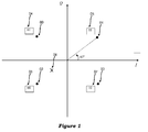
- FIG. 1 shows an example of QPSK constellation, and a possible received symbol.
- Digital data are transmitted through physical channels that normally corrupt them because of additive noise.
- the experienced fading channel imposes distortion (i.e. phase and amplitude changes).
- the received data may not coincide with the transmitted data and an equalization technique may be required to estimate the transmitted data.
- the channel coefficients are estimated prior to such equalization and assumed known by the equalizer.
- the robustness of a transmission link depends on the ability of the receiver to reliably detect the transmitted bits (i.e. transmitted 1s as 1s and 0s as 0s).
- ECCs error correction codes
- ECC decoders may provide better performance, i.e. may be able to detect the originally transmitted bits with more reliability, if they process "soft" input bit decisions (i.e. probabilities of having received 1 or 0) rather than "hard” input (i.e. received bits already interpreted to be 1 or 0). Examples include the well-known soft-input Viterbi algorithm, Low Density Parity Check Codes (LDPCC), Turbo Codes (TC). In wireless systems, soft decisions are computed based on the received symbol, the channel coefficient estimates and the noise variance estimate.
- LDPCC Low Density Parity Check Codes
- TC Turbo Codes
- MIMO Multiple-Input Multiple-Output
- MIMO transmission consists of the simultaneous transmission of T complex symbols using T transmit antennas; this way a transmit data rate of T times the data rate of a single antenna system transmitting in the same bandwidth may be obtained.
- SDM spatial division multiplexing
- the sequence of T symbols simultaneously transmitted by the multiple antennas will be also referred to as transmit sequence or transmit vector (of symbols or signals).
- each individual symbol is a sample of a PSK/QAM constellation.
- the R received symbols will be referred to as a received sequence or vector.
- R x T channel coefficients are associated with the corresponding channel links between transmit and receive antennas. They are normally estimated and grouped into a channel estimate matrix.
- T ⁇ R means a MIMO scheme featuring T transmit and R receive antennas.
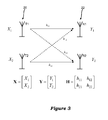
- FIGS. 2A and 2B illustrate example systems for MIMO transmission and reception.
- receivers for MIMO wireless receive as input at each receive antenna a signal made of the superposition of simultaneously transmitted symbols, each signal distorted by the channel and corrupted by noise.
- AWGN additive white Gaussian noise
- An interesting MIMO configuration derives from the combination of STBC and SDM (for brevity, SDM+STBC).
- SDM+STBC for brevity, SDM+STBC.
- T > R are used.
- a received matrix Y is given at the receiver side, wherein the entries have indices j,k denoting the receive antenna index and the time instant of the observation respectively.
- MIMO multiplex-layer interleaved detection
- An embodiment of the present invention is concerned with a method and device for performing MIMO detection.
- MIMO systems are often used in combination with multi-carrier orthogonal frequency division multiplexing (OFDM).
- OFDM systems correspond to dividing the overall information stream to be transmitted into many lower data rate streams, each one modulating a different sub-carrier of the main frequency carrier. Equivalently, the overall bandwidth is divided into many sub-bands centered on the sub-carriers. This operation makes data communication more robust under wireless multi-path fading channel, conditions and simplifies frequency equalization operations.
- OFDM systems are well known to those skilled in the art. MIMO and OFDM are key technologies for significant wireless applications of commercial interest.
- FIG. 6 Examples of typical MIMO-OFDM transmitters and receivers, including a MIMO detection apparatus, are portrayed in FIG. 6 .
- WLANs Wireless Local Area Networks
- FWA Fixed Wireless Access
- LTE Long Term Evolution
- MIMO communication receivers A potential drawback of MIMO communication receivers is a high increase in terms of computation complexity compared to single antenna systems. MIMO detection is commonly considered to be key part of MIMO receivers for its impact on performance and the high complexity cost as well.
- Maximum-Likelihood (ML) detection is often considered to be the optimal detection technique in the presence of AWGN.
- An embodiment of the present invention relates to a HW architecture design and implementation of a MIMO detector belonging to the class described in [2] and [3].
- An embodiment of the present invention targets packet-based OFDM wireless systems for static channel environment and includes an optimized design trade-off between memory consumption and processing complexity which distinguishes between channel estimate processing to be performed once per packet and received vector processing to be performed for every received OFDM symbol.
- memory usage may be reduced to a minimum if rapidly varying channel environments are to be addressed as for outdoor mobile conditions. Then, it might be necessary to update channel estimate processing for every OFDM symbol instead of once per packet.
- single carrier systems might be considered as well instead of OFDM-based ones. These cases may be considered as special cases of OFDM with one sub-carrier and as such they fall within the scope of the present disclosure.
- an embodiment of the invention allows achieving low complexity, high data rate, scalability in terms of the number of transmit antennas and flexibility versus the supported modulation order, all key factors for most MIMO wireless transmission applications.
- advantages entailed by an embodiment of the present invention concern at least two main aspects, the channel processing on one hand, the demodulation and soft output (SO) generation on the other hand.
- the channel processing on one hand
- the demodulation and soft output (SO) generation on the other hand.
- most algorithms for MIMO detection include the decomposition of the channel estimation matrix H into the product of two matrices one of which is triangular.
- QR Decomposition A common efficient implementation of such decomposition is the QR Decomposition (QRD).
- QRD HW architectures exist in the literature; a well-known example is the so-called Square-Root MMSE formulation.
- An embodiment of the present invention is concerned with an efficient HW architecture and implementation of multiple QRDs (MQRDs), one QRD for each transmit antenna, as may be required e.g. by the SO Layered ORthogonal Lattice Detector ("LORD").
- LORD SO Layered ORthogonal Lattice Detector
- VLSI Very Large Scale Integrated
- an embodiment includes a channel-estimate preprocessing unit, which computes MQRDs out of an R ⁇ T channel-estimate matrix H , with R ⁇ T .
- the MQRDs are computed through a Gram-Schmidt orthogonalization (GSO) process detailed in [2] and implemented using an optimized complexity VLSI architecture which shares the processing of common terms among the T QRDs.
- GSO Gram-Schmidt orthogonalization
- [5] is based on "K-best" SD detection and is believed to be the only one able to generate soft-output for 4x4 MIMO with 64-QAM modulation order.
- the developed integrated circuit may still suffer from the main drawback of the SD algorithm, i.e. a variable run-time detection throughput and complexity depending (among other) on the SNR.
- An embodiment of the present invention includes a HW unit to generate near-optimal bit soft-output information (LLRs) with a deterministic data rate and latency.
- LLRs near-optimal bit soft-output information
- said unit uses a method and apparatus for low-complexity bit soft-output information generation applicable to OFDM systems.
- FIGS. 1 through 19 and the various embodiments described in this disclosure are by way of illustration only and should not be construed in any way to limit the scope of this disclosure. Those skilled in the art will recognize that the various embodiments described in this disclosure may easily be modified and that such modifications fall within the scope of this disclosure.
- FIG. 1 illustrates an example QPSK constellation, wherein the four constellations symbols are denoted 00 to 03.
- the corresponding Gray-mapped couple of bits are indicated in blocks 04 to 07.
- a possible received symbol 08 is also shown, which does not coincide with any transmit symbol due to the effect of noise and distortion caused by the channel.
- FIGS. 2A and 2B illustrate an example of MIMO systems for communicating and receiving from multiple sources in accordance with this disclosure.
- these embodiments are for illustration only. Other embodiments of the systems could be used without departing from the spirit and scope of this disclosure.
- the system includes a transmitter 10 and a receiver 30.
- the transmitter 10 includes or is coupled to multiple transmit antennas 20 (denoted T1-Tn), and the receiver 30 includes or is coupled to multiple receive antennas 22 (denoted R1-Rm).
- each receive antenna 22 receives signals transmitted simultaneously by all of the transmit antennas 20.
- the system could also include multiple transmitters 10a-10t and the receiver 30.
- each of the transmitters 10a-10t includes or is coupled to a respective single transmit antenna 20.
- Each of the transmitters 10, 10a-10t in FIG. 2A and 2B represents any suitable device or component capable of generating or providing data for communication.
- the receiver 30 represents any suitable device or component capable of receiving communicated data.
- the receiver 30 includes an iterative detector and decoder 32, which detects transmit sequences of symbols from multiple sources and wherein the detector generates near-optimal bit soft-output information exploiting also the knowledge of input soft information from the outer Soft-Input Soft-Output (SISO) ECC decoder.
- the multiple sources could include a single transmitter 10 with multiple antennas 20, multiple transmitters 10a-10t with one or several antennas 20 each, or a combination thereof.
- the iterative detector and decoder 32 may operate as described in more detail below.
- the block 32 includes any hardware, software, firmware, or combination thereof for detecting multiple communications from multiple sources.
- the block 32 may be implemented in any suitable manner, such as by using an ASIC, FPGA, digital signal processor ("DSP"), microprocessor or combination or sub combination thereof.
- the block 32 may include one or more processors 34 and one or more memories 36 capable of storing data and instructions used by the processors 34.
- the interpretation of (1) is that the signal received at each of the R antennas 22 represents the superposition of T simultaneously transmitted signals from antennas 20 corrupted by multiplicative fading and AWGN.
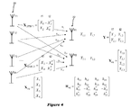
- FIG. 4 illustrates a schematic MIMO SDM+STBC system representation for four transmit and two receive antennas.
- the signal received at each of the R antennas 22 in two time instants t1 and t2 represents the superposition of T signals transmitted simultaneously from antennas 20 in two time instants and corrupted by multiplicative fading and AWGN.
- An equivalent SDM system (2) may be built for such systems in accordance with the expressions for X eq , Y eq , H eq , N eq reproduced therein.
- FIG. 5 illustrates an example soft-output MIMO detector 320 which outputs the bit LLRs corresponding to bits mapped onto the transmit sequence X, given as input the received sequence Y and the channel estimates ⁇ .
- FIGS. 6A and 6B respectively illustrate alternative embodiments of a MIMO-OFDM transmitter and receiver.
- Typical transmitter baseband digital elements/procedures are grouped as 100 .
- block 300 represents typical baseband elements/procedures of a receiver.
- the input bit stream IB is first processed by a Forward Error Correction (FEC) encoder 124, followed by a sequence of bit interleaver 126, a set of mapper blocks 106, framing and OFDM modulator blocks 114 , filter blocks 108 and digital-to-analog (D/A) converters 110 for transmission over the set of transmission antennas 20.
- FEC Forward Error Correction
- a typical receiver further includes a synchronization block 316 for enabling a coherent channel estimation by the block 312.
- a receiver typically further includes a deinterleaver 324, a FEC decoder 322, providing the final output bit stream OB.
- Deinterleaver 324 implements the reciprocal permutation law of blocks 126 .
- Any synchronization block 316 and any channel estimator 312 may be used, and any FECcode might be used in the FEC encoder 124 and FEC decoder 326, such as e.g. , Reed-Solomon, convolutional, LDPCC, and TC schemes.
- FECcode might be used in the FEC encoder 124 and FEC decoder 326, such as e.g. , Reed-Solomon, convolutional, LDPCC, and TC schemes.
- An embodiment of the present invention relates to a HW architecture design and implementation of a MIMO detector 320 that implements the functions described in [2].
- the demodulation method [2] may require consideration of all the constellation symbols as candidate symbols for the reference layer and then minimizing the ED metrics over the sequences X wherein a given bit value is "1" (or "0"). This will be referred to as “full candidate search” (FCS) in the remainder of this document, as opposed to the LCS method described below.
- FCS full candidate search
- the method is based on the following considerations:
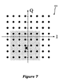
- a principle of the LCS demodulation is to explore square subsets of the constellation.
- An example is illustrated in FIG. 7 for a single transmit and receive antenna, where the received signal is represented by the cross and the subset is a square properly (and approximately) centered.
- the square subset is determined efficiently in order to reduce the probability that the true transmitted symbol falls outside the square.
- Simulation results show that performing "OFDM sub-carrier selection", i.e. dividing the sub-carriers in two groups based on the channel fading conditions, one to be demodulated through FCS and another one through LCS, may be a key to keeping a near optimal ML performance.
- the set of PAM values to be considered can be determined by centering a set of values on the ZF estimate.
- a technique based on the so-called Schnorr-Euchnerr (SE) enumeration method [4] can be used.
- T c N cycles ⁇ N DC / f clk ⁇ L c
- f clk the clock frequency
- N DC the number of data carriers per OFDM symbol
- L c the available decoding time per OFDM symbol (design constraint).
- a key point of an embodiment of the LCS method is to let the detector employ a variable number of clock cycles to demodulate different OFDM tones, still satisfying (7) on average for the N DC data carriers in an OFDM symbol.
- the sub-carrier selection criterion may be adapted to the constraints of the related HW architecture.
- sub-carrier selection steps may be performed during the channel estimate processing stage; this implies that for static channel environments like those typical e.g. of indoor WLANs, they may be performed once per packet and used to demodulate all the OFDM symbols composing the packet.
- N c,avg N c,avg .
- the meaning is that some time may be saved when demodulating the best carriers, to be used when demodulating the worst ones which may actually require N c,H >N c,avg clock cycles in practical cases.
- the actual number N c,H depends on the selected VLSI solution ( i.e. on the chosen degree of parallelism) and several cases satisfying (11) are possible; the choice depends on the desired trade-off between HW complexity and performance.
- a way to do so will be referred to as "cross demapping" (CD) in the remainder of this document.
- CD means considering also the other sets S j with j ⁇ t when computing bit LLRs relative to X t .
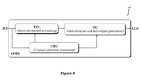
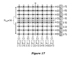
- FIG. 8 The HW architecture of an embodiment of a near-ML MIMO detector [2] is shown in FIG. 8 , where the following units are shown:
- Q j ⁇ A j is an orthonormal matrix
- R j is an upper triangular matrix
- H j Q j R j , i.e. the linear transformations are "QR" decomposition, QRDs, of H j and in one particular embodiment the YTU calculates the matrix-vector product between the Q T matrix ( i.e . the transpose of the orthonormal Q matrix result of the QRD) and the received vector Y .
- an embodiment of the present invention may be used in either OFDM-based or single carrier receivers unless otherwise stated. If OFDM receivers are dealt with, the number of OFDM sub-carriers processed in parallel represents a further degree of parallelism and such number may actually be varied in practical implementations with no loss of generality.
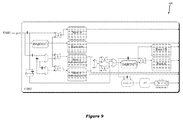
- An efficient CHU may implement a MQRD HW architecture based on the iterative decomposition principle, meaning that a generic function is decomposed into a sequence of sub-functions executed multiple times in order to reuse the same HW resources as much as possible.
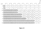
- FIG. 10 shows timing diagram associated with an embodiment of the architecture of FIG. 9 .
- the superscript of the signals in the figure refers to the sub-carrier index: the signals corresponding to the first two sub-carriers are shown.
- Each sub-carrier is processed in two clock cycles: ⁇ 1 2 , s 1,3 in parallel at the first clock cycle, and ⁇ 3 2 , s 1,4 at the second. Because of this scheduling, one ISQRT unit may be used to compute both ⁇ 1 and ⁇ 3 .
- the shown schedule may be suitable for a fully pipelined structure: successive sub-carriers may be input once every two clock cycles, for a resulting input data rate ( r MQRD ) of 1/2. It is noted that the entries of the matrices R ⁇ (1) , R ⁇ (2) may be stored as a single word in a same single-port RAM cut, thus reducing memory logic compared to that required by two separate RAM blocks.
- the unit LIST is related to the optional LCS demodulation and bit soft-output generation method. It is dedicated to the sub-carrier list management as in this case a list of N H worst OFDM sub-carriers based on the channel fading conditions are to be determined (cfr.(11)).
- the unit keeps track of a sorted list of the N H (out of N DC ) lowest values of the minimum R ⁇ 2 ⁇ T , 2 ⁇ T t h values between the two processing units corresponding to the two transmit antennas; besides, the corresponding carrier indexes are also stored. It might be convenient to keep track of each sub-carrier status through an N DC 1 bit logic array (FADINGVECT in FIG. 9 ) where a value of "0" or "1" may stand for sub-carrier to be demodulated using LCS or FCS. It is noted that the maximum data input rate ( r MQRO ) of the unit may be unaffected by the sub-carrier selection architecture.
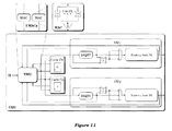
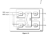
- FIG. 11 An embodiment of the corresponding architecture of the CHU is shown in FIG. 11 and is characterized by a basic level of parallelism equal to two, corresponding to the number of full QRDs to be computed.
- the core unit of said CHU is a vector multiplier unit (VMU) which includes two parallel working Multiplier and Accumulator (MAC) units. It is understood that different level of parallelism may characterize alternative embodiments.
- VMU vector multiplier unit
- MAC Accumulator
- the MAC units compute 2 R multiplications, required by the entries R ⁇ i , j t , scalar product between 2 R -element vectors. It is noted that in the whole design, the VMU is the only unit which depends on the number of receive antennas R. Therefore the design of the CHU is to be considered parameterizable with respect to the number of receive antennas.
- the number of multipliers of each MAC equals 2 R , so that each entry R ⁇ i , j t is computed in a single clock cycle.
- the MAC includes a number of multipliers K sub-multiple of 2 R . This implies that the computation of the R ⁇ i , j t terms is performed using 2 R /K clock cycles but it may bring two important advantages, both desirable for VLSI implementation:
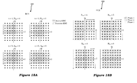
- FIG. 12 shows the timing diagram for the 4x R reference case, where t j , k ⁇ q j T ⁇ h k , where q j is the j -th column of the orthonormal matrix Q .
- the two full QRDs labeled ⁇ 1 a and ⁇ 2 b correspond to the layer ordering sequence 1,2,3,4 and 3,4,1,2, respectively; the QRD originated starting from ⁇ 1 a is labeled ⁇ 1 b and is associated with the layer permutation 1,2,4,3; similarly, the one derived from ⁇ 2 a is labeled ⁇ 2 b and corresponds to the layer sequence 3,4,2,1.
- a cache memory i.e . a bank of dedicated registers, may be used instead of a Random Access Memory (RAM) as it occupies low chip area and favors multiple simultaneous read.
- the computed R ⁇ i , j t terms may be stored in two RAM blocks, M1 and M2, operated independently by the respective units ⁇ U 1 and ⁇ U 2 . They are subject to read/write operations as the row-wise recursive computation of the entries R ⁇ i , j t , i,j >2 requires the processing of the already computed terms.
- the recursive computations translate into the feedback paths involving: two dedicated multipliers to perform the normalization of s j,k , the VMU, and the ISQRT units.
- an embodiment of the above-described CHU architecture has a basic parallelism degree of two, matched to the number of required full QRDs to be computed, and is flexible with the number of transmit antennas T : the size of the memory banks in FIG. 11 , equal to the depth of the R ⁇ ( t ) matrices, scales with T ; assigning a single MAC to the calculation of the R ⁇ i , j t terms of each sequence order makes the architecture independent from the R ⁇ ( t ) matrix size.
- the whole CHU architecture is scalable with T (and R) in terms of processing complexity. This derives from the chosen GSO formulation, which is suitable for a modular HW architecture approach i.e. the associated CHU architecture is characterized by a scalable complexity to larger T x R MIMO dimensions starting from the basic 2x2 modules.
- MQRDs are efficiently computed through low-complexity and time-shared based HW architectures.
- the DU performs demodulation and bit soft-output generation.
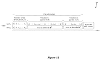
- the steps performed by the DU, to be repeated for every reference layer, are:
- FIG. 13 illustrates an example architecture of the DU: it includes a lattice search unit (LSU), an optional cross-demapping unit (CDU) and a bit demapping unit (DMU).
- LSU lattice search unit
- CDU cross-demapping unit
- DMU bit demapping unit
- the role of the LSU is to perform the "constellation sweeping" i.e . a procedure consisting of:
- FIG. 14 graphically represents an example computation of the ED for a 4x R transmission scheme and generic constellation of size S as a tree traversal.
- T parallel LSUs one for each reference layer, are instantiated within the DU.
- the DU includes one LSU which sequentially computes the EDs associated with the T sets of candidate symbols of the respective reference layers: the throughput decreases by a factor of T , but the area saving is of the same order of magnitude.
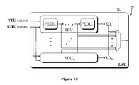
- FIG. 15 shows the architecture of a LSU. It is scalable with the number ( N ED ) of ED units (EDUs), wherein each EDU computes a single ED. Each ED is the result of the summation of T partial Euclidean distances (PEDs).
- a PED is defined in an embodiment as the summation of the two independent squares related to the I and Q of a given complex symbol ( i.e . a single term of eq. (57) of [2]).
- each EDU includes T PEDUs.
- EDU embodiments are possible including K PEDUs, where K is an integer sub-multiple of T.
- An ED metric is then output in TlK iterative loops and as many clock cycles.
- the LSU of Fig. 15 is parameterizable in terms of T : an architecture sized for a T x R MIMO configuration may handle T 'x R schemes as well, where T ' ⁇ T .
- the output of the LSU is given by the multiplexer of Fig. 15 , driven by the number of active antennas N T .
- An embodiment of an LSU architecture implements a constellation sweeping method based on [2], where M 2 EDs are to be computed to demodulate M 2 -QAM constellation symbols.
- N ED parallel EDUs per antenna are instantiated, each one computing an ED metric in one clock cycle.
- N ED is an integer sub-multiple of M 2 .
- N ED 16.
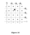
- the proposed flow is to divide them in two subsets of N EO /2 units (the gray rectangles in figure), spanning the positive and negative Q semi-axes as indicated by the arrows.
- N ED l2 ED metrics are computed for a same positive Q value and all / PAM values; similarly, at the same clock cycle, N EO /2 ED metrics are computed for a negative Q value.
- an embodiment of the described LSU architecture generates soft-output with a deterministic data rate and latency and this may represent a significant advantage compared to the state of the art of near-ML detection VLSI implementations.
- N ED may be determined based on the largest modulation order to be supported; flexibility is still present as lower order modulations may be handled simply by disabling the unused ( N ED -M ) EDUs (thus saving power).
- Spatial DFE is an operation performed by the LSU in correspondence with every candidate symbol of the reference layer(s). It consists of performing a quantization (or "slicing") operation to the closest PAM value in order to determine symbol estimates for the non-reference layers (see also [2], eq. (26)):
- x ⁇ j round ⁇ y ⁇ j - ⁇ k > j ⁇ R ⁇ j , k x ⁇ k R ⁇ j , j
- a multiplication of the numerator in (20) by 1/ R ⁇ j,j may be needed.
- anefficient embodiment avoids such multiplication by determining the PAM value x ⁇ j such that R ⁇ j , j x ⁇ j is the closest to y ⁇ j - ⁇ k > j R ⁇ j , k x ⁇ k .
- the sets depend on the demapping rule and the bit position within the symbol, the related HW structure may not be straightforward.
- An embodiment of a DMU architecture solves the above described issue and is based on a two-step process.
- the ED metrics are minimized and stored in corresponding registers as a function of the associated PAM value of the reference layer (two independent minimizations for both I and Q for a total of 2M registers).
- the DMU of FIG. 13 performs bit demapping according to a given input mapping (and demapping counterpart) rule.
- the LLR corresponding to a given bit of the I (or Q ) component is determined by performing a further minimization of the M /2 values stored in the corresponding registers.
- each DMU performs bit demapping according to the well-known Gray mapping rule, though it is intended that any bit mapping rule could be used without limiting the scope of the present disclosure.
- the embodiment consists of a HW architecture of LSU implementing the LCS demodulation method (7)-(11).
- N ED ⁇ n EDUs are instantiated. They work in parallel and process symbols along rows, one per clock cycle. Then, n clock cycles are required to span n 2 points. It is noted that ( N ED -n ) EDUs do not need to remain active and may be disabled in order to save power.
- FCS CASE-A M 2 -QAM constellations
- N ED ⁇ M EDUs are instantiated
- the process may be divided into three phases, identified by the arrows showing the direction of processing and by the related subsets of symbols having different colour in figure:
- Table 1 summarizes the LSU latencies for N ED ranging from 4 to 8 based on the above-mentioned constellation sweeping method and on (7)-(11).
- Table 1 N ED n 2 N c,H N H N c,avg 4 16 16 8 5.84 5 25 14 5 5.86 6 25 12 7 5.94 8 25 8 17 5.98
- Table 2 reports the VLSI area results obtained using alternative LSUs implementing the two constellation sweeping processes previously described.
- the area estimates refer to 65 nm CMOS technology.
- An embodiment of the LCS architecture achieves area reduction of 63% compared to the FCS case.
- the LLR reliability may be improved extending the number of candidate transmit sequences, see (13).
- a potential drawback is the introduction of interdependence between the T minimizations performed by the LSU in order to compute the LLRs of the bits corresponding to the T symbols transmitted by the related transmit antennas.
- the related operations are included in the "cross demapping unit” (CDU) unit of FIG. 13 .
- the operations performed by the unit refer to par. [80], meaning that a given LSU, when computing the EDs over a given set of candidate symbols for a reference layer, keep track of the minimum found ED value also as function of the estimate value for the non-reference layers.
- estimate values are not known a-priori in general and are determined at run-time, for example through spatial DFE starting from the candidate value of the reference layer, as of an embodiment described previously.
- the architecture associates with each of the N ED ED values, a M -cell vector for each of the T -1 non-reference transmit symbols (one cell for each possible PAM value of the corresponding symbol estimate).
- Each ED value is stored into the cells corresponding to the related non-reference layer PAM value estimates (the other M -1 cells are filled with an initialisation value).
- M comparators processing N ED inputs each compare the values stored in the cells associated with a same PAM value and output M minimum ED values, one for each possible PAM value.
- the minimum ED associated with the PAM values of the non-reference layer estimates will be also stored in the M cells.
- a last operation performed by the CDU, prior to LLRs computation may be the cross-comparison of the minimum ED values associated with the PAM values of the reference layers output by the LSU as a result of the constellation sweeping, with the values stored in the corresponding cells determined as a consequence of the cross-demapping operations described above.
- the final minimum values, one for each PAM element, will be the output values of the CDU to be passed to the DMU.
- HW architecture of a near-optimal soft-output MIMO detector characterized by scalability in terms of the number of transmit antennas, high throughput, low complexity, flexibility versus the supported modulation order has been disclosed.
Landscapes
- Engineering & Computer Science (AREA)
- Computer Networks & Wireless Communication (AREA)
- Signal Processing (AREA)
- Power Engineering (AREA)
- Radio Transmission System (AREA)
- Mobile Radio Communication Systems (AREA)
Applications Claiming Priority (1)
| Application Number | Priority Date | Filing Date | Title |
|---|---|---|---|
| US24004509P | 2009-09-04 | 2009-09-04 |
Publications (3)
| Publication Number | Publication Date |
|---|---|
| EP2293483A2 true EP2293483A2 (de) | 2011-03-09 |
| EP2293483A3 EP2293483A3 (de) | 2014-06-25 |
| EP2293483B1 EP2293483B1 (de) | 2016-07-27 |
Family
ID=42738835
Family Applications (1)
| Application Number | Title | Priority Date | Filing Date |
|---|---|---|---|
| EP10174589.1A Active EP2293483B1 (de) | 2009-09-04 | 2010-08-31 | Verfahren und Vorrichtung zur Soft-Ausgabe-Detektion in einem Kommunikationssystemen mit mehreren Antennen. |
Country Status (2)
| Country | Link |
|---|---|
| US (1) | US8588322B2 (de) |
| EP (1) | EP2293483B1 (de) |
Cited By (3)
| Publication number | Priority date | Publication date | Assignee | Title |
|---|---|---|---|---|
| WO2015070804A1 (en) * | 2013-11-14 | 2015-05-21 | Mediatek Singapore Pte. Ltd. | Large-scale fading coefficient estimation in wireless massive mimo systems |
| CN111478867A (zh) * | 2020-03-23 | 2020-07-31 | 比科奇微电子(杭州)有限公司 | 信号处理方法、装置、存储介质、处理器及电子装置 |
| CN118400074A (zh) * | 2024-06-26 | 2024-07-26 | 上海三菲半导体有限公司 | 一种接收机及信号处理方法 |
Families Citing this family (10)
| Publication number | Priority date | Publication date | Assignee | Title |
|---|---|---|---|---|
| JP5578617B2 (ja) | 2010-10-18 | 2014-08-27 | パナソニック インテレクチュアル プロパティ コーポレーション オブ アメリカ | 送信方法、送信装置、受信方法および受信装置 |
| US8774146B2 (en) * | 2011-12-19 | 2014-07-08 | Alcatel Lucent | Large-scale antenna method and apparatus of wireless communication with suppression of intercell interference |
| US9066247B2 (en) * | 2013-01-28 | 2015-06-23 | Intel Mobile Communications GmbH | Communication devices and methods for signal detection |
| US9071471B2 (en) * | 2013-03-14 | 2015-06-30 | Nec Laboratories America, Inc. | Low-complexity estimation of QAM symbols and constellations |
| KR20150117155A (ko) * | 2014-04-09 | 2015-10-19 | 한국전자통신연구원 | 다중입력 다중출력 통신 시스템의 연판정 검출 방법 및 장치 |
| EP3107235B1 (de) * | 2015-06-16 | 2019-08-14 | Mitsubishi Electric R&D Centre Europe B.V. | Verfahren zur berechnung von wahrscheinlichkeiten in einem verfahren zur rekonstruktion von decodierten informationsworten |
| US10171207B2 (en) * | 2017-04-26 | 2019-01-01 | Cavium, Llc | Methods and apparatus for control bit detection |
| CN110677179B (zh) * | 2019-10-09 | 2020-11-10 | 河北科技大学 | 接收天线选择方法、装置及终端设备 |
| CN112929300B (zh) * | 2019-12-05 | 2024-05-03 | 深圳市中兴微电子技术有限公司 | 一种数据处理装置、方法、基站和存储介质 |
| CN115037340B (zh) * | 2022-06-07 | 2023-11-07 | 网络通信与安全紫金山实验室 | 信号检测方法、装置、电子设备及存储介质 |
Citations (1)
| Publication number | Priority date | Publication date | Assignee | Title |
|---|---|---|---|---|
| WO2007012053A1 (en) | 2005-07-20 | 2007-01-25 | Stmicroelectronics, S.R.L. | Apparatus and method for detecting communications from multiple sources |
Family Cites Families (11)
| Publication number | Priority date | Publication date | Assignee | Title |
|---|---|---|---|---|
| US7245666B1 (en) * | 2003-04-03 | 2007-07-17 | Qualcomm, Inc. | Soft symbol decoding for MIMO communication systems with reduced search complexity |
| FR2863422A1 (fr) * | 2003-12-04 | 2005-06-10 | France Telecom | Procede d'emission multi-antennes d'un signal precode lineairement,procede de reception, signal et dispositifs correspondants |
| EP1545082A3 (de) * | 2003-12-17 | 2005-08-03 | Kabushiki Kaisha Toshiba | Verfahren und Apparat zum Dekodieren von Signalen |
| US8169889B2 (en) * | 2004-02-18 | 2012-05-01 | Qualcomm Incorporated | Transmit diversity and spatial spreading for an OFDM-based multi-antenna communication system |
| US7802172B2 (en) * | 2005-06-20 | 2010-09-21 | Stmicroelectronics, Inc. | Variable-rate low-density parity check codes with constant blocklength |
| EP2119155A2 (de) * | 2007-03-14 | 2009-11-18 | STMicroelectronics S.r.l. | Verfahren und vorrichtung für mehrantennenkommunikation, computerprogrammprodukt dafür |
| EP1971063B1 (de) * | 2007-03-14 | 2018-10-10 | STMicroelectronics S.r.l. | Verfahren und Vorrichtung für Mehrantennenkommunikation, zugehörige Systeme und Computerprogramm |
| CN101796785B (zh) * | 2007-07-06 | 2013-06-05 | 特莱登特微系统(远东)有限公司 | 主要用于Nordstrom-Robinson码译码器的设备和方法 |
| TWI424699B (zh) * | 2008-08-31 | 2014-01-21 | Realtek Semiconductor Corp | 多層叢集式多輸入多輸出偵測方法及相關多輸入多輸出偵測器 |
| KR101158096B1 (ko) * | 2008-11-18 | 2012-06-22 | 삼성전자주식회사 | 다중 송수신 안테나 시스템에서 서로 다른 변조 차수를 갖는 복수의 레이어의 재정렬 방법, 신호 검출 방법 및 그 수신 장치 |
| US8396157B2 (en) * | 2009-05-14 | 2013-03-12 | Futurewei Technologies, Inc. | Probability based MIMO mode selection and switching system and method for wireless systems |
-
2010
- 2010-08-31 EP EP10174589.1A patent/EP2293483B1/de active Active
- 2010-09-02 US US12/875,100 patent/US8588322B2/en active Active
Patent Citations (1)
| Publication number | Priority date | Publication date | Assignee | Title |
|---|---|---|---|---|
| WO2007012053A1 (en) | 2005-07-20 | 2007-01-25 | Stmicroelectronics, S.R.L. | Apparatus and method for detecting communications from multiple sources |
Non-Patent Citations (4)
| Title |
|---|
| A. STEPHENS ET AL.: "Draft Amendment to [....] -Part 11: Wireless LAN Medium Access Control (MAC) and Physical Layer (PHY) specifications: Enhancements for Higher Throughput", IEEE P802.1 NTM/D8.0 |
| C. STUDER; A. BURG; H. BÖLCSKEI: "Soft-Output Sphere Decoding: Algorithms and VLSI Implementation", IEEE JOURNAL ON SELECTED AREAS IN COMMUNICATIONS, vol. 26, no. 2, February 2008 (2008-02-01) |
| M. SITI; P. FITZ: "A novel soft-output layered orthogonal lattice detector for multiple antenna communications", PROC. IEEE INT. CONF. ON COMMUNICATIONS, June 2006 (2006-06-01) |
| S. CHEN; T. ZHANG: "Low Power Soft-Output Signal Detector Design for Wireless MIMO Communication System", ISLPED'07, 27 August 2007 (2007-08-27) |
Cited By (7)
| Publication number | Priority date | Publication date | Assignee | Title |
|---|---|---|---|---|
| WO2015070804A1 (en) * | 2013-11-14 | 2015-05-21 | Mediatek Singapore Pte. Ltd. | Large-scale fading coefficient estimation in wireless massive mimo systems |
| CN105745893A (zh) * | 2013-11-14 | 2016-07-06 | 联发科技(新加坡)私人有限公司 | 无线大量mimo系统中大尺度衰落系数估计 |
| US9647734B2 (en) | 2013-11-14 | 2017-05-09 | Mediatek Singapore Pte. Ltd. | Large-scale fading coefficient estimation in wireless massive MIMO systems |
| CN105745893B (zh) * | 2013-11-14 | 2019-03-15 | 联发科技(新加坡)私人有限公司 | 无线大量mimo系统中大尺度衰落系数估计方法及行动台 |
| CN111478867A (zh) * | 2020-03-23 | 2020-07-31 | 比科奇微电子(杭州)有限公司 | 信号处理方法、装置、存储介质、处理器及电子装置 |
| CN111478867B (zh) * | 2020-03-23 | 2023-01-31 | 比科奇微电子(杭州)有限公司 | 信号处理方法、装置、存储介质、处理器及电子装置 |
| CN118400074A (zh) * | 2024-06-26 | 2024-07-26 | 上海三菲半导体有限公司 | 一种接收机及信号处理方法 |
Also Published As
| Publication number | Publication date |
|---|---|
| EP2293483A3 (de) | 2014-06-25 |
| EP2293483B1 (de) | 2016-07-27 |
| US8588322B2 (en) | 2013-11-19 |
| US20110058632A1 (en) | 2011-03-10 |
Similar Documents
| Publication | Publication Date | Title |
|---|---|---|
| EP2293483B1 (de) | Verfahren und Vorrichtung zur Soft-Ausgabe-Detektion in einem Kommunikationssystemen mit mehreren Antennen. | |
| EP2200240B1 (de) | Verfahren und Vorrichtung zur annähernd optimalen Berechnung von Zuverlässigkeitsinformationen in Kommunikationssystemen mit mehreren Antennen und iterativer Detektion und Dekodierung | |
| EP1905182B1 (de) | Verfahren und vorrichtung zur erfassung von kommunikation aus mehreren quellen | |
| US8462867B2 (en) | Near soft-output maximum-likelihood detection for multiple-input multiple-output systems | |
| EP2245808B1 (de) | Baumpositions-Adaptiv-Softausgabe-M-Algorithmus-Empfängerstrukturen | |
| US8064548B2 (en) | Adaptive MaxLogMAP-type receiver structures | |
| US20090285323A1 (en) | Adaptive soft output m-algorithm receiver structures | |
| EP1971063A1 (de) | Verfahren und Vorrichtung für Mehrantennenkommunikation, zugehörige Systeme und Computerprogramm | |
| CN101411086A (zh) | 提供mimo接收器的装置、方法和计算机程序产品 | |
| EP2149241A1 (de) | Adaptive m-algorithmus-empfängerstrukturen mit soft-output | |
| US9660709B1 (en) | Systems and methods for calculating log-likelihood ratios in a MIMO detector | |
| WO2010033524A1 (en) | Methods and systems for hybrid mimo decoding | |
| KR20110056333A (ko) | Qr 분해를 이용하는 mms mimo 디코더 | |
| CN101453444A (zh) | 星座图简化装置和方法、接收机 | |
| US8374274B2 (en) | Methods and systems using norm approximation for maximum likelihood MIMO decoding | |
| US7978779B2 (en) | Tone-interleaved coded modulation scheme for MIMO OFDM communication | |
| Cupaiuolo et al. | Low-complexity high throughput VLSI architecture of soft-output ML MIMO detector | |
| US9917723B2 (en) | Efficient methods and recursive/scalable circuit architectures for QAM symbol mean and variance estimations | |
| Choi et al. | MIMO soft near-ML demodulation with fixed low-complexity candidate selection | |
| Tomasoni et al. | A hardware oriented, low-complexity LORD MIMO detector | |
| Nasser et al. | Robustness of MIMO-OFDM schemes for future digital TV to carrier frequency offset | |
| WO2008134666A1 (en) | Systems and methods for low-complexity maximum-likelihood mimo detection |
Legal Events
| Date | Code | Title | Description |
|---|---|---|---|
| PUAI | Public reference made under article 153(3) epc to a published international application that has entered the european phase |
Free format text: ORIGINAL CODE: 0009012 |
|
| AK | Designated contracting states |
Kind code of ref document: A2 Designated state(s): AL AT BE BG CH CY CZ DE DK EE ES FI FR GB GR HR HU IE IS IT LI LT LU LV MC MK MT NL NO PL PT RO SE SI SK SM TR |
|
| AX | Request for extension of the european patent |
Extension state: BA ME RS |
|
| RAP1 | Party data changed (applicant data changed or rights of an application transferred) |
Owner name: POLITECNICO DI MILANO Owner name: STMICROELECTRONICS SRL |
|
| PUAL | Search report despatched |
Free format text: ORIGINAL CODE: 0009013 |
|
| AK | Designated contracting states |
Kind code of ref document: A3 Designated state(s): AL AT BE BG CH CY CZ DE DK EE ES FI FR GB GR HR HU IE IS IT LI LT LU LV MC MK MT NL NO PL PT RO SE SI SK SM TR |
|
| AX | Request for extension of the european patent |
Extension state: BA ME RS |
|
| RIC1 | Information provided on ipc code assigned before grant |
Ipc: H04L 1/06 20060101AFI20140522BHEP Ipc: H04L 25/03 20060101ALI20140522BHEP Ipc: H04L 25/02 20060101ALI20140522BHEP |
|
| 17P | Request for examination filed |
Effective date: 20141223 |
|
| RBV | Designated contracting states (corrected) |
Designated state(s): AL AT BE BG CH CY CZ DE DK EE ES FI FR GB GR HR HU IE IS IT LI LT LU LV MC MK MT NL NO PL PT RO SE SI SK SM TR |
|
| RAP1 | Party data changed (applicant data changed or rights of an application transferred) |
Owner name: STMICROELECTRONICS SRL |
|
| 17Q | First examination report despatched |
Effective date: 20150702 |
|
| GRAP | Despatch of communication of intention to grant a patent |
Free format text: ORIGINAL CODE: EPIDOSNIGR1 |
|
| INTG | Intention to grant announced |
Effective date: 20160226 |
|
| GRAS | Grant fee paid |
Free format text: ORIGINAL CODE: EPIDOSNIGR3 |
|
| GRAA | (expected) grant |
Free format text: ORIGINAL CODE: 0009210 |
|
| AK | Designated contracting states |
Kind code of ref document: B1 Designated state(s): AL AT BE BG CH CY CZ DE DK EE ES FI FR GB GR HR HU IE IS IT LI LT LU LV MC MK MT NL NO PL PT RO SE SI SK SM TR |
|
| REG | Reference to a national code |
Ref country code: GB Ref legal event code: FG4D |
|
| REG | Reference to a national code |
Ref country code: CH Ref legal event code: EP |
|
| REG | Reference to a national code |
Ref country code: AT Ref legal event code: REF Ref document number: 816561 Country of ref document: AT Kind code of ref document: T Effective date: 20160815 |
|
| REG | Reference to a national code |
Ref country code: FR Ref legal event code: PLFP Year of fee payment: 7 |
|
| REG | Reference to a national code |
Ref country code: IE Ref legal event code: FG4D |
|
| REG | Reference to a national code |
Ref country code: DE Ref legal event code: R096 Ref document number: 602010034991 Country of ref document: DE |
|
| REG | Reference to a national code |
Ref country code: LT Ref legal event code: MG4D |
|
| REG | Reference to a national code |
Ref country code: NL Ref legal event code: MP Effective date: 20160727 |
|
| REG | Reference to a national code |
Ref country code: AT Ref legal event code: MK05 Ref document number: 816561 Country of ref document: AT Kind code of ref document: T Effective date: 20160727 |
|
| PG25 | Lapsed in a contracting state [announced via postgrant information from national office to epo] |
Ref country code: BE Free format text: LAPSE BECAUSE OF NON-PAYMENT OF DUE FEES Effective date: 20160831 |
|
| PG25 | Lapsed in a contracting state [announced via postgrant information from national office to epo] |
Ref country code: IT Free format text: LAPSE BECAUSE OF FAILURE TO SUBMIT A TRANSLATION OF THE DESCRIPTION OR TO PAY THE FEE WITHIN THE PRESCRIBED TIME-LIMIT Effective date: 20160727 Ref country code: NL Free format text: LAPSE BECAUSE OF FAILURE TO SUBMIT A TRANSLATION OF THE DESCRIPTION OR TO PAY THE FEE WITHIN THE PRESCRIBED TIME-LIMIT Effective date: 20160727 Ref country code: NO Free format text: LAPSE BECAUSE OF FAILURE TO SUBMIT A TRANSLATION OF THE DESCRIPTION OR TO PAY THE FEE WITHIN THE PRESCRIBED TIME-LIMIT Effective date: 20161027 Ref country code: LT Free format text: LAPSE BECAUSE OF FAILURE TO SUBMIT A TRANSLATION OF THE DESCRIPTION OR TO PAY THE FEE WITHIN THE PRESCRIBED TIME-LIMIT Effective date: 20160727 Ref country code: IS Free format text: LAPSE BECAUSE OF FAILURE TO SUBMIT A TRANSLATION OF THE DESCRIPTION OR TO PAY THE FEE WITHIN THE PRESCRIBED TIME-LIMIT Effective date: 20161127 Ref country code: FI Free format text: LAPSE BECAUSE OF FAILURE TO SUBMIT A TRANSLATION OF THE DESCRIPTION OR TO PAY THE FEE WITHIN THE PRESCRIBED TIME-LIMIT Effective date: 20160727 Ref country code: HR Free format text: LAPSE BECAUSE OF FAILURE TO SUBMIT A TRANSLATION OF THE DESCRIPTION OR TO PAY THE FEE WITHIN THE PRESCRIBED TIME-LIMIT Effective date: 20160727 |
|
| PG25 | Lapsed in a contracting state [announced via postgrant information from national office to epo] |
Ref country code: BE Free format text: LAPSE BECAUSE OF FAILURE TO SUBMIT A TRANSLATION OF THE DESCRIPTION OR TO PAY THE FEE WITHIN THE PRESCRIBED TIME-LIMIT Effective date: 20160727 Ref country code: PL Free format text: LAPSE BECAUSE OF FAILURE TO SUBMIT A TRANSLATION OF THE DESCRIPTION OR TO PAY THE FEE WITHIN THE PRESCRIBED TIME-LIMIT Effective date: 20160727 Ref country code: GR Free format text: LAPSE BECAUSE OF FAILURE TO SUBMIT A TRANSLATION OF THE DESCRIPTION OR TO PAY THE FEE WITHIN THE PRESCRIBED TIME-LIMIT Effective date: 20161028 Ref country code: LV Free format text: LAPSE BECAUSE OF FAILURE TO SUBMIT A TRANSLATION OF THE DESCRIPTION OR TO PAY THE FEE WITHIN THE PRESCRIBED TIME-LIMIT Effective date: 20160727 Ref country code: AT Free format text: LAPSE BECAUSE OF FAILURE TO SUBMIT A TRANSLATION OF THE DESCRIPTION OR TO PAY THE FEE WITHIN THE PRESCRIBED TIME-LIMIT Effective date: 20160727 Ref country code: ES Free format text: LAPSE BECAUSE OF FAILURE TO SUBMIT A TRANSLATION OF THE DESCRIPTION OR TO PAY THE FEE WITHIN THE PRESCRIBED TIME-LIMIT Effective date: 20160727 Ref country code: SE Free format text: LAPSE BECAUSE OF FAILURE TO SUBMIT A TRANSLATION OF THE DESCRIPTION OR TO PAY THE FEE WITHIN THE PRESCRIBED TIME-LIMIT Effective date: 20160727 Ref country code: PT Free format text: LAPSE BECAUSE OF FAILURE TO SUBMIT A TRANSLATION OF THE DESCRIPTION OR TO PAY THE FEE WITHIN THE PRESCRIBED TIME-LIMIT Effective date: 20161128 |
|
| REG | Reference to a national code |
Ref country code: CH Ref legal event code: PL |
|
| PG25 | Lapsed in a contracting state [announced via postgrant information from national office to epo] |
Ref country code: LI Free format text: LAPSE BECAUSE OF NON-PAYMENT OF DUE FEES Effective date: 20160831 Ref country code: RO Free format text: LAPSE BECAUSE OF FAILURE TO SUBMIT A TRANSLATION OF THE DESCRIPTION OR TO PAY THE FEE WITHIN THE PRESCRIBED TIME-LIMIT Effective date: 20160727 Ref country code: MC Free format text: LAPSE BECAUSE OF FAILURE TO SUBMIT A TRANSLATION OF THE DESCRIPTION OR TO PAY THE FEE WITHIN THE PRESCRIBED TIME-LIMIT Effective date: 20160727 Ref country code: EE Free format text: LAPSE BECAUSE OF FAILURE TO SUBMIT A TRANSLATION OF THE DESCRIPTION OR TO PAY THE FEE WITHIN THE PRESCRIBED TIME-LIMIT Effective date: 20160727 Ref country code: CH Free format text: LAPSE BECAUSE OF NON-PAYMENT OF DUE FEES Effective date: 20160831 |
|
| REG | Reference to a national code |
Ref country code: DE Ref legal event code: R097 Ref document number: 602010034991 Country of ref document: DE |
|
| PG25 | Lapsed in a contracting state [announced via postgrant information from national office to epo] |
Ref country code: CZ Free format text: LAPSE BECAUSE OF FAILURE TO SUBMIT A TRANSLATION OF THE DESCRIPTION OR TO PAY THE FEE WITHIN THE PRESCRIBED TIME-LIMIT Effective date: 20160727 Ref country code: SK Free format text: LAPSE BECAUSE OF FAILURE TO SUBMIT A TRANSLATION OF THE DESCRIPTION OR TO PAY THE FEE WITHIN THE PRESCRIBED TIME-LIMIT Effective date: 20160727 Ref country code: DK Free format text: LAPSE BECAUSE OF FAILURE TO SUBMIT A TRANSLATION OF THE DESCRIPTION OR TO PAY THE FEE WITHIN THE PRESCRIBED TIME-LIMIT Effective date: 20160727 Ref country code: SM Free format text: LAPSE BECAUSE OF FAILURE TO SUBMIT A TRANSLATION OF THE DESCRIPTION OR TO PAY THE FEE WITHIN THE PRESCRIBED TIME-LIMIT Effective date: 20160727 Ref country code: BG Free format text: LAPSE BECAUSE OF FAILURE TO SUBMIT A TRANSLATION OF THE DESCRIPTION OR TO PAY THE FEE WITHIN THE PRESCRIBED TIME-LIMIT Effective date: 20161027 |
|
| REG | Reference to a national code |
Ref country code: IE Ref legal event code: MM4A |
|
| PLBE | No opposition filed within time limit |
Free format text: ORIGINAL CODE: 0009261 |
|
| STAA | Information on the status of an ep patent application or granted ep patent |
Free format text: STATUS: NO OPPOSITION FILED WITHIN TIME LIMIT |
|
| GBPC | Gb: european patent ceased through non-payment of renewal fee |
Effective date: 20161027 |
|
| 26N | No opposition filed |
Effective date: 20170502 |
|
| REG | Reference to a national code |
Ref country code: FR Ref legal event code: PLFP Year of fee payment: 8 |
|
| PG25 | Lapsed in a contracting state [announced via postgrant information from national office to epo] |
Ref country code: GB Free format text: LAPSE BECAUSE OF NON-PAYMENT OF DUE FEES Effective date: 20161027 Ref country code: IE Free format text: LAPSE BECAUSE OF NON-PAYMENT OF DUE FEES Effective date: 20160831 |
|
| PG25 | Lapsed in a contracting state [announced via postgrant information from national office to epo] |
Ref country code: SI Free format text: LAPSE BECAUSE OF FAILURE TO SUBMIT A TRANSLATION OF THE DESCRIPTION OR TO PAY THE FEE WITHIN THE PRESCRIBED TIME-LIMIT Effective date: 20160727 Ref country code: LU Free format text: LAPSE BECAUSE OF NON-PAYMENT OF DUE FEES Effective date: 20160831 |
|
| PG25 | Lapsed in a contracting state [announced via postgrant information from national office to epo] |
Ref country code: HU Free format text: LAPSE BECAUSE OF FAILURE TO SUBMIT A TRANSLATION OF THE DESCRIPTION OR TO PAY THE FEE WITHIN THE PRESCRIBED TIME-LIMIT; INVALID AB INITIO Effective date: 20100831 Ref country code: CY Free format text: LAPSE BECAUSE OF FAILURE TO SUBMIT A TRANSLATION OF THE DESCRIPTION OR TO PAY THE FEE WITHIN THE PRESCRIBED TIME-LIMIT Effective date: 20160727 |
|
| PG25 | Lapsed in a contracting state [announced via postgrant information from national office to epo] |
Ref country code: MT Free format text: LAPSE BECAUSE OF NON-PAYMENT OF DUE FEES Effective date: 20160831 Ref country code: MK Free format text: LAPSE BECAUSE OF FAILURE TO SUBMIT A TRANSLATION OF THE DESCRIPTION OR TO PAY THE FEE WITHIN THE PRESCRIBED TIME-LIMIT Effective date: 20160727 Ref country code: TR Free format text: LAPSE BECAUSE OF FAILURE TO SUBMIT A TRANSLATION OF THE DESCRIPTION OR TO PAY THE FEE WITHIN THE PRESCRIBED TIME-LIMIT Effective date: 20160727 |
|
| REG | Reference to a national code |
Ref country code: FR Ref legal event code: PLFP Year of fee payment: 9 |
|
| PG25 | Lapsed in a contracting state [announced via postgrant information from national office to epo] |
Ref country code: AL Free format text: LAPSE BECAUSE OF FAILURE TO SUBMIT A TRANSLATION OF THE DESCRIPTION OR TO PAY THE FEE WITHIN THE PRESCRIBED TIME-LIMIT Effective date: 20160727 |
|
| PGFP | Annual fee paid to national office [announced via postgrant information from national office to epo] |
Ref country code: FR Payment date: 20200721 Year of fee payment: 11 |
|
| PG25 | Lapsed in a contracting state [announced via postgrant information from national office to epo] |
Ref country code: FR Free format text: LAPSE BECAUSE OF NON-PAYMENT OF DUE FEES Effective date: 20210831 |
|
| PGFP | Annual fee paid to national office [announced via postgrant information from national office to epo] |
Ref country code: DE Payment date: 20250724 Year of fee payment: 16 |