EP2293245A1 - Providing a 2-dimensional CT image corresponding to a 2-dimensional ultrasound image - Google Patents
Providing a 2-dimensional CT image corresponding to a 2-dimensional ultrasound image Download PDFInfo
- Publication number
- EP2293245A1 EP2293245A1 EP10170226A EP10170226A EP2293245A1 EP 2293245 A1 EP2293245 A1 EP 2293245A1 EP 10170226 A EP10170226 A EP 10170226A EP 10170226 A EP10170226 A EP 10170226A EP 2293245 A1 EP2293245 A1 EP 2293245A1
- Authority
- EP
- European Patent Office
- Prior art keywords
- dimensional
- images
- ultrasound image
- image
- voxels
- Prior art date
- Legal status (The legal status is an assumption and is not a legal conclusion. Google has not performed a legal analysis and makes no representation as to the accuracy of the status listed.)
- Ceased
Links
- 238000002604 ultrasonography Methods 0.000 title claims abstract description 203
- 238000000034 method Methods 0.000 claims abstract description 23
- 210000004204 blood vessel Anatomy 0.000 claims description 83
- 238000000605 extraction Methods 0.000 claims description 45
- 239000000284 extract Substances 0.000 claims description 19
- 230000000877 morphologic effect Effects 0.000 claims description 9
- 238000001514 detection method Methods 0.000 claims description 7
- 230000000873 masking effect Effects 0.000 claims description 7
- 238000007670 refining Methods 0.000 claims description 7
- 238000004458 analytical method Methods 0.000 claims description 6
- 239000000523 sample Substances 0.000 description 37
- 230000005540 biological transmission Effects 0.000 description 12
- 238000010586 diagram Methods 0.000 description 8
- 239000011159 matrix material Substances 0.000 description 6
- 210000004185 liver Anatomy 0.000 description 5
- 230000001131 transforming effect Effects 0.000 description 3
- 230000010339 dilation Effects 0.000 description 2
- 230000003628 erosive effect Effects 0.000 description 2
- 238000001914 filtration Methods 0.000 description 2
- 230000000241 respiratory effect Effects 0.000 description 2
- 230000011218 segmentation Effects 0.000 description 2
- 238000003325 tomography Methods 0.000 description 2
- 210000001631 vena cava inferior Anatomy 0.000 description 2
- 230000003044 adaptive effect Effects 0.000 description 1
- 239000008280 blood Substances 0.000 description 1
- 210000004369 blood Anatomy 0.000 description 1
- 238000010968 computed tomography angiography Methods 0.000 description 1
- 230000001066 destructive effect Effects 0.000 description 1
- 210000002989 hepatic vein Anatomy 0.000 description 1
- 210000003734 kidney Anatomy 0.000 description 1
- 238000012986 modification Methods 0.000 description 1
- 230000004048 modification Effects 0.000 description 1
- 210000003240 portal vein Anatomy 0.000 description 1
- 230000029058 respiratory gaseous exchange Effects 0.000 description 1
- 238000001356 surgical procedure Methods 0.000 description 1
- 210000001835 viscera Anatomy 0.000 description 1
Images


Classifications
-
- A—HUMAN NECESSITIES
- A61—MEDICAL OR VETERINARY SCIENCE; HYGIENE
- A61B—DIAGNOSIS; SURGERY; IDENTIFICATION
- A61B8/00—Diagnosis using ultrasonic, sonic or infrasonic waves
-
- A—HUMAN NECESSITIES
- A61—MEDICAL OR VETERINARY SCIENCE; HYGIENE
- A61B—DIAGNOSIS; SURGERY; IDENTIFICATION
- A61B8/00—Diagnosis using ultrasonic, sonic or infrasonic waves
- A61B8/42—Details of probe positioning or probe attachment to the patient
- A61B8/4209—Details of probe positioning or probe attachment to the patient by using holders, e.g. positioning frames
- A61B8/4218—Details of probe positioning or probe attachment to the patient by using holders, e.g. positioning frames characterised by articulated arms
-
- A—HUMAN NECESSITIES
- A61—MEDICAL OR VETERINARY SCIENCE; HYGIENE
- A61B—DIAGNOSIS; SURGERY; IDENTIFICATION
- A61B6/00—Apparatus or devices for radiation diagnosis; Apparatus or devices for radiation diagnosis combined with radiation therapy equipment
-
- G—PHYSICS
- G06—COMPUTING; CALCULATING OR COUNTING
- G06T—IMAGE DATA PROCESSING OR GENERATION, IN GENERAL
- G06T7/00—Image analysis
- G06T7/30—Determination of transform parameters for the alignment of images, i.e. image registration
- G06T7/38—Registration of image sequences
-
- G—PHYSICS
- G06—COMPUTING; CALCULATING OR COUNTING
- G06T—IMAGE DATA PROCESSING OR GENERATION, IN GENERAL
- G06T2207/00—Indexing scheme for image analysis or image enhancement
- G06T2207/30—Subject of image; Context of image processing
- G06T2207/30004—Biomedical image processing
Definitions
- the present disclosure relates to ultrasound image processing, and more particularly to an image registration-based system and method for providing a 2-dimensional computerized tomography (CT) image corresponding to a 2-dimensional ultrasound image.
- CT computerized tomography
- an ultrasound system Due to its non-invasive and non-destructive nature, an ultrasound system has been extensively used in the medical field to acquire internal information of a target object.
- the ultrasound system is highly useful in the medical field since it can provide doctors with a high resolution image of internal tissues of the target object without the need of surgical treatment.
- a sensor was used to perform image registration between a CT image and an ultrasound image. Accordingly, the sensor became essential to the system. In addition, there is a problem in that errors can occur when internal organs are transformed due to a movement of the target object such as respiration, etc. Conventionally, when the ultrasound probe is moved to another location to acquire a 2-dimensional ultrasound image, there is a problem in that the sensor is essential to identify whether the 2-dimensional ultrasound image is an ultrasound image within the 3-dimensional ultrasound image or to detect the 2-dimensional CT image corresponding to the 2-dimensional ultrasound image in the 3-dimensional CT image, which has been image registered onto the 3-dimensional ultrasound image.
- the present invention provides a system and method for performing image registration between a 3-dimensional ultrasound image and a 3-dimensional CT image and detecting a 2-dimensional CT image corresponding to a 2-dimensional ultrasound image on the image-registered 3-dimensinal CT image, thereby providing the 2-dimensional CT image without using a sensor.
- the image providing system comprises: a CT image forming unit configured to form a plurality of 3-dimensional CT images for an object of interest inside a target object; an ultrasound image forming unit configured to form at least one 3-dimensional ultrasound image for the object of interest; a processor configured to perform image registration between the plurality of 3-dimensional CT images and the at least one 3-dimensional ultrasound image to obtain a first transform function; and a user input unit configured to receive input information from a user, wherein the ultrasound image forming unit is further configured to form a 2-dimensional ultrasound image from the at least one 3-dimensional ultrasound image based on the input information, and wherein the processor is further configured to obtain a plurality of 2-dimensional CT images from the plurality of 3-dimensional CT images based on the input information and the first transform function and to detect similarities between the 2-dimensional ultrasound image and the plurality of 2-dimensional CT images to select one of the 2-dimensional CT images corresponding to the 2-dimensional ultrasound image.
- the image providing method comprises: forming a plurality of 3-dimensional CT images for an object of interest inside a target object; forming at least one 3-dimensional ultrasound image for the object of interest; performing image registration between the plurality of 3-dimensional CT images and the at least one 3-dimensional ultrasound image to obtain a first transform function; receiving input information from a user; forming a 2-dimensional ultrasound image from the at least one 3-dimensional ultrasound image based on the input information; obtaining a plurality of 2-dimensional CT images from the plurality of 3-dimensional CT images based on the input information and the first transform function; and detecting similarities between the 2-dimensional ultrasound image and the plurality of 2-dimensional CT images to select one of the 2-dimensional CT images corresponding to the 2-dimensional ultrasound image.
- the present invention may provide a 2-dimensional CT image corresponding to a 2-dimensional ultrasound image within a 3-dimensional ultrasound image on a 3-dimensional CT image registered onto the 3-dimensional ultrasound image without using a sensor.
- object of interest used in this embodiment may comprise a liver inside a target object.
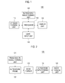
- FIG. 1 is a block diagram showing an arrangement of an image providing system 100 according to an embodiment of the present invention.
- the image providing system 100 comprises a computerized tomography (CT) image forming unit 110, an ultrasound image forming unit 120, a user input unit 130, a processor 140 and a display unit 150.
- CT computerized tomography
- the CT image forming unit 110 forms a 3-dimensional CT image for an object of interest inside a target object, which is composed of a plurality of 2-dimensional CT images.
- the CT image forming unit 110 may be configured to consecutively form 3-dimensional CT images I CT (t i ) (1 ⁇ i ⁇ K) at a predetermined interval during a respiratory cycle from inspiration to expiration.
- the ultrasound image forming unit 120 forms a 3-dimensional ultrasound image for the object of interest inside the target object.
- the ultrasound image forming unit 120 forms 3-dimensional ultrasound images I US (t j ) (1 ⁇ j ⁇ 2) at maximum inspiration and maximum expiration. Further, the ultrasound image forming unit 120 forms a 2-dimensional ultrasound image of the object of interest inside the target object.
- the 3-dimensional ultrasound images I US (t j ) (1 ⁇ j ⁇ 2) can be formed at either maximum inspiration or maximum expiration in other embodiments.
- the ultrasound image forming unit 120 forms the 3-dimensional ultrasound images I US (t j ) (1 ⁇ j ⁇ 2) at maximum inspiration and maximum expiration for the brevity of the description.
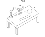
- FIG 2 is a block diagram showing an arrangement of the ultrasound image forming unit 120 according to an embodiment of the present invention.
- the ultrasound image forming unit 120 comprises a transmission signal forming unit 121, an ultrasound probe 122, a beam former 123, an ultrasound data forming unit 124 and an image forming unit 125.
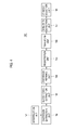
- the ultrasound image forming unit 120 may comprise an ultrasound probe holder 126 for fixing the ultrasound probe 122 in a specific location of the target object (P) as described in Figure 3 .
- the transmission signal forming unit 121 forms a first transmission signal to acquire each of the plurality of frames.
- the first transmission signal comprises at least one among the transmission signal to acquire each of the plurality of frames at maximum inspiration and the transmission signal to acquire each of the plurality of frames at maximum expiration.
- the transmission signal forming unit 121 forms a second transmission signal to acquire a frame.
- the frame may comprise a brightness mode (B-mode) image.
- the ultrasound probe 122 comprises multiple transducer elements (not shown).
- the ultrasound probe 122 may comprise a 3-dimensional probe. However, it should be noted herein that the ultrasound probe 122 may not be limited thereto.
- the ultrasound probe 122 converts the first transmission signal provided from the transmission signal forming unit 121 into an ultrasound signal, transmits the ultrasound signal to the target object and receives an ultrasound echo signal reflected by the target object to thereby form a first reception signal.
- the ultrasound probe 122 moves the transducer elements to the position set by the user.
- the ultrasound probe 122 then converts the second transmission signal provided from the transmission signal forming unit 121 into an ultrasound signal, transmits the ultrasound signal to the target object and receives an ultrasound echo signal reflected by the target object, thereby forming a second reception signal.
- the beam former 123 analog/digital converts the first reception signal to form a first digital signal.
- the beam former 123 forms a first receive-focused signal by receive-focusing the first digital signal considering the focal points and the locations of the transducer elements.
- the beam former 123 analog/digital converts the second reception signal to form a second digital signal.
- the beam former 123 forms a second receive-focused signal by receive-focusing the second digital signal considering the focal point and the location of the transducer elements.
- the ultrasound data forming unit 124 forms first ultrasound data using the first receive-focused signal when the first receive-focused signal is provided from the beam former 123.
- the ultrasound data forming unit 124 forms second ultrasound data using the second receive-focused signal when the second receive-focused signal is provided from the beam former 123.
- the ultrasound data forming unit 124 may perform signal processing, which is required to form ultrasound data (e.g., gain control, filtering, etc.) on the first or second receive-focused signal.
- the image forming unit 125 forms a 3-dimensional ultrasound image using the first ultrasound data when the first ultrasound data is provided from the ultrasound data forming unit 124.
- the 3-dimensional ultrasound image comprises at least one of the 3-dimensional ultrasound image at maximum inspiration (I US (t 1 )) and the 3-dimensional ultrasound image at maximum expiration (I US (t 2 )).
- the image forming unit 125 forms the 2-dimensional ultrasound image using the second ultrasound data when the second ultrasound data is provided from the ultrasound data forming unit 124.
- the user input unit 130 receives input information from the user.
- the input information comprises reference plane setting information that sets a reference plane in the 3-dimensional ultrasound image across which the 2-dimensional ultrasound image will be obtained, diaphragm area setting information which sets diaphragm areas on the 3-dimensional CT images I CT (t i ) (1 ⁇ i ⁇ K) and blood vessel area setting information which sets blood vessels area on the 3-dimensional CT images I CT (t i ) (1 ⁇ i ⁇ K).
- the reference plane setting information may comprise reference plane setting information that sets one rotation angle within the rotation angle range in which the transducer element of the ultrasound probe 122 (i.e., 3-dimensional probe) can swing (i.e., -35° to 35°).
- the ultrasound image forming unit 120 can form the 2-dimensional ultrasound image corresponding to the reference plane setting information.
- the user input unit 130 may be implemented with control panel which comprises dial button and the like, mouse, keyboard, etc.
- the processor 140 performs image registration between 3-dimensional CT image and 3-dimensional ultrasound image to obtain a transform function between the 3-dimensional CT image and the 3-dimensional ultrasound image (i.e., location of ultrasound probe 122 T probe ).
- a transform function between the 3-dimensional CT image and the 3-dimensional ultrasound image (i.e., location of ultrasound probe 122 T probe ).
- the 3-dimensional ultrasound images I US (t j ) (1 ⁇ j ⁇ 2) comprise the 3-dimensional ultrasound image at maximum inspiration (I US (t 1 )) and the 3-dimensional ultrasound image at maximum expiration (I US (t 2 )).
- the processor 140 detects a 2-dimensional CT image corresponding to the 2-dimensional ultrasound image using the transform function.
- FIG. 4 is a block diagram showing an arrangement of the processor 140 according to an embodiment of the present invention.
- the processor 140 comprises an interpolation unit 141, a diaphragm extraction unit 142, a blood vessel extraction unit 143, a diaphragm refining unit 144, a registration unit 145, a transform unit 146, a similarity detection unit 147 and a CT image selection unit 148.
- the interpolation unit 141 interpolates the 3-dimensional CT image I CT (t i ) and the 3-dimensional CT image I CT (t i+1 ) provided from the CT image forming unit 110 to form at least one 3-dimensional CT image between the 3-dimensional CT image I CT (t i ) and the 3-dimensional CT image I CT (t i+1 ).
- the interpolation unit 141 performs interpolation between the 3-dimensional CT images I CT (t i ) (1 ⁇ i ⁇ K) provided from the CT image forming unit 110 to acquire N 3-dimensional CT images I CT (t i ) (1 ⁇ i ⁇ N).
- the diaphragm extraction unit 142 extracts a diaphragm from each of the 3-dimensional CT images I CT (t i ) (1 ⁇ i ⁇ N) provided from the interpolation unit 141. In addition, the diaphragm extraction unit 142 extracts a diaphragm from the 3-dimensional ultrasound images I US (t j ) (1 ⁇ j ⁇ 2) provided from the ultrasound image forming unit 120.
- the diaphragm extraction unit 142 perform a flatness test on the 3-dimensional CT images I CT (t i ) (1 ⁇ i ⁇ N) and the 3-dimensional ultrasound images I US (t j ) (1 ⁇ j ⁇ 2) based on a Hessian matrix to extract the diaphragm. That is, the diaphragm extraction unit 142 extracts an area in which the change in the voxel intensity perpendicular to the surface is larger than the change in the voxel intensity parallel to the surface as the diaphragm, considering that the diaphragm is a curved surface on the 3-dimensional CT image and the 3-dimensional ultrasound image.
- Figure 5 shows Hessian matrix eigen values ⁇ 1 , ⁇ 2 , ⁇ 3 according to directions.
- the diaphragm extraction unit 142 selects voxels having flatness higher than a reference value to extract the diaphragms from the 3-dimensional CT images I CT (t i ) (1 ⁇ i ⁇ N) and the 3-dimensional ultrasound images I US (t j ) (1 ⁇ j ⁇ 2).
- the flatness ⁇ (v) is defined as below.
- ⁇ 1 ⁇ 1 - ⁇ 1 ⁇ ⁇ 3 ⁇ 2
- ⁇ 2 ⁇ 1 - ⁇ 2 ⁇ ⁇ 3 ⁇ 2
- ⁇ 3 ⁇ ⁇ i ⁇ ⁇ i ⁇ 2
- ⁇ 1 (v), ⁇ 2 (v) and ⁇ 3 (v) represent the Hessian matrix eigen values according to the location of the voxel.
- the flatness ⁇ (v) is normalized to have a value between 0 and 1.
- the diaphragm extraction unit 142 forms a flatness map using the flatness obtained from the equations (1) and (2), and selects voxels having relatively higher flatness. In this embodiment, the diaphragm extraction unit 142 selects voxels having flatness of 0.1 or more.
- the diaphragm extraction unit 142 removes small clutters by performing morphological opening for the selected voxels (morphological filtering).
- the morphological opening means performing erosion and dilation sequentially.
- the diaphragm extraction unit 142 removes edge of the area in which the voxel values exist morphologically as many as the predetermined number of voxels to contract the edge (erosion), and then expands it as many as the predetermined number of the voxels (dilation). In an embodiment of the present invention, the diaphragm extraction unit 142 contracts and expands the edge by 1 voxel.
- the diaphragm is the largest surface in the 3-dimensional CT image and the 3-dimensional ultrasound image
- the largest surface among candidate surfaces obtained by the intensity-based connected component analysis (CCA) for the voxels may be selected as the diaphragm.
- the voxel-based CCA is one of the methods of grouping regions in which voxel values exist.
- the diaphragm extraction unit 142 computes the number of voxels connected to each of the voxels through a connectivity test by referring to values of voxels neighboring to the corresponding voxel (e.g., 26 voxels), and selects the voxels of which the number of connected voxels are greater than the predetermined number as candidate groups.
- the diaphragm extraction unit 142 extracts the candidate group having the largest number of connected voxels as the diaphragm. Thereafter, the diaphragm extraction unit 142 can smoothen the surface of the diaphragm.
- the diaphragm extraction unit 142 extracts the diaphragm by performing the foregoing process on the 3-dimensional ultrasound images I US (t j ) (1 ⁇ j ⁇ 2).
- the diaphragm extraction unit 142 extracts the diaphragm from the 3-dimensional CT images I CT (t i ) (1 ⁇ i ⁇ N) based on the input information (i.e., diaphragm area setting information). More particularly, since the 3-dimensional CT image has more distinct boundaries of liver than typical ultrasound images, the diaphragm extraction unit 142 may extract the diaphragm using methods such as a commercial program for extracting liver area or a seeded region growing segmentation method.
- the blood vessel extraction unit 143 extracts blood vessels from the 3-dimensional CT images I CT (t i ) (1 ⁇ i ⁇ N). In addition, the blood vessel extraction unit 143 extracts blood vessels from the 3-dimensional ultrasound images I US (t j ) (1 ⁇ j ⁇ 2).
- the blood vessel extraction unit 143 can perform a blood vessel extraction from the 3-dimensional CT images I CT (t i ) (1 ⁇ i ⁇ N) and the 3-dimensional ultrasound images I US (t j ) (1 ⁇ j ⁇ 2) through masking, blood vessel segmentation and classification.
- the blood vessel extraction unit 143 sets the region of interest (ROI) masking on the 3-dimensional CT images I CT (t i ) (1 ⁇ i ⁇ N) and the 3-dimensional ultrasound images I US (t j ) (1 ⁇ j ⁇ 2) by modeling the diaphragms as a polynomial curved surface.
- the blood vessel extraction unit 143 may remove the portions of the modeled polynomial curved surface lower than the diaphragm using the ROI masking on the 3-dimensional CT images I CT (t i ) (1 ⁇ i ⁇ N) and the 3-dimensional ultrasound images I US (t j ) (1 ⁇ j ⁇ 2).
- the blood vessel extraction unit 143 may perform modeling the diaphragm as the polynomial curved surface using the least means square (LMS). However, if all of the lower portions of the modeled polynomial curved surface are eliminated, then meaningful blood vessel information may be lost at some regions due to errors of the polynomial curved surface. To avoid losing the blood vessel information, the blood vessel extraction unit 143 applies a marginal distance of about 10 voxels from the bottom of the ROI mask and then eliminates the lower portion.
- LMS least means square
- the blood vessel extraction unit 143 segments blood vessel regions and non-vessel regions. To exclude the non-vessel regions with high intensity such as the diaphragm and the vessel walls, the blood vessel extraction unit 143 estimates the low intensity bound having less intensity than a reference bound value in the ROI masked image, and removes voxels having higher intensity than the reference bound value. The blood vessel extraction unit 143 binarizes the remaining regions by applying an adaptive threshold scheme. The binarized regions become blood vessel candidates.
- the blood vessel extraction unit 143 removes non-vessel-type clutters to classify real blood vessels from the blood vessel candidates.
- the process of blood vessel classification includes a size test for removing small clutters, a structure-based vessel test that removes non-vessel type by evaluating the goodness of fit (GOF) to a cylindrical tube (i.e., initial vessel test), gradient magnitude analysis and a final vessel test for perfectly removing the clutters.
- An initial threshold C initial is marginally set such that all blood vessels are included even if some clutters are not removed in the structure-based vessel test. In this embodiment, the initial threshold is set to 0.6.
- the blood vessel extraction unit 143 considers the variation of voxel values (i.e., gradient magnitude), and precisely removes all of the clutters formed by shading artifacts having low gradient magnitudes to extract the blood vessel.
- a threshold of the final vessel test is set to 0.4.
- the blood vessel extraction unit 143 extracts blood vessels by performing the process described above on the 3-dimensional ultrasound images I US (t j ) (1 ⁇ j ⁇ 2). Further, the blood vessel extraction unit 143 extracts blood vessel from the 3-dimensional CT images I CT (t i ) (1 ⁇ i ⁇ N) based on the input information (i.e., blood vessel area setting information) provided from the user input unit. More specifically, using the characteristic that blood vessels have brighter pixel value than the tissues in the liver area in the 3-dimensional CT angiography image, the blood vessel extraction unit 143 set a value of 255 only to the pixels having the value between a first threshold (T1) and a second threshold (T2), and set a value of 0 to the rest of the pixels.
- T1 first threshold
- T2 second threshold
- the blood vessel extraction unit 143 uses the connectivity of the blood vessels.
- the blood vessels within the liver area are composed of the portal vein and hepatic vein.
- the blood vessel extraction unit 143 extracts only the blood vessels by entering two specific location corresponding to each of the blood vessels as seed points and performing the seeded region growing method using the seed points as starting points.
- the diaphragm refining unit 144 refines the diaphragms on the 3-dimensional ultrasound images I US (t j ) (1 ⁇ j ⁇ 2) by using the blood vessels extracted from the blood vessel extraction unit 143. More specifically, the diaphragm refining unit 144 removes the clutters by performing refinement of the diaphragm using the blood vessels extracted from the blood vessel extraction unit 143.
- the clutters are typically located near the vessel walls in the extracted diaphragm.
- the inferior vena cava (IVC) is connected to the diaphragm and causes clutters.
- the diaphragm refining unit 144 enhances the diaphragm by removing the clutters.
- the diaphragm refining unit 144 extracts the blood vessel regions from the 3-dimensional ultrasound images I US (t j ) (1 ⁇ j ⁇ 2), dilates the extracted blood vessel regions, and removes the blood vessels through which the blood is flowing to thereby estimate the vessel walls.
- the diaphragm refining unit 144 extracts the diaphragm by applying CCA and the size text once more.
- the registration unit 145 sets sample points on anatomical features (i.e., blood vessel region and diaphragm region) for the 3-dimensional CT images I CT (t i ) (1 ⁇ i ⁇ N) and the 3-dimensional ultrasound images I US (t j ) (1 ⁇ j ⁇ 2).
- the registration unit 145 then performs image registration between the 3-dimensional CT images I CT (t i ) (1 ⁇ i ⁇ N) and the 3-dimensional ultrasound images I US (t j ) (1 ⁇ j ⁇ 2) using the set sample points to obtain the transform function T probe between the 3-dimensional ultrasound image and the 3-dimensional CT image.
- the transform function T probe may be represented by a matrix.
- the transform function T probe can be obtained by the equation (3).
- the registration unit 145 defines the dist value with a least error between the 3-dimensional ultrasound image at maximum inspiration (I US (t 1 )) and the 3-dimensional CT image (I CT (t i )) as a first error, and defines the dist value with a least error between the 3-dimensional ultrasound image at maximum expiration (I US (t 2 )) and the 3-dimensional CT image (I CT (t i )) as a second error. Then, the registration unit 145 obtains the transform function T probe by calculating X that makes the sum of the first error and the second error least.
- the transform unit 146 generates the transform function T for transforming the 3-dimensional CT images I CT (t i ) (1 ⁇ i ⁇ N) based on the input information provided from the user input unit 130 and the transform function T probe provided from the registration unit 145. Then, the transform unit 146 acquires the 2-dimensional CT images I 2CT (t i ) (1 ⁇ i ⁇ N) by applying the generated transform function T to the 3-dimensional CT images I CT (t i ) (1 ⁇ i ⁇ N).
- the similarity detection unit 147 detects the similarities between the 2-dimensional ultrasound image and the 2-dimensional CT images I 2CT (t i ) (1 ⁇ i ⁇ N).
- the similarities can be detected using cross correlation, mutual information, sum of squared intensity difference (SSID) and the like.
- the CT image selection unit 148 selects a 2-dimensional CT image I 2CT (t i ) that has the largest similarity by comparing the similarities detected at the similarity detection unit 147.
- the display unit 150 displays the 2-dimensional ultrasound image provided from the ultrasound image forming unit 120 and the 2-dimensional CT image provided from the processor 140.
- the 2-dimensional ultrasound image and the 2-dimensional CT image can be displayed in an overlapping manner.
- the 2-dimensional ultrasound image and the 2-dimensional CT image can be displayed top and bottom or left and right on the same screen.
- the CT image forming unit 110 forms 3-dimensional CT images I CT (t i ) (1 ⁇ i ⁇ K) at a predetermined interval during a respiratory cycle from inspiration to expiration (S102).
- the interpolation unit 141 of the processor 140 performs interpolation between the 3-dimensional CT images I CT (t i ) (1 ⁇ i ⁇ K) provided from the CT image forming unit 110 to acquire 3-dimensional CT images I CT (t i ) (1 ⁇ i ⁇ N) (S104).
- the ultrasound image forming unit 120 forms the 3-dimensional ultrasound image of the object of interest inside the target object at maximum inspiration (I US (t 1 )) and the 3-dimensional ultrasound image of the object of interest inside the target object at maximum expiration (I US (t 2 )) (S108).
- the processor 140 extracts anatomical features (e.g., blood vessel and diaphragm) from the 3-dimensional CT images I CT (t i ) (1 ⁇ i ⁇ N) and the 3-dimensional ultrasound images I US (t j ) (1 ⁇ j ⁇ 2) (S110).
- anatomical features e.g., blood vessel and diaphragm
- the registration unit 145 of the processor 140 sets sample points on anatomical features (i.e., blood vessel region and diaphragm region) for the 3-dimensional CT images I CT (t i ) (1 ⁇ i ⁇ N) and the 3-dimensional ultrasound images I US (t j ) (1 ⁇ j ⁇ 2).
- the registration unit 145 then performs image registration between the 3-dimensional CT images I CT (t i ) (1 ⁇ i ⁇ N) and the 3-dimensional ultrasound images I US (t j ) (1 ⁇ j ⁇ 2) using the set sample points to obtain the transform function T probe between the 3-dimensional ultrasound image and the 3-dimensional CT image (S 112).
- the ultrasound image forming unit 120 Upon receiving the input information (i.e., reference plane setting information) through the user input unit 130 (S 114), the ultrasound image forming unit 120 forms the 2-dimensional ultrasound image of the section corresponding to the input information (S116).
- the transform unit 146 of the processor 140 generates transform function T for transforming the 3-dimensional CT images I CT (t i ) (1 ⁇ i ⁇ N) based on the input information (i.e., reference plane setting information) provided from the user input unit 130 and the transform function T probe provided from the registration unit 145. Then, the transform unit 146 acquires the 2-dimensional CT images I 2CT (t i ) (1 ⁇ i ⁇ N) by applying the generated transform function T to the 3-dimensional CT images I CT (t i ) (1 ⁇ i ⁇ N) (S118).
- the transform unit 146 obtains a transform function T plane representing the location of the 2-dimensional ultrasound image on the 3-dimensional ultrasound images I US (t j ) (1 ⁇ j ⁇ N) (i.e., location of ultrasound probe 122 for 2-dimensional ultrasound image) based on the input information provided from the user input unit 130.
- the transform function T plane can be represented as a matrix.
- the transform unit 146 generates a transform function T for transforming the 3-dimensional CT images I CT (t i ) (1 ⁇ i ⁇ N) using the transform function T probe and the transform function T plane .
- the transform unit 146 can generate the transform function T by multiplying the transform function T probe by the transform function T plane.
- the transform unit 146 acquires the 2-dimensional CT images I 2CT (t i ) (1 ⁇ i ⁇ N) by applying the transform function T to each of the 3-dimensional CT images I CT (t i ) (1 ⁇ i ⁇ N).
- the similarity detection unit 147 of the processor 140 detects the similarities between the 2-dimensional ultrasound image provided from the ultrasound image forming unit 120 and the 2-dimensional CT images I 2CT (t i ) (1 ⁇ i ⁇ N) provided from the transform unit 146 (S120).
- the CT image selection unit 148 selects a 2-dimensional CT image I 2CT (t i ) that has the largest similarity by comparing the similarities detected at the similarity detection unit 147 (S122).
- the display unit 150 displays the 2-dimensional ultrasound image provided from the ultrasound image forming unit 120 and the 2-dimensional CT image provided from the CT image selection unit 148 (S124).
Landscapes
- Health & Medical Sciences (AREA)
- Life Sciences & Earth Sciences (AREA)
- Engineering & Computer Science (AREA)
- Physics & Mathematics (AREA)
- Medical Informatics (AREA)
- Heart & Thoracic Surgery (AREA)
- Molecular Biology (AREA)
- Biophysics (AREA)
- Nuclear Medicine, Radiotherapy & Molecular Imaging (AREA)
- Pathology (AREA)
- Radiology & Medical Imaging (AREA)
- Biomedical Technology (AREA)
- Veterinary Medicine (AREA)
- Public Health (AREA)
- General Health & Medical Sciences (AREA)
- Surgery (AREA)
- Animal Behavior & Ethology (AREA)
- Theoretical Computer Science (AREA)
- Computer Vision & Pattern Recognition (AREA)
- General Physics & Mathematics (AREA)
- High Energy & Nuclear Physics (AREA)
- Optics & Photonics (AREA)
- Ultra Sonic Daignosis Equipment (AREA)
- Apparatus For Radiation Diagnosis (AREA)
- Image Generation (AREA)
Applications Claiming Priority (1)
| Application Number | Priority Date | Filing Date | Title |
|---|---|---|---|
| KR1020090070981A KR101121396B1 (ko) | 2009-07-31 | 2009-07-31 | 2차원 초음파 영상에 대응하는 2차원 ct 영상을 제공하는 시스템 및 방법 |
Publications (1)
| Publication Number | Publication Date |
|---|---|
| EP2293245A1 true EP2293245A1 (en) | 2011-03-09 |
Family
ID=42735491
Family Applications (1)
| Application Number | Title | Priority Date | Filing Date |
|---|---|---|---|
| EP10170226A Ceased EP2293245A1 (en) | 2009-07-31 | 2010-07-21 | Providing a 2-dimensional CT image corresponding to a 2-dimensional ultrasound image |
Country Status (4)
| Country | Link |
|---|---|
| US (1) | US20110028843A1 (ko) |
| EP (1) | EP2293245A1 (ko) |
| JP (1) | JP5498299B2 (ko) |
| KR (1) | KR101121396B1 (ko) |
Families Citing this family (21)
| Publication number | Priority date | Publication date | Assignee | Title |
|---|---|---|---|---|
| EP2130497A1 (en) * | 2008-06-05 | 2009-12-09 | Medison Co., Ltd. | Anatomical feature extraction from an ultrasound liver image |
| US20120253170A1 (en) * | 2011-03-29 | 2012-10-04 | Samsung Electronics Co., Ltd. | Method and apparatus for generating medical image of body organ by using 3-d model |
| TWI446897B (zh) | 2011-08-19 | 2014-08-01 | Ind Tech Res Inst | 超音波影像對齊裝置及其方法 |
| KR101932721B1 (ko) | 2012-09-07 | 2018-12-26 | 삼성전자주식회사 | 의료 영상들의 정합 방법 및 장치 |
| KR102001219B1 (ko) | 2012-11-26 | 2019-07-17 | 삼성전자주식회사 | 의료 영상들의 정합 방법 및 장치 |
| US9922447B2 (en) * | 2013-04-30 | 2018-03-20 | Mantis Vision Ltd. | 3D registration of a plurality of 3D models |
| US9230331B2 (en) * | 2013-10-21 | 2016-01-05 | Samsung Electronics Co., Ltd. | Systems and methods for registration of ultrasound and CT images |
| KR102233427B1 (ko) | 2014-04-14 | 2021-03-29 | 삼성전자주식회사 | 의료 영상 정합 방법 및 장치 |
| US8958623B1 (en) * | 2014-04-29 | 2015-02-17 | Heartflow, Inc. | Systems and methods for correction of artificial deformation in anatomic modeling |
| KR102250086B1 (ko) | 2014-05-16 | 2021-05-10 | 삼성전자주식회사 | 의료 영상 정합 방법, 이를 포함하는 장치 및 컴퓨터 기록 매체 |
| US10966688B2 (en) * | 2014-08-26 | 2021-04-06 | Rational Surgical Solutions, Llc | Image registration for CT or MR imagery and ultrasound imagery using mobile device |
| CN106687048A (zh) * | 2014-09-08 | 2017-05-17 | 皇家飞利浦有限公司 | 医学成像装置 |
| US10675006B2 (en) * | 2015-05-15 | 2020-06-09 | Siemens Medical Solutions Usa, Inc. | Registration for multi-modality medical imaging fusion with narrow field of view |
| KR101927298B1 (ko) * | 2015-06-22 | 2019-03-08 | 연세대학교 산학협력단 | 혈관 조영 영상에서 자동으로 혈관을 영역화하는 기법 |
| JP6865755B2 (ja) | 2015-12-22 | 2021-04-28 | コーニンクレッカ フィリップス エヌ ヴェKoninklijke Philips N.V. | 被験者のボリュームを検査する医用撮像装置及び医用撮像方法 |
| KR101900679B1 (ko) * | 2016-12-02 | 2018-09-20 | 숭실대학교산학협력단 | 혈관 특징 정보를 기반으로 하는 삼차원 심혈관 정합 방법, 이를 수행하기 위한 기록 매체 및 장치 |
| EP3508132A1 (en) | 2018-01-04 | 2019-07-10 | Koninklijke Philips N.V. | Ultrasound system and method for correcting motion-induced misalignment in image fusion |
| KR102099415B1 (ko) * | 2018-02-23 | 2020-04-09 | 서울대학교산학협력단 | Ct 데이터와 광학 데이터의 정합성능 향상 방법 및 그 장치 |
| KR102427573B1 (ko) * | 2019-09-09 | 2022-07-29 | 하이윈 테크놀로지스 코포레이션 | 의료 영상 등록 방법 |
| CN113041515A (zh) * | 2021-03-25 | 2021-06-29 | 中国科学院近代物理研究所 | 三维图像引导运动器官定位方法、系统及存储介质 |
| KR102444581B1 (ko) * | 2021-10-07 | 2022-09-19 | 주식회사 피맥스 | 흉부 영상으로부터 횡격막을 검출하는 방법 및 이를 위한 장치 |
Citations (3)
| Publication number | Priority date | Publication date | Assignee | Title |
|---|---|---|---|---|
| US20070167806A1 (en) * | 2005-11-28 | 2007-07-19 | Koninklijke Philips Electronics N.V. | Multi-modality imaging and treatment |
| US20080212858A1 (en) * | 2007-03-02 | 2008-09-04 | Siemens Aktiengesellschaft | Method for image registration processes and X-ray angiography system |
| US20090097778A1 (en) * | 2007-10-11 | 2009-04-16 | General Electric Company | Enhanced system and method for volume based registration |
Family Cites Families (12)
| Publication number | Priority date | Publication date | Assignee | Title |
|---|---|---|---|---|
| US5640956A (en) * | 1995-06-07 | 1997-06-24 | Neovision Corporation | Methods and apparatus for correlating ultrasonic image data and radiographic image data |
| JP3834365B2 (ja) * | 1996-10-16 | 2006-10-18 | アロカ株式会社 | 超音波診断装置 |
| US7117026B2 (en) * | 2002-06-12 | 2006-10-03 | Koninklijke Philips Electronics N.V. | Physiological model based non-rigid image registration |
| JP2004174220A (ja) * | 2002-10-01 | 2004-06-24 | Japan Science & Technology Agency | 画像処理装置、画像処理方法、及び当該画像処理方法をコンピュータに実行させるプログラムを格納する記録媒体 |
| WO2004096018A2 (en) * | 2003-04-28 | 2004-11-11 | Vanderbilt University | Apparatus and methods of optimal placement of deep brain stimulator |
| US7996060B2 (en) * | 2006-10-09 | 2011-08-09 | Biosense Webster, Inc. | Apparatus, method, and computer software product for registration of images of an organ using anatomical features outside the organ |
| DE102007009017B3 (de) * | 2007-02-23 | 2008-09-25 | Siemens Ag | Anordnung zur Unterstützung eines perkutanen Eingriffs |
| KR101411639B1 (ko) * | 2007-09-11 | 2014-06-24 | 삼성전기주식회사 | 영상 정합 방법 및 장치 |
| JP2009106530A (ja) * | 2007-10-30 | 2009-05-21 | Toshiba Corp | 医用画像処理装置、医用画像処理方法、及び医用画像診断装置 |
| JP5835680B2 (ja) * | 2007-11-05 | 2015-12-24 | 株式会社東芝 | 画像位置合わせ装置 |
| US8111892B2 (en) * | 2008-06-04 | 2012-02-07 | Medison Co., Ltd. | Registration of CT image onto ultrasound images |
| US8724874B2 (en) * | 2009-05-12 | 2014-05-13 | Siemens Aktiengesellschaft | Fusion of 3D volumes with CT reconstruction |
-
2009
- 2009-07-31 KR KR1020090070981A patent/KR101121396B1/ko active IP Right Grant
-
2010
- 2010-07-21 EP EP10170226A patent/EP2293245A1/en not_active Ceased
- 2010-07-26 JP JP2010167490A patent/JP5498299B2/ja not_active Expired - Fee Related
- 2010-07-29 US US12/846,528 patent/US20110028843A1/en not_active Abandoned
Patent Citations (3)
| Publication number | Priority date | Publication date | Assignee | Title |
|---|---|---|---|---|
| US20070167806A1 (en) * | 2005-11-28 | 2007-07-19 | Koninklijke Philips Electronics N.V. | Multi-modality imaging and treatment |
| US20080212858A1 (en) * | 2007-03-02 | 2008-09-04 | Siemens Aktiengesellschaft | Method for image registration processes and X-ray angiography system |
| US20090097778A1 (en) * | 2007-10-11 | 2009-04-16 | General Electric Company | Enhanced system and method for volume based registration |
Non-Patent Citations (6)
| Title |
|---|
| DONG-GOO KANG ET AL: "Registration of CT-ultrasound images of the liver based on efficient vessel-filtering and automatic initial transform prediction", INT. J. CARS., VOL. 1, SUPPLEMENT 1,, 1 June 2006 (2006-06-01), pages 54 - 57, XP055198305 * |
| EADIE L H ET AL: "A real time pointer to a pre-operative surgical planning index block of ultrasound images for image guided surgery", PROCEEDINGS OF SPIE - THE INTERNATIONAL SOCIETY FOR OPTICAL ENGINEERING - VISUALIZATION AND DATA ANALYSIS 2004 2004 SPIE US, vol. 5295, 19 January 2004 (2004-01-19), pages 14 - 23, XP040254280, DOI: 10.1117/12.526863 * |
| JI S ET AL: "Coregistered volumetric true 3D ultrasonography in image-guided neurosurgery", PROGRESS IN BIOMEDICAL OPTICS AND IMAGING - PROCEEDINGS OF SPIE - MEDICAL IMAGING 2008 - VISUALIZATION, IMAGE-GUIDED PROCEDURES, AND MODELING 2008 SPIE US, vol. 6918, 17 February 2008 (2008-02-17), XP040435164, DOI: 10.1117/12.770382 * |
| LEE D ET AL: "Sensorless and real-time registration between 2D ultrasound and preoperative images of the liver", 2010 7TH IEEE INTERNATIONAL SYMPOSIUM ON BIOMEDICAL IMAGING: FROM NANO TO MACRO, ISBI 2010 - PROCEEDINGS - 2010 7TH IEEE INTERNATIONAL SYMPOSIUM ON BIOMEDICAL IMAGING: FROM NANO TO MACRO, ISBI 2010 - PROCEEDINGS 2010 IEEE COMPUTER SOCIETY USA, 14 April 2010 (2010-04-14), pages 388 - 391, XP002602573, DOI: 10.1109/ISBI.2010.5490329 * |
| W. H. NAM, D. -G. KANG, D. LEE, AND J. B. RA: "Anatomical feature extraction in 3D B-mode ultrasound liver images for CT-ultrasound image registration", PROC. CARS 2008, vol. 3, Supplement 1, June 2008 (2008-06-01), pages 401 - 402, XP002602575 * |
| XISHI HUANG ET AL: "Dynamic 2D Ultrasound and 3D CT Image Registration of the Beating Heart", IEEE TRANSACTIONS ON MEDICAL IMAGING, IEEE SERVICE CENTER, PISCATAWAY, NJ, US, vol. 28, no. 8, 6 January 2009 (2009-01-06), pages 1179 - 1189, XP011249697, ISSN: 0278-0062 * |
Also Published As
| Publication number | Publication date |
|---|---|
| KR20110013026A (ko) | 2011-02-09 |
| JP5498299B2 (ja) | 2014-05-21 |
| JP2011031040A (ja) | 2011-02-17 |
| KR101121396B1 (ko) | 2012-03-05 |
| US20110028843A1 (en) | 2011-02-03 |
Similar Documents
| Publication | Publication Date | Title |
|---|---|---|
| EP2293245A1 (en) | Providing a 2-dimensional CT image corresponding to a 2-dimensional ultrasound image | |
| KR101121286B1 (ko) | 센서의 교정을 수행하는 초음파 시스템 및 방법 | |
| KR101121353B1 (ko) | 2차원 초음파 영상에 대응하는 2차원 ct 영상을 제공하는 시스템 및 방법 | |
| US10679347B2 (en) | Systems and methods for ultrasound imaging | |
| KR101017611B1 (ko) | 초음파 - ct 영상 정합을 위한 3차원 초음파 간 영상의 해부학적 특징을 추출하는 시스템 및 방법 | |
| US9536318B2 (en) | Image processing device and method for detecting line structures in an image data set | |
| US20060074312A1 (en) | Medical diagnostic ultrasound signal extraction | |
| JP4709290B2 (ja) | 画像処理装置および方法並びにプログラム | |
| US20170199261A1 (en) | Method for assessing and improving data quality in fine structure analysis data | |
| CN112826535A (zh) | 一种超声成像中自动定位血管的方法和装置及设备 |
Legal Events
| Date | Code | Title | Description |
|---|---|---|---|
| PUAI | Public reference made under article 153(3) epc to a published international application that has entered the european phase |
Free format text: ORIGINAL CODE: 0009012 |
|
| AK | Designated contracting states |
Kind code of ref document: A1 Designated state(s): AL AT BE BG CH CY CZ DE DK EE ES FI FR GB GR HR HU IE IS IT LI LT LU LV MC MK MT NL NO PL PT RO SE SI SK SM TR |
|
| AX | Request for extension of the european patent |
Extension state: BA ME RS |
|
| 17P | Request for examination filed |
Effective date: 20110830 |
|
| 17Q | First examination report despatched |
Effective date: 20120817 |
|
| STAA | Information on the status of an ep patent application or granted ep patent |
Free format text: STATUS: THE APPLICATION HAS BEEN REFUSED |
|
| 18R | Application refused |
Effective date: 20160505 |