EP2292939A2 - Concrete screw - Google Patents
Concrete screw Download PDFInfo
- Publication number
- EP2292939A2 EP2292939A2 EP10174710A EP10174710A EP2292939A2 EP 2292939 A2 EP2292939 A2 EP 2292939A2 EP 10174710 A EP10174710 A EP 10174710A EP 10174710 A EP10174710 A EP 10174710A EP 2292939 A2 EP2292939 A2 EP 2292939A2
- Authority
- EP
- European Patent Office
- Prior art keywords
- screw
- thread
- concrete
- section
- einformbereich
- Prior art date
- Legal status (The legal status is an assumption and is not a legal conclusion. Google has not performed a legal analysis and makes no representation as to the accuracy of the status listed.)
- Withdrawn
Links
- 238000000465 moulding Methods 0.000 claims abstract description 10
- 238000003780 insertion Methods 0.000 claims 2
- 230000037431 insertion Effects 0.000 claims 2
- 238000011161 development Methods 0.000 description 7
- 230000018109 developmental process Effects 0.000 description 7
- 230000015572 biosynthetic process Effects 0.000 description 3
- 230000003247 decreasing effect Effects 0.000 description 3
- 238000005096 rolling process Methods 0.000 description 2
- 230000001419 dependent effect Effects 0.000 description 1
- 235000013312 flour Nutrition 0.000 description 1
- 238000001746 injection moulding Methods 0.000 description 1
- 239000000463 material Substances 0.000 description 1
- 239000011435 rock Substances 0.000 description 1
- 230000036346 tooth eruption Effects 0.000 description 1
- 230000007704 transition Effects 0.000 description 1
Images


Classifications
-
- F—MECHANICAL ENGINEERING; LIGHTING; HEATING; WEAPONS; BLASTING
- F16—ENGINEERING ELEMENTS AND UNITS; GENERAL MEASURES FOR PRODUCING AND MAINTAINING EFFECTIVE FUNCTIONING OF MACHINES OR INSTALLATIONS; THERMAL INSULATION IN GENERAL
- F16B—DEVICES FOR FASTENING OR SECURING CONSTRUCTIONAL ELEMENTS OR MACHINE PARTS TOGETHER, e.g. NAILS, BOLTS, CIRCLIPS, CLAMPS, CLIPS OR WEDGES; JOINTS OR JOINTING
- F16B25/00—Screws that cut thread in the body into which they are screwed, e.g. wood screws
- F16B25/001—Screws that cut thread in the body into which they are screwed, e.g. wood screws characterised by the material of the body into which the screw is screwed
- F16B25/0026—Screws that cut thread in the body into which they are screwed, e.g. wood screws characterised by the material of the body into which the screw is screwed the material being a hard non-organic material, e.g. stone, concrete or drywall
-
- F—MECHANICAL ENGINEERING; LIGHTING; HEATING; WEAPONS; BLASTING
- F16—ENGINEERING ELEMENTS AND UNITS; GENERAL MEASURES FOR PRODUCING AND MAINTAINING EFFECTIVE FUNCTIONING OF MACHINES OR INSTALLATIONS; THERMAL INSULATION IN GENERAL
- F16B—DEVICES FOR FASTENING OR SECURING CONSTRUCTIONAL ELEMENTS OR MACHINE PARTS TOGETHER, e.g. NAILS, BOLTS, CIRCLIPS, CLAMPS, CLIPS OR WEDGES; JOINTS OR JOINTING
- F16B25/00—Screws that cut thread in the body into which they are screwed, e.g. wood screws
- F16B25/0036—Screws that cut thread in the body into which they are screwed, e.g. wood screws characterised by geometric details of the screw
- F16B25/0042—Screws that cut thread in the body into which they are screwed, e.g. wood screws characterised by geometric details of the screw characterised by the geometry of the thread, the thread being a ridge wrapped around the shaft of the screw
- F16B25/0052—Screws that cut thread in the body into which they are screwed, e.g. wood screws characterised by geometric details of the screw characterised by the geometry of the thread, the thread being a ridge wrapped around the shaft of the screw the ridge having indentations, notches or the like in order to improve the cutting behaviour
-
- F—MECHANICAL ENGINEERING; LIGHTING; HEATING; WEAPONS; BLASTING
- F16—ENGINEERING ELEMENTS AND UNITS; GENERAL MEASURES FOR PRODUCING AND MAINTAINING EFFECTIVE FUNCTIONING OF MACHINES OR INSTALLATIONS; THERMAL INSULATION IN GENERAL
- F16B—DEVICES FOR FASTENING OR SECURING CONSTRUCTIONAL ELEMENTS OR MACHINE PARTS TOGETHER, e.g. NAILS, BOLTS, CIRCLIPS, CLAMPS, CLIPS OR WEDGES; JOINTS OR JOINTING
- F16B25/00—Screws that cut thread in the body into which they are screwed, e.g. wood screws
- F16B25/0036—Screws that cut thread in the body into which they are screwed, e.g. wood screws characterised by geometric details of the screw
- F16B25/0078—Screws that cut thread in the body into which they are screwed, e.g. wood screws characterised by geometric details of the screw with a shaft of non-circular cross-section or other special geometric features of the shaft
Definitions
- the invention relates to a screw for screwing in hard ground, such as concrete, masonry or the like.
- this type of screw is referred to as a concrete screw.
- the known screws of this type have a shank cross section which is circular, and the thread edge of the screw thread is, apart from notches to facilitate the discharge of rock flour or dissolved concrete, on a helical line which lies in the circumferential surface of a circular cylinder.
- the invention is based on the object, a screw in such a way that it can well mold the thread in the predrilled hole and that the risk of breaking out of the concrete is reduced.
- the invention proposes a screw with the features mentioned in claim 1. Further developments of the invention are the subject of dependent claims.
- the invention utilizes the recognition that the front portion of the screw is more involved in the formation of the thread than the later portion, and makes this front molding portion in a manner that facilitates molding of the thread without the risk of breaking the masonry or concrete ,
- it uses a geometry in which the thread edge of the thread has a decreasing from the longitudinal axis of the screw and again increasing distance.
- the Einform Scheme in which the thread edge has the mentioned formation, for example, is three times the slope.
- the special type of training of the thread edge continues in the adjoining the Einform Scheme portion of the screw shaft, optionally over the entire length of the screw shaft, as far as the screw shaft has a thread.
- the deviation from the circular shape may also be less than in the Einform Scheme.
- the distance between the thread edge and the longitudinal axis of the screw is constant during one revolution, ie the thread edge lies on a helical line running in the circumferential surface of a circular cylinder.
- the thread edge runs along a continuous kink-free line.
- the thread flank thus forms no sharp creases or corners in this case, but always runs rounded. This is possible in the Einform Scheme because here the molding is supported by the increasing and decreasing distance of the thread edge of the longitudinal axis.
- the thread edge in the Einform Scheme may have corners. Such corners form quite distinct projections that can act much like cutting teeth. However, such a design of the thread edge only Einform Scheme makes sense.
- the thread edge of the concrete thread in the Einform Scheme sections rectilinear.
- the corners can be connected by rounded sections as well as by kinks.
- the thread edge not only has corners, but distinct projections that may be formed like a tooth.
- Such tooth-like projections may be provided both in straight sections and in curved portions of the thread edge.
- Such tooth-like projections can also assist in the formation of the thread in the wall of the borehole.
- the number of minima and maxima of the distance of the thread edge from the longitudinal axis of the screw per revolution may be in a range between three and 12, which number may also depend on the diameter of the screw. For smaller diameters, the number of maxima and minima is rather smaller than for a larger diameter.
- the invention proposes that the screw shank can also have a cross-section which deviates from the circular shape, at least in the molding region, the spacing of the contour of the cross section from the longitudinal axis of the screw also changing between a maximum and a minimum.
- This deviation in particular with three maxima and minima, can continue, for example, over the entire length of the screw shaft.
- the screw shank in the section adjoining the section with the cross-section deviating from the circular shape, to have a circular cross-section.
- the thread edge of the thread can be formed so that it has tooth-like projections.
- the thread flanks forms steps that are oriented so that the front edge of the step is directed in the screwing, to allow in this way also to improve the Einform artistic.
- FIG. 1 a screw is shown in a perspective view, as proposed by the invention.
- the screw includes a screw head 1, in the example shown with a hexagonal circumference. This hexagonal circumference simultaneously forms a training for attacking with a wrench or other tools.
- the screw head 1 is attached to one end of a screw shaft 2, over which a thread 3 extends. Between the individual courses of the thread 3, the screw shaft 2 is visible.
- an injection molding area 4 is formed which extends approximately over 1/4 to 1/3 of the length of the screw shaft 2. The front end of the screw is dull.
- the thread 3 starts with a thread height of practically zero and then absorbs the normal thread height within a short range.
- the thread forms sections with a straight thread edge in this area. After about 2 to 3 turns, the thread 3 then goes over into a normal thread with a continuous thread edge 6.
- FIG. 3 shows a cross section through the screw of Figure two along line III-III. It can be seen here that the cross section through the screw shaft 2 deviates slightly from a circular shape. The distance between the helical longitudinal axis 7 and the contour of the cross section has three maxima and three minima lying between them.
- the thread edge 8 of the longitudinal axis 7 of the screw has a distance which is within a circulation, the in FIG. 3 is shown, between a minimum distance and a maximum distance increasing and decreasing changed. It makes sense that the point where the thread edge 8 has the maximum distance from the longitudinal axis 7 of the screw coincides with the point where the contour of the cross section through the screw has its maximum distance from the longitudinal axis 7 of the screw.
- FIG. 3 This cross section, in FIG. 3 is shown in the in FIG. 1 and 2 upper portion of the screw, so the part of the screw which is located closer to the screw head 1.
- FIG. 5 shows one of the FIG. 2 corresponding representation in a modified embodiment.
- the concrete thread 3 in the Einform Scheme the shape that it had in the previous embodiment, only in the adjoining the Einform Scheme upper area. Therefore, the in FIG. 7 illustrated section through the Einform Scheme 4 of the embodiment according to FIG. 5 essentially with the cut of FIG. 3 identical.
- the shaft 2 of the screw has the cross-sectional shape of a circle.
- the thread 3 forms with its thread edge 8 a helical line, which is thus in the lateral surface of a straight circular cylinder.
- the Einform Scheme 4 is trilobular, while the remaining area is formed circular cylindrical.
- FIG. 8 to FIG. 10 corresponds to a combination of the Einform Schemes the FIG. 5 with the wider portion of the shaft 2 of the embodiment according to FIG. 2 ,
- the shaft 2 in the Einform Scheme 4 and in the wider area a trilobular cross-section similar FIG. 3 on, while the thread 3 over the entire length of the shaft 2 also follows with its thread edge of a trilobular projection. Therefore, the cuts are the FIG. 9 and FIG. 10 identical.
- the thread 3 has a shape according to the embodiment according to FIG. 2 to FIG. 4 equivalent. Therefore, the cross section of FIG. 13 the cross section of FIG. 4 similar. Also, the shaft 2 has a cross section which corresponds to the cross section of FIG. 4 equivalent. Again, the cross section of the shaft 2 in the Einform Scheme contains a total of five points 11 maximum extent.
- the shape of the thread 3 is at the end of the Einform Schemes 4 back into a normal thread, while the cross section of the shaft 2 at this point still retains its rounded five-edged shape. Only at the end of the transition section 12 of the cross section of the shaft 2 is in a circular shape, according to the embodiment according to FIG. 5 ,
- the thread flank has individual sections which are separated from each other by a step 15.
- This stage 15 shows in the screwing in at a right-hand thread, indicated by the arrow 16 in FIG. 15 , Forward.
- a projection 17 is formed in the thread edge 8, which forms a kind of tooth. Also, this tooth is directed in the screwing forward.
- Such stages 15, as in FIG. 15 can be present, even if the thread edge 8 no corners or kinks forms, but runs bent.
- FIG. 16 shows again in an exaggerated clear illustration a cross section through a screw similar to the FIG. 13 ,
- the shaft has a pentagonal cross-section, of course, with rounded corners.
- Such a shaft with this rounded pentagonal shape can be made easier by rolling, so that reduces the cost of rolling. It has been found that the screwing of such a screw is easier due to the shape of the thread edge 8, without the risk of breaking out occurs with hard material. Excessive pressure on the thread may result in breakage of the concrete and therefore tearing of the screw. This is prevented by the illustrated and described shape of both the screw shaft and the course of the thread edge.
Abstract
Description
Die Erfindung betrifft eine Schraube zum Einschrauben in harten Untergrund, beispielsweise Beton, Mauerwerk oder dergleichen. Im Folgenden wird diese Art Schraube als Betonschraube bezeichnet.The invention relates to a screw for screwing in hard ground, such as concrete, masonry or the like. In the following, this type of screw is referred to as a concrete screw.
Es ist bereits eine gewindeformende Schraube dieser Art bekannt (
Die bekannten Schrauben dieser Art haben einen Schaftquerschnitt, der kreisförmig ist, und die Gewindekante des Schraubengewindes liegt, von Kerben zur Erleichterung des Abführens von Gesteinsmehl beziehungsweise gelöstem Beton abgesehen, auf einer Schraubenlinie, die in der Mantelfläche eines Kreiszylinders liegt.The known screws of this type have a shank cross section which is circular, and the thread edge of the screw thread is, apart from notches to facilitate the discharge of rock flour or dissolved concrete, on a helical line which lies in the circumferential surface of a circular cylinder.
Der Erfindung liegt die Aufgabe zu Grunde, eine Schraube so auszugestalten, dass sie das Gewinde in dem vorgebohrten Loch gut einformen lässt und dass die Gefahr des Ausbrechens des Betons verringert wird. Zur Lösung dieser Aufgabe schlägt die Erfindung eine Schraube mit den im Anspruch 1 genannten Merkmalen vor. Weiterbildungen der Erfindung sind Gegenstand von Unteransprüchen.The invention is based on the object, a screw in such a way that it can well mold the thread in the predrilled hole and that the risk of breaking out of the concrete is reduced. To solve this problem, the invention proposes a screw with the features mentioned in
Die Erfindung verwendet die Erkenntnis, dass der vordere Bereich der Schraube stärker an der Bildung des Gewindes beteiligt ist als der spätere Bereich, und gestaltet diesen vorderen Einformbereich in einer Weise, die das Einformen des Gewindes ohne die Gefahr eines Ausbrechens des Mauerwerks beziehungsweise des Betons erleichtert. Hierzu verwendet sie eine Geometrie, bei der die Gewindekante des Gewindes einen von der Längsachse der Schraube abnehmenden und wieder zunehmenden Abstand aufweist.The invention utilizes the recognition that the front portion of the screw is more involved in the formation of the thread than the later portion, and makes this front molding portion in a manner that facilitates molding of the thread without the risk of breaking the masonry or concrete , For this purpose, it uses a geometry in which the thread edge of the thread has a decreasing from the longitudinal axis of the screw and again increasing distance.
Der Einformbereich, in dem die Gewindekante die erwähnte Ausformung aufweist, liegt beispielsweise bei dem Dreifachen der Steigung.The Einformbereich in which the thread edge has the mentioned formation, for example, is three times the slope.
In Weiterbildung der Erfindung kann vorgesehen sein, dass die spezielle Art der Ausbildung der Gewindekante sich auch in dem an den Einformbereich anschließenden Abschnitts des Schraubenschafts fortsetzt, gegebenenfalls über die gesamte Länge des Schraubenschafts, soweit der Schraubenschaft ein Gewinde aufweist. Gegebenenfalls kann in diesem Bereich die Abweichung von der Kreisform auch geringer sein als im Einformbereich.In a further development of the invention can be provided that the special type of training of the thread edge continues in the adjoining the Einformbereich portion of the screw shaft, optionally over the entire length of the screw shaft, as far as the screw shaft has a thread. Optionally, in this area, the deviation from the circular shape may also be less than in the Einformbereich.
Erfindungsgemäß kann aber ebenfalls vorgesehen sein, dass in dem sich an den Einformbereich anschließenden Abschnitt des Schraubenschafts der Abstand der Gewindekante von der Längsachse der Schraube während eines Umlaufs konstant ist, die Gewindekante also auf einer Schraubenlinie liegt, die in der Mantelfläche eines Kreiszylinders verläuft.According to the invention, however, it can likewise be provided that in the section of the screw shaft adjoining the molding area, the distance between the thread edge and the longitudinal axis of the screw is constant during one revolution, ie the thread edge lies on a helical line running in the circumferential surface of a circular cylinder.
In nochmaliger Weiterbildung der Erfindung kann vorgesehen sein, dass die Gewindekante längs einer kontinuierlichen knickfreien Linie verläuft. Die Gewindeflanke bildet also in diesem Fall keine scharfen Knicke oder Ecken, sondern verläuft immer abgerundet. Dies ist im Einformbereich deswegen möglich, da hier das Einformen durch den zunehmenden und abnehmenden Abstand der Gewindekante von der Längsachse unterstützt wird.In a further development of the invention can be provided that the thread edge runs along a continuous kink-free line. The thread flank thus forms no sharp creases or corners in this case, but always runs rounded. This is possible in the Einformbereich because here the molding is supported by the increasing and decreasing distance of the thread edge of the longitudinal axis.
Es ist aber ebenfalls möglich und wird von der Erfindung vorgeschlagen, dass die Gewindekante im Einformbereich Ecken aufweisen kann. Solche Ecken bilden durchaus deutliche Vorsprünge, die ähnlich wie Schneidzähne wirken können. Eine solche Ausbildung der Gewindekante ist allerdings nur Einformbereich sinnvoll.However, it is also possible and is proposed by the invention that the thread edge in the Einformbereich may have corners. Such corners form quite distinct projections that can act much like cutting teeth. However, such a design of the thread edge only Einformbereich makes sense.
In nochmaliger Weiterbildung der Erfindung kann vorgesehen sein, dass die Gewindekante des Betongewindes im Einformbereich abschnittsweise geradlinig verläuft. Dabei können die Ecken sowohl durch abgerundete Abschnitte als auch durch Knicke verbunden sein.In a further development of the invention can be provided that the thread edge of the concrete thread in the Einformbereich sections rectilinear. The corners can be connected by rounded sections as well as by kinks.
In nochmaliger Weiterbildung der Erfindung kann vorgesehen sein, dass die Gewindekante nicht nur Ecken aufweist, sondern deutliche Vorsprünge, die auch zahnartig ausgebildet sein können. Derartige zahnartige Vorsprünge können sowohl bei geradlinigen Abschnitten als auch bei gekrümmten Abschnitten der Gewindekante vorgesehen sein. Solche zahnartigen Vorsprünge können bei der Einformung des Gewindes in der Wand des Bohrlochs ebenfalls unterstützend mitwirken.In a further development of the invention can be provided that the thread edge not only has corners, but distinct projections that may be formed like a tooth. Such tooth-like projections may be provided both in straight sections and in curved portions of the thread edge. Such tooth-like projections can also assist in the formation of the thread in the wall of the borehole.
Die Anzahl der Minima und Maxima des Abstands der Gewindekante von der Längsachse der Schraube pro Umlauf kann in einem Bereich zwischen drei und 12 liegen, wobei die Zahl auch von dem Durchmesser der Schraube abhängen kann. Bei kleineren Durchmessern ist die Zahl der Maxima und Minima eher kleiner als bei einem größeren Durchmesser.The number of minima and maxima of the distance of the thread edge from the longitudinal axis of the screw per revolution may be in a range between three and 12, which number may also depend on the diameter of the screw. For smaller diameters, the number of maxima and minima is rather smaller than for a larger diameter.
Die Erfindung schlägt in Weiterbildung vor, dass auch der Schraubenschaft mindestens in dem Einformbereich einen von der Kreisform abweichenden Querschnitt aufweisen kann, wobei sich auch hier der Abstand der Kontur des Querschnitts von der Längsachse der Schraube zwischen einem Maximum und einem Minimum ändert.In a further development, the invention proposes that the screw shank can also have a cross-section which deviates from the circular shape, at least in the molding region, the spacing of the contour of the cross section from the longitudinal axis of the screw also changing between a maximum and a minimum.
Insbesondere kann vorgesehen sein, dass es zwischen drei und fünf Maxima und Minima des Abweichens gibt.In particular, it can be provided that there are between three and five maxima and minima of deviation.
Dieses Abweichen, insbesondere mit drei Maxima und Minima, kann sich beispielsweise über die gesamte Länge des Schraubenschafts fortsetzen.This deviation, in particular with three maxima and minima, can continue, for example, over the entire length of the screw shaft.
Es ist aber ebenfalls möglich, dass der Schraubenschaft in dem sich an den Abschnitt mit dem von der Kreisform abweichenden Querschnitt anschließenden Abschnitt einen Kreisquerschnitt aufweist.However, it is likewise possible for the screw shank, in the section adjoining the section with the cross-section deviating from the circular shape, to have a circular cross-section.
Es wurde bereits erwähnt, dass die Gewindekante des Gewindes so ausgebildet sein kann, dass sie zahnartig Vorsprünge aufweist.It has already been mentioned that the thread edge of the thread can be formed so that it has tooth-like projections.
Erfindungsgemäß kann in Weiterbildung ebenfalls vorgesehen sein, dass die Gewindeflanke Stufen bildet, die so orientiert sind, dass die Vorderkante der Stufe in Einschraubrichtung gerichtet ist, um auf diese Weise ebenfalls eine Verbesserung der Einformleistung zu ermöglichen.According to the invention can also be provided in a development that the thread flanks forms steps that are oriented so that the front edge of the step is directed in the screwing, to allow in this way also to improve the Einformleistung.
Weitere Merkmale, Einzelheiten und Vorzüge der Erfindung ergeben sich aus den Ansprüchen und der Zusammenfassung, deren beider Wortlaut durch Bezugnahme zum Inhalt der Beschreibung gemacht wird, der folgenden Beschreibung bevorzugter Ausführungsformen der Erfindung sowie anhand der Zeichnung. Hierbei zeigen:
Figur 1- perspektivisch die Ansicht einer von der Erfindung vorge- schlagenen Betonschraube;
Figur 2- die Seitenansicht nur des Schafts einer Betonschraube ei- ner ersten Ausführungsform;
Figur 3- einen Querschnitt durch die Schraube der
Figur 2 Figur 4- einen Querschnitt durch die Schraube der
Figur 2Figur 2 Figur 5- eine der
Figur 2 Figur 6- einen Querschnitt längs Linie VI-VI in
Figur 5 Figur 7- einen Querschnitt durch die Schraube der
Figur 5 Figur 8- eine Seitenansicht eines Schraubenschafts einer dritten Ausführungsform;
Figur 9- einen Querschnitt längs Linie IX-IX in
Figur 8 Figur 10- einen Querschnitt durch die Schraube der
Figur 8 Figur 11- eine Seitenansicht eines Schraubenschafts einer vierten Ausführungsform;
Figur 12- einen Querschnitt längs Linie XII-XII in
Figur 11 - Figur 13
- einen Querschnitt durch die Schraube der
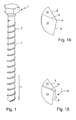
Figur 11 Figur 14- perspektivisch einen Ausschnitt aus einem Gewindegang;
Figur 15- perspektivisch einen Ausschnitt aus einem Gewindegang bei einer anderen Ausführungsform;
Figur 16- einen schematisierten Querschnitt durch eine Schraube.
- FIG. 1
- in perspective, the view of a concrete screw proposed by the invention;
- FIG. 2
- the side view of only the shaft of a concrete screw a first embodiment;
- FIG. 3
- a cross section through the screw of
FIG. 2 along line III-III; - FIG. 4
- a cross section through the screw of
FIG. 2 along line IV-IV inFIG. 2 ; - FIG. 5
- one of the
FIG. 2 corresponding representation of a screw in a second embodiment; - FIG. 6
- a cross section along line VI-VI in
FIG. 5 ; - FIG. 7
- a cross section through the screw of
FIG. 5 along line VII-VII; - FIG. 8
- a side view of a screw shaft of a third embodiment;
- FIG. 9
- a cross section along line IX-IX in
FIG. 8 ; - FIG. 10
- a cross section through the screw of
FIG. 8 along line XX; - FIG. 11
- a side view of a screw shaft of a fourth embodiment;
- FIG. 12
- a cross section along line XII-XII in
FIG. 11 ; - FIG. 13
- a cross section through the screw of
FIG. 11 along line XIII-XIII; - FIG. 14
- in perspective, a section of a thread;
- FIG. 15
- perspective view of a section of a thread in another embodiment;
- FIG. 16
- a schematic cross section through a screw.
In
Einzelheiten zu der Schraube sind in den folgenden Figuren dargestellt. Es wird jetzt auf die
Das gleiche gilt für das Gewinde drei, dessen Gewindekante 8 von der Längsachse 7 der Schraube einen Abstand aufweist, der sich innerhalb eines Umlaufs, der in
Dieser Querschnitt, der in
Im unteren Bereich der Schraube, also dem Einformbereich 4, ist der Querschnitt durch die Schraube in
Soweit ist der Verlauf des Gewindes in dem vorderen Bereich dargestellt. Der Querschnitt durch den Schraubenschaft 2 verläuft aber geringfügig anders. Der Querschnitt verläuft wiederum von einer Kreisform abweichend, hat aber in diesem Bereich fünf Maxima und fünf zwischen diesen liegende Minima des Abstands der Kontur des Schafts von der Längsachse 7. Einem Maximum des Abstands fällt jeweils mit jeder zweiten Kante 10 zwischen zwei Gewindeabschnitten zusammen. Angedeutet ist dies beim Bezugszeichen 11.As far as the course of the thread is shown in the front area. The cross section through the
Dieser mit fünf Maxima versehene Querschnitt des Schraubenschafts 2 ist über einen größeren Teil des Schraubenschafts 2 vorhanden als dies dem Einformbereich 4 entspricht. Dieser Bereich ist in
Die
In dem sich an den Einformbereich 4 anschließenden weiteren Bereich der Ausführungsform nach den
Die weitere Ausführungsform in
Nun zu der Ausführungsform, die in den
Wie man der Seitenansicht der
Bislang wurde bei dem Betongewinde 3, das sich um den Schaft 2 der Schraube herum erstreckt, nur der Verlauf der Gewindekante 8 näher erläutert. Abgesehen von den in der Draufsicht zu sehenden Ecken 9 verläuft bei den bisher dargestellten Ausführungsformen die Gewindekante als Linie. Dies kann man auch aus der perspektivischen Darstellung der
Es ist aber ebenfalls möglich, und hierzu wird auf die
Solche Stufen 15, wie sie in
Die
Das auf diesen Schaft 2 auf gewalzte Gewinde 3 weist eine Gewindekante 8 auf, die aus zehn gradlinigen Abschnitten besteht, die jeweils durch einen Knick 9 miteinander verbunden sind. Jeder zweite Knick 9 liegt in Umfangsrichtung deckungsgleich mit einer abgerundeten Ecke des Schaftquerschnitts.On this
Ein solcher Schaft mit dieser abgerundet fünfeckigen Form lässt sich durch Walzen einfacher herstellen, so dass sich der Aufwand beim Walzen verringert. Es hat sich herausgestellt, dass auch das Einschrauben einer solchen Schraube wegen der Form der Gewindekante 8 leichter geschieht, ohne dass die Gefahr des Ausbrechens bei hartem Material auftritt. Bei zu starkem Drücken der Gewindeform kann es zu Ausbrüchen des Betons und daher zum Ausreißen der Schraube kommen. Dies wird durch die dargestellte und beschriebene Form sowohl des Schraubenschafts als auch des Verlaufs der Gewindekante verhindert.Such a shaft with this rounded pentagonal shape can be made easier by rolling, so that reduces the cost of rolling. It has been found that the screwing of such a screw is easier due to the shape of the
Claims (12)
Applications Claiming Priority (1)
| Application Number | Priority Date | Filing Date | Title |
|---|---|---|---|
| DE102009041877A DE102009041877A1 (en) | 2009-09-07 | 2009-09-07 | concrete screw |
Publications (2)
| Publication Number | Publication Date |
|---|---|
| EP2292939A2 true EP2292939A2 (en) | 2011-03-09 |
| EP2292939A3 EP2292939A3 (en) | 2012-02-29 |
Family
ID=43302098
Family Applications (1)
| Application Number | Title | Priority Date | Filing Date |
|---|---|---|---|
| EP10174710A Withdrawn EP2292939A3 (en) | 2009-09-07 | 2010-08-31 | Concrete screw |
Country Status (2)
| Country | Link |
|---|---|
| EP (1) | EP2292939A3 (en) |
| DE (1) | DE102009041877A1 (en) |
Cited By (2)
| Publication number | Priority date | Publication date | Assignee | Title |
|---|---|---|---|---|
| WO2013102453A1 (en) * | 2012-01-03 | 2013-07-11 | Ruia Global Fasteners Ag | Self-tapping screw |
| WO2014131615A1 (en) * | 2013-02-26 | 2014-09-04 | Hilti Aktiengesellschaft | Concrete screw |
Citations (2)
| Publication number | Priority date | Publication date | Assignee | Title |
|---|---|---|---|---|
| EP0062279A1 (en) | 1981-03-31 | 1982-10-13 | Tandberg Data A/S | Method of detecting the edge of a magnetic medium and apparatus to realize this method |
| WO2006133542A1 (en) * | 2005-06-16 | 2006-12-21 | Walther, Gerda | Screw for use in concrete |
Family Cites Families (15)
| Publication number | Priority date | Publication date | Assignee | Title |
|---|---|---|---|---|
| US2352982A (en) * | 1942-06-25 | 1944-07-04 | American Screw Co | Screw for plastics |
| US3472119A (en) * | 1966-06-29 | 1969-10-14 | Hubbell Inc Harvey | Thread forming screw and method of making same |
| BE756647A (en) * | 1968-11-08 | 1971-03-25 | Keystone Consolidated Ind Inc | TAPPING SCREW. |
| US3681963A (en) * | 1970-01-19 | 1972-08-08 | Res Eng & Mfg | Self-thread forming threaded fasteners and method and apparatus for making the same |
| DE3272798D1 (en) * | 1982-02-18 | 1986-10-02 | Conti Fasteners Ag | Screw |
| DE9103773U1 (en) * | 1991-03-27 | 1992-07-30 | Reisser - Schraubenwerk Gmbh + Co, 7118 Kuenzelsau, De | |
| US6086302A (en) * | 1996-07-29 | 2000-07-11 | TOGE -- Dubel A. Gerhard KG | Self-tapping concrete screw for insertion in an associated drill hole in concrete |
| DE19801100A1 (en) * | 1998-01-15 | 1999-07-22 | Toge Duebel A Gerhard Kg | Tapping screw |
| DE29812526U1 (en) * | 1998-07-14 | 1999-11-25 | Fischer Artur Werke Gmbh | Thread forming screw |
| US6296433B1 (en) * | 2000-09-05 | 2001-10-02 | Illinois Tool Works Inc. | Large diameter tapcon with debris reservoir end or tip |
| DE10045274A1 (en) * | 2000-09-13 | 2002-03-21 | Toge Duebel A Gerhard Kg | Thread-forming screw, especially concrete screw |
| DE10107801A1 (en) * | 2001-02-19 | 2002-09-05 | Hilti Ag | concrete screw |
| DE10252774A1 (en) * | 2002-11-07 | 2004-05-27 | Adolf Würth GmbH & Co. KG | Screw for hard materials such as concrete or masonry comprises a thread having cutting teeth alternately arranged to the left and the right of an imaginary central line on the side facing away from the head |
| DE102006037006B4 (en) * | 2006-08-08 | 2014-08-07 | TOGE-Dübel A. Gerhard KG | Concrete screw |
| DE102007003518B4 (en) * | 2007-01-18 | 2017-12-07 | Adolf Würth GmbH & Co. KG | Screw, in particular for push-through installation of window frames in the reveal of masonry |
-
2009
- 2009-09-07 DE DE102009041877A patent/DE102009041877A1/en not_active Withdrawn
-
2010
- 2010-08-31 EP EP10174710A patent/EP2292939A3/en not_active Withdrawn
Patent Citations (2)
| Publication number | Priority date | Publication date | Assignee | Title |
|---|---|---|---|---|
| EP0062279A1 (en) | 1981-03-31 | 1982-10-13 | Tandberg Data A/S | Method of detecting the edge of a magnetic medium and apparatus to realize this method |
| WO2006133542A1 (en) * | 2005-06-16 | 2006-12-21 | Walther, Gerda | Screw for use in concrete |
Cited By (3)
| Publication number | Priority date | Publication date | Assignee | Title |
|---|---|---|---|---|
| WO2013102453A1 (en) * | 2012-01-03 | 2013-07-11 | Ruia Global Fasteners Ag | Self-tapping screw |
| US9297403B2 (en) | 2012-01-03 | 2016-03-29 | Ruia Global Fasteners Ag | Self-tapping screw |
| WO2014131615A1 (en) * | 2013-02-26 | 2014-09-04 | Hilti Aktiengesellschaft | Concrete screw |
Also Published As
| Publication number | Publication date |
|---|---|
| EP2292939A3 (en) | 2012-02-29 |
| DE102009041877A1 (en) | 2011-03-10 |
Similar Documents
| Publication | Publication Date | Title |
|---|---|---|
| DE4333791C2 (en) | Tapping screw | |
| EP0918164B1 (en) | Distance adjusting screw | |
| WO2010003901A1 (en) | Screw | |
| EP2806174A1 (en) | Screw element | |
| WO2015110377A1 (en) | Screw, fastening arrangement and use of a screw | |
| DE102019207681A1 (en) | Connecting element | |
| EP2522864B1 (en) | Wood or plastic screw | |
| DE102013203151A1 (en) | concrete screw | |
| DE102016101910A1 (en) | Plastic threaded element and connection arrangement consisting of a plastic carrier part and a plastic threaded element | |
| DE102015223473A1 (en) | Socket, fastener and method for placing a fastener on a workpiece | |
| EP1813827B1 (en) | Screw and method to manufacture a screw | |
| EP0504782B1 (en) | Screw, method and rolling die for manufacturing the same | |
| EP2292939A2 (en) | Concrete screw | |
| EP3374649B1 (en) | Thread-forming screw | |
| EP2367644B1 (en) | Method and rolling die for producing a screw | |
| WO2017102376A1 (en) | Threaded element | |
| EP2895751B1 (en) | Screw and use thereof | |
| EP1498618A2 (en) | Screw for hard materials | |
| DE2703433A1 (en) | THREAD FORMING SCREW AND METHOD OF MANUFACTURING THE SAME AND ROLLING JAW FOR PERFORMING THE METHOD | |
| DE10252774A1 (en) | Screw for hard materials such as concrete or masonry comprises a thread having cutting teeth alternately arranged to the left and the right of an imaginary central line on the side facing away from the head | |
| DE102007003518B4 (en) | Screw, in particular for push-through installation of window frames in the reveal of masonry | |
| EP3004665A1 (en) | Thread former and rolling die | |
| EP3726072B1 (en) | Screw for wooden materials | |
| EP2261517A1 (en) | Thread tapping screw | |
| DE2303747C2 (en) | Screw element with self-locking effect, especially when screwing into a threaded hole with a conventional thread |
Legal Events
| Date | Code | Title | Description |
|---|---|---|---|
| PUAI | Public reference made under article 153(3) epc to a published international application that has entered the european phase |
Free format text: ORIGINAL CODE: 0009012 |
|
| AK | Designated contracting states |
Kind code of ref document: A2 Designated state(s): AL AT BE BG CH CY CZ DE DK EE ES FI FR GB GR HR HU IE IS IT LI LT LU LV MC MK MT NL NO PL PT RO SE SI SK SM TR |
|
| AX | Request for extension of the european patent |
Extension state: BA ME RS |
|
| PUAL | Search report despatched |
Free format text: ORIGINAL CODE: 0009013 |
|
| AK | Designated contracting states |
Kind code of ref document: A3 Designated state(s): AL AT BE BG CH CY CZ DE DK EE ES FI FR GB GR HR HU IE IS IT LI LT LU LV MC MK MT NL NO PL PT RO SE SI SK SM TR |
|
| AX | Request for extension of the european patent |
Extension state: BA ME RS |
|
| RIC1 | Information provided on ipc code assigned before grant |
Ipc: F16B 25/00 20060101AFI20120125BHEP |
|
| 17P | Request for examination filed |
Effective date: 20120828 |
|
| 17Q | First examination report despatched |
Effective date: 20131118 |
|
| STAA | Information on the status of an ep patent application or granted ep patent |
Free format text: STATUS: THE APPLICATION IS DEEMED TO BE WITHDRAWN |
|
| 18D | Application deemed to be withdrawn |
Effective date: 20141008 |