EP2292931A2 - Hermetic type compressor - Google Patents
Hermetic type compressor Download PDFInfo
- Publication number
- EP2292931A2 EP2292931A2 EP10169038A EP10169038A EP2292931A2 EP 2292931 A2 EP2292931 A2 EP 2292931A2 EP 10169038 A EP10169038 A EP 10169038A EP 10169038 A EP10169038 A EP 10169038A EP 2292931 A2 EP2292931 A2 EP 2292931A2
- Authority
- EP
- European Patent Office
- Prior art keywords
- electric component
- bracket
- fastening
- hermetic
- hermetic container
- Prior art date
- Legal status (The legal status is an assumption and is not a legal conclusion. Google has not performed a legal analysis and makes no representation as to the accuracy of the status listed.)
- Withdrawn
Links
- 230000006835 compression Effects 0.000 claims description 12
- 238000007906 compression Methods 0.000 claims description 12
- 239000003507 refrigerant Substances 0.000 claims description 11
- 239000011800 void material Substances 0.000 claims description 3
- 230000001012 protector Effects 0.000 description 4
- 238000001816 cooling Methods 0.000 description 3
- 239000002184 metal Substances 0.000 description 3
- 230000002950 deficient Effects 0.000 description 2
- 238000004519 manufacturing process Methods 0.000 description 2
- 238000003466 welding Methods 0.000 description 2
- 230000003993 interaction Effects 0.000 description 1
Images


Classifications
-
- F—MECHANICAL ENGINEERING; LIGHTING; HEATING; WEAPONS; BLASTING
- F04—POSITIVE - DISPLACEMENT MACHINES FOR LIQUIDS; PUMPS FOR LIQUIDS OR ELASTIC FLUIDS
- F04C—ROTARY-PISTON, OR OSCILLATING-PISTON, POSITIVE-DISPLACEMENT MACHINES FOR LIQUIDS; ROTARY-PISTON, OR OSCILLATING-PISTON, POSITIVE-DISPLACEMENT PUMPS
- F04C23/00—Combinations of two or more pumps, each being of rotary-piston or oscillating-piston type, specially adapted for elastic fluids; Pumping installations specially adapted for elastic fluids; Multi-stage pumps specially adapted for elastic fluids
- F04C23/008—Hermetic pumps
-
- F—MECHANICAL ENGINEERING; LIGHTING; HEATING; WEAPONS; BLASTING
- F04—POSITIVE - DISPLACEMENT MACHINES FOR LIQUIDS; PUMPS FOR LIQUIDS OR ELASTIC FLUIDS
- F04B—POSITIVE-DISPLACEMENT MACHINES FOR LIQUIDS; PUMPS
- F04B39/00—Component parts, details, or accessories, of pumps or pumping systems specially adapted for elastic fluids, not otherwise provided for in, or of interest apart from, groups F04B25/00 - F04B37/00
- F04B39/12—Casings; Cylinders; Cylinder heads; Fluid connections
- F04B39/121—Casings
-
- F—MECHANICAL ENGINEERING; LIGHTING; HEATING; WEAPONS; BLASTING
- F04—POSITIVE - DISPLACEMENT MACHINES FOR LIQUIDS; PUMPS FOR LIQUIDS OR ELASTIC FLUIDS
- F04B—POSITIVE-DISPLACEMENT MACHINES FOR LIQUIDS; PUMPS
- F04B39/00—Component parts, details, or accessories, of pumps or pumping systems specially adapted for elastic fluids, not otherwise provided for in, or of interest apart from, groups F04B25/00 - F04B37/00
- F04B39/14—Provisions for readily assembling or disassembling
-
- F—MECHANICAL ENGINEERING; LIGHTING; HEATING; WEAPONS; BLASTING
- F04—POSITIVE - DISPLACEMENT MACHINES FOR LIQUIDS; PUMPS FOR LIQUIDS OR ELASTIC FLUIDS
- F04C—ROTARY-PISTON, OR OSCILLATING-PISTON, POSITIVE-DISPLACEMENT MACHINES FOR LIQUIDS; ROTARY-PISTON, OR OSCILLATING-PISTON, POSITIVE-DISPLACEMENT PUMPS
- F04C2240/00—Components
- F04C2240/30—Casings or housings
-
- F—MECHANICAL ENGINEERING; LIGHTING; HEATING; WEAPONS; BLASTING
- F04—POSITIVE - DISPLACEMENT MACHINES FOR LIQUIDS; PUMPS FOR LIQUIDS OR ELASTIC FLUIDS
- F04C—ROTARY-PISTON, OR OSCILLATING-PISTON, POSITIVE-DISPLACEMENT MACHINES FOR LIQUIDS; ROTARY-PISTON, OR OSCILLATING-PISTON, POSITIVE-DISPLACEMENT PUMPS
- F04C2240/00—Components
- F04C2240/80—Other components
- F04C2240/803—Electric connectors or cables; Fittings therefor
Definitions
- Embodiments of the present invention relate to a hermetic compressor in which an electric component bracket installed on an outer surface of a hermetic container for connection to an electric component cover may be easily changed and replaced with a new one.
- a hermetic compressor employed in a cooling apparatus of an air conditioner or a refrigerator to compress a refrigerant includes a compression unit and a drive unit provided in a hermetic container.
- the compression unit performs compression of the refrigerant and the drive unit provides a driving force to compress the refrigerant.
- the drive unit generally includes a motor and connection terminals are installed on the hermetic container to supply power to the drive unit.
- connection terminal One end of each connection terminal is exposed to an outside of the hermetic container and the other end of each connection terminal is connected to the driving unit within the hermetic container.
- Electric components relating to driving of the drive unit such as an overload protector and a relay, are connected to the ends of the connection terminals exposed to the outside of the hermetic container.
- An electric component bracket for connection to the electric component cover is provided on an outer surface of the hermetic container surrounding the connection terminals.
- the electric component bracket is made of a thin metal sheet and is fixed to the outer surface of the hermetic container by welding.
- a hole for exposing the connection terminals is formed through the centre of the electric component bracket and fastening structures for fastening to the electric component cover are provided at an edge of the electric component bracket.
- the electric components are connected to the connection terminals when the electric component bracket is welded onto the outer surface of the hermetic container and, in this state, the electric component cover is connected to the electric component bracket so as to cover the electric components.
- the number and/or type of the electric components may change according to the specifications of the hermetic compressor.
- the electric component cover covering the new electric components needs to be changed.
- the electric component bracket also needs to be replaced with a new bracket corresponding to the new electric component cover.
- the electric component cover may be changed in accordance with an internal structure of the cooling apparatus in which the hermetic compressor is installed even if the same electric components are used. In this case, the electric component bracket needs to be replaced to correspond to the new electric component cover.
- various types of electric component brackets are required according to user requirements and other variables.
- a hermetic compressor includes a hermetic container provided with a compression unit for compressing a refrigerant, and a drive unit to provide a driving force to compress the refrigerant, connection terminals passing through the hermetic container for connection to electric components for driving the drive unit, an electric component cover for protecting the electric components connected to the connection terminals located at an outside of the hermetic container, and an electric component bracket installed on an outer surface of the hermetic container surrounding the connection terminals for fastening to the electric component cover, wherein bracket fixing members having first fastening units are provided on the outer surface of the hermetic container around the connection terminals so as to detachably connect the electric component bracket to the outer surface of the hermetic container and second fastening units to which the first fastening units are detachably connected are provided on the electric component bracket.
- Third fastening units may be provided on the electric component bracket and fourth fastening units to which the third fastening units are detachably connected may be provided on the electric component cover.
- a plurality of bracket fixing members may be provided.
- Three bracket fixing members may be disposed in a triangle.
- the bracket fixing members may be welded to the outer surface of the hermetic container.
- Each first fastening unit may include a protrusion part which protrudes outwardly from the outer surface of the hermetic container and a hanging part having a cross-sectional area greater than that of the protrusion part provided at an end of the protrusion part, wherein each second fastening unit may include a hanging part pass-hole to accommodate the hanging part, a protrusion part fitting hole formed at the top of the hanging part pass-hole so that the protrusion part fitting hole and the hanging part pass-hole define a single void, wherein each second fastening unit may have a width corresponding to a width of the protrusion part such that the protrusion part may be fitted into the protrusion part fitting hole.
- a plurality of bracket fixing members may be provided surrounding the connection terminals and separated from each other by a designated interval in the circumferential direction and a plurality of second fastening units may be provided for fastening to the first fastening units if the electric component bracket is rotated after the the second fastening units are located between the bracket fixing members.
- One of a first fastening unit and a second fastening unit may include an arc-shaped fitting groove and the other of a first fastening unit and a second fastening unit may include a fitting part for fitting into the fitting groove while sliding in the circumferential direction.
- the fitting part may be fitted into the fitting groove by an interference fit.
- a hermetic compressor in accordance with embodiments of the present invention is employed in a cooling apparatus of a refrigerator or an air conditioner to compress a refrigerant and includes a hermetic container forming an external facade of the hermetic compressor.
- a compression unit for compressing the refrigerant and a drive unit for providing a driving force to compress the refrigerant are installed in the hermetic container.
- the drive unit includes a motor having a stator and a rotor; a rotary shaft transmitting the driving force of the drive unit to the compression unit is connected to the rotor.
- the compression unit includes a piston connected to an eccentric part formed at one end of the rotary shaft through a connecting rod and reciprocates rectilinearly within a compression chamber.
- hermetic compressor in accordance with embodiments of the present invention is generally connected to a reciprocating compressor including a compression unit having a connecting rod and a piston.
- hermetic compressors in accordance with further embodiments of the present invention are rotary compressors.
- Compressors of embodiments of the invention include a drive unit driven by power regardless of the types of compression units provided.
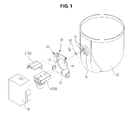
- FIG. 1 illustrates a hermetic compressor in accordance with an embodiment of the present invention.
- a hermetic container 1 is formed by connecting an upper container (not shown) and a lower container 10 to each other.
- Connection terminals 31 for connecting electric components 20 for driving the drive unit, i.e., applying power to the drive unit, are installed at one side of the lower container 10.
- the connection terminals 31 are installed on the lower container 10 with a terminal housing 30.
- the terminal housing 30 passes through one side of the lower container 10 and the connection terminals 31 pass through the terminal housing 30 such that one end of each connection terminal 31 is exposed to an outside of the hermetic container 1.
- the other end of each connection terminal 31 is connected to the drive unit in the hermetic container 1.
- Electric components 20 for driving the drive unit including an overload protector 21 and a relay 22, are connected to the ends of the connection terminals 31 exposed to the outside of the hermetic container 1.
- Various kinds of overload protector 21 and the relay 22 may be used.
- the electric components 20 may include other electronic components for driving the drive unit in addition to the overload protector 21 and the relay 22.
- the electric components 20 located at the outside of the hermetic container 1 are covered with an electric component cover 40, and an electric component bracket 50 for connection to the electric component cover 40 is provided on the outer surface of the hermetic container 1 encasing the connection terminals 31.
- the hermetic compressor in accordance with this embodiment is configured such that the electric component bracket 50 is easily replaced with a new one according to user requirements or other variables.
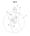
- bracket fixing members 60 are provided on the outer surface of the lower container 10 in proximity to the connection terminals 31 such that the electric component bracket 50 may be detachably connected to the bracket fixing members 60.
- First fastening units 61 are provided on the bracket fixing members 60 and second fastening units 51, detachably connected to the first fastening units 61, are provided on the electric component bracket 50.
- the electric component bracket 50 may be simply and easily replaced with a new one.
- the bracket fixing members 60 are formed in the shape of a small metal piece, and most regions of the bracket fixing members 60 form the respectively first fastening units 61.
- the first fastening unit 61 of each bracket fixing member 60 includes a protrusion part 61 a which protrudes outwardly from the outer surface of the hermetic container 1 when each bracket fixing member 60 is installed on the outer surface of the hermetic container and a hanging part 61 b having a cross-sectional area greater than that of the protrusion part 61 a provided at one end of the protrusion part 61 a.
- the end of the protrusion part 61 a opposite to the hanging part 61 b forms a fixing surface 62 welded to the outer surface of the lower container 10 to attach each bracket fixing member 60 to the lower container 10.
- the electric component bracket 50 is a thin metal sheet.
- An exposure hole 52 allows exposure of the connection terminals 31.
- the terminal housing 30 is formed in the centre of the electric component bracket 50.
- each second fastening unit 51 is provided in the shape of a hole formed in the electric component bracket 50 surrounding the exposure hole 52.
- each second fastening unit 51 includes a hanging part pass-hole 51 a formed to allow passage therethrough of the hanging part 61 b of the first fastening unit 61 and a protrusion part fitting hole 51 b formed above the hanging part pass-hole 51 a having a width corresponding to the width of the protrusion part 61 a such that the protrusion part 61 a of the first fastening unit 61 fits into the protrusion part fitting hole 51 b.
- the hanging part pass-hole 51 a and the protrusion part fitting hole 51 b are formed so as to form part of the same void.
- a length of the protrusion part fitting hole 51 b in the vertical direction may be equal to or greater than the length of the protrusion part 61 a in the vertical direction.
- the electric component bracket 50 is fastened to the bracket fixing members 60.
- the bracket fixing members 60 are welded onto the hermetic container 1.
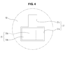
- the electric component bracket 50 moves toward the hermetic container 1 under the condition that the electric component bracket 50 is located in front of the bracket fixing members 60 such that the hanging parts 61 b of the first fastening units 61 and the hanging part pass-holes 51 a of the second fastening units 51 coincide with each other, as shown in FIGS. 3 and 4 , the hanging parts 61 b of the first fastening units 61 pass through the hanging part pass-holes 51 a of the second fastening units 51.
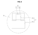
- the electric component bracket 50 may be pulled downwards so as to fit the protrusion parts 61 a of the first fastening units 61 into the protrusion part fitting holes 51 b of the second fastening units 51, as shown in FIGS. 5 and 6 .
- the electric component bracket 50 is fastened to the bracket fixing members 60 by hanging the hanging parts 61 b of the first fastening units 61 onto the protrusion part fitting holes 51 b of the second fastening units 51 in a simple manner.
- the electric component bracket 50 When the electric component bracket 50 is pulled forward, away from the hermetic container 1, under the condition that the electric component bracket 50 is lifted up so that the hanging parts 61 b of the first fastening units 61 and the hanging part pass-holes 51a of the second fastening units 51 coincide with each other, the hanging parts 61 b disengage from the hanging part pass-holes 51a.
- the electric component bracket 50 is thereby again separated from the bracket fixing members 60. Therefore, the electric component bracket 50 is firmly fixed to the bracket fixing members 60 unless the hanging parts 61 b of the first fastening units 61 disengage from the hanging part pass-holes 51a of the second fastening units 51 by lifting up the electric component bracket 50 fastened to the bracket fixing members 60.
- bracket fixing members 60 may be provided surrounding the connection terminals 31.
- three bracket fixing members 60 are disposed in a triangle around the terminal housing 30, thereby supporting the electric component bracket 50 at three points.
- a protruding length of the protrusion parts 61a of the first fastening units 61 may be about equal to a thickness of the electric component bracket 50.
- FIG. 7 illustrates the electric component cover 40 separated from the electric component bracket 50 which is fixed to the outer surface of the hermetic container 1 by the bracket fixing members 60.
- the electric component cover 40 is provided in the shape of a box having the surface orientated, when installed, toward the hermetic container 1, open.
- the electric component cover 40 is an injection-moulded product made of plastic which is elastically deformable and has relatively thin walls compared to the dimensions of the box.
- the electric component cover 40 is detachably connected to the electric component bracket 50.
- third fastening units 53 are provided on the electric component bracket 50 and fourth fastening units 41, to which the third fastening units 53 are detachably connected, are provided on the electric component cover 40.
- the third fastening units 53 are formed at an edge of the electric component bracket 50 so as not to interfere with the first fastening units 61 of the bracket fixing members 60.
- Each third fastening unit 53 includes a protrusion piece 53a which protrudes toward the electric component cover 40 and a hanging hole 53b formed in the protrusion piece 53a.
- each fourth fastening unit 41 includes a support piece 41 a provided at an inside of a side wall of the electric component cover 40 and separated from the side wall of the electric component cover 40 so as to be supported by an inner surface of the protrusion piece 53a.
- Each fourth fastening unit 41 includes a hanging protrusion 41 b which protrudes from the outer surface of the support piece 41 a to fit into the hanging hole 53b.
- the support piece 41 a may be sufficiently thin to elastically deform with ease.
- the electric component bracket 50 and the electric component cover 40 are detachably fastened to one another when the electric component bracket 50 is fixed to the outer surface of the lower container 10 by the bracket fixing members 60.
- the electric component cover 40 is pressed toward the hermetic container 1 while contacting the front surface of the electric component bracket 50 so as to fit the hanging protrusions 41 b of the fourth fastening units 41 into the hanging holes 53b of the third fastening units 53.
- the electric component bracket 50 is detachably connected to the outer surface of the hermetic container 1 through the first fastening units 61 of the bracket fixing members 60 being connected to the outer surface of the hermetic container 1 and the second fastening units 51 being provided on the electric component bracket 50.
- the electric component bracket 50 may be replaced with other electric component brackets differing in any aspect other than the size and shape of the second fastening units 51. Furthermore, the electric component bracket 50 may be replaced to fit a new component cover 40, provided that the electric bracket 50 and the component cover 40 engage in a similar manner.
- the electric component bracket 50 is fastened to the outer surface of the hermetic container 1 in a simple fit manner.
- a manufacturer of hermetic compressors may manufacturer a hermetic compressor provided with only the bracket fixing members 60 and without the electric component bracket 50 and then provides the hermetic compressor to a user. The user may however easily prepare the electric component bracket 50 to be detachably connected to the bracket fixing members 50 of the supplied hermetic compressor. Therefore a manufacturer may provide various kinds of electric component brackets having different shapes to a user and the user may then select the required electric component bracket provided that the electric component brackets have the same structure for the second fastening units.
- bracket fixing members and the second fastening units provided to detachably connect the electric component bracket to the bracket fixing members may be modified into various types and shapes.
- a pair of bracket fixing members 60' is disposed surrounding connection terminals 31 such that the bracket fixing members 60' are separated from one another by a designated interval in the circumferential direction.
- at least three bracket fixing members 60' may be provided, so that the bracket fixing members 60' are disposed around the connection terminals 31 separated from each other by a designated interval in the circumferential direction.
- a pair of second fastening units 51' is also provided on an electric component bracket 50' to correspond to the number of the bracket fixing members 60'.
- the electric component bracket 50' is rotated so that the second fastening units 51' enter an area between the bracket fixing members 60', the second fastening units 51' are fastened with first fastening units 61' provided on the bracket fixing members 60'.
- each second fastening unit 51' is provided on a rear surface of the electric component bracket 50' around an exposure hole 52 such that the second fastening units 51' are separated from each other by a designated interval in the circumferential direction.
- each second fastening unit 51' includes an extension part 51 a' which extends rearwardly from the rear surface of the electric component bracket 50' and a fitting part 51 b' extending from the extension part 51 a' in the radial direction parallel with the electric component bracket 50'.
- each first fastening unit 61' includes a fitting groove into which the fitting part 51' of the second fastening unit 51' fits when slid in the circumferential direction due to rotation of the electric component bracket 50'. That is, the bracket fixing member 60' is formed to have an arc-shaped cross-section in a direction parallel to the electric component bracket 50' and an L-shaped cross-section in a direction perpendicular to the electric component bracket 50' and is welded to the outer surface of the hermetic container 10.
- the first fastening unit 61' is an arc-shaped fitting groove formed between the bracket fixing member 60' and the outer surface of the hermetic container 10.
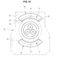
- the fitting parts 51 b' of the second fastening units 51' enter the area between the bracket fixing members 60' when the electric component bracket 50' is rotated through an angle of 90 degrees, as shown in FIG. 9 . Thereafter, when the electric component bracket 50' is rotated through an angle of 90 degrees in the clockwise direction so as to stand upright, as shown in FIG. 10 , the fitting parts 51 b' of the second fastening units 51' fit into the first fastening units 61'. In this manner the electric component bracket 50' is simply and easily connected to the outer surface of the hermetic container 10.
- the fitting parts 51 b' and the first fastening units 61' may be connected to each by an interference fit. Further, in order to complete fastening of the first fastening units 61' and the second fastening units 51' to one another when the electric component bracket 50' stands upright (in the orientation shown in FIG. 10 ), a restriction protrusion 63 for restricting sliding of the fitting part 51 b' is provided at an end of each first fastening unit 61'.
- the electric component bracket 50' In order to separate the electric component bracket 50' fixed to the outer surface of the hermetic container 10 from the hermetic container 10, the electric component bracket 50' is rotated in the counterclockwise direction from the orientation shown in FIG. 10 to the orientation shown in FIG. 9 . Thereby, the fitting parts 51 b' disengage from the first fastening units 61' and then the electric component bracket 50' is simply and easily separated from the hermetic container 10.
- a hermetic compressor in accordance with embodiments of the present invention enables an electric component bracket for connection with an electric component cover to be detachably connected to the outer surface of a hermetic container by bracket fixing members.
- the hermetic compressor in accordance with the embodiment of the present invention, if replacement of the electric component bracket is required according to user requirements or other variables, for example if the type of the electric component cover is changed due to a change in the number or the kinds of electric components, if the design of the electric component cover is changed or if the electric component bracket is damaged, the electric component bracket may be simply and easily replaced with a new one, and a design the electric component bracket may be more easily changed.
Abstract
Description
- Embodiments of the present invention relate to a hermetic compressor in which an electric component bracket installed on an outer surface of a hermetic container for connection to an electric component cover may be easily changed and replaced with a new one.
- In general, a hermetic compressor employed in a cooling apparatus of an air conditioner or a refrigerator to compress a refrigerant includes a compression unit and a drive unit provided in a hermetic container. The compression unit performs compression of the refrigerant and the drive unit provides a driving force to compress the refrigerant.
- The drive unit generally includes a motor and connection terminals are installed on the hermetic container to supply power to the drive unit.
- One end of each connection terminal is exposed to an outside of the hermetic container and the other end of each connection terminal is connected to the driving unit within the hermetic container. Electric components relating to driving of the drive unit, such as an overload protector and a relay, are connected to the ends of the connection terminals exposed to the outside of the hermetic container.
- Such electric components are protected by an electric component cover. An electric component bracket for connection to the electric component cover is provided on an outer surface of the hermetic container surrounding the connection terminals.
- In the conventional hermetic container, the electric component bracket is made of a thin metal sheet and is fixed to the outer surface of the hermetic container by welding. A hole for exposing the connection terminals is formed through the centre of the electric component bracket and fastening structures for fastening to the electric component cover are provided at an edge of the electric component bracket.
- Therefore, the electric components are connected to the connection terminals when the electric component bracket is welded onto the outer surface of the hermetic container and, in this state, the electric component cover is connected to the electric component bracket so as to cover the electric components.
- However, the conventional hermetic container in which the electric component bracket is fixed to the outer surface of the hermetic container by welding exhibits difficulty in replacing the electric component bracket, which is inconvenient.
- In the conventional hermetic container, if the electric component bracket is partially damaged or is defective, replacement of only the electric component bracket is difficult and thus the entire hermetic container including the electric component bracket is often replaced with a new one.
- Further, the number and/or type of the electric components may change according to the specifications of the hermetic compressor. When the number or type of the electric components are changed, the electric component cover covering the new electric components needs to be changed. Furthermore, the electric component bracket also needs to be replaced with a new bracket corresponding to the new electric component cover. Further, the electric component cover may be changed in accordance with an internal structure of the cooling apparatus in which the hermetic compressor is installed even if the same electric components are used. In this case, the electric component bracket needs to be replaced to correspond to the new electric component cover. In other words, various types of electric component brackets are required according to user requirements and other variables.
- However, since the replacement of an electric component bracket fixed to the hermetic container with a different type of electric component bracket is difficult, if a new electric component bracket having a different specification is required in a conventional manufacturing line for hermetic compressors, it is necessary to prepare new manufacturing equipment to install the new electric component bracket on the outer surface of the hermetic container.
- Therefore, it is an aspect of the present invention to provide a hermetic compressor in which an electric component bracket installed on the outer surface of a hermetic container for connection to an electric component cover is easily replaced with a new one and may be changed in design according to user requirements and other variables.
- Additional aspects of the invention will be set forth in the description which follows and, in part, will be obvious from the description, or may be learned by practice of the invention.
- In accordance with one aspect of the present invention, a hermetic compressor includes a hermetic container provided with a compression unit for compressing a refrigerant, and a drive unit to provide a driving force to compress the refrigerant, connection terminals passing through the hermetic container for connection to electric components for driving the drive unit, an electric component cover for protecting the electric components connected to the connection terminals located at an outside of the hermetic container, and an electric component bracket installed on an outer surface of the hermetic container surrounding the connection terminals for fastening to the electric component cover, wherein bracket fixing members having first fastening units are provided on the outer surface of the hermetic container around the connection terminals so as to detachably connect the electric component bracket to the outer surface of the hermetic container and second fastening units to which the first fastening units are detachably connected are provided on the electric component bracket.
- Third fastening units may be provided on the electric component bracket and fourth fastening units to which the third fastening units are detachably connected may be provided on the electric component cover.
- A plurality of bracket fixing members may be provided.
- Three bracket fixing members may be disposed in a triangle.
- The bracket fixing members may be welded to the outer surface of the hermetic container.
- Each first fastening unit may include a protrusion part which protrudes outwardly from the outer surface of the hermetic container and a hanging part having a cross-sectional area greater than that of the protrusion part provided at an end of the protrusion part, wherein each second fastening unit may include a hanging part pass-hole to accommodate the hanging part, a protrusion part fitting hole formed at the top of the hanging part pass-hole so that the protrusion part fitting hole and the hanging part pass-hole define a single void, wherein each second fastening unit may have a width corresponding to a width of the protrusion part such that the protrusion part may be fitted into the protrusion part fitting hole.
- A plurality of bracket fixing members may be provided surrounding the connection terminals and separated from each other by a designated interval in the circumferential direction and a plurality of second fastening units may be provided for fastening to the first fastening units if the electric component bracket is rotated after the the second fastening units are located between the bracket fixing members.
- One of a first fastening unit and a second fastening unit may include an arc-shaped fitting groove and the other of a first fastening unit and a second fastening unit may include a fitting part for fitting into the fitting groove while sliding in the circumferential direction.
- The fitting part may be fitted into the fitting groove by an interference fit.
- These and/or other aspects of the invention will become apparent and more readily appreciated from the following description of the embodiments, taken in conjunction with the accompanying drawings in which:
-
FIG. 1 is an exploded perspective view of a structure of a hermetic compressor in accordance with one embodiment of the present invention illustrating connection terminals; -
FIG. 2 is an extracted perspective view of a portion of the structure of the hermetic compressor in accordance with the embodiment ofFIG. 1 , illustrating a connection of bracket fixing members to a lower container; -
FIG. 3 is an extracted perspective view of a portion of the structure of the hermetic compressor in accordance with the embodiment ofFIG. 1 , illustrating connection of the bracket fixing members to the hermetic container ofFIG. 2 ; -
FIG. 4 is an enlarged plan view illustrating a first fastening unit of the bracket fixing member and a second fastening unit of the electric component bracket ofFIG. 3 ; -
FIG. 5 is an extracted perspective view of a portion of the structure of the hermetic compressor in accordance with the embodiment ofFIG. 1 , illustrating completion of the connection of the bracket fixing members to the hermetic container ofFIG. 3 ; -
FIG. 6 is an enlarged plan view illustrating the first fastening unit of the bracket fixing member and the second fastening unit of the electric component bracket ofFIG. 5 ; -
FIG. 7 is a perspective view of a structure of connecting parts between the electric component bracket and an electric component cover in the hermetic compressor in accordance with the embodiment ofFIG. 1 prior to connection of the electric component cover to the electric component bracket; -
FIG. 8 is a perspective view illustrating bracket fixing members and an electric component bracket separated from a hermetic container in a hermetic compressor in accordance with another embodiment of the present invention; -
FIG. 9 is a front view of the hermetic, illustrating connection of the electric component bracket to the hermetic container ofFIG. 8 ; and -
FIG. 10 is a front view of the hermetic compressor, illustrating completion of the connection of the electric component bracket to the hermetic container ofFIG. 9 . - Reference will now be made in detail to the embodiments of the present invention, examples of which are illustrated in the accompanying drawings and wherein like reference numerals refer to like elements throughout.
- A hermetic compressor in accordance with embodiments of the present invention is employed in a cooling apparatus of a refrigerator or an air conditioner to compress a refrigerant and includes a hermetic container forming an external facade of the hermetic compressor.
- A compression unit for compressing the refrigerant and a drive unit for providing a driving force to compress the refrigerant are installed in the hermetic container. The drive unit includes a motor having a stator and a rotor; a rotary shaft transmitting the driving force of the drive unit to the compression unit is connected to the rotor.
- The compression unit includes a piston connected to an eccentric part formed at one end of the rotary shaft through a connecting rod and reciprocates rectilinearly within a compression chamber.
- When the rotor is rotated by means of electrical interaction between the stator and the rotor when power is applied to the stator through the structure described above, the rotary shaft connected to the rotor is rotated by rotation of the rotor, and the piston connected to the eccentric part of the rotary shaft through the connecting rod reciprocates rectilinearly within the compression chamber, thereby compressing the refrigerant.
- The hermetic compressor in accordance with embodiments of the present invention is generally connected to a reciprocating compressor including a compression unit having a connecting rod and a piston. However, hermetic compressors in accordance with further embodiments of the present invention are rotary compressors. Compressors of embodiments of the invention include a drive unit driven by power regardless of the types of compression units provided.
-
FIG. 1 illustrates a hermetic compressor in accordance with an embodiment of the present invention. Ahermetic container 1 is formed by connecting an upper container (not shown) and alower container 10 to each other.Connection terminals 31 for connectingelectric components 20 for driving the drive unit, i.e., applying power to the drive unit, are installed at one side of thelower container 10. Theconnection terminals 31 are installed on thelower container 10 with aterminal housing 30. Theterminal housing 30 passes through one side of thelower container 10 and theconnection terminals 31 pass through theterminal housing 30 such that one end of eachconnection terminal 31 is exposed to an outside of thehermetic container 1. The other end of eachconnection terminal 31 is connected to the drive unit in thehermetic container 1.Electric components 20 for driving the drive unit, including an overload protector 21 and arelay 22, are connected to the ends of theconnection terminals 31 exposed to the outside of thehermetic container 1. Various kinds of overload protector 21 and therelay 22 may be used. Furthermore, theelectric components 20 may include other electronic components for driving the drive unit in addition to the overload protector 21 and therelay 22. - The
electric components 20 located at the outside of thehermetic container 1 are covered with anelectric component cover 40, and anelectric component bracket 50 for connection to theelectric component cover 40 is provided on the outer surface of thehermetic container 1 encasing theconnection terminals 31. - The hermetic compressor in accordance with this embodiment is configured such that the
electric component bracket 50 is easily replaced with a new one according to user requirements or other variables. - With reference to
FIGS. 1 to 6 , in a hermetic compressor in accordance with this embodiment,bracket fixing members 60 are provided on the outer surface of thelower container 10 in proximity to theconnection terminals 31 such that theelectric component bracket 50 may be detachably connected to thebracket fixing members 60.First fastening units 61 are provided on thebracket fixing members 60 andsecond fastening units 51, detachably connected to thefirst fastening units 61, are provided on theelectric component bracket 50. - Therefore, in the hermetic compressor, if replacement of the
electric component bracket 50 is required according to user requirements or other variables, such as if the type of theelectric component cover 40 is changed due to a change in the number or type of theelectric components 20, if the design of theelectric component cover 40 is changed or if theelectric component bracket 50 is damaged, theelectric component bracket 50 may be simply and easily replaced with a new one. - The
bracket fixing members 60 are formed in the shape of a small metal piece, and most regions of thebracket fixing members 60 form the respectivelyfirst fastening units 61. Thefirst fastening unit 61 of eachbracket fixing member 60 includes aprotrusion part 61 a which protrudes outwardly from the outer surface of thehermetic container 1 when eachbracket fixing member 60 is installed on the outer surface of the hermetic container and a hangingpart 61 b having a cross-sectional area greater than that of theprotrusion part 61 a provided at one end of theprotrusion part 61 a. The end of theprotrusion part 61 a opposite to the hangingpart 61 b forms a fixingsurface 62 welded to the outer surface of thelower container 10 to attach eachbracket fixing member 60 to thelower container 10. - In this embodiment, the
electric component bracket 50 is a thin metal sheet. Anexposure hole 52 allows exposure of theconnection terminals 31. Theterminal housing 30 is formed in the centre of theelectric component bracket 50. In this embodiment, eachsecond fastening unit 51 is provided in the shape of a hole formed in theelectric component bracket 50 surrounding theexposure hole 52. - In more detail, each
second fastening unit 51 includes a hanging part pass-hole 51 a formed to allow passage therethrough of the hangingpart 61 b of thefirst fastening unit 61 and a protrusion partfitting hole 51 b formed above the hanging part pass-hole 51 a having a width corresponding to the width of theprotrusion part 61 a such that theprotrusion part 61 a of thefirst fastening unit 61 fits into the protrusion partfitting hole 51 b. The hanging part pass-hole 51 a and the protrusion partfitting hole 51 b are formed so as to form part of the same void. A length of the protrusion partfitting hole 51 b in the vertical direction may be equal to or greater than the length of theprotrusion part 61 a in the vertical direction. - The
electric component bracket 50 is fastened to thebracket fixing members 60. Thebracket fixing members 60 are welded onto thehermetic container 1. When theelectric component bracket 50 moves toward thehermetic container 1 under the condition that theelectric component bracket 50 is located in front of thebracket fixing members 60 such that the hangingparts 61 b of thefirst fastening units 61 and the hanging part pass-holes 51 a of thesecond fastening units 51 coincide with each other, as shown inFIGS. 3 and4 , the hangingparts 61 b of thefirst fastening units 61 pass through the hanging part pass-holes 51 a of thesecond fastening units 51. Thereafter, theelectric component bracket 50 may be pulled downwards so as to fit theprotrusion parts 61 a of thefirst fastening units 61 into the protrusion part fitting holes 51 b of thesecond fastening units 51, as shown inFIGS. 5 and6 . Thereby, theelectric component bracket 50 is fastened to thebracket fixing members 60 by hanging the hangingparts 61 b of thefirst fastening units 61 onto the protrusion part fitting holes 51 b of thesecond fastening units 51 in a simple manner. - When the
electric component bracket 50 is pulled forward, away from thehermetic container 1, under the condition that theelectric component bracket 50 is lifted up so that the hangingparts 61 b of thefirst fastening units 61 and the hanging part pass-holes 51a of thesecond fastening units 51 coincide with each other, the hangingparts 61 b disengage from the hanging part pass-holes 51a. Theelectric component bracket 50 is thereby again separated from thebracket fixing members 60. Therefore, theelectric component bracket 50 is firmly fixed to thebracket fixing members 60 unless the hangingparts 61 b of thefirst fastening units 61 disengage from the hanging part pass-holes 51a of thesecond fastening units 51 by lifting up theelectric component bracket 50 fastened to thebracket fixing members 60. - In order to maintain the fastening of the
electric component bracket 50 to the outer surface of thehermetic container 1, two or morebracket fixing members 60 may be provided surrounding theconnection terminals 31. In this embodiment, threebracket fixing members 60 are disposed in a triangle around theterminal housing 30, thereby supporting theelectric component bracket 50 at three points. - Further, in order to prevent movement of the
electric component bracket 50 fastened to thebracket fixing members 60, a protruding length of theprotrusion parts 61a of thefirst fastening units 61 may be about equal to a thickness of theelectric component bracket 50. -
FIG. 7 illustrates theelectric component cover 40 separated from theelectric component bracket 50 which is fixed to the outer surface of thehermetic container 1 by thebracket fixing members 60. - The
electric component cover 40 is provided in the shape of a box having the surface orientated, when installed, toward thehermetic container 1, open. Theelectric component cover 40 is an injection-moulded product made of plastic which is elastically deformable and has relatively thin walls compared to the dimensions of the box. - The
electric component cover 40 is detachably connected to theelectric component bracket 50. For this purpose,third fastening units 53 are provided on theelectric component bracket 50 andfourth fastening units 41, to which thethird fastening units 53 are detachably connected, are provided on theelectric component cover 40. - The
third fastening units 53 are formed at an edge of theelectric component bracket 50 so as not to interfere with thefirst fastening units 61 of thebracket fixing members 60. Eachthird fastening unit 53 includes aprotrusion piece 53a which protrudes toward theelectric component cover 40 and a hanginghole 53b formed in theprotrusion piece 53a. - Furthermore, each
fourth fastening unit 41 includes asupport piece 41 a provided at an inside of a side wall of theelectric component cover 40 and separated from the side wall of theelectric component cover 40 so as to be supported by an inner surface of theprotrusion piece 53a. Eachfourth fastening unit 41 includes a hangingprotrusion 41 b which protrudes from the outer surface of thesupport piece 41 a to fit into the hanginghole 53b. Thesupport piece 41 a may be sufficiently thin to elastically deform with ease. - Therefore, the
electric component bracket 50 and theelectric component cover 40 are detachably fastened to one another when theelectric component bracket 50 is fixed to the outer surface of thelower container 10 by thebracket fixing members 60. In this manner, theelectric component cover 40 is pressed toward thehermetic container 1 while contacting the front surface of theelectric component bracket 50 so as to fit the hangingprotrusions 41 b of thefourth fastening units 41 into the hangingholes 53b of thethird fastening units 53. - When the
electric component cover 40 is to be separated from theelectric component bracket 50, an external force is applied to both side walls of theelectric component cover 40 so as to cause both side walls to deform towards one another. Then, thesupport pieces 41 a of thefourth fastening units 41 are elastically deformed, and thus the hangingprotrusions 41 b are disengaged from the hangingholes 53b of thethird fastening units 53. By simply pulling theelectric component cover 40 forwardly from thehermetic container 3, theelectric component cover 40 is separated from theelectric component bracket 50. - As described above, in the hermetic compressor in accordance with this embodiment, the
electric component bracket 50 is detachably connected to the outer surface of thehermetic container 1 through thefirst fastening units 61 of thebracket fixing members 60 being connected to the outer surface of thehermetic container 1 and thesecond fastening units 51 being provided on theelectric component bracket 50. Thus, if theelectric component bracket 50 is defective or damaged, there is no need to replace the whole of thelower container 10 and only theelectric component bracket 50 need be replaced with a new one. - Further, in the hermetic compressor in accordance with this embodiment, as the
first fastening units 61 and thesecond fastening units 61 are detachably connected to each other, theelectric component bracket 50 may be replaced with other electric component brackets differing in any aspect other than the size and shape of thesecond fastening units 51. Furthermore, theelectric component bracket 50 may be replaced to fit anew component cover 40, provided that theelectric bracket 50 and thecomponent cover 40 engage in a similar manner. - Further, in the hermetic compressor in accordance with this embodiment, the
electric component bracket 50 is fastened to the outer surface of thehermetic container 1 in a simple fit manner. A manufacturer of hermetic compressors may manufacturer a hermetic compressor provided with only thebracket fixing members 60 and without theelectric component bracket 50 and then provides the hermetic compressor to a user. The user may however easily prepare theelectric component bracket 50 to be detachably connected to thebracket fixing members 50 of the supplied hermetic compressor. Therefore a manufacturer may provide various kinds of electric component brackets having different shapes to a user and the user may then select the required electric component bracket provided that the electric component brackets have the same structure for the second fastening units. - The bracket fixing members and the second fastening units provided to detachably connect the electric component bracket to the bracket fixing members may be modified into various types and shapes.
- As shown in
FIGS. 8 to 10 , in accordance with another embodiment of the present invention, a pair of bracket fixing members 60' is disposed surroundingconnection terminals 31 such that the bracket fixing members 60' are separated from one another by a designated interval in the circumferential direction. However, at least three bracket fixing members 60' may be provided, so that the bracket fixing members 60' are disposed around theconnection terminals 31 separated from each other by a designated interval in the circumferential direction. - A pair of second fastening units 51' is also provided on an electric component bracket 50' to correspond to the number of the bracket fixing members 60'. When the electric component bracket 50' is rotated so that the second fastening units 51' enter an area between the bracket fixing members 60', the second fastening units 51' are fastened with first fastening units 61' provided on the bracket fixing members 60'.
- The second fastening units 51' are provided on a rear surface of the electric component bracket 50' around an
exposure hole 52 such that the second fastening units 51' are separated from each other by a designated interval in the circumferential direction. In this embodiment, each second fastening unit 51' includes anextension part 51 a' which extends rearwardly from the rear surface of the electric component bracket 50' and afitting part 51 b' extending from theextension part 51 a' in the radial direction parallel with the electric component bracket 50'. - Furthermore, each first fastening unit 61' includes a fitting groove into which the fitting part 51' of the second fastening unit 51' fits when slid in the circumferential direction due to rotation of the electric component bracket 50'. That is, the bracket fixing member 60' is formed to have an arc-shaped cross-section in a direction parallel to the electric component bracket 50' and an L-shaped cross-section in a direction perpendicular to the electric component bracket 50' and is welded to the outer surface of the
hermetic container 10. The first fastening unit 61' is an arc-shaped fitting groove formed between the bracket fixing member 60' and the outer surface of thehermetic container 10. - Therefore, in this embodiment, in order to connect the electric component bracket 50' to the
hermetic container 10, thefitting parts 51 b' of the second fastening units 51' enter the area between the bracket fixing members 60' when the electric component bracket 50' is rotated through an angle of 90 degrees, as shown inFIG. 9 . Thereafter, when the electric component bracket 50' is rotated through an angle of 90 degrees in the clockwise direction so as to stand upright, as shown inFIG. 10 , thefitting parts 51 b' of the second fastening units 51' fit into the first fastening units 61'. In this manner the electric component bracket 50' is simply and easily connected to the outer surface of thehermetic container 10. - In order to prevent movement of the electric component bracket 50' when the first fastening units 61' and the second fastening units 51' are fastened to one another, the
fitting parts 51 b' and the first fastening units 61' may be connected to each by an interference fit. Further, in order to complete fastening of the first fastening units 61' and the second fastening units 51' to one another when the electric component bracket 50' stands upright (in the orientation shown inFIG. 10 ), arestriction protrusion 63 for restricting sliding of thefitting part 51 b' is provided at an end of each first fastening unit 61'. - In order to separate the electric component bracket 50' fixed to the outer surface of the
hermetic container 10 from thehermetic container 10, the electric component bracket 50' is rotated in the counterclockwise direction from the orientation shown inFIG. 10 to the orientation shown inFIG. 9 . Thereby, thefitting parts 51 b' disengage from the first fastening units 61' and then the electric component bracket 50' is simply and easily separated from thehermetic container 10. - Other aspects of this embodiment, except for the first and
second fastening units 61' and 51, are the same as those in the embodiment ofFIGS. 1 to 7 , and thus a description of the structure used for an attachment and detachment between the electric component bracket 50' and theelectric component cover 40 in this embodiment will be omitted. - As is apparent from the above description, a hermetic compressor in accordance with embodiments of the present invention enables an electric component bracket for connection with an electric component cover to be detachably connected to the outer surface of a hermetic container by bracket fixing members.
- Therefore, in the hermetic compressor in accordance with the embodiment of the present invention, if replacement of the electric component bracket is required according to user requirements or other variables, for example if the type of the electric component cover is changed due to a change in the number or the kinds of electric components, if the design of the electric component cover is changed or if the electric component bracket is damaged, the electric component bracket may be simply and easily replaced with a new one, and a design the electric component bracket may be more easily changed.
Claims (9)
- A hermetic compressor comprising:a hermetic container provided with a compression unit for compressing a refrigerant, and a drive unit to provide a driving force to compress the refrigerant;connection terminals passing through the hermetic container for connection to electric components for driving the drive unit;an electric component cover for protecting the electric components connected to the connection terminals located at an outside of the hermetic container; andan electric component bracket installed on an outer surface of the hermetic container surrounding the connection terminals for fastening to the electric component cover,wherein bracket fixing members having first fastening units are provided on the outer surface of the hermetic container surrounding the connection terminals so as to detachably connect the electric component bracket to the outer surface of the hermetic container and second fastening units to which the first fastening units are detachably connected are provided on the electric component bracket.
- The hermetic compressor according to claim 1, wherein third fastening units are provided on the electric component bracket and fourth fastening units, to which the third fastening units are detachably connected, are provided on the electric component cover.
- The hermetic compressor according to claim 1 or claim 2 comprising a plurality of bracket fixing members.
- The hermetic compressor according to claim 3, wherein three bracket fixing members are disposed in a triangle.
- The hermetic compressor according to any preceding claim 1, wherein the bracket fixing members are welded to the outer surface of the hermetic container.
- The hermetic compressor according to any preceding claim, wherein:each first fastening unit includes a protrusion part which protrudes outwardly from the outer surface of the hermetic container and a hanging part having a cross-sectional area greater than that of the protrusion part provided at an end of the protrusion part; whereineach second fastening unit includes a hanging part pass-hole to accommodate the hanging part, a protrusion part fitting hole formed at the top of the hanging part pass-hole so that the protrusion part fitting hole and the hanging part pass-hole define a single void, wherein each second fastening unit may have a width corresponding to a width of the protrusion part such that the protrusion part fits into the protrusion part fitting hole.
- The hermetic compressor according to claim 1, comprising:a plurality of bracket fixing members surrounding the connection terminals and separated from each other by a designated interval in the circumferential direction, anda plurality of second fastening units provided for fastening to the first fastening units if the electric component bracket is rotated after the second fastening units are located between the bracket fixing members.
- The hermetic compressor according to claim 7, wherein:one of a first fastening unit and a second fastening unit includes an arc-shaped fitting groove; andthe other of a first fastening unit and a second fastening unit includes a fitting part for fitting into the fitting groove while sliding in the circumferential direction.
- The hermetic compressor according to claim 8, wherein the fitting part is fitted into the fitting groove by an interference fit.
Applications Claiming Priority (1)
| Application Number | Priority Date | Filing Date | Title |
|---|---|---|---|
| KR1020090063414A KR101052777B1 (en) | 2009-07-13 | 2009-07-13 | Hermetic compressor |
Publications (2)
| Publication Number | Publication Date |
|---|---|
| EP2292931A2 true EP2292931A2 (en) | 2011-03-09 |
| EP2292931A3 EP2292931A3 (en) | 2013-08-21 |
Family
ID=42732224
Family Applications (1)
| Application Number | Title | Priority Date | Filing Date |
|---|---|---|---|
| EP10169038.6A Withdrawn EP2292931A3 (en) | 2009-07-13 | 2010-07-09 | Hermetic type compressor |
Country Status (3)
| Country | Link |
|---|---|
| US (1) | US20110008193A1 (en) |
| EP (1) | EP2292931A3 (en) |
| KR (1) | KR101052777B1 (en) |
Families Citing this family (6)
| Publication number | Priority date | Publication date | Assignee | Title |
|---|---|---|---|---|
| US8737330B2 (en) * | 2011-06-24 | 2014-05-27 | Motorola Mobility Llc | Multi-cluster uplink transmission in wireless communication network |
| JP6366819B2 (en) * | 2015-03-27 | 2018-08-01 | 三菱電機株式会社 | Fluid machinery |
| CN105517417B (en) * | 2015-12-25 | 2018-07-17 | 珠海格力电器股份有限公司 | Compressor electrical appliance kit and compressor with it |
| BR102016013775A2 (en) * | 2016-06-14 | 2017-12-26 | Whirlpool S.A. | ALTERNATIVE COMPRESSOR AND ALTERNATIVE COMPRESSOR HERMETIC HOUSING ASSEMBLY PROCESS |
| BR102018010404B1 (en) * | 2018-05-22 | 2023-10-17 | Whirlpool S.A. | REFRIGERATION COMPRESSOR COMPRISING PROTECTIVE ARRANGEMENT FOR ELECTRICAL CONNECTIONS |
| BR102018074735B1 (en) * | 2018-11-29 | 2022-06-07 | Embraco Indústria De Compressores E Soluções Em Refrigeração Ltda | Electrical arrangement mounting structure in the external region of the hermetic compressor housing |
Family Cites Families (11)
| Publication number | Priority date | Publication date | Assignee | Title |
|---|---|---|---|---|
| US5173057A (en) * | 1992-02-07 | 1992-12-22 | Tecumseh Products Company | Permanent protective cover |
| KR19990010276U (en) * | 1997-08-28 | 1999-03-15 | 전주범 | Wall structure of detachable air conditioner |
| KR20010000561U (en) * | 1999-06-14 | 2001-01-15 | 윤종용 | Power supply apparatus of compressor |
| JP3768114B2 (en) * | 2001-03-28 | 2006-04-19 | 三洋電機株式会社 | Compressor electrical components |
| KR100483557B1 (en) * | 2002-08-09 | 2005-04-15 | 삼성광주전자 주식회사 | Apparatus for mounting protection cover for hermetic compressor |
| US7290989B2 (en) * | 2003-12-30 | 2007-11-06 | Emerson Climate Technologies, Inc. | Compressor protection and diagnostic system |
| KR100659977B1 (en) * | 2004-11-03 | 2006-12-26 | 센서스앤드컨트롤스코리아 주식회사 | Clamp device for connecting package of refrigerator compressor |
| CN100487242C (en) * | 2005-12-28 | 2009-05-13 | 松下电器产业株式会社 | Electric equipment protective device |
| KR100663244B1 (en) * | 2006-02-01 | 2007-01-02 | (주)엔드테크 | The nebulizer to be applicable in various models and how to assemble it |
| KR101206809B1 (en) * | 2006-05-26 | 2012-11-30 | 삼성전자주식회사 | Hermetic type compressor |
| EP1884728A1 (en) * | 2006-08-01 | 2008-02-06 | ARYLUX S.p.A. | Terminal block assembly for the connection and control of sealed compressors particularly for home refrigerators |
-
2009
- 2009-07-13 KR KR1020090063414A patent/KR101052777B1/en active IP Right Grant
-
2010
- 2010-07-09 EP EP10169038.6A patent/EP2292931A3/en not_active Withdrawn
- 2010-07-09 US US12/833,691 patent/US20110008193A1/en not_active Abandoned
Non-Patent Citations (1)
| Title |
|---|
| None |
Also Published As
| Publication number | Publication date |
|---|---|
| KR101052777B1 (en) | 2011-07-29 |
| US20110008193A1 (en) | 2011-01-13 |
| KR20110006000A (en) | 2011-01-20 |
| EP2292931A3 (en) | 2013-08-21 |
Similar Documents
| Publication | Publication Date | Title |
|---|---|---|
| EP2292931A2 (en) | Hermetic type compressor | |
| US8668477B2 (en) | Series-connected fan unit | |
| EP3046237B1 (en) | Ceiling fan motor | |
| US10087942B2 (en) | Motor driven compressor | |
| JP2011144788A (en) | Motor-driven compressor | |
| JP5708592B2 (en) | Electric compressor | |
| US6559566B2 (en) | End shield constructed with a separate component holder | |
| JP6256387B2 (en) | Electric compressor | |
| JP6766666B2 (en) | Electric compressor | |
| US20150349613A1 (en) | Inverter-integrated electric compressor | |
| KR101573317B1 (en) | Motor-driven compressor | |
| CN106014912A (en) | Electric compressor | |
| CN106796036B (en) | The outdoor unit of air conditioner | |
| US20140377095A1 (en) | Motor-driven compressor | |
| CN104251189B (en) | Motor-driven compressor | |
| JP7263058B2 (en) | electric compressor | |
| KR101530116B1 (en) | Electric compressor | |
| KR200455461Y1 (en) | Multifunction distribution board | |
| EP2685605A2 (en) | Motor's stator unit | |
| JP6577398B2 (en) | Outdoor unit for refrigeration cycle apparatus and method for manufacturing outdoor unit for refrigeration cycle apparatus | |
| JP6418008B2 (en) | Electric compressor | |
| CN204084667U (en) | Fan assembly and there is its air-conditioner | |
| CN210197604U (en) | Electric control assembly of air conditioner and air conditioner with same | |
| EP2980502B1 (en) | Air conditioner | |
| CN210197494U (en) | Motor support assembly and air duct machine with same |
Legal Events
| Date | Code | Title | Description |
|---|---|---|---|
| PUAI | Public reference made under article 153(3) epc to a published international application that has entered the european phase |
Free format text: ORIGINAL CODE: 0009012 |
|
| AK | Designated contracting states |
Kind code of ref document: A2 Designated state(s): AL AT BE BG CH CY CZ DE DK EE ES FI FR GB GR HR HU IE IS IT LI LT LU LV MC MK MT NL NO PL PT RO SE SI SK SM TR |
|
| AX | Request for extension of the european patent |
Extension state: BA ME RS |
|
| RAP1 | Party data changed (applicant data changed or rights of an application transferred) |
Owner name: SAMSUNG ELECTRONICS CO., LTD. |
|
| RAP1 | Party data changed (applicant data changed or rights of an application transferred) |
Owner name: SAMSUNG ELECTRONICS CO., LTD. |
|
| PUAL | Search report despatched |
Free format text: ORIGINAL CODE: 0009013 |
|
| AK | Designated contracting states |
Kind code of ref document: A3 Designated state(s): AL AT BE BG CH CY CZ DE DK EE ES FI FR GB GR HR HU IE IS IT LI LT LU LV MC MK MT NL NO PL PT RO SE SI SK SM TR |
|
| AX | Request for extension of the european patent |
Extension state: BA ME RS |
|
| RIC1 | Information provided on ipc code assigned before grant |
Ipc: F04C 23/00 20060101AFI20130717BHEP Ipc: F04B 39/12 20060101ALI20130717BHEP |
|
| 17P | Request for examination filed |
Effective date: 20140220 |
|
| RBV | Designated contracting states (corrected) |
Designated state(s): AL AT BE BG CH CY CZ DE DK EE ES FI FR GB GR HR HU IE IS IT LI LT LU LV MC MK MT NL NO PL PT RO SE SI SK SM TR |
|
| STAA | Information on the status of an ep patent application or granted ep patent |
Free format text: STATUS: THE APPLICATION HAS BEEN WITHDRAWN |
|
| 18W | Application withdrawn |
Effective date: 20140702 |