EP2292450A1 - Heavy duty pneumatic tire - Google Patents
Heavy duty pneumatic tire Download PDFInfo
- Publication number
- EP2292450A1 EP2292450A1 EP10007744A EP10007744A EP2292450A1 EP 2292450 A1 EP2292450 A1 EP 2292450A1 EP 10007744 A EP10007744 A EP 10007744A EP 10007744 A EP10007744 A EP 10007744A EP 2292450 A1 EP2292450 A1 EP 2292450A1
- Authority
- EP
- European Patent Office
- Prior art keywords
- bead core
- organic fiber
- cords
- bead
- fiber cords
- Prior art date
- Legal status (The legal status is an assumption and is not a legal conclusion. Google has not performed a legal analysis and makes no representation as to the accuracy of the status listed.)
- Granted
Links
- 239000011324 bead Substances 0.000 claims abstract description 142
- 239000000835 fiber Substances 0.000 claims abstract description 42
- 229910000831 Steel Inorganic materials 0.000 claims abstract description 41
- 239000010959 steel Substances 0.000 claims abstract description 41
- 238000004804 winding Methods 0.000 claims abstract description 12
- 238000010073 coating (rubber) Methods 0.000 claims abstract description 7
- 230000000149 penetrating effect Effects 0.000 claims abstract description 4
- 230000003014 reinforcing effect Effects 0.000 description 6
- 238000005452 bending Methods 0.000 description 3
- 230000003247 decreasing effect Effects 0.000 description 3
- 238000000926 separation method Methods 0.000 description 3
- 230000007423 decrease Effects 0.000 description 2
- 238000004898 kneading Methods 0.000 description 2
- 239000000463 material Substances 0.000 description 2
- 230000008520 organization Effects 0.000 description 2
- 229920001875 Ebonite Polymers 0.000 description 1
- 229920000297 Rayon Polymers 0.000 description 1
- 229920002978 Vinylon Polymers 0.000 description 1
- 239000004760 aramid Substances 0.000 description 1
- 229920003235 aromatic polyamide Polymers 0.000 description 1
- 239000011248 coating agent Substances 0.000 description 1
- 238000000576 coating method Methods 0.000 description 1
- 230000008878 coupling Effects 0.000 description 1
- 238000010168 coupling process Methods 0.000 description 1
- 238000005859 coupling reaction Methods 0.000 description 1
- 230000000694 effects Effects 0.000 description 1
- 239000000945 filler Substances 0.000 description 1
- 230000020169 heat generation Effects 0.000 description 1
- 230000000116 mitigating effect Effects 0.000 description 1
- 229920001778 nylon Polymers 0.000 description 1
- 229920000728 polyester Polymers 0.000 description 1
- 239000002964 rayon Substances 0.000 description 1
- 238000004073 vulcanization Methods 0.000 description 1
Images


Classifications
-
- B—PERFORMING OPERATIONS; TRANSPORTING
- B60—VEHICLES IN GENERAL
- B60C—VEHICLE TYRES; TYRE INFLATION; TYRE CHANGING; CONNECTING VALVES TO INFLATABLE ELASTIC BODIES IN GENERAL; DEVICES OR ARRANGEMENTS RELATED TO TYRES
- B60C15/00—Tyre beads, e.g. ply turn-up or overlap
- B60C15/04—Bead cores
-
- B—PERFORMING OPERATIONS; TRANSPORTING
- B60—VEHICLES IN GENERAL
- B60C—VEHICLE TYRES; TYRE INFLATION; TYRE CHANGING; CONNECTING VALVES TO INFLATABLE ELASTIC BODIES IN GENERAL; DEVICES OR ARRANGEMENTS RELATED TO TYRES
- B60C9/00—Reinforcements or ply arrangement of pneumatic tyres
- B60C9/02—Carcasses
- B60C2009/0269—Physical properties or dimensions of the carcass coating rubber
- B60C2009/0276—Modulus; Hardness; Loss modulus or "tangens delta"
-
- B—PERFORMING OPERATIONS; TRANSPORTING
- B60—VEHICLES IN GENERAL
- B60C—VEHICLE TYRES; TYRE INFLATION; TYRE CHANGING; CONNECTING VALVES TO INFLATABLE ELASTIC BODIES IN GENERAL; DEVICES OR ARRANGEMENTS RELATED TO TYRES
- B60C15/00—Tyre beads, e.g. ply turn-up or overlap
- B60C15/04—Bead cores
- B60C2015/044—Bead cores characterised by a wrapping layer
-
- B—PERFORMING OPERATIONS; TRANSPORTING
- B60—VEHICLES IN GENERAL
- B60C—VEHICLE TYRES; TYRE INFLATION; TYRE CHANGING; CONNECTING VALVES TO INFLATABLE ELASTIC BODIES IN GENERAL; DEVICES OR ARRANGEMENTS RELATED TO TYRES
- B60C15/00—Tyre beads, e.g. ply turn-up or overlap
- B60C15/04—Bead cores
- B60C2015/048—Polygonal cores characterised by the winding sequence
-
- B—PERFORMING OPERATIONS; TRANSPORTING
- B60—VEHICLES IN GENERAL
- B60C—VEHICLE TYRES; TYRE INFLATION; TYRE CHANGING; CONNECTING VALVES TO INFLATABLE ELASTIC BODIES IN GENERAL; DEVICES OR ARRANGEMENTS RELATED TO TYRES
- B60C2200/00—Tyres specially adapted for particular applications
- B60C2200/06—Tyres specially adapted for particular applications for heavy duty vehicles
-
- Y—GENERAL TAGGING OF NEW TECHNOLOGICAL DEVELOPMENTS; GENERAL TAGGING OF CROSS-SECTIONAL TECHNOLOGIES SPANNING OVER SEVERAL SECTIONS OF THE IPC; TECHNICAL SUBJECTS COVERED BY FORMER USPC CROSS-REFERENCE ART COLLECTIONS [XRACs] AND DIGESTS
- Y10—TECHNICAL SUBJECTS COVERED BY FORMER USPC
- Y10T—TECHNICAL SUBJECTS COVERED BY FORMER US CLASSIFICATION
- Y10T152/00—Resilient tires and wheels
- Y10T152/10—Tires, resilient
- Y10T152/10495—Pneumatic tire or inner tube
- Y10T152/10819—Characterized by the structure of the bead portion of the tire
- Y10T152/10846—Bead characterized by the chemical composition and or physical properties of elastomers or the like
-
- Y—GENERAL TAGGING OF NEW TECHNOLOGICAL DEVELOPMENTS; GENERAL TAGGING OF CROSS-SECTIONAL TECHNOLOGIES SPANNING OVER SEVERAL SECTIONS OF THE IPC; TECHNICAL SUBJECTS COVERED BY FORMER USPC CROSS-REFERENCE ART COLLECTIONS [XRACs] AND DIGESTS
- Y10—TECHNICAL SUBJECTS COVERED BY FORMER USPC
- Y10T—TECHNICAL SUBJECTS COVERED BY FORMER US CLASSIFICATION
- Y10T152/00—Resilient tires and wheels
- Y10T152/10—Tires, resilient
- Y10T152/10495—Pneumatic tire or inner tube
- Y10T152/10855—Characterized by the carcass, carcass material, or physical arrangement of the carcass materials
- Y10T152/10864—Sidewall stiffening or reinforcing means other than main carcass plies or foldups thereof about beads
Definitions
- the present invention relates to a heavy duty pneumatic tire, more particularly to a bead structure capable of preventing breakage of carcass cords occurring in the vicinity of the axially inner end of the bead core.
- heavy duty pneumatic tires for trucks, buses and the like are provided with a carcass reinforced by steel cords extending between bead portions and turned up around a bead core in each of the bead portions from the axially inside to the axially outside of the tire.
- the heavy duty pneumatic tires have a high probability of being used under extremely severe service conditions with heavy loads and very high tire inflation pressure. Therefore, there is a possibility that the steel carcass cords are broken in the vicinity of the bead core.
- a heavy duty pneumatic tire comprises
- the necessary distance between the steel carcass cords and the steel wire of the bead core can be maintained even under extremely severe service conditions, and breakage of the carcass cords can be effectively prevented and the bead durability is improved.
- the normally inflated unloaded condition is such that the tire is mounted on a standard wheel rim and inflate to a standard pressure but loaded with no tire load.
- the "hardness” of rubber means a hardness measured with a type-A durometer according to Japanese Industrial Standard K6253.
- the tread reinforcing belt 7 is composed of at least three plies, including at least two cross plies, each made of parallel steel cords.
- the belt 7 is composed of four plies: a radially innermost first ply 7A made of steel cords laid at an angle in a range of from 45 to 75 degrees with respect to the tire equator C and radially outer second, third and fourth plies 7B, 7C and 7D each made of steel cords laid at an angle in a range of from 10 to 35 degrees with respect to the tire equator C.
- the carcass 6 is composed of at least one ply 6A of steel carcass cords 6c arranged radially at an angle in the range of from 70 to 90 degrees with respect to the tire equator CO, extending between the bead portions 4 through the tread portion 2 and sidewall portions 3 and turned up around the bead core 5 in each bead portion 4 from the axially inside to the axially outside of the tire so as to form a pair of turnup portions 6b and a main portion 6a therebetween.
- the carcass ply 6A is rubberized with topping rubber Tg1 and both sides of the carcass ply 6A are covered with the topping rubber Tg1 of a certain thickness as shown in Fig.4 .
- Each of the bead portions 4 is provided between the main portion 6a and turned up portion 6b with a bead apex 8 extending radially outwardly from the bead core 5 in a tapered manner in order to reinforce the bead portion.
- the bead reinforcing cord layer 9 comprises: a base portion 9a positioned radially inside the bead core 5; an axially inner portion 9i extending radially outwardly from the base portion 9a along the axially inner surface of the carcass main portion 6a; and an axially outer portion 9o extending radially outwardly from the base portion 9a along the axially outer surface of the carcass turned up portion 6b, thereby having a u-shaped cross section.
- the hardness Hs3 of the clinch rubber layer 20 is more than the hardness Hs2 of the radially outer apex 8b and less than the hardness Hs1 of the radially inner apex 8a.
- the above-mentioned bead core 5 is, as shown in Figs.3 and 4 , composed of: a bead core main 10 made of a large number of windings of a steel wire 5w; a rubber coating 12 penetrating into the bead core main 10 and coating the surface of the steel wire 5w; and a bead core wrapping layer 11 surrounding the bead core main 10.
- the bead core main 10 in this example has a hexagonal cross-sectional shape which is elongated in a direction substantially parallel with the bead bottom surface 4s, and has: a radially inner surface SL substantially flat and substantially parallel with the bead seat Rs of the wheel rim when the tire is mounted; a radially outer surface su substantially parallel with the radially inner surface SL; an axially outer V-shaped bent surface; and an axially inner V-shaped bent surface of which bent point is the axially innermost end of the bead core main 10.
- the length L2 of the radially inner surface SL is more than 1.0 times, more preferably not less than 1.6 times the thickness T of the bead core main measured between the radially inner surface SL and radially outer surface SU. Therefore, the bead core main 10 can provide a tightening effect on a relatively wide range across the bead base, and further, the bead core main 10 can exert a greater resistance against a torsional deformation. Thus, the bead portions are fastened on the bead seats Rs of the wheel rim.
- the bead core wrapping layer 11 is, as shown in Figs.3 and 4 , composed of at least one ply 11A of parallel organic fiber cords 11a rubberized with a topping rubber Tg2.
- the hardness Ht2 of the topping rubber Tg2 is set in a range of not less than 70 degrees, preferably not less than 72 degrees, but not more than 90 degrees, preferably not more than 88 degrees.
- nylon fiber cords 11a of the bead core wrapping layer 11 nylon fiber cords, rayon fiber cords, polyester fiber cords, aromatic polyamide fiber cords, vinylon fiber cords and the like can be used.
- the fineness D1 of the organic fiber cord 11a is set in a range of not less than 940 dtex, preferably not less than 1670 dtex, but not more than 4200 dtex, preferably not more than 3960 dtex.
- the distances w1 between the organic fiber cords 11a are set in a range of not less than 0.3 mm, preferably not less than 0.4 mm, but not more than 1.4 mm, preferably not more than 1.3 mm.
- the above-mentioned rubber coating 12 of the bead core main 10 has a hardness Hb which is set in a range of not less than 78 degrees, but not more than 90 degrees in order to prevent breakage of the carcass cords by preventing deformation of the bead core main 10.
- the minimum distance L1 between the carcass cord 6c and the axially innermost steel wire 5w1 (or the axially innermost winding) of the bead core main 10 is set in a range of not less than 0.8 mm, preferably not less than 1.0 mm, but not more than 3.0 mm. preferably not more than 2.5 mm.
- the minimum distance L1 is more than 3.0 mm, due to heat generation during running, there is a possibility that a separation failure occurs between the carcass cords 6c and the bead core main 10. If the minimum distance L1 is less than 0.8 mm, there is a possibility that the carcass cords 6c contact with the steel wire 5w.
- the minimum distance L1 can be maintained even under extremely severe service conditions, and the direct contact between the steel carcass cords and the steel wire of the bead core can be avoided.
- the hardness Ht2 of the topping rubber Tg2 of the bead core wrapping layer 11 is less than 70 degrees, there is a possibility that the carcass cords 6c sink into the bead core wrapping layer 11 and contact with the steel wire 5w of the bead core 5, and as a result the carcass cords are worn down. If the hardness Ht2 is more than 90 degrees, there is a possibility of rubber burn during kneading of the topping rubber materials, and as a result, the strength and quality of the bead core wrapping layer 11 are decreased.
- each organic fiber cord 11a is less than 940 dtex, it becomes difficult to maintain the minimum distance L1, and breakage of the carcass cord is liable to occur.
- fineness D1 is more than 4200 dtex, it becomes difficult to fit the bead core wrapping layer 11 onto the bead core main 10, and as a result, it becomes difficult to maintain the ordered arrangement of the windings of the steel wire 5w.
- the distances w1 between organic fiber cords 11a are less than 0.3 mm, the coupling between the organic fiber cords 11a by the topping rubber Tg2 decreases, and there is a possibility that the carcass cords 6c sink into the bead core wrapping layer 11 and contact with the steel wire 5w. If the distances w1 are more than 1.4 mm, there is a possibility that the carcass cords 6c sink into the bead core wrapping layer 11 and contact with the steel wire 5w.
- the inclination angle ⁇ 1 of the organic fiber cords 11a is less than 20 degrees, there is a possibility that the organic fiber cords 11a sink between the windings of the steel wire 5w. If the inclination angle ⁇ 1 is more than 70 degrees, there is a possibility that the organic fiber cords 11a sink between the carcass cords. In either case, the distance between the carcass cords 6c and the steel wire 5w is decreased, therefore, there is a possibility that the carcass cords 6c contact with the steel wire 5w.
- Fig.6 shows another example of the above-mentioned bead core wrapping layer 11.
- two plies 11A1 and 11A2 are wound as the bead core wrapping layer 11 around the bead core main 10.
- the inclination angle ⁇ 1 of the parallel organic fiber cords 11a of one ply 11A1 and the inclination angle ⁇ 1 of the parallel organic fiber cords 11a of the other ply 11A2 with respect to the tire circumferential direction have same absolute values within the above-mentioned range. Therefore, the carcass cords 6c are effectively prevented from sinking into the bead core wrapping layer 11. Accordingly, direct contact between the carcass cords 6c and steel wire 5w1 can be prevented, and the breakage of the carcass cords is prevented.
- Heavy duty pneumatic tires of size 385/65R22.5 having the structure shown in Fig.1 and specifications shown in Table 1 were prepared and tested for the bead durability.
- each test tire mounted on a wheel rim of sixe 22.5x11.75 and inflated to 1100 kPa was run until the tire was broken under the following accelerated conditions, and the running time was measured.
- the minimum acceptable running time is 450 hours.
Landscapes
- Engineering & Computer Science (AREA)
- Mechanical Engineering (AREA)
- Tires In General (AREA)
Abstract
Description
- The present invention relates to a heavy duty pneumatic tire, more particularly to a bead structure capable of preventing breakage of carcass cords occurring in the vicinity of the axially inner end of the bead core.
- In general, heavy duty pneumatic tires for trucks, buses and the like are provided with a carcass reinforced by steel cords extending between bead portions and turned up around a bead core in each of the bead portions from the axially inside to the axially outside of the tire. The heavy duty pneumatic tires have a high probability of being used under extremely severe service conditions with heavy loads and very high tire inflation pressure. Therefore, there is a possibility that the steel carcass cords are broken in the vicinity of the bead core.
- Conventionally, in order to prevent the carcass cords from being broken by direct contacts with the steel wire of the bead core, the bead core is wrapped with a high modulus rubber layer for example as disclosed in us patent No.
7604032 2007-230400A - In recent years, on the other hand, in view of environment improvements, tire manufactures make great efforts to reduce tire weight even in the heavy duty pneumatic tires for trucks, buses and the like.
- In order to reduce the tire weight, for example, the number of carcass ply is reduced to one (single ply), and the volume of rubber such as bead apex, reinforcing layer, filler etc. used in the bead portions is decreased as disclosed in
us patent No. 7604032 . - As a result, the motion of the carcass ply during running is increased in the case of such a heavy duty pneumatic tire (hereinafter "heavy duty pneumatic tire with slim beads"). Therefore, it becomes difficult for the conventional high modulus rubber layer to fully prevent the carcass cords from contacting with the steel wire of the bead core, and thus it is difficult to provide bead durability.
- It is therefore, an object of the present invention to provide a heavy duty pneumatic tire (especially with slim beads), in which breakages of carcass cords are effectively prevented, and bead durability can be improved.
- According to the present invention, a heavy duty pneumatic tire comprises
- a tread portion,
- a pair of sidewall portions,
- a pair of bead portions each with a bead core therein, and
- a carcass ply of steel cords extending between the bead portions and turned up around the bead core in each said bead portion from the inside to the outside of the tire so as to form a pair of turned up portions and a main portion therebetween, wherein
- the steel cords of the carcass ply are rubberized with a topping rubber having a hardness Ht1 of from 68 to 90 degrees,
- the bead core is composed of
- a bead core main made of windings of a steel wire,
- a rubber coating penetrating into the bead core main and having a hardness Hb of from 78 to 90 degrees, and
- a bead core wrapping layer surrounding the bead core main and composed of at least one ply of parallel organic fiber cords rubberized with a topping rubber having a hardness Ht2 of from 70 to 90 degrees,
- the fineness of each of the organic fiber cords of the bead core wrapping layer in a range of from 940 to 4200 dtex,
- the distances between the organic fiber cords of the bead core wrapping layer are in a range of from 0.3 to 1.4 mm,
- the organic fiber cords of the bead core wrapping layer are inclined at an angle α1 in a range of from 20 to 70 degrees with respect to the tire circumferential direction, and
- a minimum distance between the carcass cords and the axially innermost winding of the steel wire of the bead core main is in a range of from 0.8 to 3.0 mm.
- Therefore, the necessary distance between the steel carcass cords and the steel wire of the bead core can be maintained even under extremely severe service conditions, and breakage of the carcass cords can be effectively prevented and the bead durability is improved.
- In this application including specification and claims, various dimensions, positions and the like of the tire refer to those under a normally inflated unloaded condition of the tire unless otherwise noted.
- The normally inflated unloaded condition is such that the tire is mounted on a standard wheel rim and inflate to a standard pressure but loaded with no tire load.
- The standard wheel rim is a wheel rim officially approved for the tire by standard organization, i.e. JATMA (Japan and Asia), T&RA (North America), ETRTO (Europe), STRO (Scandinavia) and the like. The standard pressure is the maximum air pressure for the tire specified by the same organization in the Air-pressure/Maximum-load Table or similar list. For example, the standard wheel rim is the "standard rim" specified in JATMA, the "Measuring Rim" in ETRTO, the "Design Rim" in TRA or the like. The standard pressure is the "maximum air pressure" in JATMA, the "Inflation Pressure" in ETRTO, the maximum pressure given in the "Tire Load Limits at various cold Inflation Pressures" table in TRA or the like.
- The "hardness" of rubber means a hardness measured with a type-A durometer according to Japanese Industrial Standard K6253.
-
-
Fig.1 is a cross sectional view of a heavy duty pneumatic tire according to the present invention. -
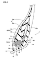
Fig.2 is an enlarged cross sectional view of the bead portion thereof. -
Fig.3 is an enlarged cross sectional view of the bead core thereof. -
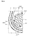
Fig.4 is an enlarged cross sectional view showing the vicinity of the axially innermost end of the bead core thereof. -
Fig.5 is a schematic plan view of the bead core showing the cord arrangement of the bead core wrapping layer thereof. -
Fig.6 is a schematic cross sectional view showing another example of the bead core wrapping layer. -
Fig.7 is a schematic plan view of the bead core shown inFig.6 showing the cord arrangement of the bead core wrapping layer. - Embodiments of the present invention will now be described in detail in conjunction with the accompanying drawings.
- In the drawings, a heavy duty
pneumatic tire 1 according to the present invention comprises atread portion 2, a pair ofsidewall portions 3, a pair of axially spacedbead portions 4 each with abead core 5 therein, acarcass 6 extending between thebead portions 4, and atread reinforcing belt 7 disposed radially outside thecarcass 6 in thetread portion 2. - The
tread reinforcing belt 7 is composed of at least three plies, including at least two cross plies, each made of parallel steel cords. - In this embodiment, the
belt 7 is composed of four plies: a radially innermostfirst ply 7A made of steel cords laid at an angle in a range of from 45 to 75 degrees with respect to the tire equator C and radially outer second, third andfourth plies - The
carcass 6 is composed of at least oneply 6A ofsteel carcass cords 6c arranged radially at an angle in the range of from 70 to 90 degrees with respect to the tire equator CO, extending between thebead portions 4 through thetread portion 2 andsidewall portions 3 and turned up around thebead core 5 in eachbead portion 4 from the axially inside to the axially outside of the tire so as to form a pair ofturnup portions 6b and amain portion 6a therebetween. - In this embodiment, the
carcass 6 is composed of asingle ply 6A of steel carcass cords arranged radially at an angle of 90 degrees with respect to the tire equator CO. - The
carcass ply 6A is rubberized with topping rubber Tg1 and both sides of thecarcass ply 6A are covered with the topping rubber Tg1 of a certain thickness as shown inFig.4 . - The hardness Ht1 of the topping rubber Tg1 is set in a range of not less than 68 degrees, preferably not less than 70 degrees, but not more than 90 degrees, preferably not more than 88 degrees. If the hardness Ht1 is less than 68 degrees, the topping rubber tends to flow during tire vulcanization and the covering thickness of the topping rubber decreases. As a result, there is a possibility that the carcass cords are broken. If the hardness Ht1 is more than 90 degrees, there is a possibility of rubber burn during kneading the topping rubber materials.
- Each of the
bead portions 4 is provided between themain portion 6a and turned upportion 6b with abead apex 8 extending radially outwardly from thebead core 5 in a tapered manner in order to reinforce the bead portion. - The
bead apex 8 in this embodiment is as shown inFig.2 , composed of a radiallyinner apex 8a made of a hard rubber layer having a hardness Hs1 of from 80 to 95 degrees, and a radiallyouter apex 8b made of a rubber softer than theinner apex 8a. Preferably, the hardness Hs2 of the radiallyouter apex 8b is set in a range of from 50 to 65 degrees. - As a result, when the
bead portion 4 is subjected to bending deformation, thebead apex 8 can provide a sufficient bending rigidity, while mitigating the share stress which the turned upportion 6b of thecarcass ply 6A is subjected to. Thus, damages such as carcass ply separation failure and the like can be effectively prevented. - Further, each of the
bead portions 4 is, as shown inFigs.2 and3 , provided with a bead reinforcingcord layer 9 in order to increase the bending rigidity of thebead portion 4. - The bead reinforcing
cord layer 9 is composed of a single ply of steel cords inclined at an angle of from 10 to 60 degrees with respect to the tire circumferential direction. - The bead reinforcing
cord layer 9 comprises: abase portion 9a positioned radially inside thebead core 5; an axiallyinner portion 9i extending radially outwardly from thebase portion 9a along the axially inner surface of the carcassmain portion 6a; and an axially outer portion 9o extending radially outwardly from thebase portion 9a along the axially outer surface of the carcass turned upportion 6b, thereby having a u-shaped cross section. - Furthermore, each of the
bead portions 4 is, as shown inFig.2 , provided with aclinch rubber layer 20 so as to cover an area contacting with a wheel rim when the tire is mounted thereon. Thus, theclinch rubber layer 20 has: abase part 20a extending from the bead toe to the bead heel so as to define thebead bottom surface 4s; an axiallyouter part 20b extending radially outwardly from the bead heel so as to define an axially outer surface of the bead portion contacting with a flange Rj of the wheel rim; and an axially inner part extending radially outwardly from the bead toe so as to define an axially inner surface of the bead portion. - Preferably, the hardness Hs3 of the
clinch rubber layer 20 is more than the hardness Hs2 of the radiallyouter apex 8b and less than the hardness Hs1 of the radiallyinner apex 8a. - The above-mentioned
bead core 5 is, as shown inFigs.3 and4 , composed of: a bead core main 10 made of a large number of windings of asteel wire 5w; arubber coating 12 penetrating into the bead core main 10 and coating the surface of thesteel wire 5w; and a beadcore wrapping layer 11 surrounding the bead core main 10. - In the tire meridian section including the tire rotational axis, the bead core main 10 in this example has a hexagonal cross-sectional shape which is elongated in a direction substantially parallel with the
bead bottom surface 4s, and has: a radially inner surface SL substantially flat and substantially parallel with the bead seat Rs of the wheel rim when the tire is mounted; a radially outer surface su substantially parallel with the radially inner surface SL; an axially outer V-shaped bent surface; and an axially inner V-shaped bent surface of which bent point is the axially innermost end of the bead core main 10. - Preferably, the length L2 of the radially inner surface SL is more than 1.0 times, more preferably not less than 1.6 times the thickness T of the bead core main measured between the radially inner surface SL and radially outer surface SU. Therefore, the bead core main 10 can provide a tightening effect on a relatively wide range across the bead base, and further, the bead core main 10 can exert a greater resistance against a torsional deformation. Thus, the bead portions are fastened on the bead seats Rs of the wheel rim.
- The bead
core wrapping layer 11 is, as shown inFigs.3 and4 , composed of at least oneply 11A of parallelorganic fiber cords 11a rubberized with a topping rubber Tg2. - The hardness Ht2 of the topping rubber Tg2 is set in a range of not less than 70 degrees, preferably not less than 72 degrees, but not more than 90 degrees, preferably not more than 88 degrees.
- For the
organic fiber cords 11a of the beadcore wrapping layer 11, nylon fiber cords, rayon fiber cords, polyester fiber cords, aromatic polyamide fiber cords, vinylon fiber cords and the like can be used. - The fineness D1 of the
organic fiber cord 11a is set in a range of not less than 940 dtex, preferably not less than 1670 dtex, but not more than 4200 dtex, preferably not more than 3960 dtex. - As shown in
Fig.5 , the distances w1 between theorganic fiber cords 11a are set in a range of not less than 0.3 mm, preferably not less than 0.4 mm, but not more than 1.4 mm, preferably not more than 1.3 mm. - The
organic fiber cords 11a are inclined at an angle α1 in a range of not less than 20 degrees, preferably not less than 25 degrees, but not more than 70 degrees, preferably not more than 65 degrees with respect to the tire circumferential direction. - The above-mentioned
rubber coating 12 of the bead core main 10 has a hardness Hb which is set in a range of not less than 78 degrees, but not more than 90 degrees in order to prevent breakage of the carcass cords by preventing deformation of the bead core main 10. - It is preferable that the hardness Ht1 of the topping rubber Tg1 of the
carcass ply 6A, the hardness Ht2 of the topping rubber Tg2 of the beadcore wrapping layer 11, and the hardness Hb of therubber coating 12 of the bead core main 10 satisfy the following relationship (1): Hb > Ht2 > Ht1 - In this way, by increasing the hardness towards the center of the
bead core 5, the strength around thebead core 5 is optimized and the durability can be improved. - The minimum distance L1 between the
carcass cord 6c and the axially innermost steel wire 5w1 (or the axially innermost winding) of the bead core main 10 is set in a range of not less than 0.8 mm, preferably not less than 1.0 mm, but not more than 3.0 mm. preferably not more than 2.5 mm. - If the minimum distance L1 is more than 3.0 mm, due to heat generation during running, there is a possibility that a separation failure occurs between the
carcass cords 6c and the bead core main 10. If the minimum distance L1 is less than 0.8 mm, there is a possibility that thecarcass cords 6c contact with thesteel wire 5w. - By employing the above-described structure, the minimum distance L1 can be maintained even under extremely severe service conditions, and the direct contact between the steel carcass cords and the steel wire of the bead core can be avoided.
- If the hardness Ht2 of the topping rubber Tg2 of the bead
core wrapping layer 11 is less than 70 degrees, there is a possibility that thecarcass cords 6c sink into the beadcore wrapping layer 11 and contact with thesteel wire 5w of thebead core 5, and as a result the carcass cords are worn down. If the hardness Ht2 is more than 90 degrees, there is a possibility of rubber burn during kneading of the topping rubber materials, and as a result, the strength and quality of the beadcore wrapping layer 11 are decreased. - If the fineness D1 of each
organic fiber cord 11a is less than 940 dtex, it becomes difficult to maintain the minimum distance L1, and breakage of the carcass cord is liable to occur. - If the fineness D1 is more than 4200 dtex, it becomes difficult to fit the bead
core wrapping layer 11 onto the bead core main 10, and as a result, it becomes difficult to maintain the ordered arrangement of the windings of thesteel wire 5w. - If the distances w1 between
organic fiber cords 11a are less than 0.3 mm, the coupling between theorganic fiber cords 11a by the topping rubber Tg2 decreases, and there is a possibility that thecarcass cords 6c sink into the beadcore wrapping layer 11 and contact with thesteel wire 5w. If the distances w1 are more than 1.4 mm, there is a possibility that thecarcass cords 6c sink into the beadcore wrapping layer 11 and contact with thesteel wire 5w. - If the inclination angle α1 of the
organic fiber cords 11a is less than 20 degrees, there is a possibility that theorganic fiber cords 11a sink between the windings of thesteel wire 5w. If the inclination angle α1 is more than 70 degrees, there is a possibility that theorganic fiber cords 11a sink between the carcass cords. In either case, the distance between thecarcass cords 6c and thesteel wire 5w is decreased, therefore, there is a possibility that thecarcass cords 6c contact with thesteel wire 5w. -
Fig.6 shows another example of the above-mentioned beadcore wrapping layer 11. In this example, in order to adjust (increase) the above-mentioned minimum distance L1 between thecarcass cords 6c and the axially innermost winding of the steel wire 5w1 of the bead core main 10, two plies 11A1 and 11A2 are wound as the beadcore wrapping layer 11 around the bead core main 10. - In this case, it is possible to incline the parallel
organic fiber cords 11a of one ply 11A1 towards the same direction as the parallelorganic fiber cords 11a of the other ply 11A2 with respect to the tire circumferential direction. - But, it is preferred that, as shown in
Fig.7 , the parallelorganic fiber cords 11a of one ply 11A1 are inclined towards the opposite direction to the parallelorganic fiber cords 11a of the other ply 11A2 with respect to the tire circumferential direction so that the plies cross each other. - In either case, it is preferable that the inclination angle α1 of the parallel
organic fiber cords 11a of one ply 11A1 and the inclination angle α1 of the parallelorganic fiber cords 11a of the other ply 11A2 with respect to the tire circumferential direction have same absolute values within the above-mentioned range. Therefore, thecarcass cords 6c are effectively prevented from sinking into the beadcore wrapping layer 11. Accordingly, direct contact between thecarcass cords 6c and steel wire 5w1 can be prevented, and the breakage of the carcass cords is prevented. - Heavy duty pneumatic tires of size 385/65R22.5 having the structure shown in
Fig.1 and specifications shown in Table 1 were prepared and tested for the bead durability. - Except for the specifications shown in Table 1, all of the tires had substantially same specifications and same structure.
- using a tire test drum of 1707 mm diameter, each test tire mounted on a wheel rim of sixe 22.5x11.75 and inflated to 1100 kPa was run until the tire was broken under the following accelerated conditions, and the running time was measured.
- The minimum acceptable running time is 450 hours.
- vertical load (tire load): 94 kN
- Running speed: 20 km/h
- slip angle: 0 degree
- camber angle: 0 degree
- Then, each tire was disassembled, and checked for damages.
- The test results are shown in Table 1, wherein
- "CBU" means that breakage of the carcass cords was found;
- "PTL" means that separation of the carcass cords from the surrounding rubber was found at the radially outer edge of the carcass ply turned up portion; and
- "PBU" means that the carcass ply was slipped off from the bead core.
-
- 1
- heavy duty pneumatic tire
- 2
- tread portion
- 3
- sidewall portion
- 4
- bead portion
- 5
- bead core
- 5w
- steel wire of bead core
- 5w1
- axially innermost (winding of) steel wire
- 6
- carcass
- 6A
- carcass ply
- 6a
- main portion of carcass ply
- 6b
- turned up portion of carcass ply
- 6c
- carcass cord
- 10
- bead core main
- 11
- bead core wrapping layer
- 11a
- organic fiber cord of bead core wrapping layer
- 12
- rubber coating for bead core main
- Tg1
- topping rubber of carcass ply
- Tg2
- topping rubber of bead core wrapping layer


Claims (6)
- A heavy duty pneumatic tire comprisinga tread portion,a pair of sidewall portions,a pair of bead portions each with a bead core therein, anda carcass ply of steel cords extending between the bead portions and turned up around the bead core in each said bead portion from the inside to the outside of the tire so as to form a pair of turned up portions and a main portion therebetween, whereinthe steel cords of the carcass ply are rubberized with a topping rubber having a hardness Ht1 of not less than 68 degrees but not more than 90 degrees,the bead core is composed ofa bead core main made of windings of a steel wire,a rubber coating penetrating into the bead core main and havinga hardness Hb of from 78 to 90 degrees, anda bead core wrapping layer surrounding the bead core main and composed of at least one ply of parallel organic fiber cords rubberized with a topping rubber having a hardness Ht2 of from 70 to 90 degrees,the fineness of each of the organic fiber cords of the bead core wrapping layer is in a range of from 940 to 4200 dtex,the distances between the organic fiber cords of the bead core wrapping layer is in a range of from 0.3 to 1.4 mm,the organic fiber cords of the bead core wrapping layer are inclined at an angle α1 in a range of from 20 to 70 degrees with respect to the tire circumferential direction, anda minimum distance between the carcass cords and the axially innermost winding of the steel wire of the bead core main is in a range of from 0.8 to 3.0 mm.
- The heavy duty pneumatic tire according to claim 1, wherein
the hardness Ht2 is more than the hardness Ht1, but less than the hardness Hb. - The heavy duty pneumatic tire according to claim 1 or 2, wherein
the bead core wrapping layer is composed of two plies in which the organic fiber cords of one of the two plies are inclined to the same direction as the organic fiber cords of the other ply with respect to the tire circumferential direction. - The heavy duty pneumatic tire according to claim 3, wherein
the inclination angle of the organic fiber cords of one ply and the inclination angle of the organic fiber cords of the other ply with respect to the tire circumferential direction have same absolute values. - The heavy duty pneumatic tire according to claim 1 or 2, wherein
the bead core wrapping layer is composed of two plies in which the organic fiber cords of one of the two plies are inclined to the opposite direction to the organic fiber cords of the other ply with respect to the tire circumferential direction so that the two plies cross each other. - The heavy duty pneumatic tire according to claim 5, wherein
the inclination angle of the organic fiber cords of one ply and the inclination angle of the organic fiber cords of the other ply with respect to the tire circumferential direction have same absolute values.
Applications Claiming Priority (1)
| Application Number | Priority Date | Filing Date | Title |
|---|---|---|---|
| JP2009205032A JP4934178B2 (en) | 2009-09-04 | 2009-09-04 | Heavy duty pneumatic tire |
Publications (2)
| Publication Number | Publication Date |
|---|---|
| EP2292450A1 true EP2292450A1 (en) | 2011-03-09 |
| EP2292450B1 EP2292450B1 (en) | 2012-10-03 |
Family
ID=43034118
Family Applications (1)
| Application Number | Title | Priority Date | Filing Date |
|---|---|---|---|
| EP10007744A Not-in-force EP2292450B1 (en) | 2009-09-04 | 2010-07-26 | Heavy duty pneumatic tire |
Country Status (4)
| Country | Link |
|---|---|
| US (1) | US8448683B2 (en) |
| EP (1) | EP2292450B1 (en) |
| JP (1) | JP4934178B2 (en) |
| CN (1) | CN102009571B (en) |
Cited By (4)
| Publication number | Priority date | Publication date | Assignee | Title |
|---|---|---|---|---|
| CN102673320A (en) * | 2011-03-10 | 2012-09-19 | 住友橡胶工业株式会社 | Pneumatic tire |
| CN103072437A (en) * | 2013-01-24 | 2013-05-01 | 山东胜通钢帘线有限公司 | Spiral hexagonal bead |
| CN104827833A (en) * | 2014-02-12 | 2015-08-12 | 住友橡胶工业株式会社 | Pneumatic tire |
| EP3792079A1 (en) * | 2019-09-11 | 2021-03-17 | Sumitomo Rubber Industries, Ltd. | Heavy-duty pneumatic tire |
Families Citing this family (15)
| Publication number | Priority date | Publication date | Assignee | Title |
|---|---|---|---|---|
| EP2738021B1 (en) * | 2011-07-27 | 2016-07-20 | Bridgestone Corporation | Pneumatic tire and method for producing pneumatic tire |
| JP5438088B2 (en) * | 2011-12-20 | 2014-03-12 | 住友ゴム工業株式会社 | Heavy duty pneumatic tire |
| JP5756451B2 (en) * | 2012-12-11 | 2015-07-29 | 住友ゴム工業株式会社 | Pneumatic tire |
| JP6272014B2 (en) * | 2013-12-24 | 2018-01-31 | 住友ゴム工業株式会社 | Pneumatic tire |
| CN103786526A (en) * | 2013-12-30 | 2014-05-14 | 中国化工橡胶桂林轮胎有限公司 | Optimized back-packaging radial tire |
| JP6553354B2 (en) * | 2014-12-22 | 2019-07-31 | Toyo Tire株式会社 | Pneumatic radial tire |
| JP6308224B2 (en) * | 2016-01-12 | 2018-04-11 | 横浜ゴム株式会社 | Pneumatic tire |
| JP6668916B2 (en) * | 2016-04-26 | 2020-03-18 | 住友ゴム工業株式会社 | Pneumatic tire |
| JP6465094B2 (en) | 2016-10-26 | 2019-02-06 | 横浜ゴム株式会社 | Pneumatic tire |
| DE102017201631A1 (en) | 2017-02-01 | 2018-08-02 | Continental Reifen Deutschland Gmbh | A polyamide cord for use as a carcass reinforcement, pneumatic vehicle tire comprising one or more polyamide cords, and a method for producing one or more polyamide cords, a method for producing a rubberized reinforcement ply and a method for producing a pneumatic vehicle tire |
| JP6662366B2 (en) * | 2017-12-01 | 2020-03-11 | 横浜ゴム株式会社 | Pneumatic tire |
| JP7081999B2 (en) * | 2018-06-29 | 2022-06-07 | Toyo Tire株式会社 | Pneumatic tires |
| CN110843426B (en) * | 2019-11-29 | 2021-12-31 | 安徽佳通乘用子午线轮胎有限公司 | High-load all-steel radial tire |
| AU2021431372A1 (en) * | 2021-03-02 | 2023-09-07 | Shandong Xingda Tyre Co. Ltd. | Pneumatic tire |
| CN116653504B (en) * | 2023-06-26 | 2026-03-10 | 青岛双星轮胎工业有限公司 | Radial tire and application thereof |
Citations (4)
| Publication number | Priority date | Publication date | Assignee | Title |
|---|---|---|---|---|
| US20010050128A1 (en) * | 1998-04-10 | 2001-12-13 | Sumitomo Rubber Industries, Ltd. | Pneumatic tire |
| JP2007230400A (en) | 2006-03-01 | 2007-09-13 | Sumitomo Rubber Ind Ltd | Pneumatic tire |
| US20080178982A1 (en) * | 2006-11-20 | 2008-07-31 | Sumitomo Rubber Industries, Ltd. | Heavy duty tire |
| US7604032B2 (en) | 2005-09-15 | 2009-10-20 | Sumitomo Rubber Industries, Ltd. | Pneumatic tire with specified bead core covering rubber |
Family Cites Families (7)
| Publication number | Priority date | Publication date | Assignee | Title |
|---|---|---|---|---|
| US4966216A (en) * | 1987-06-08 | 1990-10-30 | Bridgestone Corporation | Heavy duty radial tires with metallic carcass ply |
| JP3459797B2 (en) * | 1999-09-06 | 2003-10-27 | 住友ゴム工業株式会社 | Pneumatic tire |
| JP2001206027A (en) * | 2000-01-26 | 2001-07-31 | Bridgestone Corp | Pneumatic radial tire |
| JP2001329477A (en) * | 2000-05-18 | 2001-11-27 | Bridgestone Corp | Bead core and pneumatic tire equipped with the bead core |
| JP4151758B2 (en) * | 2002-07-29 | 2008-09-17 | 株式会社ブリヂストン | Pneumatic tire |
| JP4267892B2 (en) * | 2002-10-21 | 2009-05-27 | 株式会社ブリヂストン | Steel radial tire and manufacturing method thereof |
| US7165586B2 (en) * | 2003-12-22 | 2007-01-23 | The Goodyear Tire & Rubber Company | Pneumatic tire with blended composite fiber cords |
-
2009
- 2009-09-04 JP JP2009205032A patent/JP4934178B2/en not_active Expired - Fee Related
-
2010
- 2010-07-26 EP EP10007744A patent/EP2292450B1/en not_active Not-in-force
- 2010-07-29 US US12/846,354 patent/US8448683B2/en not_active Expired - Fee Related
- 2010-08-30 CN CN201010269397.6A patent/CN102009571B/en not_active Expired - Fee Related
Patent Citations (4)
| Publication number | Priority date | Publication date | Assignee | Title |
|---|---|---|---|---|
| US20010050128A1 (en) * | 1998-04-10 | 2001-12-13 | Sumitomo Rubber Industries, Ltd. | Pneumatic tire |
| US7604032B2 (en) | 2005-09-15 | 2009-10-20 | Sumitomo Rubber Industries, Ltd. | Pneumatic tire with specified bead core covering rubber |
| JP2007230400A (en) | 2006-03-01 | 2007-09-13 | Sumitomo Rubber Ind Ltd | Pneumatic tire |
| US20080178982A1 (en) * | 2006-11-20 | 2008-07-31 | Sumitomo Rubber Industries, Ltd. | Heavy duty tire |
Cited By (4)
| Publication number | Priority date | Publication date | Assignee | Title |
|---|---|---|---|---|
| CN102673320A (en) * | 2011-03-10 | 2012-09-19 | 住友橡胶工业株式会社 | Pneumatic tire |
| CN103072437A (en) * | 2013-01-24 | 2013-05-01 | 山东胜通钢帘线有限公司 | Spiral hexagonal bead |
| CN104827833A (en) * | 2014-02-12 | 2015-08-12 | 住友橡胶工业株式会社 | Pneumatic tire |
| EP3792079A1 (en) * | 2019-09-11 | 2021-03-17 | Sumitomo Rubber Industries, Ltd. | Heavy-duty pneumatic tire |
Also Published As
| Publication number | Publication date |
|---|---|
| US20110056607A1 (en) | 2011-03-10 |
| EP2292450B1 (en) | 2012-10-03 |
| CN102009571A (en) | 2011-04-13 |
| JP4934178B2 (en) | 2012-05-16 |
| US8448683B2 (en) | 2013-05-28 |
| JP2011051568A (en) | 2011-03-17 |
| CN102009571B (en) | 2014-12-10 |
Similar Documents
| Publication | Publication Date | Title |
|---|---|---|
| EP2292450B1 (en) | Heavy duty pneumatic tire | |
| JP5049050B2 (en) | Heavy duty tire | |
| US7909077B2 (en) | Heavy duty tire | |
| EP3127717B1 (en) | Pneumatic tire | |
| CN102574431B (en) | Air-filled radial tire | |
| US10589577B2 (en) | Heavy-duty pneumatic tire | |
| US20100084069A1 (en) | Heavy duty tire | |
| EP0911188A1 (en) | Run-flat tyre | |
| US10821785B2 (en) | Pneumatic tire | |
| ZA200903808B (en) | Performance tire with sidewall insert | |
| US10688835B2 (en) | Run-flat tire | |
| EP3281805A1 (en) | Pneumatic tire | |
| JP6772779B2 (en) | Pneumatic tires | |
| JP6521451B2 (en) | Pneumatic tire | |
| JP7574535B2 (en) | Tire and belt layer | |
| US12291060B2 (en) | Pneumatic tire | |
| JP2003191722A (en) | Bead area structure of pneumatic tire with chafer with improved crack resistance during run-flat driving | |
| US10518592B2 (en) | Pneumatic tire | |
| JP2001233013A (en) | Pneumatic tire | |
| JP2018192902A (en) | Pneumatic tire | |
| EP3536522B1 (en) | Run flat tire | |
| US10744826B2 (en) | Pneumatic tire | |
| JP7595506B2 (en) | Run-flat tires | |
| JP7544653B2 (en) | Run-flat tires | |
| JP2020066250A (en) | tire |
Legal Events
| Date | Code | Title | Description |
|---|---|---|---|
| PUAI | Public reference made under article 153(3) epc to a published international application that has entered the european phase |
Free format text: ORIGINAL CODE: 0009012 |
|
| 17P | Request for examination filed |
Effective date: 20101216 |
|
| AK | Designated contracting states |
Kind code of ref document: A1 Designated state(s): AL AT BE BG CH CY CZ DE DK EE ES FI FR GB GR HR HU IE IS IT LI LT LU LV MC MK MT NL NO PL PT RO SE SI SK SM TR |
|
| AX | Request for extension of the european patent |
Extension state: BA ME RS |
|
| RIC1 | Information provided on ipc code assigned before grant |
Ipc: B60C 15/04 20060101AFI20120323BHEP |
|
| GRAP | Despatch of communication of intention to grant a patent |
Free format text: ORIGINAL CODE: EPIDOSNIGR1 |
|
| GRAS | Grant fee paid |
Free format text: ORIGINAL CODE: EPIDOSNIGR3 |
|
| GRAA | (expected) grant |
Free format text: ORIGINAL CODE: 0009210 |
|
| AK | Designated contracting states |
Kind code of ref document: B1 Designated state(s): AL AT BE BG CH CY CZ DE DK EE ES FI FR GB GR HR HU IE IS IT LI LT LU LV MC MK MT NL NO PL PT RO SE SI SK SM TR |
|
| REG | Reference to a national code |
Ref country code: GB Ref legal event code: FG4D |
|
| REG | Reference to a national code |
Ref country code: AT Ref legal event code: REF Ref document number: 577799 Country of ref document: AT Kind code of ref document: T Effective date: 20121015 Ref country code: CH Ref legal event code: EP |
|
| REG | Reference to a national code |
Ref country code: IE Ref legal event code: FG4D |
|
| REG | Reference to a national code |
Ref country code: DE Ref legal event code: R096 Ref document number: 602010003004 Country of ref document: DE Effective date: 20121206 |
|
| REG | Reference to a national code |
Ref country code: AT Ref legal event code: MK05 Ref document number: 577799 Country of ref document: AT Kind code of ref document: T Effective date: 20121003 |
|
| PG25 | Lapsed in a contracting state [announced via postgrant information from national office to epo] |
Ref country code: SI Free format text: LAPSE BECAUSE OF FAILURE TO SUBMIT A TRANSLATION OF THE DESCRIPTION OR TO PAY THE FEE WITHIN THE PRESCRIBED TIME-LIMIT Effective date: 20121003 |
|
| REG | Reference to a national code |
Ref country code: NL Ref legal event code: VDEP Effective date: 20121003 |
|
| REG | Reference to a national code |
Ref country code: LT Ref legal event code: MG4D |
|
| PG25 | Lapsed in a contracting state [announced via postgrant information from national office to epo] |
Ref country code: HR Free format text: LAPSE BECAUSE OF FAILURE TO SUBMIT A TRANSLATION OF THE DESCRIPTION OR TO PAY THE FEE WITHIN THE PRESCRIBED TIME-LIMIT Effective date: 20121003 Ref country code: NL Free format text: LAPSE BECAUSE OF FAILURE TO SUBMIT A TRANSLATION OF THE DESCRIPTION OR TO PAY THE FEE WITHIN THE PRESCRIBED TIME-LIMIT Effective date: 20121003 Ref country code: NO Free format text: LAPSE BECAUSE OF FAILURE TO SUBMIT A TRANSLATION OF THE DESCRIPTION OR TO PAY THE FEE WITHIN THE PRESCRIBED TIME-LIMIT Effective date: 20130103 Ref country code: FI Free format text: LAPSE BECAUSE OF FAILURE TO SUBMIT A TRANSLATION OF THE DESCRIPTION OR TO PAY THE FEE WITHIN THE PRESCRIBED TIME-LIMIT Effective date: 20121003 Ref country code: ES Free format text: LAPSE BECAUSE OF FAILURE TO SUBMIT A TRANSLATION OF THE DESCRIPTION OR TO PAY THE FEE WITHIN THE PRESCRIBED TIME-LIMIT Effective date: 20130114 Ref country code: LT Free format text: LAPSE BECAUSE OF FAILURE TO SUBMIT A TRANSLATION OF THE DESCRIPTION OR TO PAY THE FEE WITHIN THE PRESCRIBED TIME-LIMIT Effective date: 20121003 Ref country code: SE Free format text: LAPSE BECAUSE OF FAILURE TO SUBMIT A TRANSLATION OF THE DESCRIPTION OR TO PAY THE FEE WITHIN THE PRESCRIBED TIME-LIMIT Effective date: 20121003 Ref country code: IS Free format text: LAPSE BECAUSE OF FAILURE TO SUBMIT A TRANSLATION OF THE DESCRIPTION OR TO PAY THE FEE WITHIN THE PRESCRIBED TIME-LIMIT Effective date: 20130203 |
|
| PG25 | Lapsed in a contracting state [announced via postgrant information from national office to epo] |
Ref country code: LV Free format text: LAPSE BECAUSE OF FAILURE TO SUBMIT A TRANSLATION OF THE DESCRIPTION OR TO PAY THE FEE WITHIN THE PRESCRIBED TIME-LIMIT Effective date: 20121003 Ref country code: BE Free format text: LAPSE BECAUSE OF FAILURE TO SUBMIT A TRANSLATION OF THE DESCRIPTION OR TO PAY THE FEE WITHIN THE PRESCRIBED TIME-LIMIT Effective date: 20121003 Ref country code: PL Free format text: LAPSE BECAUSE OF FAILURE TO SUBMIT A TRANSLATION OF THE DESCRIPTION OR TO PAY THE FEE WITHIN THE PRESCRIBED TIME-LIMIT Effective date: 20121003 Ref country code: PT Free format text: LAPSE BECAUSE OF FAILURE TO SUBMIT A TRANSLATION OF THE DESCRIPTION OR TO PAY THE FEE WITHIN THE PRESCRIBED TIME-LIMIT Effective date: 20130204 Ref country code: GR Free format text: LAPSE BECAUSE OF FAILURE TO SUBMIT A TRANSLATION OF THE DESCRIPTION OR TO PAY THE FEE WITHIN THE PRESCRIBED TIME-LIMIT Effective date: 20130104 |
|
| PG25 | Lapsed in a contracting state [announced via postgrant information from national office to epo] |
Ref country code: AT Free format text: LAPSE BECAUSE OF FAILURE TO SUBMIT A TRANSLATION OF THE DESCRIPTION OR TO PAY THE FEE WITHIN THE PRESCRIBED TIME-LIMIT Effective date: 20121003 |
|
| PG25 | Lapsed in a contracting state [announced via postgrant information from national office to epo] |
Ref country code: BG Free format text: LAPSE BECAUSE OF FAILURE TO SUBMIT A TRANSLATION OF THE DESCRIPTION OR TO PAY THE FEE WITHIN THE PRESCRIBED TIME-LIMIT Effective date: 20130103 Ref country code: EE Free format text: LAPSE BECAUSE OF FAILURE TO SUBMIT A TRANSLATION OF THE DESCRIPTION OR TO PAY THE FEE WITHIN THE PRESCRIBED TIME-LIMIT Effective date: 20121003 Ref country code: SK Free format text: LAPSE BECAUSE OF FAILURE TO SUBMIT A TRANSLATION OF THE DESCRIPTION OR TO PAY THE FEE WITHIN THE PRESCRIBED TIME-LIMIT Effective date: 20121003 Ref country code: CZ Free format text: LAPSE BECAUSE OF FAILURE TO SUBMIT A TRANSLATION OF THE DESCRIPTION OR TO PAY THE FEE WITHIN THE PRESCRIBED TIME-LIMIT Effective date: 20121003 Ref country code: DK Free format text: LAPSE BECAUSE OF FAILURE TO SUBMIT A TRANSLATION OF THE DESCRIPTION OR TO PAY THE FEE WITHIN THE PRESCRIBED TIME-LIMIT Effective date: 20121003 |
|
| PLBE | No opposition filed within time limit |
Free format text: ORIGINAL CODE: 0009261 |
|
| STAA | Information on the status of an ep patent application or granted ep patent |
Free format text: STATUS: NO OPPOSITION FILED WITHIN TIME LIMIT |
|
| PG25 | Lapsed in a contracting state [announced via postgrant information from national office to epo] |
Ref country code: RO Free format text: LAPSE BECAUSE OF FAILURE TO SUBMIT A TRANSLATION OF THE DESCRIPTION OR TO PAY THE FEE WITHIN THE PRESCRIBED TIME-LIMIT Effective date: 20121003 Ref country code: IT Free format text: LAPSE BECAUSE OF FAILURE TO SUBMIT A TRANSLATION OF THE DESCRIPTION OR TO PAY THE FEE WITHIN THE PRESCRIBED TIME-LIMIT Effective date: 20121003 |
|
| 26N | No opposition filed |
Effective date: 20130704 |
|
| REG | Reference to a national code |
Ref country code: DE Ref legal event code: R097 Ref document number: 602010003004 Country of ref document: DE Effective date: 20130704 |
|
| PG25 | Lapsed in a contracting state [announced via postgrant information from national office to epo] |
Ref country code: CY Free format text: LAPSE BECAUSE OF FAILURE TO SUBMIT A TRANSLATION OF THE DESCRIPTION OR TO PAY THE FEE WITHIN THE PRESCRIBED TIME-LIMIT Effective date: 20121003 |
|
| PG25 | Lapsed in a contracting state [announced via postgrant information from national office to epo] |
Ref country code: MC Free format text: LAPSE BECAUSE OF FAILURE TO SUBMIT A TRANSLATION OF THE DESCRIPTION OR TO PAY THE FEE WITHIN THE PRESCRIBED TIME-LIMIT Effective date: 20121003 |
|
| REG | Reference to a national code |
Ref country code: IE Ref legal event code: MM4A |
|
| PG25 | Lapsed in a contracting state [announced via postgrant information from national office to epo] |
Ref country code: IE Free format text: LAPSE BECAUSE OF NON-PAYMENT OF DUE FEES Effective date: 20130726 |
|
| REG | Reference to a national code |
Ref country code: CH Ref legal event code: PL |
|
| GBPC | Gb: european patent ceased through non-payment of renewal fee |
Effective date: 20140726 |
|
| PG25 | Lapsed in a contracting state [announced via postgrant information from national office to epo] |
Ref country code: CH Free format text: LAPSE BECAUSE OF NON-PAYMENT OF DUE FEES Effective date: 20140731 Ref country code: LI Free format text: LAPSE BECAUSE OF NON-PAYMENT OF DUE FEES Effective date: 20140731 |
|
| PG25 | Lapsed in a contracting state [announced via postgrant information from national office to epo] |
Ref country code: SM Free format text: LAPSE BECAUSE OF FAILURE TO SUBMIT A TRANSLATION OF THE DESCRIPTION OR TO PAY THE FEE WITHIN THE PRESCRIBED TIME-LIMIT Effective date: 20121003 Ref country code: GB Free format text: LAPSE BECAUSE OF NON-PAYMENT OF DUE FEES Effective date: 20140726 |
|
| REG | Reference to a national code |
Ref country code: FR Ref legal event code: PLFP Year of fee payment: 6 |
|
| PG25 | Lapsed in a contracting state [announced via postgrant information from national office to epo] |
Ref country code: TR Free format text: LAPSE BECAUSE OF FAILURE TO SUBMIT A TRANSLATION OF THE DESCRIPTION OR TO PAY THE FEE WITHIN THE PRESCRIBED TIME-LIMIT Effective date: 20121003 Ref country code: MT Free format text: LAPSE BECAUSE OF FAILURE TO SUBMIT A TRANSLATION OF THE DESCRIPTION OR TO PAY THE FEE WITHIN THE PRESCRIBED TIME-LIMIT Effective date: 20121003 |
|
| PG25 | Lapsed in a contracting state [announced via postgrant information from national office to epo] |
Ref country code: HU Free format text: LAPSE BECAUSE OF FAILURE TO SUBMIT A TRANSLATION OF THE DESCRIPTION OR TO PAY THE FEE WITHIN THE PRESCRIBED TIME-LIMIT; INVALID AB INITIO Effective date: 20100726 Ref country code: LU Free format text: LAPSE BECAUSE OF NON-PAYMENT OF DUE FEES Effective date: 20130726 Ref country code: MK Free format text: LAPSE BECAUSE OF FAILURE TO SUBMIT A TRANSLATION OF THE DESCRIPTION OR TO PAY THE FEE WITHIN THE PRESCRIBED TIME-LIMIT Effective date: 20121003 |
|
| PGFP | Annual fee paid to national office [announced via postgrant information from national office to epo] |
Ref country code: FR Payment date: 20150629 Year of fee payment: 6 |
|
| PG25 | Lapsed in a contracting state [announced via postgrant information from national office to epo] |
Ref country code: FR Free format text: LAPSE BECAUSE OF NON-PAYMENT OF DUE FEES Effective date: 20160801 |
|
| REG | Reference to a national code |
Ref country code: FR Ref legal event code: ST Effective date: 20170331 |
|
| PG25 | Lapsed in a contracting state [announced via postgrant information from national office to epo] |
Ref country code: AL Free format text: LAPSE BECAUSE OF FAILURE TO SUBMIT A TRANSLATION OF THE DESCRIPTION OR TO PAY THE FEE WITHIN THE PRESCRIBED TIME-LIMIT Effective date: 20121003 |
|
| PGFP | Annual fee paid to national office [announced via postgrant information from national office to epo] |
Ref country code: DE Payment date: 20220531 Year of fee payment: 13 |
|
| REG | Reference to a national code |
Ref country code: DE Ref legal event code: R119 Ref document number: 602010003004 Country of ref document: DE |
|
| PG25 | Lapsed in a contracting state [announced via postgrant information from national office to epo] |
Ref country code: DE Free format text: LAPSE BECAUSE OF NON-PAYMENT OF DUE FEES Effective date: 20240201 |
|
| P01 | Opt-out of the competence of the unified patent court (upc) registered |
Free format text: CASE NUMBER: UPC_APP_119171/2023 Effective date: 20230510 |