JP7081999B2 - Pneumatic tires - Google Patents
Pneumatic tires Download PDFInfo
- Publication number
- JP7081999B2 JP7081999B2 JP2018124949A JP2018124949A JP7081999B2 JP 7081999 B2 JP7081999 B2 JP 7081999B2 JP 2018124949 A JP2018124949 A JP 2018124949A JP 2018124949 A JP2018124949 A JP 2018124949A JP 7081999 B2 JP7081999 B2 JP 7081999B2
- Authority
- JP
- Japan
- Prior art keywords
- tire
- radial direction
- tire radial
- gouged
- belt
- Prior art date
- Legal status (The legal status is an assumption and is not a legal conclusion. Google has not performed a legal analysis and makes no representation as to the accuracy of the status listed.)
- Active
Links
Images


Classifications
-
- B—PERFORMING OPERATIONS; TRANSPORTING
- B60—VEHICLES IN GENERAL
- B60C—VEHICLE TYRES; TYRE INFLATION; TYRE CHANGING; CONNECTING VALVES TO INFLATABLE ELASTIC BODIES IN GENERAL; DEVICES OR ARRANGEMENTS RELATED TO TYRES
- B60C11/00—Tyre tread bands; Tread patterns; Anti-skid inserts
- B60C11/01—Shape of the shoulders between tread and sidewall, e.g. rounded, stepped or cantilevered
-
- B—PERFORMING OPERATIONS; TRANSPORTING
- B60—VEHICLES IN GENERAL
- B60C—VEHICLE TYRES; TYRE INFLATION; TYRE CHANGING; CONNECTING VALVES TO INFLATABLE ELASTIC BODIES IN GENERAL; DEVICES OR ARRANGEMENTS RELATED TO TYRES
- B60C11/00—Tyre tread bands; Tread patterns; Anti-skid inserts
- B60C11/03—Tread patterns
-
- B—PERFORMING OPERATIONS; TRANSPORTING
- B60—VEHICLES IN GENERAL
- B60C—VEHICLE TYRES; TYRE INFLATION; TYRE CHANGING; CONNECTING VALVES TO INFLATABLE ELASTIC BODIES IN GENERAL; DEVICES OR ARRANGEMENTS RELATED TO TYRES
- B60C13/00—Tyre sidewalls; Protecting, decorating, marking, or the like, thereof
- B60C13/003—Tyre sidewalls; Protecting, decorating, marking, or the like, thereof characterised by sidewall curvature
-
- B—PERFORMING OPERATIONS; TRANSPORTING
- B60—VEHICLES IN GENERAL
- B60C—VEHICLE TYRES; TYRE INFLATION; TYRE CHANGING; CONNECTING VALVES TO INFLATABLE ELASTIC BODIES IN GENERAL; DEVICES OR ARRANGEMENTS RELATED TO TYRES
- B60C13/00—Tyre sidewalls; Protecting, decorating, marking, or the like, thereof
- B60C13/02—Arrangement of grooves or ribs
-
- B—PERFORMING OPERATIONS; TRANSPORTING
- B60—VEHICLES IN GENERAL
- B60C—VEHICLE TYRES; TYRE INFLATION; TYRE CHANGING; CONNECTING VALVES TO INFLATABLE ELASTIC BODIES IN GENERAL; DEVICES OR ARRANGEMENTS RELATED TO TYRES
- B60C9/00—Reinforcements or ply arrangement of pneumatic tyres
- B60C9/18—Structure or arrangement of belts or breakers, crown-reinforcing or cushioning layers
-
- B—PERFORMING OPERATIONS; TRANSPORTING
- B60—VEHICLES IN GENERAL
- B60C—VEHICLE TYRES; TYRE INFLATION; TYRE CHANGING; CONNECTING VALVES TO INFLATABLE ELASTIC BODIES IN GENERAL; DEVICES OR ARRANGEMENTS RELATED TO TYRES
- B60C11/00—Tyre tread bands; Tread patterns; Anti-skid inserts
- B60C11/01—Shape of the shoulders between tread and sidewall, e.g. rounded, stepped or cantilevered
- B60C2011/013—Shape of the shoulders between tread and sidewall, e.g. rounded, stepped or cantilevered provided with a recessed portion
-
- B—PERFORMING OPERATIONS; TRANSPORTING
- B60—VEHICLES IN GENERAL
- B60C—VEHICLE TYRES; TYRE INFLATION; TYRE CHANGING; CONNECTING VALVES TO INFLATABLE ELASTIC BODIES IN GENERAL; DEVICES OR ARRANGEMENTS RELATED TO TYRES
- B60C11/00—Tyre tread bands; Tread patterns; Anti-skid inserts
- B60C11/03—Tread patterns
- B60C2011/0337—Tread patterns characterised by particular design features of the pattern
- B60C2011/0339—Grooves
- B60C2011/0341—Circumferential grooves
-
- B—PERFORMING OPERATIONS; TRANSPORTING
- B60—VEHICLES IN GENERAL
- B60C—VEHICLE TYRES; TYRE INFLATION; TYRE CHANGING; CONNECTING VALVES TO INFLATABLE ELASTIC BODIES IN GENERAL; DEVICES OR ARRANGEMENTS RELATED TO TYRES
- B60C2200/00—Tyres specially adapted for particular applications
- B60C2200/06—Tyres specially adapted for particular applications for heavy duty vehicles
Landscapes
- Engineering & Computer Science (AREA)
- Mechanical Engineering (AREA)
- Tires In General (AREA)
Description
本発明は、空気入りタイヤに関する。 The present invention relates to a pneumatic tire.
空気入りタイヤは、通常、走行時にトレッド部の接地端近傍において接地圧が高くなるため、接地端近傍の摩耗量が他の部分より大きくなる、偏摩耗が問題となることがある。このような偏摩耗を抑制する方法として、トレッド部とサイドウォール部との間に設けられたバットレス部に、タイヤ幅方向内側へ陥没する凹部を設けることで、トレッド部の接地端近傍における剛性を低下させて接地圧を低減し、偏摩耗の発生を抑制したタイヤが提案されている(例えば、下記特許文献1及び2)。 In a pneumatic tire, the contact pressure is usually high in the vicinity of the contact end of the tread portion during traveling, so that the amount of wear in the vicinity of the contact end is larger than in other portions, and uneven wear may become a problem. As a method of suppressing such uneven wear, the buttless portion provided between the tread portion and the sidewall portion is provided with a recess that is recessed inward in the tire width direction to increase the rigidity of the tread portion in the vicinity of the ground contact end. Tires have been proposed in which the contact pressure is reduced to reduce the occurrence of uneven wear (for example, Patent Documents 1 and 2 below).
しかしながら、下記特許文献1及び2では、バットレス部に設けた凹部の底面の断面形状が単一の円弧形状からなるため、トレッド部の接地端近傍で受けた荷重により生じる歪みが凹部の底面頂部に集中しやすく、当該底面頂部を起点とする破損が発生しやすい。 However, in the following Patent Documents 1 and 2, since the cross-sectional shape of the bottom surface of the recess provided in the buttress portion is a single arc shape, the strain caused by the load received near the ground contact end of the tread portion is generated on the bottom top portion of the recess. It is easy to concentrate and damage is likely to occur starting from the top of the bottom surface.
本発明は、以上の点に鑑み、バットレス部に凹部を設けてトレッド部の接地端近傍における剛性を低下させて偏摩耗の発生を抑えつつ、凹部の底面頂部に局所的に歪みが集中するのを抑えて耐久性を向上させることができる空気入りタイヤを提供することを目的とする。 In view of the above points, the present invention provides a recess in the buttress portion to reduce the rigidity in the vicinity of the ground contact end of the tread portion to suppress the occurrence of uneven wear, and the strain is locally concentrated on the top of the bottom surface of the recess. It is an object of the present invention to provide a pneumatic tire capable of suppressing the pressure and improving the durability.
本発明の空気入りタイヤは、トレッド部と、サイドウォール部と、前記トレッド部と前記サイドウォール部の間に設けられたバットレス部と、前記バットレス部の外表面からタイヤ幅方向内側へ陥没するえぐり部とを備え、前記えぐり部のタイヤ径方向外側端から前記えぐり部のタイヤ径方向内側端までの断面形状は、曲率半径の異なる複数の円弧を、タイヤ径方向外側から内側に行くほど曲率半径が小さくなるように配置し、隣接する円弧が共通の接線を持つ接点において接続された曲線形状をなしている。
The pneumatic tire of the present invention has a tread portion, a sidewall portion, a buttless portion provided between the tread portion and the sidewall portion, and a gouge that sinks inward in the tire width direction from the outer surface of the buttless portion. The cross-sectional shape from the tire radial outer end of the gouge to the tire radial inner end of the gouge is such that a plurality of arcs having different radiuses of curvature are formed from the outside to the inside of the tire. Is arranged so as to be small, and adjacent arcs form a curved shape connected at a contact point having a common tangent line.
上記のようにバットレス部の外表面からタイヤ幅方向内側へ陥没するえぐり部の底面の断面形状が、曲率半径の異なる複数の円弧を、タイヤ径方向外側から内側に行くほど曲率半径の小さくなるように配置し、隣接する円弧が共通の接線を持つ接点において接続された曲線形状に設けられているため、トレッド部の接地端近傍で受けた荷重により生じる歪みがえぐり部の広い範囲に分散され、空気入りタイヤの耐久性を向上させることができる。 As described above, the cross-sectional shape of the bottom surface of the gouged part that sinks inward from the outer surface of the buttless part in the tire width direction is such that the radius of curvature becomes smaller from the outside to the inside in the tire radial direction for multiple arcs with different radius of curvature. Since the adjacent arcs are provided in a curved shape connected at the contacts having a common tangent, the strain caused by the load received near the grounding end of the tread is distributed over a wide range of the gouge. The durability of pneumatic tires can be improved.
(第1実施形態)
以下、本発明の第1実施形態について、図面を参照しながら説明する。図1は、本実施形態に係る空気入りタイヤ10の一例としてトラック・バス用の重荷重用タイヤのタイヤ子午線断面図であり、右半分のみを示している。
(First Embodiment)
Hereinafter, the first embodiment of the present invention will be described with reference to the drawings. FIG. 1 is a tire meridian cross-sectional view of a heavy-duty tire for a truck / bus as an example of the
図1の空気入りタイヤ10は、左右一対のビード部12と、ビード部12から半径方向外方に延びる左右一対のサイドウォール部14と、トレッド面を構成するトレッド部16と、トレッド部16のタイヤ径方向内側Riに配置された左右一対のバットレス部18とを備えてなる。ここで、バットレス部18は、トレッド部16とサイドウォール部14との境界領域であり、トレッド部16とサイドウォール部14との間を繋ぐように設けられている。
The
空気入りタイヤ10は、一対のビード部12間にトロイダル状に架け渡して設けられたカーカスプライ20を備える。一対のビード部12には、それぞれリング状のビードコア22が埋設されている。
The
カーカスプライ20は、トレッド部16からバットレス部18及びサイドウォール部14を経て、ビード部12にてビードコア22により係止されており、上記各部12,14,16,18を補強する。カーカスプライ20は、この例では、両端部がビードコア22の周りをタイヤ幅方向内側Wiから外側Woに折り返すことにより係止されている。カーカスプライ20の内側には、空気圧を保持するためのインナーライナー24が配設されている。
The
カーカスプライ20は、スチールコード等の金属コードやポリエステル繊維、レーヨン繊維、アラミド繊維、ナイロン繊維等の有機繊維コードをタイヤ周方向に対して所定の角度(例えば、70°~90°)で配列し、トッピングゴムで被覆してなる少なくとも1枚のプライからなり、この例では1プライで構成されている。カーカスプライ20を構成するコードとしては、例えば、スチールコード等の金属コードが好ましく用いられる。
In the
サイドウォール部14においてカーカスプライ20の外側(即ち、タイヤ外面側)にはサイドウォールゴム32が設けられている。また、ビード部12において、ビードコア22の外周側には、タイヤ半径方向外側に向かって先細状に延びる硬質ゴム材よりなるビードフィラー34が配されている。
A
トレッド部16におけるカーカスプライ20の外周側にはベルト26が配設されている。すなわち、ベルト26は、トレッド部16においてカーカスプライ20とトレッドゴム28との間に設けられている。ベルト26は、ベルトコードをタイヤ周方向に対して所定の角度(例えば、10°~35°)で配列した、複数枚の交差ベルトプライからなる。ベルトコードとしては、スチールコードや高張力を有する有機繊維コードが用いられる。
A
ベルト26は、この例では、最もタイヤ径方向内側Riに位置する第1ベルト26Aと、その外周側に順番に積層された第2ベルト26B、第3ベルト26C及び最もタイヤ径方向外側Roに位置する第4ベルト26Dの4層構造であり、第2ベルト26Bが最も幅の広い最大幅ベルトである。
In this example, the
トレッド部16の表面には、タイヤ周方向に沿って延びる複数本の主溝36が設けられている。具体的には、主溝36は、タイヤ赤道面CLを挟んで両側に配された一対のセンター主溝36Aと、一対のセンター主溝36Aのタイヤ幅方向外側Woに設けられた一対のショルダー主溝36Bとから構成されている。タイヤ幅方向外側Woとは、タイヤ幅方向Wにおいてタイヤ赤道面CLから離れる側をいう。
A plurality of
上記の4本の主溝36により、トレッド部16には、2本のセンター主溝36Aの間に中央陸部38が形成され、センター主溝36Aとショルダー主溝36Bとの間に中間陸部40が形成され、2本のショルダー主溝36Bのタイヤ幅方向外側Woにショルダー陸部42が形成されている。
Due to the above four
この例では、中央陸部38、中間陸部40、及びショルダー陸部42は、タイヤ周方向に連続したリブからなる。なお、中央陸部38、中間陸部40及びショルダー陸部42は、横溝によりタイヤ周方向に分断されたブロック列であってもよい。
In this example, the
ショルダー陸部42のトレッド面のタイヤ幅方向外側端は、接地端Eをなしている。この接地端Eには、タイヤ径方向内側Riへ延びタイヤ側面上部を構成するバットレス部18が接続されている。
The outer end of the tread surface of the
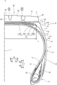
そして、図1及び図2に示すように、バットレス部18の外表面には、接地端Eからタイヤ径方向内側Riへ延びる傾斜部48と、傾斜部48よりタイヤ径方向内側に設けられたえぐり部50とが形成されている。
Then, as shown in FIGS. 1 and 2, on the outer surface of the
傾斜部48は、接地端Eからタイヤ径方向内側Riへ行くほどタイヤ幅方向外側Woへ広がるように(つまり、タイヤ径方向外側Woに行くほど縮径するように)傾斜している。この傾斜部48は、ショルダー陸部42の接地端E側の剛性を弱めて轍などの路面の段差を乗り越える際のワンダリング性能を向上させる。
The
なお、本実施形態では、図2に示すように、傾斜部48の先端側(タイヤ幅方向外側)はタイヤ径方向内側Riに向かって折れ曲がった屈曲部49が設けられ、屈曲部49の先端にえぐり部50のタイヤ径方向外側端50aが接続されている。
In the present embodiment, as shown in FIG. 2, a
えぐり部50は、バットレス部18の外表面よりタイヤ幅方向内側Wiへ向けて陥没するタイヤ周方向に延びる凹溝である。好ましくは、えぐり部50の底面の少なくとも一部が、えぐり部50のタイヤ径方向外側端50aからタイヤ径方向内側Riへ延びる直線sよりタイヤ幅方向内側Wiに位置するように、えぐり部50は、バットレス部18の外表面よりタイヤ幅方向内側Wiへ向けて陥没する。
えぐり部50の底面の断面形状は、曲率半径の異なる複数の円弧を、タイヤ径方向外側Roから内側Riに行くほど曲率半径の小さくなるように配置し、隣接する円弧が共通の接線を持つ接点において接続された曲線形状をなしている。
The gouged
The cross-sectional shape of the bottom surface of the gouged
具体的に、えぐり部50の底面は、タイヤ径方向外側Roに設けられた上側円弧部51aと、上側円弧部51aのタイヤ径方向内側Riに設けられた下側円弧部51bとからなる。上側円弧部51aは、断面が曲率半径raの円弧からなる曲面であり、下側円弧部51bは、断面が曲率半径raより小さい曲率半径rbの円弧からなる曲面である。一例として、上側円弧部51aの断面の曲率半径raを30mm、下側円弧部51bの断面の曲率半径rbを6mmに設定することができる。
Specifically, the bottom surface of the gouged
えぐり部50の底面を構成する上側円弧部51a及び下側円弧部51bは、接続部Cにおいて共通の接線を持つように接続されており、接続部Cにおいてえぐり部50の底面からタイヤ幅方向外側Woへ突出する突条が生じることなく滑らかに接続されている。
The
なお、えぐり部50や上側円弧部51aと下側円弧部51bの接続部Cを、バットレス部18の任意の位置に設けることができるが、円弧部51a、51bのうち最もタイヤ径方向内側Riに設けられた下側円弧部51bがタイヤ径方向Rにおいてベルト26の端部の少なくとも一部と重なるように、言い換えれば、下側円弧部51bのタイヤ幅方向内側Wiにベルト26の端部の少なくとも一部が位置するように、えぐり部50を配置することが好ましい。より好ましくは、図2に示すように、上側円弧部51aと下側円弧部51bの接続部Cが、最もタイヤ径方向外側Roに位置する第4ベルト26Dの端部とタイヤ径方向Rにおいて重なるようにえぐり部50を配置する。
The connection portion C between the
また、タイヤ幅方向中央部(つまり、タイヤ赤道面CL)から最も幅広の第2ベルト26Bのタイヤ幅方向端までの長さLに対する、タイヤ赤道面CLから上側円弧部51aと下側円弧部51bとの接続部Cまでの長さMの比率p(=M/L)が1.03以上1.11以下であることが好ましい。比率pを1.03以上とすることで、ベルト26の端部からえぐり部50の底面までゴム厚みを十分に確保することができ、ベルト26の端部からトレッドゴムが剥離しにくくなる。また、比率pを1.11以下とすることで、えぐり部50の陥没量を十分に確保することができ、接地端E近傍における接地圧を低減することができる。
Further, the
また、えぐり部50のタイヤ径方向外側端50aに接する接線nは、タイヤ径方向Rに対してタイヤ幅方向内側Wiに傾斜しており、タイヤ径方向Rに対する角度θが10度より大きく35度未満であることが好ましい。角度θを10度より大きく設定することで、えぐり部50の陥没量を十分に確保することができ、接地端E近傍における接地圧を低減することができる。また、角度θを35度より小さく設定することで、トレッド部16の接地端E近傍で受けた荷重により生じる歪みがえぐり部50の底面に形成された接続部Cに集中しにくくなりクラック発生を抑えることができる。
Further, the tangent line n in contact with the tire radial
なお、本明細書における上記各寸法は、特に言及した場合を除いて、空気入りタイヤを正規リムに装着して正規内圧を充填した無負荷の正規状態でのものである。また、本明細書において、接地端Eとは、空気タイヤを正規リムにリム組みし、正規内圧を充填した状態で平坦な路面に垂直に置き、正規荷重を加えた正規荷重状態において、路面に接地するトレッド面のタイヤ幅方向端部のことである。 Unless otherwise specified, the above-mentioned dimensions in the present specification are in a normal state with no load, in which a pneumatic tire is mounted on a normal rim and filled with a normal internal pressure. Further, in the present specification, the ground contact end E means that the pneumatic tire is rim-assembled on a regular rim, placed vertically on a flat road surface with a regular internal pressure applied, and on the road surface under a regular load state to which a regular load is applied. It is the end of the tread surface that touches the ground in the tire width direction.
正規リムとは、タイヤが基づいている規格を含む規格体系において、当該規格がタイヤ毎に定めるリムであり、例えばJATMAであれば標準リム、TRAであれば"Design Rim"、ETRTOであれば"MeasuringRim"となる。正規内圧とは、タイヤが基づいている規格を含む規格体系において、各規格がタイヤ毎に定めている空気圧であり、JATMAであれば最高空気圧、TRAであれば表"TIRE LOAD LIMITS AT VARIOUS COLD INFLATION PRESSURES"に記載の最大値、ETRTOであれば"INFLATION PRESSURE"である。例えば、タイヤサイズが295/75R22.5(LR=G)である場合には760kPaとすることができる。また、正規荷重とは、タイヤが基づいている規格を含む規格体系において、各規格がタイヤ毎に定めている荷重であり、JATMAであれば最大負荷能力、TRAであれば上記の表に記載の最大値、ETRTOであれば"LOAD CAPACITY"であるが、タイヤが乗用車用である場合には前記荷重の88%に相当する荷重とする。 A regular rim is a rim defined for each tire in the standard system including the standard on which the tire is based. For example, if it is JATTA, it is a standard rim, if it is TRA, it is "Design Rim", and if it is ETRTO, " It becomes "Measuring Rim". The regular internal pressure is the air pressure defined for each tire in the standard system including the standard on which the tire is based. For JATTA, the maximum air pressure, and for TRA, the table "TIRE LOAD LIMITS AT VARIOUS COLD INFLATION" The maximum value described in "PRESSURES", or "INFLATION PRESSURE" for ETRTO. For example, when the tire size is 295 / 75R22.5 (LR = G), it can be set to 760 kPa. The normal load is the load defined for each tire in the standard system including the standard on which the tire is based. If it is JATTA, it is the maximum load capacity, and if it is TRA, it is described in the above table. If the maximum value is ETRTO, it is "LOAD CAPACITY", but if the tires are for passenger cars, the load is equivalent to 88% of the above load.
以上のような本実施形態の空気入りタイヤ10では、バットレス部18にタイヤ幅方向内側Wiへ向けて陥没するえぐり部50が設けられているため、トレッド部16の接地端E近傍の剛性を低下させて、接地端E近傍における接地性の向上(接地面全体の接地圧力分布の均一化)を図ることができ、偏摩耗の発生を抑えることができる。
In the
しかも、えぐり部50の底面は上側円弧部51aと下側円弧部51bから構成され、えぐり部50の底面の断面形状が、曲率半径の異なる複数の円弧を、タイヤ径方向外側Roから内側Riに行くほど曲率半径が小さくなるように配置し、隣接する円弧が共通の接線を持つ接点において接続された曲線形状をなしている。そのため、空気入りタイヤ10では、トレッド部16の接地端E近傍で受けた荷重により生じる歪みをえぐり部50の広い範囲に分散することができ、タイヤ耐久性を向上させることができる。
Moreover, the bottom surface of the gouged
また、本実施形態の空気入りタイヤ10では、円弧部51、52のうち最もタイヤ径方向内側Riに設けられた下側円弧部51bが、タイヤ径方向Rにおいてベルト26の端部と重なっている。これにより、曲率半径が小さく撓み変形しやすい下側円弧部51bのタイヤ幅方向内側Wiにベルト26の端部が位置し、下側円弧部51bにおける撓み変形を適度に規制して、えぐり部50全体で撓みやすさを均一化することができる。そのため、トレッド部16の接地端E近傍で受けた荷重により生じる歪みがえぐり部50全体に分散されやすくなり、より一層タイヤ耐久性を向上させることができる。
しかも、上側円弧部51aと下側円弧部51bの接続部Cが第4ベルト26Dの端部とタイヤ径方向Rにおいて重なるようにえぐり部50がバットレス部18に設けられているため、特に撓み変形が生じやすい下側円弧部51bの接続部C近傍において変形を規制することができ、より一層えぐり部50全体に均一に歪みが分散されやすくなり、タイヤ耐久性を向上させることができる。
Further, in the
Moreover, since the gouged
(第2実施形態)
次に、本発明の第2実施形態について図3及び図4を参照して説明する。なお、第1実施形態と同一の部分には説明は省略し、異なる部分について説明する。
(Second Embodiment)
Next, the second embodiment of the present invention will be described with reference to FIGS. 3 and 4. The same parts as those in the first embodiment will be omitted, and different parts will be described.
本実施形態では、バットレス部18に設けられたえぐり部50のタイヤ径方向内側Riからタイヤ最大幅位置Pまでの間に複数の突条61、62、63、64と、これらの突条61、62、63、64によって区画形成された凹部71、72、73、74が設けられている。
In the present embodiment, a plurality of
なお、タイヤ最大幅位置Pとは、タイヤ幅方向Wにおいてサイドウォール部14の表面の最も外側にある位置であり、タイヤ最大幅をとるサイドウォール部表面上の位置である。タイヤ最大幅は、断面幅とも称され、サイドウォール部表面の模様や文字等の突起を除いた幅である。
The maximum tire width position P is a position on the outermost surface of the
複数の突条61、62、63、64は、バットレス部18の外表面からタイヤ幅方向外側Woへ突出しタイヤ周方向に沿って延びる互いに略平行に設けられた突起である。
The plurality of
最もタイヤ径方向外側Roに設けられた第1突条61は、えぐり部50のタイヤ径方向内側端50bとの間に、タイヤ周方向に沿って延びる第1凹部71を形成する。第1凹部71は、断面形状が曲率半径r1の円弧形状の底面を有している。
The
第2突条62は、タイヤ径方向外側Roに隣接する第1突条61との間に、タイヤ周方向に沿って延びる第2凹部72を形成する。第2凹部72は、断面形状が曲率半径r2の円弧形状の底面を有している。
The
第3突条63は、タイヤ径方向外側Roに隣接する第2突条62との間に、タイヤ周方向に沿って延びる第3凹部73を形成する。第3凹部73は、断面形状が曲率半径r3の円弧形状の底面を有している。
The
第4突条64は、タイヤ径方向外側Roに隣接する第3突条63との間に、タイヤ周方向に沿って延びる第4凹部74を形成する。第4凹部74は、断面形状が曲率半径r4の円弧形状の底面を有している。
The
第1凹部71、第2凹部72、第3凹部73及び第4凹部74は、タイヤ周方向に沿って互いに略平行に、かつ、第1凹部71からタイヤ径方向内側Riへ向けてこの順番でタイヤ径方向Rに並べて設けられている。
The
また、第1凹部71、第2凹部72及び第3凹部73の底面を構成する円弧の曲率半径r1,r2,r3は、タイヤ径方向内側riに位置する凹部ほど漸次大きくなっており(つまり、r1<r2<r3)、第4凹部74の底面を構成する曲率半径r4が第3凹部73の底面を構成する円弧の曲率半径r3と同じ大きさに設定されている。
Further, the radii of curvature r1, r2, r3 of the arcs constituting the bottom surfaces of the
本実施形態では、えぐり部50のタイヤ径方向内側Riからタイヤ最大幅位置Pまでの間に、複数の突条61、62、63、64によって区画形成されたタイヤ周方向に沿って延びる凹部71、72、73、74が設けられているため、トレッド部16の接地端E近傍で受けた荷重により発生する歪みを、えぐり部50だけでなく凹部71、72、73、74にも分散させることができ、トレッド部の接地端近傍における偏摩耗の発生を抑えつつタイヤ耐久性を向上することができる。
In the present embodiment, a
しかも、本実施形態では、タイヤ径方向内側Riに位置する凹部ほど底面の断面形状が曲率半径の大きい円弧形状をなしており、バットレス部18の形状がタイヤ径方向Rに滑らかに変化するため、視覚的な違和感を抑えつつバットレス部18にえぐり部50及び複数の凹部71、72、73、74を設けることができる。
Moreover, in the present embodiment, the concave portion located on the inner side Ri in the tire radial direction has an arc shape having a larger radius of curvature on the bottom surface, and the shape of the
(変更例)
上記の実施形態は、例として提示したものであり、発明の範囲を限定することは意図していない。この新規な実施形態は、その他の様々な形態で実施されることが可能であり、発明の要旨を逸脱しない範囲で、種々の省略、置き換え、変更を行うことができる。
(Change example)
The above embodiments are presented as examples and are not intended to limit the scope of the invention. This novel embodiment can be implemented in various other embodiments, and various omissions, replacements, and changes can be made without departing from the gist of the invention.
例えば、上記した実施形態では、えぐり部50の底面が、曲率半径の異なる2個の円弧からなる場合について説明したが、3個以上の円弧をタイヤ径方向外側から内側に行くほど曲率半径の小さくなるように配置し、隣接する円弧を共通の接線を持つ接点において接続した曲線形状であってもよい。
For example, in the above embodiment, the case where the bottom surface of the gouged
また、えぐり部50は、タイヤ周方向に完全に連続した環状をなすものであっても、周方向の所々で断続しているものであってもよい。
Further, the gouged
また、本発明は、トラック・バス用などのような高荷重用の空気入りタイヤに好適に用いることができるが、これに限らず、乗用車用やライトトラック用などの各種の空気入りタイヤに用いることができる。 Further, the present invention can be suitably used for pneumatic tires for high loads such as for trucks and buses, but the present invention is not limited to this and is used for various pneumatic tires for passenger cars and light trucks. be able to.
10…タイヤ、14…サイドウォール部、16…トレッド部、18…バットレス部、42…ショルダー陸部、48…傾斜部、49…屈曲部、50…えぐり部、50a…タイヤ径方向外側端、50b…タイヤ径方向内側端、51a…上側円弧部、51b…下側円弧部、61…第1突条、62…第2突条、63…第3突条、64…第4突条、71…第1凹部、72…第2凹部、73…第3凹部、74…第4凹部 10 ... tire, 14 ... sidewall part, 16 ... tread part, 18 ... buttless part, 42 ... shoulder land part, 48 ... inclined part, 49 ... bent part, 50 ... gouging part, 50a ... tire radial outer end, 50b ... Inner end in tire radial direction, 51a ... Upper arc portion, 51b ... Lower arc portion, 61 ... 1st ridge, 62 ... 2nd ridge, 63 ... 3rd ridge, 64 ... 4th ridge, 71 ... 1st recess, 72 ... 2nd recess, 73 ... 3rd recess, 74 ... 4th recess
Claims (8)
前記えぐり部のタイヤ径方向外側端から前記えぐり部のタイヤ径方向内側端までの断面形状は、曲率半径の異なる複数の円弧を、タイヤ径方向外側から内側に行くほど曲率半径が小さくなるように配置し、隣接する円弧が共通の接線を持つ接点において接続された曲線形状をなしている空気入りタイヤ。 It is provided with a tread portion, a sidewall portion, a buttress portion provided between the tread portion and the sidewall portion, and a hollow portion recessed inward in the tire width direction from the outer surface of the buttress portion.
The cross-sectional shape from the outer end of the gouge in the tire radial direction to the inner end of the gouge in the tire radial direction is such that a plurality of arcs having different radiuses of curvature are formed so that the radius of curvature becomes smaller from the outer side to the inner side in the radial direction of the tire. Pneumatic tires that are placed and have a curved shape with adjacent arcs connected at contacts with a common tangent.
前記えぐり部のタイヤ径方向外側端から前記えぐり部のタイヤ径方向内側端までにおいて最も曲率半径が小さい円弧からなる部分が、前記タイヤ径方向で前記ベルトの端部の少なくとも一部と重なる位置に形成されている請求項1に記載の空気入りタイヤ。 Equipped with a belt on the tread
At a position where the portion formed by the arc having the smallest radius of curvature from the tire radial outer end of the gouged portion to the tire radial inner end of the gouged portion overlaps at least a part of the end portion of the belt in the tire radial direction. The pneumatic tire formed according to claim 1.
前記えぐり部のタイヤ径方向外側端から前記えぐり部のタイヤ径方向内側端までの断面形状は、曲率半径の異なる2つの円弧が接続部において接続された曲線形状をなしており、
タイヤ幅方向中央から前記ベルトにおいて最もタイヤ幅方向外側に位置するベルト端までの長さLに対する、タイヤ幅方向中央から前記接続部までの長さMの比率M/Lが、1.03以上1.11以下である請求項1~5のいずれか1項に記載の空気入りタイヤ。 A belt is provided on the tread portion.
The cross-sectional shape from the tire radial outer end of the gouged portion to the tire radial inner end of the gouged portion is a curved shape in which two arcs having different radii of curvature are connected at the connecting portion .
The ratio M / L of the length M from the center in the tire width direction to the connection portion with respect to the length L from the center in the tire width direction to the belt end located on the outermost side in the tire width direction of the belt is 1.03 or more. The pneumatic tire according to any one of claims 1 to 5, which is 11.1 or less.
Priority Applications (3)
| Application Number | Priority Date | Filing Date | Title |
|---|---|---|---|
| JP2018124949A JP7081999B2 (en) | 2018-06-29 | 2018-06-29 | Pneumatic tires |
| CN201910489120.5A CN110654169A (en) | 2018-06-29 | 2019-06-06 | Pneumatic tire |
| US16/453,241 US20200001652A1 (en) | 2018-06-29 | 2019-06-26 | Pneumatic tire |
Applications Claiming Priority (1)
| Application Number | Priority Date | Filing Date | Title |
|---|---|---|---|
| JP2018124949A JP7081999B2 (en) | 2018-06-29 | 2018-06-29 | Pneumatic tires |
Publications (2)
| Publication Number | Publication Date |
|---|---|
| JP2020001617A JP2020001617A (en) | 2020-01-09 |
| JP7081999B2 true JP7081999B2 (en) | 2022-06-07 |
Family
ID=69028850
Family Applications (1)
| Application Number | Title | Priority Date | Filing Date |
|---|---|---|---|
| JP2018124949A Active JP7081999B2 (en) | 2018-06-29 | 2018-06-29 | Pneumatic tires |
Country Status (3)
| Country | Link |
|---|---|
| US (1) | US20200001652A1 (en) |
| JP (1) | JP7081999B2 (en) |
| CN (1) | CN110654169A (en) |
Families Citing this family (5)
| Publication number | Priority date | Publication date | Assignee | Title |
|---|---|---|---|---|
| JP7202458B2 (en) * | 2019-05-20 | 2023-01-11 | 三菱重工機械システム株式会社 | Tire electrical resistance measuring device, electrical resistance probe |
| JP7347745B2 (en) * | 2019-12-06 | 2023-09-20 | Toyo Tire株式会社 | pneumatic tires |
| JP7315846B2 (en) * | 2020-01-21 | 2023-07-27 | 横浜ゴム株式会社 | pneumatic tire |
| JP7024824B2 (en) * | 2020-07-03 | 2022-02-24 | 住友ゴム工業株式会社 | tire |
| CN112013938A (en) * | 2020-09-04 | 2020-12-01 | 北京因泰智行科技有限公司 | Vehicle load detection method and vehicle |
Citations (1)
| Publication number | Priority date | Publication date | Assignee | Title |
|---|---|---|---|---|
| WO2008026600A1 (en) | 2006-08-28 | 2008-03-06 | Bridgestone Corporation | Pneumatic tire |
Family Cites Families (11)
| Publication number | Priority date | Publication date | Assignee | Title |
|---|---|---|---|---|
| JPH02133202A (en) * | 1988-11-11 | 1990-05-22 | Bridgestone Corp | Pneumatic tire for heavy load |
| JP2544532B2 (en) * | 1990-06-15 | 1996-10-16 | 住友ゴム工業株式会社 | Heavy duty tires |
| JP3570182B2 (en) * | 1997-11-21 | 2004-09-29 | 東洋ゴム工業株式会社 | Heavy duty pneumatic tires |
| JP2001158208A (en) * | 1999-12-01 | 2001-06-12 | Bridgestone Corp | Pneumatic tire |
| WO2003059654A1 (en) * | 2002-01-16 | 2003-07-24 | Sumitomo Rubber Industries, Ltd. | Heavy duty tire |
| KR100792973B1 (en) * | 2006-09-07 | 2008-01-08 | 한국타이어 주식회사 | Pneumatic vehicle tire |
| JP2009056955A (en) * | 2007-08-31 | 2009-03-19 | Bridgestone Corp | Pneumatic tire for heavy load |
| JP4934178B2 (en) * | 2009-09-04 | 2012-05-16 | 住友ゴム工業株式会社 | Heavy duty pneumatic tire |
| JP5576994B2 (en) * | 2012-01-24 | 2014-08-20 | 株式会社ブリヂストン | Pneumatic tire |
| DE102014216798A1 (en) * | 2014-08-22 | 2016-02-25 | Continental Reifen Deutschland Gmbh | Vehicle tires |
| DE102014218662A1 (en) * | 2014-09-17 | 2016-03-31 | Continental Reifen Deutschland Gmbh | Vehicle tires |
-
2018
- 2018-06-29 JP JP2018124949A patent/JP7081999B2/en active Active
-
2019
- 2019-06-06 CN CN201910489120.5A patent/CN110654169A/en active Pending
- 2019-06-26 US US16/453,241 patent/US20200001652A1/en not_active Abandoned
Patent Citations (1)
| Publication number | Priority date | Publication date | Assignee | Title |
|---|---|---|---|---|
| WO2008026600A1 (en) | 2006-08-28 | 2008-03-06 | Bridgestone Corporation | Pneumatic tire |
Also Published As
| Publication number | Publication date |
|---|---|
| US20200001652A1 (en) | 2020-01-02 |
| JP2020001617A (en) | 2020-01-09 |
| CN110654169A (en) | 2020-01-07 |
Similar Documents
| Publication | Publication Date | Title |
|---|---|---|
| JP7081999B2 (en) | Pneumatic tires | |
| JP5024485B1 (en) | Pneumatic tire | |
| WO2009139182A1 (en) | Pneumatic tire | |
| EP1484196B1 (en) | Tire tread contour | |
| JP4973810B1 (en) | Pneumatic tire | |
| JP2010280322A (en) | Pneumatic tire | |
| JP5467081B2 (en) | Pneumatic tire | |
| US20230068330A1 (en) | Pneumatic tire | |
| WO2013054684A1 (en) | Pneumatic tire | |
| JP6300342B2 (en) | Run flat tire | |
| JP2009184371A (en) | Pneumatic tire | |
| JP2010116065A (en) | Pneumatic tire | |
| JP2013199266A (en) | Pneumatic tire | |
| JP6728795B2 (en) | Pneumatic tire | |
| JP7482622B2 (en) | Pneumatic tires | |
| JP7485907B2 (en) | Pneumatic tires | |
| JP2019094025A (en) | Pneumatic tire | |
| JP6828442B2 (en) | Pneumatic tires | |
| JP7347745B2 (en) | pneumatic tires | |
| US11420482B2 (en) | Pneumatic tire | |
| JP7343769B2 (en) | pneumatic tires | |
| JP7124553B2 (en) | pneumatic tire | |
| JP2004359030A (en) | Pneumatic tire | |
| JP5275655B2 (en) | Pneumatic tire | |
| JP2024083808A (en) | Pneumatic tire |
Legal Events
| Date | Code | Title | Description |
|---|---|---|---|
| A621 | Written request for application examination |
Free format text: JAPANESE INTERMEDIATE CODE: A621 Effective date: 20210414 |
|
| A977 | Report on retrieval |
Free format text: JAPANESE INTERMEDIATE CODE: A971007 Effective date: 20220217 |
|
| A131 | Notification of reasons for refusal |
Free format text: JAPANESE INTERMEDIATE CODE: A131 Effective date: 20220222 |
|
| A521 | Request for written amendment filed |
Free format text: JAPANESE INTERMEDIATE CODE: A523 Effective date: 20220328 |
|
| TRDD | Decision of grant or rejection written | ||
| A01 | Written decision to grant a patent or to grant a registration (utility model) |
Free format text: JAPANESE INTERMEDIATE CODE: A01 Effective date: 20220524 |
|
| A61 | First payment of annual fees (during grant procedure) |
Free format text: JAPANESE INTERMEDIATE CODE: A61 Effective date: 20220526 |
|
| R150 | Certificate of patent or registration of utility model |
Ref document number: 7081999 Country of ref document: JP Free format text: JAPANESE INTERMEDIATE CODE: R150 |