EP2291875B1 - Battery straps - Google Patents
Battery straps Download PDFInfo
- Publication number
- EP2291875B1 EP2291875B1 EP09774325.6A EP09774325A EP2291875B1 EP 2291875 B1 EP2291875 B1 EP 2291875B1 EP 09774325 A EP09774325 A EP 09774325A EP 2291875 B1 EP2291875 B1 EP 2291875B1
- Authority
- EP
- European Patent Office
- Prior art keywords
- battery
- cell
- cells
- straps
- strap
- Prior art date
- Legal status (The legal status is an assumption and is not a legal conclusion. Google has not performed a legal analysis and makes no representation as to the accuracy of the status listed.)
- Active
Links
Images

Classifications
-
- H—ELECTRICITY
- H01—ELECTRIC ELEMENTS
- H01M—PROCESSES OR MEANS, e.g. BATTERIES, FOR THE DIRECT CONVERSION OF CHEMICAL ENERGY INTO ELECTRICAL ENERGY
- H01M50/00—Constructional details or processes of manufacture of the non-active parts of electrochemical cells other than fuel cells, e.g. hybrid cells
- H01M50/50—Current conducting connections for cells or batteries
- H01M50/502—Interconnectors for connecting terminals of adjacent batteries; Interconnectors for connecting cells outside a battery casing
-
- H—ELECTRICITY
- H01—ELECTRIC ELEMENTS
- H01M—PROCESSES OR MEANS, e.g. BATTERIES, FOR THE DIRECT CONVERSION OF CHEMICAL ENERGY INTO ELECTRICAL ENERGY
- H01M50/00—Constructional details or processes of manufacture of the non-active parts of electrochemical cells other than fuel cells, e.g. hybrid cells
- H01M50/50—Current conducting connections for cells or batteries
- H01M50/528—Fixed electrical connections, i.e. not intended for disconnection
- H01M50/529—Intercell connections through partitions, e.g. in a battery casing
-
- H—ELECTRICITY
- H01—ELECTRIC ELEMENTS
- H01M—PROCESSES OR MEANS, e.g. BATTERIES, FOR THE DIRECT CONVERSION OF CHEMICAL ENERGY INTO ELECTRICAL ENERGY
- H01M50/00—Constructional details or processes of manufacture of the non-active parts of electrochemical cells other than fuel cells, e.g. hybrid cells
- H01M50/10—Primary casings, jackets or wrappings of a single cell or a single battery
- H01M50/102—Primary casings, jackets or wrappings of a single cell or a single battery characterised by their shape or physical structure
- H01M50/112—Monobloc comprising multiple compartments
-
- Y—GENERAL TAGGING OF NEW TECHNOLOGICAL DEVELOPMENTS; GENERAL TAGGING OF CROSS-SECTIONAL TECHNOLOGIES SPANNING OVER SEVERAL SECTIONS OF THE IPC; TECHNICAL SUBJECTS COVERED BY FORMER USPC CROSS-REFERENCE ART COLLECTIONS [XRACs] AND DIGESTS
- Y02—TECHNOLOGIES OR APPLICATIONS FOR MITIGATION OR ADAPTATION AGAINST CLIMATE CHANGE
- Y02E—REDUCTION OF GREENHOUSE GAS [GHG] EMISSIONS, RELATED TO ENERGY GENERATION, TRANSMISSION OR DISTRIBUTION
- Y02E60/00—Enabling technologies; Technologies with a potential or indirect contribution to GHG emissions mitigation
- Y02E60/10—Energy storage using batteries
Definitions
- the present disclosure relates to batteries (e.g., lead-acid batteries for use as automotive, commercial, industrial, and marine batteries in starting, lighting, and ignition (“SLI”) and other applications).
- batteries e.g., lead-acid batteries for use as automotive, commercial, industrial, and marine batteries in starting, lighting, and ignition (“SLI”) and other applications.
- SLI starting, lighting, and ignition
- the present disclosure more specifically relates to batteries and internal electrical connections in batteries.
- a battery having one or more battery cell elements in a wound configuration e.g., spiral wound or jelly roll
- a wound configuration e.g., spiral wound or jelly roll
- Such known batteries typically include a variety of shapes and configurations. In batteries with multiple coiled cell elements, the cells are connected in series by conductive straps requiring substantial additional material costs and weight.
- such known batteries do not realize certain advantageous features and/or combinations of features.
- JP 2004 265 830 A relates to a battery comprising first and second rows of battery cells.
- the present invention relates to a battery as defined in independent claim 1.
- the inventive battery comprises six battery cells in a two by three pattern with three cells located on either side of a dividing line wherein the cells are electrically coupled in series by five straps and wherein no more than two of the straps cross the dividing line.
- the battery comprises a first row of three battery cells and a second low of three battery cells wherein the cells of the first row are electrically coupled in series by two battery straps and wherein the first and second cells in the second row are electrically coupled by a battery strap and wherein a strap couples one of the first or second cells in the second row is electrically coupled to a cell in the first row and wherein a strap electrically couples the third cell of the second row to a cell of the first row and wherein the battery cells are electrically coupled in senses by the straps.
- the present disclosure improves battery performance and/or reduces weight and cost.
- the present disclosure relates to a method and apparatus for connecting battery cells in series using straps with reduced overall size and electrical resistance compared to conventional battery straps.
- the straps and configuration thereof according to various exemplary embodiments provide a more efficient electrical path and/or use less material than conventional battery straps.
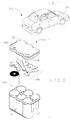
- a vehicle 130 that includes a battery 100 according to an exemplary embodiment. While vehicle 130 is shown as an automobile, according to various alternative embodiments, the vehicle may comprise any variety of types of vehicles including, among others, motorcycles, buses, recreational vehicles, boats, and the like. According to an exemplary embodiment, vehicle 130 uses an internal combustion engine for locomotive purposes.
- Battery 100 shown in FIG. 1 is configured to provide at least a portion of the power required to start or operate vehicle 100 and/or various vehicle systems (e.g., SLI). Further, it should be understood that battery 100 may be utilized in a variety of applications not involving vehicle 130, and all such applications are intended to be within the scope of the present disclosure.
- SLI vehicle systems
- the battery may include any type of secondary battery (e.g., rechargeable battery).
- battery 100 includes a lead-acid storage battery.
- lead-acid storage batteries may be either sealed (e.g., non-maintenance) or unsealed (e.g., wet).
- Battery 100 is illustrated in FIG. 2 .
- battery 100 includes a cover 102 and a housing or container 101, one or more battery elements 110, straps 106, and battery terminals 103-104.
- each battery element 110 includes a negative electrode, a positive electrode, and a separator in a wound configuration (e.g., spiral wound or jelly roll).
- the battery cells or elements are electrically coupled in series by straps 106 and battery terminals 103-104 are electrically coupled to the cells at each end of the series.
- Battery 100 is illustrated in FIG. 3 .
- battery 100 includes several cell elements 111-116 provided in compartments defined by a container or housing 101.
- the illustrations provided herein relate to automotive applications, wherein six spiral wound cells are used for producing a standard automotive 12-volt battery. It will be apparent to those skilled in the art after reading this specification that the size and number of the cells used to construct a battery may vary widely, depending upon the desired end use.
- container 101 includes a plurality of housings or cell containers defined by one or more walls. While the figures generally illustrate a container having six cell containers or compartments, a different number of cell containers or compartments may be provided according to other exemplary embodiments. While the figures generally illustrate the cell containers arranged in a symmetrical fashion, it should be appreciated that the cell containers may be arranged in other patterns (e.g., an off-set or staggered pattern).
- each cell container is configured to substantially contain therein a cell element of battery 100.
- the cell element may be a wound cell element that includes a positive electrode, a negative electrode, and a separator such as an absorbent glass mat ("AGM") separator provided between the positive and negative electrode.
- AGM absorbent glass mat
- the electrodes and the separator are wound or wrapped in a spiral, and acid (e.g., sulfuric acid) may be provided in the cell container.
- the each container or compartment has a generally cylindrical configuration.
- one or more cell containers may have other configurations (e.g., a "tapered" shape having a different diameter at one of the bottom or top of the cell container, an "hourglass” shape, etc.).
- One or more of the cell containers or compartments may also have features formed on the bottoms thereof (i.e. the closed ends).
- container 101 also includes a base.
- the base is integrally formed with container 101.
- the base is produced separately and coupled to the container.
- FIG. 3 also shows cast-on-straps 121-125 which includes an elongated body portion of a length sufficient to electrically couple each turn in a coil (e.g., via lugs (not shown) extending upwardly from the coil).
- FIG. 2 also illustrates a cast-on-strap coupling lugs to a negative terminal.
- molten lead is poured into a mold containing a portion of the battery cell coils (e.g., the lugs) to which the lead adheres as it cools and hardens.
- a plurality of individual electrochemical cells or elements 111-116 are disposed within the cell containers of battery 100.
- the elements 111-116 are preferably generally cylindrical in form.
- elements 111-116 and the cell containers or compartments are arranged in two substantially parallel rows of three.
- Cell elements 111-116 are electrically coupled in series by electrically conducting straps or strap members 121-125.
- the terminals are electrically coupled to cell elements 111-116 by end straps 126-127.
- Certain channels are positioned between the cell containers or compartments to allow strap members 121-125 to be nested below the top of the container.
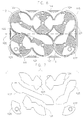
- FIG. 4 illustrates an embodiment of a portion of prior art six-cell battery 200.
- FIG. 5 shows straps 221-225 from the battery of FIG. 4 .
- the size, shape, and configuration of straps 221-225 each affects the cost/or and performance of battery 200.
- the cost of materials, including straps 221-225, is a significant portion of the battery's cost.
- Straps 221-225 also contribute to the weight of battery 200. Straps 221-225 form part of the path for internal current flow.
- the total path length affects total resistance and, thus, the performance of battery 200. Therefore, it would be advantageous to reduce the size and weight of straps 221-225.
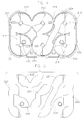
- FIG. 6 illustrates one exemplary configuration of strap members 121-125, end straps 126-127, cell containers, and cell elements 111-116.
- FIG. 7 shows the straps 121-125 from the battery of FIG. 6 .
- a first strap 121 electrically couples a first element 111 to a second element 112
- a second strap member 122 electrically couples second element 112 to a third element 113
- a third strap member 123 electrically couples third element 113 to a fourth element 114
- a fourth strap member 124 electrically couples fourth element 114 to a fifth element 115
- a fifth strap member 125 electrically couples fifth element 115 to a sixth element 116.
- a first end strap 126 electrically couples the first terminal post to first element 111 and a second end strap 127 electrically couples the second terminal post to sixth element 116.
- Strap members 121-125 and end straps 126-127 may be utilized in any number of configurations.
- strap members 121-125 may electrically couple sixth element 116 to second element 112, second element 112 to fifth element 115, fifth element 115 to fourth element 114, fourth element 114 to third element 113, and third element 113 to first element 111.
- strap members 121-125 may connect third element 113 to fourth element 114, fourth element 114 to first element 111, first element 111 to second element 112, second element 112 to sixth element 116, and sixth element 116 to fifth element 115.
- strap members 121-125 may electrically couple fifth element 115 to fourth element 114, fourth element 114 to sixth element 116, sixth element 116 to second element 112, second element 112 to first element 111, and first element 111 to third element 113.
- the battery e.g. configuration of strap members illustrated in FIGS. 6-7
- the battery uses at least about 13 percent less material than the battery (e.g. configuration of strap members) illustrated in FIGS 4-5 .
- the battery e.g. configuration of strap members illustrated in FIGS. 6-7
- the battery 100 including six battery cells symmetrically arranged in a 2x3 pattern.
- the battery may be seen as comprising two sections, each containing three full battery cell elements (illustrated in FIG. 6 by dividing line 105).
- no more than two of five strap members 121-125 cross dividing line 105.
- dividing line 105 is crossed by second strap member 122 and fifth strap member 125, but not by first strap member 121, third strap member 123, or fourth strap member 124.
- the straps that do or do not cross dividing line 105 may differ, but no more than two straps cross dividing line 105 according to various exemplary embodiments.
- each battery cell element is directly adjacent to two or three other cell elements and diagonally adjacent to one or two other cell elements (e.g., first cell element 111 is directly adjacent to second cell element 112 and third cell element 113 and diagonally adjacent to fourth cell element 114; second cell element 112 is directly adjacent to first cell element 111, fourth cell element 114, and sixth cell element 116 and diagonally adjacent to third cell element 113 and fifth cell element 115; etc.).
- there are five battery straps with four of the battery straps electrically coupling directly adjacent cell elements and one battery strap electrically coupling diagonally adjacent cell elements. For example, in the embodiment of FIG.
- second strap member 122 electrically couples diagonally adjacent second cell element 112 and third cell element 113 while first strap member 111 electrically couples first cell element 111 to second cell element 112, third strap member 113 electrically couples third cell element 113 to fourth cell element 114, fourth strap member 114 electrically couples fourth cell element 114 to fifth cell element 115, and fifth strap member 115 electrically couples fifth cell element 115 to sixth cell element 116.
- strap members other than the second strap member 112 may be used to electrically couple diagonally adjacent cell members.
- a first terminal post 103 and a second terminal post 104 extend from the top surface of the cover 102.
- the first terminal post 103 and the second terminal post 104 extend from the top surface of the cover 102 and are positioned substantially near margins of the cover 102.
- the first terminal post 103 and second terminal post 104 are positioned in areas substantially near the intersections of either the front edge or back edge (both of the terminals 103 and 104 are near the same edge) with the first end and second end.
- the various elements of the battery, the battery housing, the battery cover, and the cell containers may be made of a wide variety of materials as is well known in the art.
- the cover, container, and/or various components may be made of any polymeric (e.g., polyethylene, polypropylene, a polypropylene containing material, etc.) or composite (e.g., glass-reinforced polymer) material.
- the container may be made of polypropylene-containing material (e.g., pure polypropylene, co-polymers comprising polypropylene, polypropylene with additives, etc.).
- Such polymeric material is relatively resistant to degradation caused by acid (e.g., sulfuric acid) provided within cells of the container.
- the terminal posts, side terminals and connection members may be made of one or more conductive materials (e.g., lead or a material containing lead).
- the strap members 121-125 and end straps 126-127 may be made of one or more conductive materials (e.g., lead or a material containing lead).
- the container 101 includes one or more lips and/or flanges configured for coupling (e.g., heat sealing) to the cover 102.
- the cover 102 includes one or more terminals 103 and/or 104 that are electrically coupled or conductively coupled (e.g., post burned) to the end straps 126 and/or 127.
- the container 101 may also include one or more flanges located on an upper portion of each end of the container.
- the battery 100 may be lifted and/or carried by the flanges rather than the cover 102 to prevent any damage to the seal between the cover 102 and the container 101.
- the container may also include one or more footings located on the lower portion of one or both ends of the container.
- an adapter system may be provided to elevate the battery and improve fitment.
- the term “coupled” means the joining of two members directly or indirectly to one another. Such joining may be stationary in nature or moveable in nature. Such joining may be achieved with the two members or the two members and any additional intermediate members being integrally formed as a single unitary body with one another or with the two members or the two members and any additional intermediate members being attached to one another. Such joining may be permanent in nature or may be removable or releasable in nature.
- the term “electrically coupled” means the joining or connecting or two members directly or indirectly to one another in such a manner that electrical current may flow between the members.
- Such electrical connection may be stationary or movable in nature.
- Such electrical connection may be achieved with the two members or the two members and any additional intermediate members being integrally formed as a single unitary body with one another or with the two members or the two members and any additional intermediate members being attached to one another.
- Such electrical connection may be permanent in nature or may be removable or releasable in nature.
- elements shown as integrally formed may be constructed of multiple parts or elements and/or elements shown as multiple parts may be integrally formed, the operation of interfaces may be reversed or otherwise varied, the length and/or width of the structures and/or members or connections or other elements of the system may be varied, the nature or number of adjustment positions provided between the elements may be varied, the position of elements may be reversed or otherwise varied, and the nature or number of discrete elements or positions may be altered or varied.
- the elements and/or assemblies of the system may be constructed from any of a wide variety of materials that provide sufficient strength or durability, in any of a wide variety of colors, textures, and combinations. Accordingly, all such modifications are intended to be included within the scope of the present invention. Other substitutions, modifications, changes, and omissions may be made in the design, operating conditions, and arrangement of the preferred and other exemplary embodiments without departing from the scope of the present inventions.
Description
- This application claims priority to
US Provisional Application 61/076,948 filed June 30, 2008 - The present disclosure relates to batteries (e.g., lead-acid batteries for use as automotive, commercial, industrial, and marine batteries in starting, lighting, and ignition ("SLI") and other applications). The present disclosure more specifically relates to batteries and internal electrical connections in batteries.
- It is known to provide for a battery having one or more battery cell elements in a wound configuration (e.g., spiral wound or jelly roll) that may be used for SLI and other applications as it is disclosed in
CN 2 614 389 Y orWO 99/36972 A1 -
JP 2004 265 830 A - The present invention relates to a battery as defined in independent claim 1. The inventive battery comprises six battery cells in a two by three pattern with three cells located on either side of a dividing line wherein the cells are electrically coupled in series by five straps and wherein no more than two of the straps cross the dividing line.
- According to an aspect of the present invention, the battery comprises a first row of three battery cells and a second low of three battery cells wherein the cells of the first row are electrically coupled in series by two battery straps and wherein the first and second cells in the second row are electrically coupled by a battery strap and wherein a strap couples one of the first or second cells in the second row is electrically coupled to a cell in the first row and wherein a strap electrically couples the third cell of the second row to a cell of the first row and wherein the battery cells are electrically coupled in senses by the straps.
- These and other features and advantages of various embodiments of systems and methods according to this invention are described in, or are apparent from, the following detailed description of various exemplary embodiments of various devices, structures, and/or methods according to this invention.
- Various exemplary embodiments of the systems and methods according to the present disclosure will be described in detail, with reference to the following figures, wherein:
-
FIG. 1 is an isometric view of a vehicle including a battery according to an exemplary embodiment; -
FIG. 2 is an exploded isometric view of a portion of a battery according to an exemplary embodiment; -
FIG. 3 is an isometric view of a battery according to an exemplary embodiment with cover removed; -
FIG. 4 is a top view of a battery of the prior art with cover removed; -
FIG. 5 is a top view of the cast-on strap shown inFIG. 4 ; -
FIG. 6 is a top view of a battery according to an exemplary embodiment with cover removed; and -
FIG. 7 is a top view of the cast-on strap shown inFIG. 6 . - It should be understood that the drawings are not necessarily to scale. In certain instances, details that are not necessary to the understanding of the invention or render other details difficult to perceive may have been omitted. It should be understood, of course, that the invention is not necessarily limited to the particular embodiments illustrated herein.
- The present disclosure improves battery performance and/or reduces weight and cost. The present disclosure relates to a method and apparatus for connecting battery cells in series using straps with reduced overall size and electrical resistance compared to conventional battery straps. The straps and configuration thereof according to various exemplary embodiments provide a more efficient electrical path and/or use less material than conventional battery straps.
- Referring to
FIG. 1 , avehicle 130 is shown that includes abattery 100 according to an exemplary embodiment. Whilevehicle 130 is shown as an automobile, according to various alternative embodiments, the vehicle may comprise any variety of types of vehicles including, among others, motorcycles, buses, recreational vehicles, boats, and the like. According to an exemplary embodiment,vehicle 130 uses an internal combustion engine for locomotive purposes. -
Battery 100 shown inFIG. 1 is configured to provide at least a portion of the power required to start or operatevehicle 100 and/or various vehicle systems (e.g., SLI). Further, it should be understood thatbattery 100 may be utilized in a variety of applications not involvingvehicle 130, and all such applications are intended to be within the scope of the present disclosure. - The battery may include any type of secondary battery (e.g., rechargeable battery). According to an exemplary embodiment,
battery 100 includes a lead-acid storage battery. Various other embodiments of lead-acid storage batteries may be either sealed (e.g., non-maintenance) or unsealed (e.g., wet).. -
Battery 100, according to an exemplary embodiment, is illustrated inFIG. 2 . In various exemplary embodiments,battery 100 includes acover 102 and a housing orcontainer 101, one ormore battery elements 110,straps 106, and battery terminals 103-104. In various exemplary embodiments, eachbattery element 110 includes a negative electrode, a positive electrode, and a separator in a wound configuration (e.g., spiral wound or jelly roll). The battery cells or elements are electrically coupled in series bystraps 106 and battery terminals 103-104 are electrically coupled to the cells at each end of the series. -
Battery 100, according to an exemplary embodiment, with the cover removed, is illustrated inFIG. 3 . In various embodiments,battery 100 includes several cell elements 111-116 provided in compartments defined by a container orhousing 101. The illustrations provided herein relate to automotive applications, wherein six spiral wound cells are used for producing a standard automotive 12-volt battery. It will be apparent to those skilled in the art after reading this specification that the size and number of the cells used to construct a battery may vary widely, depending upon the desired end use. - In various embodiments,
container 101 includes a plurality of housings or cell containers defined by one or more walls. While the figures generally illustrate a container having six cell containers or compartments, a different number of cell containers or compartments may be provided according to other exemplary embodiments. While the figures generally illustrate the cell containers arranged in a symmetrical fashion, it should be appreciated that the cell containers may be arranged in other patterns (e.g., an off-set or staggered pattern). - In various embodiments, each cell container is configured to substantially contain therein a cell element of
battery 100. The cell element may be a wound cell element that includes a positive electrode, a negative electrode, and a separator such as an absorbent glass mat ("AGM") separator provided between the positive and negative electrode. In various embodiments, the electrodes and the separator are wound or wrapped in a spiral, and acid (e.g., sulfuric acid) may be provided in the cell container. - According to an exemplary embodiment, the each container or compartment has a generally cylindrical configuration. However, one or more cell containers may have other configurations (e.g., a "tapered" shape having a different diameter at one of the bottom or top of the cell container, an "hourglass" shape, etc.). One or more of the cell containers or compartments may also have features formed on the bottoms thereof (i.e. the closed ends).
- In various embodiments,
container 101 also includes a base. According to one exemplary embodiment, the base is integrally formed withcontainer 101. According to another exemplary embodiment, the base is produced separately and coupled to the container. -
FIG. 3 also shows cast-on-straps 121-125 which includes an elongated body portion of a length sufficient to electrically couple each turn in a coil (e.g., via lugs (not shown) extending upwardly from the coil).FIG. 2 also illustrates a cast-on-strap coupling lugs to a negative terminal. In the casting process, molten lead is poured into a mold containing a portion of the battery cell coils (e.g., the lugs) to which the lead adheres as it cools and hardens. - In various embodiments, a plurality of individual electrochemical cells or elements 111-116 are disposed within the cell containers of
battery 100. In various embodiments, the elements 111-116 are preferably generally cylindrical in form. In various embodiments, elements 111-116 and the cell containers or compartments are arranged in two substantially parallel rows of three. Cell elements 111-116 are electrically coupled in series by electrically conducting straps or strap members 121-125. The terminals are electrically coupled to cell elements 111-116 by end straps 126-127. Certain channels are positioned between the cell containers or compartments to allow strap members 121-125 to be nested below the top of the container. -
FIG. 4 illustrates an embodiment of a portion of prior art six-cell battery 200.FIG. 5 shows straps 221-225 from the battery ofFIG. 4 . The size, shape, and configuration of straps 221-225 each affects the cost/or and performance of battery 200. The cost of materials, including straps 221-225, is a significant portion of the battery's cost. Straps 221-225 also contribute to the weight of battery 200. Straps 221-225 form part of the path for internal current flow. The total path length affects total resistance and, thus, the performance of battery 200. Therefore, it would be advantageous to reduce the size and weight of straps 221-225. -
FIG. 6 illustrates one exemplary configuration of strap members 121-125, end straps 126-127, cell containers, and cell elements 111-116.FIG. 7 shows the straps 121-125 from the battery ofFIG. 6 . As shown inFIG. 6 , afirst strap 121 electrically couples afirst element 111 to asecond element 112, asecond strap member 122 electrically couplessecond element 112 to athird element 113, athird strap member 123 electrically couplesthird element 113 to afourth element 114, afourth strap member 124 electrically couplesfourth element 114 to afifth element 115, and afifth strap member 125 electrically couplesfifth element 115 to asixth element 116. In various embodiments, afirst end strap 126 electrically couples the first terminal post tofirst element 111 and asecond end strap 127 electrically couples the second terminal post tosixth element 116. - Strap members 121-125 and end straps 126-127 may be utilized in any number of configurations. For example, strap members 121-125 may electrically couple
sixth element 116 tosecond element 112,second element 112 tofifth element 115,fifth element 115 tofourth element 114,fourth element 114 tothird element 113, andthird element 113 tofirst element 111. - Alternatively, strap members 121-125 may connect
third element 113 tofourth element 114,fourth element 114 tofirst element 111,first element 111 tosecond element 112,second element 112 tosixth element 116, andsixth element 116 tofifth element 115. - In yet another alternative embodiment, strap members 121-125 may electrically couple
fifth element 115 tofourth element 114,fourth element 114 tosixth element 116,sixth element 116 tosecond element 112,second element 112 tofirst element 111, andfirst element 111 tothird element 113. - By electrically coupling cells 111-116 in series in these or similar patterns, the overall efficiency of the
battery 100 is improved and the material needed to electrically couple cells 111-116 is reduced. More specifically, the battery (e.g. configuration of strap members) illustrated inFIGS. 6-7 , uses at least about 13 percent less material than the battery (e.g. configuration of strap members) illustrated inFIGS 4-5 . Furthermore, the battery (e.g. configuration of strap members) illustrated inFIGS. 6-7 , performs at least about 25 percent better than the battery (e.g. configuration of strap members) illustrated inFIGS. 4-5 (performance measured in cold crank amps). - In various exemplary embodiments, as illustrated in
FIG. 6 , thebattery 100 including six battery cells symmetrically arranged in a 2x3 pattern. In such embodiments, the battery may be seen as comprising two sections, each containing three full battery cell elements (illustrated inFIG. 6 by dividing line 105). In various exemplary embodiments, no more than two of five strap members 121-125cross dividing line 105. For example, in the embodiment ofFIG. 6 , dividingline 105 is crossed bysecond strap member 122 andfifth strap member 125, but not byfirst strap member 121,third strap member 123, orfourth strap member 124. In other exemplary embodiments, such as those described above, the straps that do or do not cross dividingline 105 may differ, but no more than two straps cross dividingline 105 according to various exemplary embodiments. - In various exemplary embodiments with six cells in a 2x3 pattern, such as the embodiment of
FIG. 6 , each battery cell element is directly adjacent to two or three other cell elements and diagonally adjacent to one or two other cell elements (e.g.,first cell element 111 is directly adjacent tosecond cell element 112 andthird cell element 113 and diagonally adjacent tofourth cell element 114;second cell element 112 is directly adjacent tofirst cell element 111,fourth cell element 114, andsixth cell element 116 and diagonally adjacent tothird cell element 113 andfifth cell element 115; etc.). In various exemplary embodiments, there are five battery straps with four of the battery straps electrically coupling directly adjacent cell elements and one battery strap electrically coupling diagonally adjacent cell elements. For example, in the embodiment ofFIG. 6 ,second strap member 122 electrically couples diagonally adjacentsecond cell element 112 andthird cell element 113 whilefirst strap member 111 electrically couplesfirst cell element 111 tosecond cell element 112,third strap member 113 electrically couplesthird cell element 113 tofourth cell element 114,fourth strap member 114 electrically couplesfourth cell element 114 tofifth cell element 115, andfifth strap member 115 electrically couplesfifth cell element 115 tosixth cell element 116. In various other exemplary embodiments, strap members other than thesecond strap member 112 may be used to electrically couple diagonally adjacent cell members. - In various exemplary embodiments, a first
terminal post 103 and a secondterminal post 104 extend from the top surface of thecover 102. In various exemplary embodiments, the firstterminal post 103 and the secondterminal post 104 extend from the top surface of thecover 102 and are positioned substantially near margins of thecover 102. In one exemplary embodiment, the firstterminal post 103 and secondterminal post 104 are positioned in areas substantially near the intersections of either the front edge or back edge (both of theterminals - The various elements of the battery, the battery housing, the battery cover, and the cell containers may be made of a wide variety of materials as is well known in the art. For example, the cover, container, and/or various components may be made of any polymeric (e.g., polyethylene, polypropylene, a polypropylene containing material, etc.) or composite (e.g., glass-reinforced polymer) material. For example, the container may be made of polypropylene-containing material (e.g., pure polypropylene, co-polymers comprising polypropylene, polypropylene with additives, etc.). Such polymeric material is relatively resistant to degradation caused by acid (e.g., sulfuric acid) provided within cells of the container. The terminal posts, side terminals and connection members may be made of one or more conductive materials (e.g., lead or a material containing lead).
- The strap members 121-125 and end straps 126-127 may be made of one or more conductive materials (e.g., lead or a material containing lead).
- In various embodiments, the
container 101 includes one or more lips and/or flanges configured for coupling (e.g., heat sealing) to thecover 102. Thecover 102 includes one ormore terminals 103 and/or 104 that are electrically coupled or conductively coupled (e.g., post burned) to the end straps 126 and/or 127. - For shipping and/or handling purposes, the
container 101 may also include one or more flanges located on an upper portion of each end of the container. Thebattery 100 may be lifted and/or carried by the flanges rather than thecover 102 to prevent any damage to the seal between thecover 102 and thecontainer 101. - For purposes of fitment, the container may also include one or more footings located on the lower portion of one or both ends of the container. In addition, an adapter system may be provided to elevate the battery and improve fitment.
- As utilized herein, the terms "approximately," "about," "substantially," and similar terms are intended to have a broad meaning in harmony with the common and accepted usage by those of ordinary skill in the art to which the subject matter of this disclosure pertains. It should be understood by those of skill in the art who review this disclosure that these terms are intended to allow a description of certain features described and claimed without restricting the scope of these features to the precise numerical ranges provided. Accordingly, these terms should be interpreted as indicating that insubstantial or inconsequential modifications or alterations of the subject matter described and claimed are considered to be within the scope of the invention, as recited in the appended claims.
- It should be noted that references to relative positions (e.g., "top" and "bottom") in this description are merely used to identify various elements, as they are oriented in the figures. It should be recognized that the orientation of particular components may vary greatly depending on the application in which they are used.
- For the purpose of this disclosure, the term "coupled" means the joining of two members directly or indirectly to one another. Such joining may be stationary in nature or moveable in nature. Such joining may be achieved with the two members or the two members and any additional intermediate members being integrally formed as a single unitary body with one another or with the two members or the two members and any additional intermediate members being attached to one another. Such joining may be permanent in nature or may be removable or releasable in nature.
- For the purpose of this disclosure, the term "electrically coupled" means the joining or connecting or two members directly or indirectly to one another in such a manner that electrical current may flow between the members. Such electrical connection may be stationary or movable in nature. Such electrical connection may be achieved with the two members or the two members and any additional intermediate members being integrally formed as a single unitary body with one another or with the two members or the two members and any additional intermediate members being attached to one another. Such electrical connection may be permanent in nature or may be removable or releasable in nature.
- It is important to note that the construction and arrangement of the elements of the system, as shown and described in the preferred and other exemplary embodiments, is illustrative only. Although only a few embodiments of the present inventions have been described in detail in this disclosure, those skilled in the art who review this disclosure will readily appreciate that many modifications are possible (e.g., variations in sizes, dimensions, structures, shapes and proportions of the various elements, values of parameters, mounting arrangements, use of materials, colors, orientations, etc.) without materially departing from the novel teachings and advantages of the subject matter recited. For example, elements shown as integrally formed may be constructed of multiple parts or elements and/or elements shown as multiple parts may be integrally formed, the operation of interfaces may be reversed or otherwise varied, the length and/or width of the structures and/or members or connections or other elements of the system may be varied, the nature or number of adjustment positions provided between the elements may be varied, the position of elements may be reversed or otherwise varied, and the nature or number of discrete elements or positions may be altered or varied. It should be noted that the elements and/or assemblies of the system may be constructed from any of a wide variety of materials that provide sufficient strength or durability, in any of a wide variety of colors, textures, and combinations. Accordingly, all such modifications are intended to be included within the scope of the present invention. Other substitutions, modifications, changes, and omissions may be made in the design, operating conditions, and arrangement of the preferred and other exemplary embodiments without departing from the scope of the present inventions.
Claims (4)
- A battery (100) comprising:six battery cells (111, 112, 113, 114, 115, 116) in a two by three pattern withthree cells located on either side of a dividing plane;wherein the cells (111, 112, 113, 114, 115, 116) are electrically coupled in series by five straps (121, 122, 123, 124, 125);wherein no more and no fewer than two of the straps (121, 122, 123, 124, 125) cross the dividing plane,characterized in thatthe straps (121, 122, 123, 124, 125) are cast-on straps which are connected directly to the battery cells (111, 112, 113, 114, 115, 116).
- The battery of Claim 1 further comprising:a first battery terminal (103) electrically coupled to a cell at a first end of the series of electrically coupled cells (111, 112, 113, 114, 115, 116);a second battery terminal (104) electrically coupled to a cell at a second end of the series of electrically coupled cells (11J, 112, 113, 114, 115, 116); andwherein the first terminal (103) and second terminal (104) are both located on the same side of the dividing plane.
- The battery of Claim 2 wherein the battery cells (111, 112, 113, 114, 115, 116) and straps (121, 122, 123, 124, 125) are contained in a housing (101) and the terminals (103, 104) are located proximate to corners of a cover (102) of the housing (101).
- The battery of Claim 1 comprising:a first row of three battery cells (111, 112,113, 114,115, 116);a second row of three battery cells (111, 112, 113, 114, 115, 116);wherein the cells (111, 112, 113, 114, 115, 116) of the first row are electrically coupled in series by two battery straps (121, 122, 123, 124, 125);wherein the first and second cells (111, 112, 113, 114, 115, 116) in the second row are electrically coupled by a battery strap (121, 122, 123, 124, 125);wherein a strap (121, 122, 123, 124, 125) electrically couples one of the first or secondcells (111, 112, 113, 114, 115, 116) in the second row electrically to a cell in the first row;wherein a strap (121, 122, 123, 124, 125) electrically couples the third cell (111, 112, 113, 114, 115, 116) of the second row a cell (111, 112, 113, 114, 115, 116) of the first row; andwherein the battery cells are electrically coupled in series by the straps.
Applications Claiming Priority (2)
| Application Number | Priority Date | Filing Date | Title |
|---|---|---|---|
| US7694808P | 2008-06-30 | 2008-06-30 | |
| PCT/US2009/049231 WO2010002874A1 (en) | 2008-06-30 | 2009-06-30 | Battery straps |
Publications (3)
| Publication Number | Publication Date |
|---|---|
| EP2291875A1 EP2291875A1 (en) | 2011-03-09 |
| EP2291875A4 EP2291875A4 (en) | 2013-04-10 |
| EP2291875B1 true EP2291875B1 (en) | 2016-06-15 |
Family
ID=41466297
Family Applications (1)
| Application Number | Title | Priority Date | Filing Date |
|---|---|---|---|
| EP09774325.6A Active EP2291875B1 (en) | 2008-06-30 | 2009-06-30 | Battery straps |
Country Status (13)
| Country | Link |
|---|---|
| US (1) | US9093689B2 (en) |
| EP (1) | EP2291875B1 (en) |
| JP (3) | JP2011527085A (en) |
| KR (1) | KR20110030653A (en) |
| CN (2) | CN102077391A (en) |
| AU (1) | AU2009267077B2 (en) |
| BR (1) | BRPI0913651B1 (en) |
| CA (1) | CA2726853C (en) |
| MX (1) | MX2010013673A (en) |
| NZ (1) | NZ589684A (en) |
| RU (1) | RU2519839C2 (en) |
| SG (1) | SG177939A1 (en) |
| WO (1) | WO2010002874A1 (en) |
Families Citing this family (6)
| Publication number | Priority date | Publication date | Assignee | Title |
|---|---|---|---|---|
| EP3574535A1 (en) * | 2017-01-27 | 2019-12-04 | CPS Technology Holdings LLC | Battery straps |
| CN117393868A (en) | 2017-06-09 | 2024-01-12 | Cps 科技控股有限公司 | Lead-acid battery |
| US11936032B2 (en) | 2017-06-09 | 2024-03-19 | Cps Technology Holdings Llc | Absorbent glass mat battery |
| DE102018107091A1 (en) * | 2018-03-26 | 2019-09-26 | Deutsche Post Ag | Battery module for a motor vehicle |
| WO2021067774A1 (en) * | 2019-10-04 | 2021-04-08 | Cps Technology Holdings Llc | Spiral wound battery & cell with carbonised fiber mat current collector |
| GB2590615A (en) * | 2019-12-19 | 2021-07-07 | Dyson Technology Ltd | Battery module and battery pack |
Citations (1)
| Publication number | Priority date | Publication date | Assignee | Title |
|---|---|---|---|---|
| JP2004265830A (en) * | 2003-03-04 | 2004-09-24 | Japan Storage Battery Co Ltd | Battery pack |
Family Cites Families (16)
| Publication number | Priority date | Publication date | Assignee | Title |
|---|---|---|---|---|
| US4346151A (en) * | 1980-12-29 | 1982-08-24 | The Gates Rubber Company | Multicell sealed rechargeable battery |
| AU2065183A (en) * | 1982-10-29 | 1984-05-03 | Chloride Group Public Limited Company | Clamp for assembling storage batteries |
| PT77567B (en) * | 1982-10-29 | 1986-03-12 | Chloride Group Plc | Multicell electric storage batteries |
| US4780379A (en) * | 1987-10-06 | 1988-10-25 | Gates Energy Products, Inc. | Multicell recombinant lead-acid battery with vibration resistant intercell connector |
| US5283137A (en) * | 1991-04-29 | 1994-02-01 | Optima Batteries, Inc. | Cover assembly for rechargeable battery |
| US6051336A (en) * | 1998-01-19 | 2000-04-18 | Johnson Controls Technology | Battery case for thin metal film cells |
| US6023146A (en) * | 1998-03-20 | 2000-02-08 | Optima Batteries, Inc. | Battery system electrical connection apparatus and method |
| US6528206B2 (en) * | 2001-01-22 | 2003-03-04 | SOCIEDAD ESPAñOLA DEL ACUMULADOR TUDOR, S.A. | Electric accumulator battery |
| US7045236B1 (en) * | 2001-08-10 | 2006-05-16 | Johnson Controls Technology Company | Heat and gas exchange system for battery |
| JP2004031062A (en) * | 2002-06-25 | 2004-01-29 | Japan Storage Battery Co Ltd | Manufacturing method of battery pack |
| JP2004178831A (en) * | 2002-11-25 | 2004-06-24 | Shin Kobe Electric Mach Co Ltd | Battery pack |
| CN2614389Y (en) * | 2003-04-11 | 2004-05-05 | 江苏双登电源有限公司 | Winding type valve control sealed lead-acid accumulator |
| JP3915919B2 (en) * | 2003-06-18 | 2007-05-16 | 新神戸電機株式会社 | Assembled battery |
| RU2343598C2 (en) * | 2004-03-26 | 2009-01-10 | Мацусита Электрик Индастриал Ко., Лтд. | Lead battery and storage method for lead battery |
| RU52260U1 (en) * | 2005-10-12 | 2006-03-10 | Закрытое акционерное общество "Кузбассэлемент" | ALKALINE BATTERY |
| UA24887U (en) * | 2006-07-26 | 2007-07-25 | Donbas State Machine Building | Device for transportation of hollow articles |
-
2009
- 2009-06-30 CN CN2009801244871A patent/CN102077391A/en active Pending
- 2009-06-30 SG SG2011097375A patent/SG177939A1/en unknown
- 2009-06-30 WO PCT/US2009/049231 patent/WO2010002874A1/en active Application Filing
- 2009-06-30 AU AU2009267077A patent/AU2009267077B2/en active Active
- 2009-06-30 JP JP2011516809A patent/JP2011527085A/en active Pending
- 2009-06-30 BR BRPI0913651A patent/BRPI0913651B1/en active IP Right Grant
- 2009-06-30 RU RU2011103250/07A patent/RU2519839C2/en active
- 2009-06-30 US US12/999,174 patent/US9093689B2/en active Active
- 2009-06-30 EP EP09774325.6A patent/EP2291875B1/en active Active
- 2009-06-30 NZ NZ58968409A patent/NZ589684A/en unknown
- 2009-06-30 CN CN201611095121.4A patent/CN107104221B/en active Active
- 2009-06-30 KR KR20117002374A patent/KR20110030653A/en active Search and Examination
- 2009-06-30 MX MX2010013673A patent/MX2010013673A/en active IP Right Grant
- 2009-06-30 CA CA2726853A patent/CA2726853C/en active Active
-
2014
- 2014-12-18 JP JP2014255902A patent/JP2015079768A/en active Pending
-
2016
- 2016-11-11 JP JP2016220193A patent/JP6463718B2/en active Active
Patent Citations (1)
| Publication number | Priority date | Publication date | Assignee | Title |
|---|---|---|---|---|
| JP2004265830A (en) * | 2003-03-04 | 2004-09-24 | Japan Storage Battery Co Ltd | Battery pack |
Also Published As
| Publication number | Publication date |
|---|---|
| WO2010002874A1 (en) | 2010-01-07 |
| JP6463718B2 (en) | 2019-02-06 |
| CN107104221B (en) | 2021-01-29 |
| BRPI0913651A2 (en) | 2015-10-27 |
| NZ589684A (en) | 2013-11-29 |
| US20110143188A1 (en) | 2011-06-16 |
| EP2291875A1 (en) | 2011-03-09 |
| EP2291875A4 (en) | 2013-04-10 |
| RU2519839C2 (en) | 2014-06-20 |
| SG177939A1 (en) | 2012-02-28 |
| JP2015079768A (en) | 2015-04-23 |
| WO2010002874A8 (en) | 2010-03-11 |
| CA2726853C (en) | 2013-02-26 |
| AU2009267077A1 (en) | 2010-01-07 |
| JP2011527085A (en) | 2011-10-20 |
| CN107104221A (en) | 2017-08-29 |
| JP2017027964A (en) | 2017-02-02 |
| CA2726853A1 (en) | 2010-01-07 |
| MX2010013673A (en) | 2011-02-24 |
| KR20110030653A (en) | 2011-03-23 |
| CN102077391A (en) | 2011-05-25 |
| AU2009267077B2 (en) | 2015-04-02 |
| US9093689B2 (en) | 2015-07-28 |
| RU2011103250A (en) | 2012-08-10 |
| BRPI0913651B1 (en) | 2019-12-24 |
Similar Documents
| Publication | Publication Date | Title |
|---|---|---|
| JP6463718B2 (en) | Battery strap | |
| US9997816B2 (en) | Micro-hybrid battery module for a vehicle | |
| EP3446346B1 (en) | Multicavity battery module | |
| EP2172994B1 (en) | Battery module having electrochemical cells with integrally formed terminals | |
| EP3201035A1 (en) | Bus bar assembly carrier | |
| CA2661100A1 (en) | Electrochemical cell for hybrid electric vehicle applications | |
| JP6534774B2 (en) | Bus bar structure | |
| CN103733384B (en) | Electrochemical cell having interrupted electrodes | |
| CN107408661B (en) | Battery module terminal system and method | |
| CN106252751A (en) | Set of cells | |
| CN104247082B (en) | Electrochemical cell with fixed cell device | |
| US20190393512A1 (en) | Battery grid | |
| CN111247683A (en) | Compact absorptive glass mat battery | |
| WO2010019686A2 (en) | Mandrel with drive member for electrochemical cells | |
| US20230291016A1 (en) | Lead acid battery separator and lead acid battery | |
| CN219067151U (en) | Battery cell | |
| EP4152512A1 (en) | Battery, electrical device and method for preparing battery |
Legal Events
| Date | Code | Title | Description |
|---|---|---|---|
| PUAI | Public reference made under article 153(3) epc to a published international application that has entered the european phase |
Free format text: ORIGINAL CODE: 0009012 |
|
| 17P | Request for examination filed |
Effective date: 20101213 |
|
| AK | Designated contracting states |
Kind code of ref document: A1 Designated state(s): AT BE BG CH CY CZ DE DK EE ES FI FR GB GR HR HU IE IS IT LI LT LU LV MC MK MT NL NO PL PT RO SE SI SK TR |
|
| AX | Request for extension of the european patent |
Extension state: AL BA RS |
|
| DAX | Request for extension of the european patent (deleted) | ||
| A4 | Supplementary search report drawn up and despatched |
Effective date: 20130311 |
|
| RIC1 | Information provided on ipc code assigned before grant |
Ipc: H01M 2/20 20060101ALI20130305BHEP Ipc: H01M 2/24 20060101AFI20130305BHEP Ipc: H01M 2/10 20060101ALI20130305BHEP |
|
| 17Q | First examination report despatched |
Effective date: 20140404 |
|
| REG | Reference to a national code |
Ref country code: DE Ref legal event code: R079 Ref document number: 602009039257 Country of ref document: DE Free format text: PREVIOUS MAIN CLASS: H01M0002240000 Ipc: H01M0002200000 |
|
| RIC1 | Information provided on ipc code assigned before grant |
Ipc: H01M 2/10 20060101ALI20160107BHEP Ipc: H01M 2/20 20060101AFI20160107BHEP Ipc: H01M 2/02 20060101ALN20160107BHEP |
|
| GRAP | Despatch of communication of intention to grant a patent |
Free format text: ORIGINAL CODE: EPIDOSNIGR1 |
|
| INTG | Intention to grant announced |
Effective date: 20160218 |
|
| RIC1 | Information provided on ipc code assigned before grant |
Ipc: H01M 2/10 20060101ALI20160208BHEP Ipc: H01M 2/20 20060101AFI20160208BHEP Ipc: H01M 2/02 20060101ALN20160208BHEP |
|
| GRAS | Grant fee paid |
Free format text: ORIGINAL CODE: EPIDOSNIGR3 |
|
| GRAA | (expected) grant |
Free format text: ORIGINAL CODE: 0009210 |
|
| AK | Designated contracting states |
Kind code of ref document: B1 Designated state(s): AT BE BG CH CY CZ DE DK EE ES FI FR GB GR HR HU IE IS IT LI LT LU LV MC MK MT NL NO PL PT RO SE SI SK TR |
|
| REG | Reference to a national code |
Ref country code: CH Ref legal event code: EP Ref country code: GB Ref legal event code: FG4D |
|
| REG | Reference to a national code |
Ref country code: FR Ref legal event code: PLFP Year of fee payment: 8 |
|
| REG | Reference to a national code |
Ref country code: IE Ref legal event code: FG4D |
|
| REG | Reference to a national code |
Ref country code: AT Ref legal event code: REF Ref document number: 806887 Country of ref document: AT Kind code of ref document: T Effective date: 20160715 |
|
| REG | Reference to a national code |
Ref country code: DE Ref legal event code: R096 Ref document number: 602009039257 Country of ref document: DE |
|
| REG | Reference to a national code |
Ref country code: LT Ref legal event code: MG4D |
|
| REG | Reference to a national code |
Ref country code: NL Ref legal event code: MP Effective date: 20160615 |
|
| PG25 | Lapsed in a contracting state [announced via postgrant information from national office to epo] |
Ref country code: NO Free format text: LAPSE BECAUSE OF FAILURE TO SUBMIT A TRANSLATION OF THE DESCRIPTION OR TO PAY THE FEE WITHIN THE PRESCRIBED TIME-LIMIT Effective date: 20160915 Ref country code: LT Free format text: LAPSE BECAUSE OF FAILURE TO SUBMIT A TRANSLATION OF THE DESCRIPTION OR TO PAY THE FEE WITHIN THE PRESCRIBED TIME-LIMIT Effective date: 20160615 Ref country code: FI Free format text: LAPSE BECAUSE OF FAILURE TO SUBMIT A TRANSLATION OF THE DESCRIPTION OR TO PAY THE FEE WITHIN THE PRESCRIBED TIME-LIMIT Effective date: 20160615 |
|
| REG | Reference to a national code |
Ref country code: AT Ref legal event code: MK05 Ref document number: 806887 Country of ref document: AT Kind code of ref document: T Effective date: 20160615 |
|
| PG25 | Lapsed in a contracting state [announced via postgrant information from national office to epo] |
Ref country code: SE Free format text: LAPSE BECAUSE OF FAILURE TO SUBMIT A TRANSLATION OF THE DESCRIPTION OR TO PAY THE FEE WITHIN THE PRESCRIBED TIME-LIMIT Effective date: 20160615 Ref country code: HR Free format text: LAPSE BECAUSE OF FAILURE TO SUBMIT A TRANSLATION OF THE DESCRIPTION OR TO PAY THE FEE WITHIN THE PRESCRIBED TIME-LIMIT Effective date: 20160615 Ref country code: NL Free format text: LAPSE BECAUSE OF FAILURE TO SUBMIT A TRANSLATION OF THE DESCRIPTION OR TO PAY THE FEE WITHIN THE PRESCRIBED TIME-LIMIT Effective date: 20160615 Ref country code: LV Free format text: LAPSE BECAUSE OF FAILURE TO SUBMIT A TRANSLATION OF THE DESCRIPTION OR TO PAY THE FEE WITHIN THE PRESCRIBED TIME-LIMIT Effective date: 20160615 Ref country code: GR Free format text: LAPSE BECAUSE OF FAILURE TO SUBMIT A TRANSLATION OF THE DESCRIPTION OR TO PAY THE FEE WITHIN THE PRESCRIBED TIME-LIMIT Effective date: 20160916 |
|
| PG25 | Lapsed in a contracting state [announced via postgrant information from national office to epo] |
Ref country code: BE Free format text: LAPSE BECAUSE OF NON-PAYMENT OF DUE FEES Effective date: 20160630 |
|
| PG25 | Lapsed in a contracting state [announced via postgrant information from national office to epo] |
Ref country code: CZ Free format text: LAPSE BECAUSE OF FAILURE TO SUBMIT A TRANSLATION OF THE DESCRIPTION OR TO PAY THE FEE WITHIN THE PRESCRIBED TIME-LIMIT Effective date: 20160615 Ref country code: RO Free format text: LAPSE BECAUSE OF FAILURE TO SUBMIT A TRANSLATION OF THE DESCRIPTION OR TO PAY THE FEE WITHIN THE PRESCRIBED TIME-LIMIT Effective date: 20160615 Ref country code: IS Free format text: LAPSE BECAUSE OF FAILURE TO SUBMIT A TRANSLATION OF THE DESCRIPTION OR TO PAY THE FEE WITHIN THE PRESCRIBED TIME-LIMIT Effective date: 20161015 Ref country code: EE Free format text: LAPSE BECAUSE OF FAILURE TO SUBMIT A TRANSLATION OF THE DESCRIPTION OR TO PAY THE FEE WITHIN THE PRESCRIBED TIME-LIMIT Effective date: 20160615 Ref country code: SK Free format text: LAPSE BECAUSE OF FAILURE TO SUBMIT A TRANSLATION OF THE DESCRIPTION OR TO PAY THE FEE WITHIN THE PRESCRIBED TIME-LIMIT Effective date: 20160615 |
|
| REG | Reference to a national code |
Ref country code: CH Ref legal event code: PL |
|
| PG25 | Lapsed in a contracting state [announced via postgrant information from national office to epo] |
Ref country code: PT Free format text: LAPSE BECAUSE OF FAILURE TO SUBMIT A TRANSLATION OF THE DESCRIPTION OR TO PAY THE FEE WITHIN THE PRESCRIBED TIME-LIMIT Effective date: 20161017 Ref country code: PL Free format text: LAPSE BECAUSE OF FAILURE TO SUBMIT A TRANSLATION OF THE DESCRIPTION OR TO PAY THE FEE WITHIN THE PRESCRIBED TIME-LIMIT Effective date: 20160615 Ref country code: AT Free format text: LAPSE BECAUSE OF FAILURE TO SUBMIT A TRANSLATION OF THE DESCRIPTION OR TO PAY THE FEE WITHIN THE PRESCRIBED TIME-LIMIT Effective date: 20160615 Ref country code: BE Free format text: LAPSE BECAUSE OF FAILURE TO SUBMIT A TRANSLATION OF THE DESCRIPTION OR TO PAY THE FEE WITHIN THE PRESCRIBED TIME-LIMIT Effective date: 20160615 Ref country code: ES Free format text: LAPSE BECAUSE OF FAILURE TO SUBMIT A TRANSLATION OF THE DESCRIPTION OR TO PAY THE FEE WITHIN THE PRESCRIBED TIME-LIMIT Effective date: 20160615 |
|
| REG | Reference to a national code |
Ref country code: DE Ref legal event code: R097 Ref document number: 602009039257 Country of ref document: DE |
|
| REG | Reference to a national code |
Ref country code: IE Ref legal event code: MM4A |
|
| PG25 | Lapsed in a contracting state [announced via postgrant information from national office to epo] |
Ref country code: MC Free format text: LAPSE BECAUSE OF FAILURE TO SUBMIT A TRANSLATION OF THE DESCRIPTION OR TO PAY THE FEE WITHIN THE PRESCRIBED TIME-LIMIT Effective date: 20160615 |
|
| PLBE | No opposition filed within time limit |
Free format text: ORIGINAL CODE: 0009261 |
|
| STAA | Information on the status of an ep patent application or granted ep patent |
Free format text: STATUS: NO OPPOSITION FILED WITHIN TIME LIMIT |
|
| PG25 | Lapsed in a contracting state [announced via postgrant information from national office to epo] |
Ref country code: CH Free format text: LAPSE BECAUSE OF NON-PAYMENT OF DUE FEES Effective date: 20160630 Ref country code: LI Free format text: LAPSE BECAUSE OF NON-PAYMENT OF DUE FEES Effective date: 20160630 |
|
| 26N | No opposition filed |
Effective date: 20170316 |
|
| PG25 | Lapsed in a contracting state [announced via postgrant information from national office to epo] |
Ref country code: IE Free format text: LAPSE BECAUSE OF NON-PAYMENT OF DUE FEES Effective date: 20160630 Ref country code: DK Free format text: LAPSE BECAUSE OF FAILURE TO SUBMIT A TRANSLATION OF THE DESCRIPTION OR TO PAY THE FEE WITHIN THE PRESCRIBED TIME-LIMIT Effective date: 20160615 |
|
| REG | Reference to a national code |
Ref country code: FR Ref legal event code: PLFP Year of fee payment: 9 |
|
| PG25 | Lapsed in a contracting state [announced via postgrant information from national office to epo] |
Ref country code: SI Free format text: LAPSE BECAUSE OF FAILURE TO SUBMIT A TRANSLATION OF THE DESCRIPTION OR TO PAY THE FEE WITHIN THE PRESCRIBED TIME-LIMIT Effective date: 20160615 |
|
| PG25 | Lapsed in a contracting state [announced via postgrant information from national office to epo] |
Ref country code: HU Free format text: LAPSE BECAUSE OF FAILURE TO SUBMIT A TRANSLATION OF THE DESCRIPTION OR TO PAY THE FEE WITHIN THE PRESCRIBED TIME-LIMIT; INVALID AB INITIO Effective date: 20090630 Ref country code: CY Free format text: LAPSE BECAUSE OF FAILURE TO SUBMIT A TRANSLATION OF THE DESCRIPTION OR TO PAY THE FEE WITHIN THE PRESCRIBED TIME-LIMIT Effective date: 20160615 |
|
| REG | Reference to a national code |
Ref country code: FR Ref legal event code: PLFP Year of fee payment: 10 |
|
| PG25 | Lapsed in a contracting state [announced via postgrant information from national office to epo] |
Ref country code: LU Free format text: LAPSE BECAUSE OF NON-PAYMENT OF DUE FEES Effective date: 20160630 Ref country code: MK Free format text: LAPSE BECAUSE OF FAILURE TO SUBMIT A TRANSLATION OF THE DESCRIPTION OR TO PAY THE FEE WITHIN THE PRESCRIBED TIME-LIMIT Effective date: 20160615 Ref country code: TR Free format text: LAPSE BECAUSE OF FAILURE TO SUBMIT A TRANSLATION OF THE DESCRIPTION OR TO PAY THE FEE WITHIN THE PRESCRIBED TIME-LIMIT Effective date: 20160615 Ref country code: MT Free format text: LAPSE BECAUSE OF NON-PAYMENT OF DUE FEES Effective date: 20160630 |
|
| PG25 | Lapsed in a contracting state [announced via postgrant information from national office to epo] |
Ref country code: BG Free format text: LAPSE BECAUSE OF FAILURE TO SUBMIT A TRANSLATION OF THE DESCRIPTION OR TO PAY THE FEE WITHIN THE PRESCRIBED TIME-LIMIT Effective date: 20160615 |
|
| REG | Reference to a national code |
Ref country code: DE Ref legal event code: R082 Ref document number: 602009039257 Country of ref document: DE Representative=s name: MEISSNER BOLTE PATENTANWAELTE RECHTSANWAELTE P, DE |
|
| REG | Reference to a national code |
Ref country code: DE Ref legal event code: R082 Ref document number: 602009039257 Country of ref document: DE Representative=s name: MEISSNER BOLTE PATENTANWAELTE RECHTSANWAELTE P, DE Ref country code: DE Ref legal event code: R081 Ref document number: 602009039257 Country of ref document: DE Owner name: CPS TECHNOLOGY HOLDINGS LLC, NEW YORK, US Free format text: FORMER OWNER: JOHNSON CONTROLS TECHNOLOGY COMPANY, HOLLAND, MICH., US |
|
| REG | Reference to a national code |
Ref country code: DE Ref legal event code: R079 Ref document number: 602009039257 Country of ref document: DE Free format text: PREVIOUS MAIN CLASS: H01M0002200000 Ipc: H01M0050500000 |
|
| REG | Reference to a national code |
Ref country code: GB Ref legal event code: 732E Free format text: REGISTERED BETWEEN 20210225 AND 20210303 |
|
| PGFP | Annual fee paid to national office [announced via postgrant information from national office to epo] |
Ref country code: FR Payment date: 20230626 Year of fee payment: 15 Ref country code: DE Payment date: 20230626 Year of fee payment: 15 |
|
| PGFP | Annual fee paid to national office [announced via postgrant information from national office to epo] |
Ref country code: IT Payment date: 20230620 Year of fee payment: 15 Ref country code: GB Payment date: 20230627 Year of fee payment: 15 |