EP2291111B1 - Contactless respiration monitoring of a patient and optical sensor for a photoplethysmography measurement - Google Patents
Contactless respiration monitoring of a patient and optical sensor for a photoplethysmography measurement Download PDFInfo
- Publication number
- EP2291111B1 EP2291111B1 EP09742514A EP09742514A EP2291111B1 EP 2291111 B1 EP2291111 B1 EP 2291111B1 EP 09742514 A EP09742514 A EP 09742514A EP 09742514 A EP09742514 A EP 09742514A EP 2291111 B1 EP2291111 B1 EP 2291111B1
- Authority
- EP
- European Patent Office
- Prior art keywords
- patient
- light
- heart rate
- measurement
- optical sensor
- Prior art date
- Legal status (The legal status is an assumption and is not a legal conclusion. Google has not performed a legal analysis and makes no representation as to the accuracy of the status listed.)
- Not-in-force
Links
- 230000029058 respiratory gaseous exchange Effects 0.000 title claims abstract description 49
- 238000005259 measurement Methods 0.000 title claims abstract description 41
- 238000013186 photoplethysmography Methods 0.000 title claims abstract description 34
- 230000003287 optical effect Effects 0.000 title claims abstract description 17
- 238000012544 monitoring process Methods 0.000 title claims abstract description 7
- 230000036772 blood pressure Effects 0.000 claims abstract description 19
- 239000013013 elastic material Substances 0.000 claims abstract description 19
- 230000003993 interaction Effects 0.000 claims abstract description 3
- 230000002123 temporal effect Effects 0.000 claims abstract 4
- 210000003811 finger Anatomy 0.000 description 24
- 230000000241 respiratory effect Effects 0.000 description 12
- 230000036651 mood Effects 0.000 description 8
- 210000001519 tissue Anatomy 0.000 description 8
- 210000004247 hand Anatomy 0.000 description 6
- 238000000034 method Methods 0.000 description 5
- 238000010586 diagram Methods 0.000 description 4
- 208000004301 Sinus Arrhythmia Diseases 0.000 description 3
- 230000035565 breathing frequency Effects 0.000 description 3
- 238000009532 heart rate measurement Methods 0.000 description 3
- 229920001296 polysiloxane Polymers 0.000 description 3
- 238000002604 ultrasonography Methods 0.000 description 3
- 239000000654 additive Substances 0.000 description 2
- 210000001765 aortic valve Anatomy 0.000 description 2
- 238000009530 blood pressure measurement Methods 0.000 description 2
- 210000004204 blood vessel Anatomy 0.000 description 2
- 230000007423 decrease Effects 0.000 description 2
- 230000000694 effects Effects 0.000 description 2
- 230000005284 excitation Effects 0.000 description 2
- 230000003760 hair shine Effects 0.000 description 2
- 239000002184 metal Substances 0.000 description 2
- 210000003205 muscle Anatomy 0.000 description 2
- 230000000737 periodic effect Effects 0.000 description 2
- 230000000284 resting effect Effects 0.000 description 2
- 230000001020 rhythmical effect Effects 0.000 description 2
- 210000003813 thumb Anatomy 0.000 description 2
- 210000000707 wrist Anatomy 0.000 description 2
- 0 CC1*CCC1 Chemical compound CC1*CCC1 0.000 description 1
- 241001465754 Metazoa Species 0.000 description 1
- 238000004458 analytical method Methods 0.000 description 1
- 210000003484 anatomy Anatomy 0.000 description 1
- 210000000709 aorta Anatomy 0.000 description 1
- 230000004872 arterial blood pressure Effects 0.000 description 1
- 210000001367 artery Anatomy 0.000 description 1
- 239000008280 blood Substances 0.000 description 1
- 210000004369 blood Anatomy 0.000 description 1
- 230000036760 body temperature Effects 0.000 description 1
- 230000003247 decreasing effect Effects 0.000 description 1
- 230000001419 dependent effect Effects 0.000 description 1
- 238000001514 detection method Methods 0.000 description 1
- 210000000624 ear auricle Anatomy 0.000 description 1
- 238000002474 experimental method Methods 0.000 description 1
- 238000005286 illumination Methods 0.000 description 1
- 230000010354 integration Effects 0.000 description 1
- 238000004556 laser interferometry Methods 0.000 description 1
- 210000004165 myocardium Anatomy 0.000 description 1
- 230000002093 peripheral effect Effects 0.000 description 1
- 230000001766 physiological effect Effects 0.000 description 1
- 238000012545 processing Methods 0.000 description 1
- 230000036391 respiratory frequency Effects 0.000 description 1
- 230000036962 time dependent Effects 0.000 description 1
Images


Classifications
-
- A—HUMAN NECESSITIES
- A61—MEDICAL OR VETERINARY SCIENCE; HYGIENE
- A61B—DIAGNOSIS; SURGERY; IDENTIFICATION
- A61B5/00—Measuring for diagnostic purposes; Identification of persons
- A61B5/02—Detecting, measuring or recording pulse, heart rate, blood pressure or blood flow; Combined pulse/heart-rate/blood pressure determination; Evaluating a cardiovascular condition not otherwise provided for, e.g. using combinations of techniques provided for in this group with electrocardiography or electroauscultation; Heart catheters for measuring blood pressure
- A61B5/024—Detecting, measuring or recording pulse rate or heart rate
- A61B5/02416—Detecting, measuring or recording pulse rate or heart rate using photoplethysmograph signals, e.g. generated by infrared radiation
-
- A—HUMAN NECESSITIES
- A61—MEDICAL OR VETERINARY SCIENCE; HYGIENE
- A61B—DIAGNOSIS; SURGERY; IDENTIFICATION
- A61B5/00—Measuring for diagnostic purposes; Identification of persons
- A61B5/02—Detecting, measuring or recording pulse, heart rate, blood pressure or blood flow; Combined pulse/heart-rate/blood pressure determination; Evaluating a cardiovascular condition not otherwise provided for, e.g. using combinations of techniques provided for in this group with electrocardiography or electroauscultation; Heart catheters for measuring blood pressure
- A61B5/0205—Simultaneously evaluating both cardiovascular conditions and different types of body conditions, e.g. heart and respiratory condition
-
- A—HUMAN NECESSITIES
- A61—MEDICAL OR VETERINARY SCIENCE; HYGIENE
- A61B—DIAGNOSIS; SURGERY; IDENTIFICATION
- A61B5/00—Measuring for diagnostic purposes; Identification of persons
- A61B5/02—Detecting, measuring or recording pulse, heart rate, blood pressure or blood flow; Combined pulse/heart-rate/blood pressure determination; Evaluating a cardiovascular condition not otherwise provided for, e.g. using combinations of techniques provided for in this group with electrocardiography or electroauscultation; Heart catheters for measuring blood pressure
- A61B5/021—Measuring pressure in heart or blood vessels
- A61B5/02108—Measuring pressure in heart or blood vessels from analysis of pulse wave characteristics
- A61B5/02125—Measuring pressure in heart or blood vessels from analysis of pulse wave characteristics of pulse wave propagation time
-
- A—HUMAN NECESSITIES
- A61—MEDICAL OR VETERINARY SCIENCE; HYGIENE
- A61B—DIAGNOSIS; SURGERY; IDENTIFICATION
- A61B5/00—Measuring for diagnostic purposes; Identification of persons
- A61B5/02—Detecting, measuring or recording pulse, heart rate, blood pressure or blood flow; Combined pulse/heart-rate/blood pressure determination; Evaluating a cardiovascular condition not otherwise provided for, e.g. using combinations of techniques provided for in this group with electrocardiography or electroauscultation; Heart catheters for measuring blood pressure
- A61B5/024—Detecting, measuring or recording pulse rate or heart rate
- A61B5/02438—Detecting, measuring or recording pulse rate or heart rate with portable devices, e.g. worn by the patient
-
- A—HUMAN NECESSITIES
- A61—MEDICAL OR VETERINARY SCIENCE; HYGIENE
- A61B—DIAGNOSIS; SURGERY; IDENTIFICATION
- A61B5/00—Measuring for diagnostic purposes; Identification of persons
- A61B5/08—Detecting, measuring or recording devices for evaluating the respiratory organs
- A61B5/0816—Measuring devices for examining respiratory frequency
-
- A—HUMAN NECESSITIES
- A61—MEDICAL OR VETERINARY SCIENCE; HYGIENE
- A61B—DIAGNOSIS; SURGERY; IDENTIFICATION
- A61B5/00—Measuring for diagnostic purposes; Identification of persons
- A61B5/103—Detecting, measuring or recording devices for testing the shape, pattern, colour, size or movement of the body or parts thereof, for diagnostic purposes
- A61B5/11—Measuring movement of the entire body or parts thereof, e.g. head or hand tremor, mobility of a limb
- A61B5/113—Measuring movement of the entire body or parts thereof, e.g. head or hand tremor, mobility of a limb occurring during breathing
- A61B5/1135—Measuring movement of the entire body or parts thereof, e.g. head or hand tremor, mobility of a limb occurring during breathing by monitoring thoracic expansion
-
- A—HUMAN NECESSITIES
- A61—MEDICAL OR VETERINARY SCIENCE; HYGIENE
- A61B—DIAGNOSIS; SURGERY; IDENTIFICATION
- A61B5/00—Measuring for diagnostic purposes; Identification of persons
- A61B5/145—Measuring characteristics of blood in vivo, e.g. gas concentration, pH value; Measuring characteristics of body fluids or tissues, e.g. interstitial fluid, cerebral tissue
- A61B5/1455—Measuring characteristics of blood in vivo, e.g. gas concentration, pH value; Measuring characteristics of body fluids or tissues, e.g. interstitial fluid, cerebral tissue using optical sensors, e.g. spectral photometrical oximeters
- A61B5/14551—Measuring characteristics of blood in vivo, e.g. gas concentration, pH value; Measuring characteristics of body fluids or tissues, e.g. interstitial fluid, cerebral tissue using optical sensors, e.g. spectral photometrical oximeters for measuring blood gases
- A61B5/14552—Details of sensors specially adapted therefor
-
- A—HUMAN NECESSITIES
- A61—MEDICAL OR VETERINARY SCIENCE; HYGIENE
- A61B—DIAGNOSIS; SURGERY; IDENTIFICATION
- A61B5/00—Measuring for diagnostic purposes; Identification of persons
- A61B5/68—Arrangements of detecting, measuring or recording means, e.g. sensors, in relation to patient
- A61B5/6801—Arrangements of detecting, measuring or recording means, e.g. sensors, in relation to patient specially adapted to be attached to or worn on the body surface
- A61B5/6813—Specially adapted to be attached to a specific body part
- A61B5/6825—Hand
- A61B5/6826—Finger
-
- A—HUMAN NECESSITIES
- A61—MEDICAL OR VETERINARY SCIENCE; HYGIENE
- A61B—DIAGNOSIS; SURGERY; IDENTIFICATION
- A61B5/00—Measuring for diagnostic purposes; Identification of persons
- A61B5/68—Arrangements of detecting, measuring or recording means, e.g. sensors, in relation to patient
- A61B5/6801—Arrangements of detecting, measuring or recording means, e.g. sensors, in relation to patient specially adapted to be attached to or worn on the body surface
- A61B5/683—Means for maintaining contact with the body
- A61B5/6838—Clamps or clips
-
- A—HUMAN NECESSITIES
- A61—MEDICAL OR VETERINARY SCIENCE; HYGIENE
- A61B—DIAGNOSIS; SURGERY; IDENTIFICATION
- A61B5/00—Measuring for diagnostic purposes; Identification of persons
- A61B5/02—Detecting, measuring or recording pulse, heart rate, blood pressure or blood flow; Combined pulse/heart-rate/blood pressure determination; Evaluating a cardiovascular condition not otherwise provided for, e.g. using combinations of techniques provided for in this group with electrocardiography or electroauscultation; Heart catheters for measuring blood pressure
- A61B5/024—Detecting, measuring or recording pulse rate or heart rate
- A61B5/0245—Detecting, measuring or recording pulse rate or heart rate by using sensing means generating electric signals, i.e. ECG signals
-
- G—PHYSICS
- G01—MEASURING; TESTING
- G01S—RADIO DIRECTION-FINDING; RADIO NAVIGATION; DETERMINING DISTANCE OR VELOCITY BY USE OF RADIO WAVES; LOCATING OR PRESENCE-DETECTING BY USE OF THE REFLECTION OR RERADIATION OF RADIO WAVES; ANALOGOUS ARRANGEMENTS USING OTHER WAVES
- G01S13/00—Systems using the reflection or reradiation of radio waves, e.g. radar systems; Analogous systems using reflection or reradiation of waves whose nature or wavelength is irrelevant or unspecified
- G01S13/88—Radar or analogous systems specially adapted for specific applications
Definitions
- the invention relates to the field of contactless respiration monitoring of a patient and an optical sensor for a photoplethysmography measurement, and especially to a handheld device for simultaneously monitoring respiration action, blood pressure and heart rate which can preferably used for spot-checking the vital parameters of patients in hospitals.
- PPG photoplethysmography
- Transmittive PPG if LED and photodiode are installed on opposite sides of the finger, such that the LED light actually shines through the finger.
- Such a setup is usually realised as a finger-clip.
- the other option is to have both LED and photodiode installed on the same side of the finger. This is called “reflective" PPG, and is useful if a finger-clip is not acceptable.
- Reflective mode LED and photodiode sit next to each other, so that the patient only has to rest his finger on the two components in order to have his pulse wave detected, e.g. for heart rate measurements or pulse arrival time (PAT) measurements.
- PAT pulse arrival time
- a reflective PPG setup is useful in many cases. It requires the patient only to put his finger lightly onto the LED/photodiode combination in order to have his pulse wave detected. This can be used for heart rate measurements, for example.
- Another application of PPG is the measurement of a pulse transit time (PTT) or of a pulse arrival time (PAT).
- PTT pulse transit time
- PAT pulse arrival time
- the principle of a PTT measurement is that one takes the moment in time, when the pulse wave starts at one point of the body, and measures the arrival time at another point of the body.
- the PTT is calculated as the time difference between the two and is inversely related to the pulse wave velocity.
- the PAT is defined as the time delay between the ECG R-peak and the arrival of the PPG pulse at some peripheral site.
- the PPG measurements are usually done on the patient's ear lobe or on a finger.
- Both PTT and PAT are interesting measures, because among other parameters, like the distance between the two measurement locations on the body and the elasticity of the blood vessels, they provide information on the blood pressure of the patient. So if the other parameters are known or can be estimated, blood pressure can be inferred from a PTT or PAT measurement.
- the R peak in the ECG signal does not coincide with the start of the pressure pulse propagation in the aorta. This is because the ECG R peak is the electrical excitation of the heart muscle. It takes some time before the muscle reacts to this excitation, and then it takes even more time before the muscle has built up sufficient pressure in the heart, so that the aortic valve opens and the pulse wave really starts to travel through the arteries.
- the time delay between the R-peak and the aortic valve opening also conveys important information on the arterial blood pressure. Hence, taking the R peak as the start point for deducing the pulse wave arrival time at periphery is acceptable in many applications.
- Typical PAT measurement setups comprise an ECG measurement and a PPG measurement.
- a characteristic point of the PPG pulse is taken as the moment in time when the pulse wave arrives in the finger or ear.
- the difference between the occurrence time of the ECG R-peak and of the PPG characteristic point is calculated, which is translated into a blood pressure value.
- the problem especially encountered in reflective PPG setups is that the pressure, with which the skin is pressed onto the LED/photodiode combination, can be so high, that the blood vessels are actually clamped off, so that the pulse wave does not reach the measurement location and therefore cannot be detected.
- a breathing sensor would be required.
- such a breathing sensor had to be attached to the chest of the patient.
- attaching a sensor to the patient's chest is inconvenient and time-consuming.
- US 2008/0077015A1 discloses a Doppler radar system, which may be a hand-held device, for determining physiological motion with a subject, for example heart rate and/or respiration rate of the subject.
- the heart rate may be compared with a reference obtained from a wired finger pressure pulse sensor.
- WO 2008/027509A2 discloses a remote-detection system for monitoring changes in permittivity associated with physiological activity of a subject.
- Tissue of the subject is illuminated with an electromagnetic signal beam, and the reflections of the electromagnetic signal beam from the subject are detected by the system.
- the reflected signal includes amplitude variations indicative of motion of the illuminated tissue and amplitude variations indicative of time dependent variations in the permittivity of the illuminated tissue associated with electrical activity of the subject's heart. From the reflected signal a respiration signal structure is detected and measured next to a determination of the heart rate activity.
- US 2005/0288601A1 discloses a portable handheld biofeedback device for evaluating and treating stress by identifying respiratory sinus arrhythmia (RSA) waves during respiration.
- the device contains a photoplethysmograph sensor and a display screen to provide subjects with near real-time information on their RSA waves. These wave patterns are used to provide a subject with near real-time respiratory feedback information based on heart rate data. Means for decreasing or adequately controlling stress levels are provided based on the wave pattern analysis and respiratory feedback.
- RSA respiratory sinus arrhythmia
- the handheld device comprises a holding means which is adapted for holding the device in front of the patient's chest by the patient himself.
- the calculated breathing activity preferably comprises the respiration rate of the patient.
- the invention provides for several advantages: Contactless measurement of respiratory action is integrated in a handheld device. Further, an easy-to-use handheld solution for doing spot-checking of heart rate, blood pressure and breathing frequency can be provided as set out in more detail in the following. Furthermore, an easy-to-use handheld solution for doing relaxation exercises, for example including breathing guidance, can be provided as set out in detail further below.
- different types of distance sensors like ultrasound sensors and/or laser sensors can be used.
- ultrasound distance can be measured.
- a short ultrasound burst is transmitted towards the target, reflected at the target, and the time until the reflected burst arrives is measured.
- the flight time is directly proportional to the distance, because the propagation velocity is constant during the short time of measurement.
- laser interferometry it is possible to measure relative motion very precisely.
- the phase difference between emitted laser beam and reflected laser beam depends on the distance to the reflecting target, so if the reflected beam is brought to interfere with a beam that is in phase with the emitted beam, the intensity of the interference result varies periodically.
- the distance sensor is based on emitting and receiving electromagnetic waves. Further, it is preferred that the distance sensor comprises a Doppler radar sensor, preferably a two-channel Doppler radar sensor. Radar frequencies of 2.4GHz or 24GHz have shown to deliver good results.
- electromagnetic waves has the advantage, that they are not reflected at the clothing, but at the skin surface. Basically, reflection of electromagnetic waves occurs at boundary layers between areas of different electrical conductivity. Since the air is an electric isolator, and the clothing is usually also an isolator, there will be a reflection indeed at the surface of the skin. This is a great advantage of using electromagnetic waves.
- the reflecting target which in this case would be the chest of the patient
- the reflected electromagnetic waves are shifted in frequency with respect to the emitted waves (Doppler shift).
- Doppler shift This frequency difference can be detected and exploited as a measure for the chest motion of the patient.
- the principle of this measurement is known from traffic speed controls, for example.
- the antenna of a radar transceiver can be easily integrated in a handheld device in a way that the electromagnetic waves are directed towards the chest of the patient holding the device in his hands.
- the holding means is adapted for automatically directing the distance sensor towards the patient's chest when held with both hands of the patient. In this way the handheld device is automatically aligned and no additional adjustment is necessary.
- the holding means comprises two handles for grabbing the device with both hands of the patient.
- the handles comprise electrodes for an ECG measurement.
- the handles are preferably made of metal.
- an ECG measuring unit is provided in the device.
- an optical sensor for a photoplethysmography measurement preferably an optical sensor as described below, is provided on the device.
- a reflective mode sensor is provided on the device.
- the optical sensor is positioned on the device in such a way that, when holding the device, a patient's finger, preferably a patient's thumb, automatically rests on the sensor. This makes the device more reliable also with respect to the photoplethysmography measurement.
- a photoplethysmography measuring unit is provided in the device which is adapted for determining the blood pressure of the patient.
- the optical sensor for the photoplethysmography measurement comprises a light unit with a light emitter for emitting light into tissue of a patient and/or a light detector for detecting a part of the emitted light after interaction with the tissue, wherein the light unit is embedded in an elastic material.
- this embodiment provides an elastic material which, when pressed by a patient's fingertip, is resilient and, thus, avoids clamping of capillaries in the patient's tissue.
- This comprises several advantages as intuitive usage of reflective finger PPG setups, and no explanation to the patient how the finger has to be applied. Further, this allows valid measurements in a reflective PPG setup irrespective of the pressure exerted on the skin that is pressed onto the light unit. Thus, this solution is simple, passive and inexpensive.
- the elastic material is adapted for being contacted by the patient's skin, preferably by a patient's fingertip. Further, it is preferred that the elasticity of the elastic material lies in the range of typical elasticities of the tissue of a human finger. Preferably, silicone is used for the elastic material.
- the invention can be applied for different types of photoplethysmography measurements.
- the light unit is adapted for a reflective photoplethysmography measurement.
- the light unit comprises an LED and a photodiode.
- the elastic material is not transparent for the light emitted by the light emitter. This is advantageous since in this way, a direct light path from the light emitter to the light detector is avoided.
- the feature that the elastic material is not transparent for the light emitted by the light emitter is achieved by color additives to the elastic materials.
- the device described above can be used for different applications, preferably for spot-checking applications in hospitals.
- an output unit is provided in the device, the output unit being adapted for outputting a stress status indicator signal, based on coherence between determined heart rate and determined breathing activity. This idea will be more apparent with the method described in the following.
- a method of providing a patient with a stress status indicator signal is provided, preferably with the aid of a device as described above, comprising the following steps:
- Heart rate of healthy patients exhibits a periodic variation.
- This rhythmic phenomenon known as respiratory sinus arrhythmia (RSA) fluctuates with the phase of respiration: the heart rate increases during inspiration and decreases during expiration. In this way the heart rate tends to synchronize with the patient's breathing activity under certain conditions.
- Heart rate and respiration synchronize if a patient is in a positive or relaxed mood ("high coherence"), compared to the de-synchronization found if the patient is in a negative or stressed mood (low coherence).
- high coherence positive or relaxed mood
- the variation of the heart rate typically occurs in a sine wave manner. This allows to conduct simultaneously a measurement of heart rate variation and breathing activity, so the degree of coherence between the two can be calculated and used as a measure indicating the relaxation level of the patient.
- a guidance signal is output, indicating how the patient should breathe. Further, it is preferred that the guidance signal is automatically adapted according to the determined stress status of the patient.
- the invention allows contactless measurement of respiration in a handheld device. It is of particular value in a handheld device for spot-checking a patient's heart rate, blood pressure and respiratory frequency simultaneously. Furthermore, it can be used in order to build a very attractive handheld solution for giving guided breathing exercises as a technique to relax effectively from stressful situations.
- a reflective photoplethysmography measurement with its light emitter 2 and its light detector 3, i.e. with its LED/photodiode combination
- an elastic material 4 e.g. silicone
- FIG. 1 An according reflective PPG setup can be seen from Fig. 1 . There, it is shown that a patient's finger 5 is pressed on the elastic material 4 in which the light unit 1 with the light emitter 2 and the light detector 3 are provided. On its border area, the elastic material 4 is surrounded by a rigid carrier 6. In this way clamping of the finger capillaries 7 is avoided over a wide range of finger pressures.
- the elastic material 4 is deformed depending on the amount of finger pressure applied, and because of this deformation, clamping of the capillaries 7 is avoided, thereby allowing a valid PPG measurement in this reflective PPG setup over a wide range of finger pressures.
- the elastic material 4 preferably is not transparent for the light emitted by the LED, in order to avoid a direct light path from the LED to the photodiode. This is preferably achieved with the help of color additives to the silicone, if required.
- a handheld device 9 according to the invention can be seen.
- the general idea of this handheld device 9 is based on the insight that if a patient 8 holds the handheld device with both his hands 10, there is a free line of sight 11 between the handheld device 9 and the patient's chest 12 as shown in Fig. 2a , and more in detail in Figs 2b and 2c .
- the anatomy of the human arm and wrist is such that if the device has two handles 13 at the side which the patient grabs with his hands 10, the lid 14 of the handheld device 9 is automatically adjusted to point at the patient's chest 12.
- Figs. 2b and 2c illustrate this condition.
- a distance sensor is integrated into the lid 14 of the handheld device 9 that measures the distance between the lid 14 and the chest 12. Different sensor modalities are conceivable for this purpose, as described further above.
- a transceiver of electromagnetic waves is provided in the handheld device 9.
- radar frequencies give acceptable results, preferably frequencies of 2.4GHz or 24GHz.
- the antenna of the radar transceiver can be easily integrated in the handheld device 9 in a way that the electromagnetic waves are directed towards the chest 12 of the patient 8 holding the handheld device 9 in his hands 10.
- FIG. 3 A block diagram of the system according to the invention is shown in Fig. 3 .
- the handheld device 9 provides for three different measurements: heart rate, blood pressure and breathing activity.
- the handheld device according to the invention is designed as follows:
- the handheld device 9 For the heart rate measurement, the handheld device 9 comprises two electrodes which are formed by metal handles 13 which also serve for holding the handheld device.
- the handles 13 are connected to an ECG measuring unit comprising an ECG amplifier 15 and a peak detector 16. Then, the heart rate is calculated in a heart rate calculator 17.
- the handheld device 9 further comprises an optical sensor 18 for a photoplethysmography measurement which may be designed as described above.
- This optical sensor 18 is connected to a photoplethysmography measuring unit which comprises a photo amplifier 19 and a pulse detector 20. Then, the signal determined by the pulse detector 20 is output to a PAT (pulse arrival time) calculator 21 which also receives the signal output by the peak detector 16 of the ECG measuring unit.
- PAT pulse arrival time
- the handheld device 9 is provided with a Doppler radar unit comprising an antenna 22 which emits electromagnetic waves towards the patient's chest 12 and receives electromagnetic waves reflected from the patient's chest 12.
- the signal received by the antenna 22 is fed to an RF front end 23 which is connected to a motion sensor 24.
- the signal output by the motion sensor 24 is then fed to a breathing rate calculator 25 for calculating the breathing rate of the patient 8.
- the nurse determines the patient's breathing rate by putting her hand onto the chest of the patient and looking at her wrist watch in order to see how many seconds a breathing cycle lasts. This method is rather inaccurate and bothersome for the nurse, so sometimes she just writes down an assumed figure. With the help of this preferred embodiment of the invention, these problems are overcome.
- the nurse simply gives the handheld device to the patient. He holds the device for a few seconds, during which his ECG, his pulse arrival time in the finger and his chest movement are measured with the help of the electrodes in the handles 13, the optical sensor 18 for the thumb and the Doppler radar, respectively.
- the pulse arrival time obtained with the help of the optical sensor is translated into blood pressure readings, and the Doppler radar measurement allows for determining the respiration rate. This way, all relevant parameters are captured with the help of a single, easy-to-use handheld device.
- the data can be stored directly on the handheld device 9 or transmitted through a wireless link, which is not shown in Fig. 3 .
- the measurement of heart rate, blood pressure and respiration are used to give feedback to the patient 8 about his stress status. If combined with breathing instructions, a handheld device 9 for doing guided relaxation exercises is created.
- RSA respiratory sinus arrhythmia
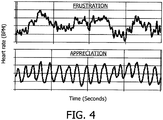
- Fig. 4 shows how heart rate and respiration synchronize if a patient is in a positive or relaxed mood ("high coherence"), compared to the de-synchronization found if the patient is in a negative or stressed mood (low coherence).
- high coherence the positive or relaxed mood
- negative or stressed mood low coherence
- the variation of the heart rate occurs in a sine wave manner.
- the third preferred embodiment of the invention allows to conduct simultaneously a measurement of heart rate variation and breathing activity, so the degree of coherence between the two can be calculated and used as a measure indicating the relaxation level of the patient. This can be done as follows:
- the calculated degree of coherence is high, because positive values from the respiration segment are multiplied with positive values from the heart rate segment, and negative values from the respiration segment are multiplied with negative values from the heart rate segment. So in this case, all elements contributing to the sum calculation are positive.
- maxima in the one segment coincide with minima in the other segment, the sum result is smaller in this case, because then positive values from the one segment are multiplied with negative values from the other segment, giving negative contributions to the sum calculation.
- a guidance signal indicating how the patient should breathe, is added to the system.
- the guidance signal can be adapted according to the relaxation status of the patient.
- a block-diagram is depicted which shows a system according to a preferred embodiment: Additionally to the device shown in Fig. 3 , according to this preferred embodiment of the invention a coherence calculator 26 is provided which is fed by the outputs of heart rate calculator 17 and breathing calculator 25. The ouput of coherence calculator 26 is then fed to a relaxation assessment unit 27 which also receives the output signal from PAT calculator 21. Finally an output device 28 like a display, a loudspeaker, an illumination or the like is provided for giving breathing instructions to the patient and/or for indicating the stress status.
- the area 29 in Fig. 6 which is enclosed by a dashed line shows digital signal processing blocks that are preferably implemented on a microprocessor. As can be seen in Fig. 6 , not only the degree of coherence between heart rate variation and breathing is taken into account in order to assess the relaxation level of the patient, but it is proposed to also use the blood pressure value determined with the help of the pulse arrival time of the pulse wave in the finger for this purpose.
Landscapes
- Health & Medical Sciences (AREA)
- Life Sciences & Earth Sciences (AREA)
- Physics & Mathematics (AREA)
- Surgery (AREA)
- General Health & Medical Sciences (AREA)
- Biophysics (AREA)
- Pathology (AREA)
- Engineering & Computer Science (AREA)
- Biomedical Technology (AREA)
- Heart & Thoracic Surgery (AREA)
- Medical Informatics (AREA)
- Molecular Biology (AREA)
- Veterinary Medicine (AREA)
- Animal Behavior & Ethology (AREA)
- Public Health (AREA)
- Cardiology (AREA)
- Physiology (AREA)
- Pulmonology (AREA)
- Vascular Medicine (AREA)
- Spectroscopy & Molecular Physics (AREA)
- Optics & Photonics (AREA)
- Dentistry (AREA)
- Oral & Maxillofacial Surgery (AREA)
- Measuring Pulse, Heart Rate, Blood Pressure Or Blood Flow (AREA)
- Measurement Of The Respiration, Hearing Ability, Form, And Blood Characteristics Of Living Organisms (AREA)
- Measurement And Recording Of Electrical Phenomena And Electrical Characteristics Of The Living Body (AREA)
- Measuring And Recording Apparatus For Diagnosis (AREA)
Abstract
Description
- The invention relates to the field of contactless respiration monitoring of a patient and an optical sensor for a photoplethysmography measurement, and especially to a handheld device for simultaneously monitoring respiration action, blood pressure and heart rate which can preferably used for spot-checking the vital parameters of patients in hospitals.
- It is possible to detect the pulse wave arrival in a finger of a patient by means of an optical measurement: Typically, an infrared LED shines light into the finger and the amount of light that reaches a photodiode causes a photo current to flow through the diode. In the presence of the pulse wave, a large portion of the light is absorbed by the blood, i.e. the current through the photodiode is modulated accordingly. This technique is known as photoplethysmography (PPG).
- It is called "transmittive" PPG, if LED and photodiode are installed on opposite sides of the finger, such that the LED light actually shines through the finger. Such a setup is usually realised as a finger-clip. The other option is to have both LED and photodiode installed on the same side of the finger. This is called "reflective" PPG, and is useful if a finger-clip is not acceptable. In reflective mode, LED and photodiode sit next to each other, so that the patient only has to rest his finger on the two components in order to have his pulse wave detected, e.g. for heart rate measurements or pulse arrival time (PAT) measurements.
- A reflective PPG setup is useful in many cases. It requires the patient only to put his finger lightly onto the LED/photodiode combination in order to have his pulse wave detected. This can be used for heart rate measurements, for example. Another application of PPG is the measurement of a pulse transit time (PTT) or of a pulse arrival time (PAT). The principle of a PTT measurement is that one takes the moment in time, when the pulse wave starts at one point of the body, and measures the arrival time at another point of the body. The PTT is calculated as the time difference between the two and is inversely related to the pulse wave velocity. The PAT is defined as the time delay between the ECG R-peak and the arrival of the PPG pulse at some peripheral site. The PPG measurements are usually done on the patient's ear lobe or on a finger.
- Both PTT and PAT are interesting measures, because among other parameters, like the distance between the two measurement locations on the body and the elasticity of the blood vessels, they provide information on the blood pressure of the patient. So if the other parameters are known or can be estimated, blood pressure can be inferred from a PTT or PAT measurement.
- Actually, the R peak in the ECG signal does not coincide with the start of the pressure pulse propagation in the aorta. This is because the ECG R peak is the electrical excitation of the heart muscle. It takes some time before the muscle reacts to this excitation, and then it takes even more time before the muscle has built up sufficient pressure in the heart, so that the aortic valve opens and the pulse wave really starts to travel through the arteries. However, the time delay between the R-peak and the aortic valve opening also conveys important information on the arterial blood pressure. Hence, taking the R peak as the start point for deducing the pulse wave arrival time at periphery is acceptable in many applications.
- Many attempts have been made in the past to use this principle in order to provide a blood pressure measurement that does not need a cuff. Typical PAT measurement setups comprise an ECG measurement and a PPG measurement. A characteristic point of the PPG pulse is taken as the moment in time when the pulse wave arrives in the finger or ear. The difference between the occurrence time of the ECG R-peak and of the PPG characteristic point is calculated, which is translated into a blood pressure value.
- The problem especially encountered in reflective PPG setups is that the pressure, with which the skin is pressed onto the LED/photodiode combination, can be so high, that the blood vessels are actually clamped off, so that the pulse wave does not reach the measurement location and therefore cannot be detected.
- Further, spot-checking the vital parameters of patients in hospital beds is part of a nurse's daily routine. Heart rate, breathing frequency, blood pressure and body temperature are the most important parameters that should be checked for every patient. Measuring all these parameters properly would require a substantial effort, both in terms of measurement equipment and time. However, the practical circumstances in a hospital force the nurses to be as quick as possible with the spot-check measurements, because they have many other tasks to do, requiring more attention than the routine spot-checking.
- Especially, respiratory action cannot be measured with conventional spot-checking setups yet. For that, a breathing sensor would be required. In general, such a breathing sensor had to be attached to the chest of the patient. However, attaching a sensor to the patient's chest is inconvenient and time-consuming.
-
US 2008/0077015A1 discloses a Doppler radar system, which may be a hand-held device, for determining physiological motion with a subject, for example heart rate and/or respiration rate of the subject. The heart rate may be compared with a reference obtained from a wired finger pressure pulse sensor. -
WO 2008/027509A2 discloses a remote-detection system for monitoring changes in permittivity associated with physiological activity of a subject. Tissue of the subject is illuminated with an electromagnetic signal beam, and the reflections of the electromagnetic signal beam from the subject are detected by the system. The reflected signal includes amplitude variations indicative of motion of the illuminated tissue and amplitude variations indicative of time dependent variations in the permittivity of the illuminated tissue associated with electrical activity of the subject's heart. From the reflected signal a respiration signal structure is detected and measured next to a determination of the heart rate activity. -
US 2005/0288601A1 discloses a portable handheld biofeedback device for evaluating and treating stress by identifying respiratory sinus arrhythmia (RSA) waves during respiration. The device contains a photoplethysmograph sensor and a display screen to provide subjects with near real-time information on their RSA waves. These wave patterns are used to provide a subject with near real-time respiratory feedback information based on heart rate data. Means for decreasing or adequately controlling stress levels are provided based on the wave pattern analysis and respiratory feedback. - It is an object of the invention to provide for a convenient and easy to use spot-checking possibility of the patient's respiratory action.
- This object is met by a handheld device according to
claim 1. - A solution for measuring respiratory action of a patient without body contact is described. It is in particular suitable for the integration into a handheld device. With respect to this the handheld device comprises a holding means which is adapted for holding the device in front of the patient's chest by the patient himself. Furthermore, it is preferred that the calculated breathing activity preferably comprises the respiration rate of the patient.
- The invention provides for several advantages: Contactless measurement of respiratory action is integrated in a handheld device. Further, an easy-to-use handheld solution for doing spot-checking of heart rate, blood pressure and breathing frequency can be provided as set out in more detail in the following. Furthermore, an easy-to-use handheld solution for doing relaxation exercises, for example including breathing guidance, can be provided as set out in detail further below.
- In general, different types of distance sensors like ultrasound sensors and/or laser sensors can be used. With the help of ultrasound, distance can be measured. A short ultrasound burst is transmitted towards the target, reflected at the target, and the time until the reflected burst arrives is measured. The flight time is directly proportional to the distance, because the propagation velocity is constant during the short time of measurement. Further, with the help of laser interferometry, it is possible to measure relative motion very precisely. The phase difference between emitted laser beam and reflected laser beam depends on the distance to the reflecting target, so if the reflected beam is brought to interfere with a beam that is in phase with the emitted beam, the intensity of the interference result varies periodically.
- However, according to a preferred embodiment of the invention, the distance sensor is based on emitting and receiving electromagnetic waves. Further, it is preferred that the distance sensor comprises a Doppler radar sensor, preferably a two-channel Doppler radar sensor. Radar frequencies of 2.4GHz or 24GHz have shown to deliver good results.
- The use of electromagnetic waves has the advantage, that they are not reflected at the clothing, but at the skin surface. Basically, reflection of electromagnetic waves occurs at boundary layers between areas of different electrical conductivity. Since the air is an electric isolator, and the clothing is usually also an isolator, there will be a reflection indeed at the surface of the skin. This is a great advantage of using electromagnetic waves.
- If the reflecting target, which in this case would be the chest of the patient, is moving due to the respiratory action, the reflected electromagnetic waves are shifted in frequency with respect to the emitted waves (Doppler shift). This frequency difference can be detected and exploited as a measure for the chest motion of the patient. The principle of this measurement is known from traffic speed controls, for example. The antenna of a radar transceiver can be easily integrated in a handheld device in a way that the electromagnetic waves are directed towards the chest of the patient holding the device in his hands.
- The holding means is adapted for automatically directing the distance sensor towards the patient's chest when held with both hands of the patient. In this way the handheld device is automatically aligned and no additional adjustment is necessary.
- Further, the holding means comprises two handles for grabbing the device with both hands of the patient. The handles comprise electrodes for an ECG measurement. With respect to this, the handles are preferably made of metal. Furthermore, it is preferred that an ECG measuring unit is provided in the device.
- According to the invention, an optical sensor for a photoplethysmography measurement, preferably an optical sensor as described below, is provided on the device. With respect to this, it is especially preferred that a reflective mode sensor is provided. Further, according to the invention, the optical sensor is positioned on the device in such a way that, when holding the device, a patient's finger, preferably a patient's thumb, automatically rests on the sensor. This makes the device more reliable also with respect to the photoplethysmography measurement. Furthermore, it is also preferred that a photoplethysmography measuring unit is provided in the device which is adapted for determining the blood pressure of the patient.
- An embodiment of the invention provides a possibility for a reliable and fail-safe photoplethysmography measurement. In this embodiment the optical sensor for the photoplethysmography measurement, comprises a light unit with a light emitter for emitting light into tissue of a patient and/or a light detector for detecting a part of the emitted light after interaction with the tissue, wherein the light unit is embedded in an elastic material.
- Accordingly, it is an essential idea of this embodiment to provide an elastic material which, when pressed by a patient's fingertip, is resilient and, thus, avoids clamping of capillaries in the patient's tissue. This comprises several advantages as intuitive usage of reflective finger PPG setups, and no explanation to the patient how the finger has to be applied. Further, this allows valid measurements in a reflective PPG setup irrespective of the pressure exerted on the skin that is pressed onto the light unit. Thus, this solution is simple, passive and inexpensive.
- According to a preferred embodiment of the invention, the elastic material is adapted for being contacted by the patient's skin, preferably by a patient's fingertip. Further, it is preferred that the elasticity of the elastic material lies in the range of typical elasticities of the tissue of a human finger. Preferably, silicone is used for the elastic material.
- In general, the invention can be applied for different types of photoplethysmography measurements. However, according to a preferred embodiment of the invention, the light unit is adapted for a reflective photoplethysmography measurement. With respect to this, according to a preferred embodiment of the invention, the light unit comprises an LED and a photodiode. Moreover, it is preferred that the elastic material is not transparent for the light emitted by the light emitter. This is advantageous since in this way, a direct light path from the light emitter to the light detector is avoided. Preferably, the feature that the elastic material is not transparent for the light emitted by the light emitter is achieved by color additives to the elastic materials.
- The device described above can be used for different applications, preferably for spot-checking applications in hospitals. However, according to a preferred embodiment of the invention, an output unit is provided in the device, the output unit being adapted for outputting a stress status indicator signal, based on coherence between determined heart rate and determined breathing activity. This idea will be more apparent with the method described in the following.
- A method of providing a patient with a stress status indicator signal is provided, preferably with the aid of a device as described above, comprising the following steps:
- detecting the patient's heart rate;
- simultaneously detecting the patient's breathing activity;
- calculating the degree of coherence between the heart rate and the breathing activity; and
- outputting a stress status indicator signal based on the calculated degree of coherence.
- Under resting conditions, the heart rate of healthy patients exhibits a periodic variation. This rhythmic phenomenon, known as respiratory sinus arrhythmia (RSA), fluctuates with the phase of respiration: the heart rate increases during inspiration and decreases during expiration. In this way the heart rate tends to synchronize with the patient's breathing activity under certain conditions. Heart rate and respiration synchronize if a patient is in a positive or relaxed mood ("high coherence"), compared to the de-synchronization found if the patient is in a negative or stressed mood (low coherence). In the positive mood, the variation of the heart rate typically occurs in a sine wave manner. This allows to conduct simultaneously a measurement of heart rate variation and breathing activity, so the degree of coherence between the two can be calculated and used as a measure indicating the relaxation level of the patient.
- According to a preferred embodiment of the invention, a guidance signal is output, indicating how the patient should breathe. Further, it is preferred that the guidance signal is automatically adapted according to the determined stress status of the patient.
- Preferred applications of the invention are as follows: The invention allows contactless measurement of respiration in a handheld device. It is of particular value in a handheld device for spot-checking a patient's heart rate, blood pressure and respiratory frequency simultaneously. Furthermore, it can be used in order to build a very attractive handheld solution for giving guided breathing exercises as a technique to relax effectively from stressful situations.
- These and other aspects of the invention will be apparent from and elucidated with reference to the embodiments described hereinafter.
- In the drawings:
-
Fig. 1 a and b schematically show a reflective PPG setup as in preferred embodiment of the invention; -
Fig. 2a, b and c shows a handheld device according to the invention held by a patient; -
Fig. 3 depicts a block diagram of the system according to the invention; -
Fig. 4 shows how heart rate and respiration synchronize if a patient is in a positive or relaxed mood, compared to the de-synchronization found if the patient is in a negative or stressed mood; -
Fig. 5 explains the calculation of coherence according to a preferred embodiment of the invention; and -
Fig. 6 shows a block diagram of a system according to a preferred embodiment of the invention. - According to a preferred embodiment of the invention, it is proposed to embed the
light unit 1 of an optical sensor for a reflective photoplethysmography measurement with itslight emitter 2 and itslight detector 3, i.e. with its LED/photodiode combination, into anelastic material 4, e.g. silicone, that will give way to the finger pressure. An according reflective PPG setup can be seen fromFig. 1 . There, it is shown that a patient'sfinger 5 is pressed on theelastic material 4 in which thelight unit 1 with thelight emitter 2 and thelight detector 3 are provided. On its border area, theelastic material 4 is surrounded by arigid carrier 6. In this way clamping of thefinger capillaries 7 is avoided over a wide range of finger pressures. - As can be seen from
Fig. 1 , theelastic material 4 is deformed depending on the amount of finger pressure applied, and because of this deformation, clamping of thecapillaries 7 is avoided, thereby allowing a valid PPG measurement in this reflective PPG setup over a wide range of finger pressures. In order to achieve a wide range of tolerated finger pressures, it is preferred to choose the elasticity of theelastic material 4, in which the LED/photodiode combination is embedded, such that it is equal or similar to the elasticity of finger tissue. Theelastic material 4 preferably is not transparent for the light emitted by the LED, in order to avoid a direct light path from the LED to the photodiode. This is preferably achieved with the help of color additives to the silicone, if required. - From
Figs 2 a, b, and c , ahandheld device 9 according to the invention can be seen. The general idea of thishandheld device 9 is based on the insight that if apatient 8 holds the handheld device with both hishands 10, there is a free line ofsight 11 between thehandheld device 9 and the patient'schest 12 as shown inFig. 2a , and more in detail inFigs 2b and 2c . Furthermore, the anatomy of the human arm and wrist is such that if the device has twohandles 13 at the side which the patient grabs with hishands 10, thelid 14 of thehandheld device 9 is automatically adjusted to point at the patient'schest 12.Figs. 2b and 2c illustrate this condition. - Since the wall of the patient's
chest 12 moves forward and backward due to the respiratory action, a distance sensor is integrated into thelid 14 of thehandheld device 9 that measures the distance between thelid 14 and thechest 12. Different sensor modalities are conceivable for this purpose, as described further above. - According to the preferred embodiment of the invention described here, as a distance sensor a transceiver of electromagnetic waves is provided in the
handheld device 9. Experiments indicate that radar frequencies give acceptable results, preferably frequencies of 2.4GHz or 24GHz. The antenna of the radar transceiver can be easily integrated in thehandheld device 9 in a way that the electromagnetic waves are directed towards thechest 12 of thepatient 8 holding thehandheld device 9 in hishands 10. - A block diagram of the system according to the invention is shown in
Fig. 3 . Thehandheld device 9 provides for three different measurements: heart rate, blood pressure and breathing activity. For that, the handheld device according to the invention is designed as follows: - For the heart rate measurement, the
handheld device 9 comprises two electrodes which are formed bymetal handles 13 which also serve for holding the handheld device. Thehandles 13 are connected to an ECG measuring unit comprising anECG amplifier 15 and apeak detector 16. Then, the heart rate is calculated in aheart rate calculator 17. - For the blood pressure measurement, the
handheld device 9 further comprises anoptical sensor 18 for a photoplethysmography measurement which may be designed as described above. Thisoptical sensor 18 is connected to a photoplethysmography measuring unit which comprises aphoto amplifier 19 and apulse detector 20. Then, the signal determined by thepulse detector 20 is output to a PAT (pulse arrival time)calculator 21 which also receives the signal output by thepeak detector 16 of the ECG measuring unit. In thePAT calculator 21, the blood pressure is deduced from the PAT value and the ECG signal. - For the measurement of the breathing activities, the
handheld device 9 is provided with a Doppler radar unit comprising anantenna 22 which emits electromagnetic waves towards the patient'schest 12 and receives electromagnetic waves reflected from the patient'schest 12. The signal received by theantenna 22 is fed to an RFfront end 23 which is connected to amotion sensor 24. The signal output by themotion sensor 24 is then fed to abreathing rate calculator 25 for calculating the breathing rate of thepatient 8. - In this way, an easy-to-use handheld solution for doing spot-checking of heart rate, blood pressure and breathing frequency is created. The solution is highly useful in hospital applications, in particular the so-called "spot-checking", when a nurse walks from patient bed to patient bed and wants to determine as quickly as possible vital parameters like heart rate, blood pressure and breathing rate.
- At the moment, the nurse determines the patient's breathing rate by putting her hand onto the chest of the patient and looking at her wrist watch in order to see how many seconds a breathing cycle lasts. This method is rather inaccurate and bothersome for the nurse, so sometimes she just writes down an assumed figure. With the help of this preferred embodiment of the invention, these problems are overcome. The nurse simply gives the handheld device to the patient. He holds the device for a few seconds, during which his ECG, his pulse arrival time in the finger and his chest movement are measured with the help of the electrodes in the
handles 13, theoptical sensor 18 for the thumb and the Doppler radar, respectively. - From the ECG, it is easy to extract the heart rate. The pulse arrival time obtained with the help of the optical sensor is translated into blood pressure readings, and the Doppler radar measurement allows for determining the respiration rate. This way, all relevant parameters are captured with the help of a single, easy-to-use handheld device. The data can be stored directly on the
handheld device 9 or transmitted through a wireless link, which is not shown inFig. 3 . - According to a preferred embodiment of the invention, the measurement of heart rate, blood pressure and respiration are used to give feedback to the
patient 8 about his stress status. If combined with breathing instructions, ahandheld device 9 for doing guided relaxation exercises is created. - Under resting conditions, the heart rate of healthy individuals exhibits a periodic variation. This rhythmic phenomenon, known as respiratory sinus arrhythmia (RSA), fluctuates with the phase of respiration: the heart rate increases during inspiration and decreases during expiration. This way the heart rate tends to synchronize with the patient's breathing activity under certain conditions.
-
Fig. 4 shows how heart rate and respiration synchronize if a patient is in a positive or relaxed mood ("high coherence"), compared to the de-synchronization found if the patient is in a negative or stressed mood (low coherence). In the positive mood, the variation of the heart rate occurs in a sine wave manner. The third preferred embodiment of the invention allows to conduct simultaneously a measurement of heart rate variation and breathing activity, so the degree of coherence between the two can be calculated and used as a measure indicating the relaxation level of the patient. This can be done as follows: - As shown in
Fig. 5 , instep 1, segments from the respiration rate signal and from the heart rate signal are cut from the original signals, both comprising N samples, respectively. Then, instep 2, the DC components from both segments are removed, and the amplitudes are normalized. Finally, instep 3, the coherence is calculated as the cross-correlation between the two segments:
- If the maxima in the respiratory signal coincide with the maxima in the heart rate signal, as it is shown in
Fig. 5 , the calculated degree of coherence is high, because positive values from the respiration segment are multiplied with positive values from the heart rate segment, and negative values from the respiration segment are multiplied with negative values from the heart rate segment. So in this case, all elements contributing to the sum calculation are positive. One can easily imagine that if maxima in the one segment coincide with minima in the other segment, the sum result is smaller in this case, because then positive values from the one segment are multiplied with negative values from the other segment, giving negative contributions to the sum calculation. Preferably, a guidance signal, indicating how the patient should breathe, is added to the system. The guidance signal can be adapted according to the relaxation status of the patient. - In
Fig. 6 a block-diagram is depicted which shows a system according to a preferred embodiment: Additionally to the device shown inFig. 3 , according to this preferred embodiment of the invention acoherence calculator 26 is provided which is fed by the outputs ofheart rate calculator 17 andbreathing calculator 25. The ouput ofcoherence calculator 26 is then fed to arelaxation assessment unit 27 which also receives the output signal fromPAT calculator 21. Finally anoutput device 28 like a display, a loudspeaker, an illumination or the like is provided for giving breathing instructions to the patient and/or for indicating the stress status. - The
area 29 inFig. 6 which is enclosed by a dashed line shows digital signal processing blocks that are preferably implemented on a microprocessor. As can be seen inFig. 6 , not only the degree of coherence between heart rate variation and breathing is taken into account in order to assess the relaxation level of the patient, but it is proposed to also use the blood pressure value determined with the help of the pulse arrival time of the pulse wave in the finger for this purpose. - While the invention has been illustrated and described in detail in the drawings and foregoing description, such illustration and description are to be considered illustrative or exemplary and not restrictive; the invention is not limited to the disclosed embodiments.
- Other variations to the disclosed embodiments can be understood and effected by those skilled in the art in practicing the claimed invention, from a study of the drawings, the disclosure, and the appended claims. In the claims, the word "comprising" does not exclude other elements or steps, and the indefinite article "a" or "an" does not exclude a plurality. The mere fact that certain measures are recited in mutually different dependent claims does not indicate that a combination of these measured cannot be used to advantage. Any reference signs in the claims should not be construed as limiting the scope. Further, a patient is understood to be a human being or an animal which not necessarily has to be ill or diseased.
Claims (14)
- A handheld device (9) for contactless respiration monitoring of a patient (8), comprising:a distance sensor for consecutively detecting the temporal distance variations relative to the patient's chest (12);a calculating unit (25) for determining the breathing activity based on the detected temporal distance variations; characterised bytwo handles (13) adapted for holding the device with both hands (10) of the patient (8) such that the distance sensor is directed to the patient's chest (12), and wherein the handles (13) comprise electrodes for an ECG measurement; andan optical sensor (18) for a photoplethysmography measurement provided on the device (9) such that, when holding the device (9), a finger (5) of the patient (8) automatically rests on the optical sensor (18).
- The device according to claim 1, wherein the distance sensor is based on emitting and receiving electromagnetic waves, and preferably comprises a Doppler radar sensor, preferably a two-channel Doppler radar sensor.
- The device according to any of claims 1 to 2, wherein the handks (13) are connected to an ECG measuring unit (15,16) provided in the device.
- The device according to any of claims 1 to 3, wherein the handheld device further comprises a heart rate calculator (17) for calculating the heart rate of the patient (8) from the ECG measurement.
- The device according to any of claims 1 to 4, wherein a photoplethysmography measuring unit (19, 20) which is connected to the optical sensor (18) is provided in the device and wherein the device is adapted for determining the blood pressure of the patient (8).
- The device according to claim 5 further comprising a pulse arrival time calculator (21) for calculating a pulse arrival time, wherein the pulse arrival time calculator (21) is adapted for receiving the signal determined by a pulse detector (20) of the photoplethysmography measuring unit (19, 20) and adapted for receiving the signal output by a peak detector (16) of the ECG measuring unit (15, 16) and adapted for deducing the blood pressure of the patient (8) from the calculated pulse arrival time value and the ECG measurement.
- The device according to claim 4, wherein the device further comprises an output unit (28) which is adapted for outputting a stress status indicator signal, based on coherence between the determined heart rate and the determined breathing activity.
- The device according to claim 5, wherein the device further comprises an output unit (28) which is adapted for outputting a stress status indicator signal, based on coherence between the determined heart rate and the determined breathing activity and also based on the blood pressure value of the patient (8).
- The device according to claim 7 or 8, wherein the output unit (28) further provides a guidance signal indicating how the patient (8) should breathe, wherein the guidance signal is automatically adapted according to the determined stress status of the patient (8).
- The device according to any of claims 1 to 9, wherein the optical sensor (18) comprises a light unit (1) with a light emitter (2) for emitting light into tissue of a patient (8) and/or a light detector (3) for detecting a part of the emitted light after interaction with the tissue, wherein the light unit (1) is embedded in an elastic material (4).
- The device according to claim 10, wherein the elastic material (4) is adapted for being contacted by the patient's finger (5).
- The device according to claim 10 or 11, wherein the elasticity of the elastic material (4) lies in the range of typical elasticities of the tissue of a human finger.
- The device according to any of claims 10 to 12, wherein the light unit (1) comprises an LED and a photodiode.
- The device according to any of claims 10 to 13 wherein the elastic material (4) is not transparent for the light emitted by the light emitter (2).
Priority Applications (1)
| Application Number | Priority Date | Filing Date | Title |
|---|---|---|---|
| EP09742514A EP2291111B1 (en) | 2008-05-09 | 2009-05-04 | Contactless respiration monitoring of a patient and optical sensor for a photoplethysmography measurement |
Applications Claiming Priority (3)
| Application Number | Priority Date | Filing Date | Title |
|---|---|---|---|
| EP08103895 | 2008-05-09 | ||
| EP09742514A EP2291111B1 (en) | 2008-05-09 | 2009-05-04 | Contactless respiration monitoring of a patient and optical sensor for a photoplethysmography measurement |
| PCT/IB2009/051806 WO2009136341A2 (en) | 2008-05-09 | 2009-05-04 | Contactless respiration monitoring of a patient and optical sensor for a photoplethysmography measurement |
Publications (2)
| Publication Number | Publication Date |
|---|---|
| EP2291111A2 EP2291111A2 (en) | 2011-03-09 |
| EP2291111B1 true EP2291111B1 (en) | 2012-04-25 |
Family
ID=40957793
Family Applications (1)
| Application Number | Title | Priority Date | Filing Date |
|---|---|---|---|
| EP09742514A Not-in-force EP2291111B1 (en) | 2008-05-09 | 2009-05-04 | Contactless respiration monitoring of a patient and optical sensor for a photoplethysmography measurement |
Country Status (8)
| Country | Link |
|---|---|
| US (1) | US20110054277A1 (en) |
| EP (1) | EP2291111B1 (en) |
| JP (2) | JP2011519657A (en) |
| CN (1) | CN102014737B (en) |
| AT (1) | ATE554704T1 (en) |
| ES (1) | ES2386111T3 (en) |
| RU (1) | RU2511278C2 (en) |
| WO (1) | WO2009136341A2 (en) |
Families Citing this family (52)
| Publication number | Priority date | Publication date | Assignee | Title |
|---|---|---|---|---|
| ES2366089B1 (en) * | 2010-03-30 | 2012-09-27 | Creaciones Madu, S.A. | DEVICES FOR MEASURING AND CONTROLLING VITAL CONSTANTS IN BABIES AND DURING THE FIRST YEARS OF CHILDHOOD. |
| US20150150514A1 (en) | 2010-08-06 | 2015-06-04 | Conceptual Mindworks, Inc. | Patient Care Recommendation System |
| US8679024B2 (en) * | 2010-10-26 | 2014-03-25 | Medtronic, Inc. | System and method for deriving respiration from intracardiac electrograms (EGM) or ECG signals |
| US8761853B2 (en) * | 2011-01-20 | 2014-06-24 | Nitto Denko Corporation | Devices and methods for non-invasive optical physiological measurements |
| US9289177B2 (en) | 2011-01-20 | 2016-03-22 | Nitto Denko Corporation | Sensing device, a method of preparing a sensing device and a personal mobile sensing system |
| EP3312629A3 (en) | 2011-02-21 | 2018-06-13 | Transrobotics, Inc. | System and method for sensing an object's dimensions |
| US8740793B2 (en) | 2011-08-29 | 2014-06-03 | General Electric Company | Radar based systems and methods for monitoring a subject |
| CN102509419B (en) * | 2011-10-31 | 2013-06-05 | 中国人民解放军第四军医大学 | Wireless driver fatigue monitoring device |
| CN103190892A (en) * | 2012-01-04 | 2013-07-10 | 深圳比科斯电子股份有限公司 | Multipurpose human body health care measurement system |
| WO2013111141A1 (en) | 2012-01-29 | 2013-08-01 | Sensible Medical Innovations Ltd. | Deriving individual thoracic parameters of a subject |
| US10405791B2 (en) * | 2013-03-15 | 2019-09-10 | Yingchang Yang | Method and continuously wearable noninvasive apparatus for automatically detecting a stroke and other abnormal health conditions |
| US9339193B2 (en) | 2012-05-21 | 2016-05-17 | Fujitsu Limited | Physiological adaptability system with multiple sensors |
| KR102025571B1 (en) * | 2012-07-27 | 2019-09-27 | 삼성전자주식회사 | Apparatus and method for measuring change in blood pressure caused by breathing control |
| EP3828591A1 (en) * | 2012-10-05 | 2021-06-02 | Transrobotics, Inc. | Systems and methods for high resolution distance sensing and applications |
| BR112015007636A2 (en) | 2012-10-09 | 2017-07-04 | Koninklijke Philips Nv | patient breathing monitoring device, and a patient's breathing rate monitoring method |
| US10265022B2 (en) | 2012-10-30 | 2019-04-23 | Nokia Technologies Oy | Determining biometrics utilizing a display-embedded distance-measuring sensor |
| CN105307568B (en) * | 2013-02-13 | 2018-11-16 | 莱曼微设备有限公司 | non-invasive blood analysis |
| EP2769667A1 (en) * | 2013-02-22 | 2014-08-27 | Koninklijke Philips N.V. | Marker with light emitting area for use in determining vital sign information |
| CN103637787B (en) * | 2013-12-02 | 2016-02-10 | 清华大学 | The method of blood pressure real-time measurement apparatus and in real time measurement pulse wave transmission time difference |
| US20150250398A1 (en) * | 2014-03-06 | 2015-09-10 | Medsense Inc. | Sensor module for simultaneously measuring ecg and pulse signal |
| DE102014104465B3 (en) * | 2014-03-28 | 2015-06-11 | LifeTAix GmbH | Measuring method for recording vital parameters on the body of a human or an animal and a measuring arrangement |
| RU2653834C2 (en) * | 2014-06-30 | 2018-05-14 | Конинклейке Филипс Н.В. | Photoplethysmography sensor apparatus and method |
| EP4027215A1 (en) * | 2014-09-04 | 2022-07-13 | Leomo, Inc. | Information terminal device, motion capture system and motion capture method |
| TWI547265B (en) * | 2015-06-01 | 2016-09-01 | 原相科技股份有限公司 | Optical respiration rate detection device and detection method thereof |
| RU2601697C2 (en) * | 2014-10-31 | 2016-11-10 | Общество с ограниченной ответственностью "ХЕЛФИ-СТИЛЬ" | Device and method for measuring human arterial pressure value |
| KR102390369B1 (en) * | 2015-01-21 | 2022-04-25 | 삼성전자주식회사 | Apparatus for detecting information of the living body |
| CN104840218B (en) * | 2015-06-09 | 2018-08-10 | 联想(北京)有限公司 | A kind of measurement method and electronic equipment of respiratory rate |
| CN105147293A (en) * | 2015-08-21 | 2015-12-16 | 姚丽峰 | System and method for measuring respiratory rate |
| US10398328B2 (en) | 2015-08-25 | 2019-09-03 | Koninklijke Philips N.V. | Device and system for monitoring of pulse-related information of a subject |
| RU169652U1 (en) * | 2015-09-14 | 2017-03-28 | Общество с ограниченной ответственностью "Найтек" | PORTABLE DEVICE FOR REGISTRATION OF ELECTROCARDIOGRAMS |
| US9801587B2 (en) * | 2015-10-19 | 2017-10-31 | Garmin Switzerland Gmbh | Heart rate monitor with time varying linear filtering |
| EP3361939A4 (en) * | 2015-11-16 | 2019-06-12 | Respirix, Inc. | Devices and methods for monitoring physiologic parameters |
| US10987008B2 (en) | 2015-12-21 | 2021-04-27 | Koninklijke Philips N.V. | Device, method and computer program product for continuous monitoring of vital signs |
| EP3351168B1 (en) | 2017-01-20 | 2019-12-04 | Nokia Technologies Oy | Arterial pulse measurement |
| US10993627B1 (en) * | 2017-01-24 | 2021-05-04 | James Eric Dotter | Device for determining blood pressure without a cuff |
| US10555679B2 (en) * | 2017-06-20 | 2020-02-11 | General Electric Company | Non-contact heart rate monitoring |
| EP3488781B1 (en) | 2017-11-28 | 2022-05-18 | Current Health Limited | Apparatus and method for estimating respiration rate |
| US20190343442A1 (en) * | 2018-05-10 | 2019-11-14 | Hill-Rom Services Pte. Ltd. | System and method to determine heart rate variability coherence index |
| EP3636144B1 (en) | 2018-10-11 | 2023-06-07 | Current Health Limited | Monitoring apparatus and method |
| CN109330571A (en) * | 2018-11-08 | 2019-02-15 | 杭州兆观传感科技有限公司 | A kind of elasticity photoelectric sensor mould group |
| CN109691999A (en) * | 2019-01-21 | 2019-04-30 | 深圳瀚维智能医疗科技有限公司 | Respiratory rate detection method, device, storage medium and computer equipment |
| US11703593B2 (en) | 2019-04-04 | 2023-07-18 | TransRobotics, Inc. | Technologies for acting based on object tracking |
| JP2022532844A (en) * | 2019-05-08 | 2022-07-20 | バクスター・インターナショナル・インコーポレイテッド | Patch type physiological sensor |
| EP3534373A3 (en) * | 2019-06-04 | 2019-09-11 | Polar Electro Oy | System for measuring stress level |
| JP7235120B2 (en) * | 2019-08-08 | 2023-03-08 | 日本電信電話株式会社 | Sphygmomanometer |
| EP3811862A1 (en) | 2019-10-22 | 2021-04-28 | Oxypoint NV | Vital parameter measurements for low care patients |
| US20220361753A1 (en) | 2019-10-22 | 2022-11-17 | Oxypoint Nv | Vital parameter measurements for low care patients |
| WO2021237742A1 (en) * | 2020-05-29 | 2021-12-02 | 深圳迈瑞生物医疗电子股份有限公司 | Monitoring device having non-contact physiological sign monitoring function |
| CN114469020A (en) * | 2020-10-26 | 2022-05-13 | 南京华曼吉特信息技术研究院有限公司 | Physiological parameter detector |
| CN112914583B (en) * | 2021-02-25 | 2022-10-21 | 中国人民解放军陆军特色医学中心 | Method for determining arrangement position of electrocardiogram acquisition electrodes in non-contact manner |
| WO2023068372A1 (en) * | 2021-10-22 | 2023-04-27 | アステラス製薬株式会社 | Thoracic motion measurement device, thoracic motion measurement program, and non-temporary storage medium |
| WO2024158155A1 (en) * | 2023-01-25 | 2024-08-02 | 자이메드 주식회사 | Biometric signal measurement device and biomietric signal measurement system comprising same |
Family Cites Families (33)
| Publication number | Priority date | Publication date | Assignee | Title |
|---|---|---|---|---|
| US7467809B2 (en) * | 1992-05-05 | 2008-12-23 | Automotive Technologies International, Inc. | Vehicular occupant characteristic determination system and method |
| DE3809084C2 (en) * | 1988-03-18 | 1999-01-28 | Nicolay Gmbh | Sensor for the non-invasive measurement of the pulse frequency and / or the oxygen saturation of the blood and method for its production |
| US4825872A (en) * | 1988-08-05 | 1989-05-02 | Critikon, Inc. | Finger sensor for pulse oximetry system |
| JP2505073B2 (en) * | 1991-05-28 | 1996-06-05 | 松下電工株式会社 | Refresh device |
| JPH0622914A (en) * | 1992-05-12 | 1994-02-01 | Mitsubishi Motors Corp | Heart rate detecting device |
| US5839439A (en) * | 1995-11-13 | 1998-11-24 | Nellcor Puritan Bennett Incorporated | Oximeter sensor with rigid inner housing and pliable overmold |
| US5913819A (en) * | 1996-04-26 | 1999-06-22 | Datex-Ohmeda, Inc. | Injection molded, heat-sealed housing and half-etched lead frame for oximeter sensor |
| US5865755A (en) * | 1996-10-11 | 1999-02-02 | Dxtek, Inc. | Method and apparatus for non-invasive, cuffless, continuous blood pressure determination |
| WO1998017174A1 (en) * | 1996-10-23 | 1998-04-30 | Cardiac Crc Nominees Pty. Limited | Non-invasive determination of oxygen saturation in blood in deep tissue |
| US6525386B1 (en) * | 1998-03-10 | 2003-02-25 | Masimo Corporation | Non-protruding optoelectronic lens |
| JPH11332845A (en) * | 1998-05-22 | 1999-12-07 | Omron Corp | Apparatus for advising health care guideline and system therefor |
| JP3945048B2 (en) * | 1998-11-27 | 2007-07-18 | オムロンヘルスケア株式会社 | Blood pressure monitoring device |
| US7117032B2 (en) * | 1999-03-01 | 2006-10-03 | Quantum Intech, Inc. | Systems and methods for facilitating physiological coherence using respiration training |
| US8123696B2 (en) * | 1999-03-02 | 2012-02-28 | Quantum Intech, Inc. | Physiological coherence in animals |
| EP1210009A1 (en) * | 1999-09-08 | 2002-06-05 | Optoq AB | Method and apparatus for detecting blood characteristics including hemoglobin |
| JP4566310B2 (en) * | 1999-12-20 | 2010-10-20 | 大和製衡株式会社 | Body fat mass measuring device |
| US6616613B1 (en) * | 2000-04-27 | 2003-09-09 | Vitalsines International, Inc. | Physiological signal monitoring system |
| US7117031B2 (en) * | 2001-04-06 | 2006-10-03 | Lohman Technologies, Llc | Long term cardiac monitor |
| RU2229838C2 (en) * | 2002-01-11 | 2004-06-10 | ООО "НейроСофт" | Method and device for studying complex state of vegetative nervous system |
| US7811234B2 (en) * | 2002-08-01 | 2010-10-12 | California Institute Of Technology | Remote-sensing method and device |
| US7020508B2 (en) * | 2002-08-22 | 2006-03-28 | Bodymedia, Inc. | Apparatus for detecting human physiological and contextual information |
| DE10259522A1 (en) * | 2002-12-19 | 2004-07-01 | Robert Bosch Gmbh | Radar-based sensing of the position and / or movement of the body or in the body of living beings |
| WO2005089856A1 (en) * | 2004-03-18 | 2005-09-29 | Helicor Inc. | Methods and devices for relieving stress |
| US7255672B2 (en) * | 2004-03-18 | 2007-08-14 | Coherence Llc | Method of presenting audible and visual cues for synchronizing the breathing cycle with an external timing reference for purposes of synchronizing the heart rate variability cycle with the breathing cycle |
| JP4216810B2 (en) * | 2004-03-30 | 2009-01-28 | 株式会社東芝 | Biological information measuring device |
| JP4568825B2 (en) * | 2004-05-07 | 2010-10-27 | 富山県 | Calculation method of parasympathetic nerve activity index |
| US20060189871A1 (en) * | 2005-02-18 | 2006-08-24 | Ammar Al-Ali | Portable patient monitor |
| US8002711B2 (en) * | 2005-03-18 | 2011-08-23 | Respironics, Inc. | Methods and devices for relieving stress |
| KR100717405B1 (en) * | 2005-09-09 | 2007-05-11 | 삼성전자주식회사 | Bio signal detecting device and a method for managing health of user using the same |
| KR100735556B1 (en) * | 2005-10-17 | 2007-07-04 | 삼성전자주식회사 | Method and apparatus for providing multimedia using events index |
| US20080074307A1 (en) * | 2006-05-17 | 2008-03-27 | Olga Boric-Lubecke | Determining presence and/or physiological motion of one or more subjects within a doppler radar system |
| US8562526B2 (en) * | 2006-06-01 | 2013-10-22 | Resmed Sensor Technologies Limited | Apparatus, system, and method for monitoring physiological signs |
| WO2008081335A2 (en) * | 2006-09-15 | 2008-07-10 | Idesia Ltd. | Cancellation of contact artifacts in a differential electrophysiological signal |
-
2009
- 2009-05-04 WO PCT/IB2009/051806 patent/WO2009136341A2/en active Application Filing
- 2009-05-04 ES ES09742514T patent/ES2386111T3/en active Active
- 2009-05-04 EP EP09742514A patent/EP2291111B1/en not_active Not-in-force
- 2009-05-04 CN CN2009801164114A patent/CN102014737B/en not_active Expired - Fee Related
- 2009-05-04 US US12/990,810 patent/US20110054277A1/en not_active Abandoned
- 2009-05-04 JP JP2011508029A patent/JP2011519657A/en active Pending
- 2009-05-04 AT AT09742514T patent/ATE554704T1/en active
- 2009-05-04 RU RU2010150471/14A patent/RU2511278C2/en not_active IP Right Cessation
-
2013
- 2013-11-27 JP JP2013245329A patent/JP5775923B2/en not_active Expired - Fee Related
Also Published As
| Publication number | Publication date |
|---|---|
| WO2009136341A2 (en) | 2009-11-12 |
| JP2014061430A (en) | 2014-04-10 |
| RU2511278C2 (en) | 2014-04-10 |
| ES2386111T3 (en) | 2012-08-09 |
| ATE554704T1 (en) | 2012-05-15 |
| CN102014737A (en) | 2011-04-13 |
| CN102014737B (en) | 2013-05-22 |
| WO2009136341A3 (en) | 2010-02-04 |
| US20110054277A1 (en) | 2011-03-03 |
| JP5775923B2 (en) | 2015-09-09 |
| RU2010150471A (en) | 2012-06-20 |
| EP2291111A2 (en) | 2011-03-09 |
| JP2011519657A (en) | 2011-07-14 |
Similar Documents
| Publication | Publication Date | Title |
|---|---|---|
| EP2291111B1 (en) | Contactless respiration monitoring of a patient and optical sensor for a photoplethysmography measurement | |
| US10682083B2 (en) | Sensor system and method which makes use of multiple PPG sensors | |
| JP6386327B2 (en) | Cardiopulmonary parameter monitoring apparatus and cardiopulmonary parameter monitoring system | |
| US8834378B2 (en) | Systems and methods for determining respiratory effort | |
| JP3940150B2 (en) | Caffres electronic blood pressure monitor | |
| US20170367597A1 (en) | Wearable hemodynamic sensor | |
| US10646145B2 (en) | Reflective SpO2 measurement system and method | |
| JP2021519621A (en) | A method for estimating blood pressure and arterial wall sclerosis based on photoplethysmographic (PPG) signals | |
| TW202237026A (en) | Non-invasive blood pressure estimation and blood vessel monitoring based on photoacoustic plethysmography | |
| US20220369942A1 (en) | Light-based non-invasive blood pressure systems and methods | |
| JP2015503933A (en) | Pulse meter / oximeter that can be worn on the body | |
| US20130184544A1 (en) | Body-mounted photoacoustic sensor unit for subject monitoring | |
| US20150297102A1 (en) | Heart activity measurement | |
| EP2214551B1 (en) | Measurement of oxygen saturation of blood haemoglobin | |
| JP3908660B2 (en) | Blood pressure measurement device | |
| JP2013000540A (en) | Pulse wave detector, and pulse wave detection system | |
| JP6454050B1 (en) | Vaginal vital sign measuring instrument | |
| KR20200129811A (en) | Blood Pressure Meter And Method For Measuring Blood Pressure Using The Same | |
| JP2004173872A (en) | Arteriostenosis degree measuring instrument | |
| KR20200069545A (en) | Blood Pressure Meter And Method For Measuring Blood Pressure Using The Same | |
| EP2906104B1 (en) | System and method for breathing rate measurements | |
| WO2023162756A1 (en) | Hemodynamics estimation method | |
| JPH0221844A (en) | Hemandynamometer probe and blood pressure measuring device |
Legal Events
| Date | Code | Title | Description |
|---|---|---|---|
| PUAI | Public reference made under article 153(3) epc to a published international application that has entered the european phase |
Free format text: ORIGINAL CODE: 0009012 |
|
| 17P | Request for examination filed |
Effective date: 20101209 |
|
| AK | Designated contracting states |
Kind code of ref document: A2 Designated state(s): AT BE BG CH CY CZ DE DK EE ES FI FR GB GR HR HU IE IS IT LI LT LU LV MC MK MT NL NO PL PT RO SE SI SK TR |
|
| AX | Request for extension of the european patent |
Extension state: AL BA RS |
|
| DAX | Request for extension of the european patent (deleted) | ||
| REG | Reference to a national code |
Ref country code: DE Ref legal event code: R079 Ref document number: 602009006614 Country of ref document: DE Free format text: PREVIOUS MAIN CLASS: A61B0005000000 Ipc: A61B0005145500 |
|
| GRAP | Despatch of communication of intention to grant a patent |
Free format text: ORIGINAL CODE: EPIDOSNIGR1 |
|
| RIC1 | Information provided on ipc code assigned before grant |
Ipc: A61B 5/0205 20060101ALI20111005BHEP Ipc: A61B 5/113 20060101ALI20111005BHEP Ipc: A61B 5/1455 20060101AFI20111005BHEP Ipc: G01S 13/00 20060101ALI20111005BHEP Ipc: A61B 5/024 20060101ALI20111005BHEP Ipc: A61B 5/08 20060101ALI20111005BHEP Ipc: A61B 5/00 20060101ALI20111005BHEP |
|
| GRAS | Grant fee paid |
Free format text: ORIGINAL CODE: EPIDOSNIGR3 |
|
| GRAA | (expected) grant |
Free format text: ORIGINAL CODE: 0009210 |
|
| AK | Designated contracting states |
Kind code of ref document: B1 Designated state(s): AT BE BG CH CY CZ DE DK EE ES FI FR GB GR HR HU IE IS IT LI LT LU LV MC MK MT NL NO PL PT RO SE SI SK TR |
|
| REG | Reference to a national code |
Ref country code: GB Ref legal event code: FG4D |
|
| REG | Reference to a national code |
Ref country code: CH Ref legal event code: EP |
|
| REG | Reference to a national code |
Ref country code: AT Ref legal event code: REF Ref document number: 554704 Country of ref document: AT Kind code of ref document: T Effective date: 20120515 |
|
| REG | Reference to a national code |
Ref country code: IE Ref legal event code: FG4D |
|
| REG | Reference to a national code |
Ref country code: NL Ref legal event code: T3 |
|
| REG | Reference to a national code |
Ref country code: DE Ref legal event code: R096 Ref document number: 602009006614 Country of ref document: DE Effective date: 20120621 |
|
| REG | Reference to a national code |
Ref country code: SE Ref legal event code: TRGR |
|
| REG | Reference to a national code |
Ref country code: ES Ref legal event code: FG2A Ref document number: 2386111 Country of ref document: ES Kind code of ref document: T3 Effective date: 20120809 |
|
| REG | Reference to a national code |
Ref country code: AT Ref legal event code: MK05 Ref document number: 554704 Country of ref document: AT Kind code of ref document: T Effective date: 20120425 |
|
| LTIE | Lt: invalidation of european patent or patent extension |
Effective date: 20120425 |
|
| PG25 | Lapsed in a contracting state [announced via postgrant information from national office to epo] |
Ref country code: LT Free format text: LAPSE BECAUSE OF FAILURE TO SUBMIT A TRANSLATION OF THE DESCRIPTION OR TO PAY THE FEE WITHIN THE PRESCRIBED TIME-LIMIT Effective date: 20120425 Ref country code: NO Free format text: LAPSE BECAUSE OF FAILURE TO SUBMIT A TRANSLATION OF THE DESCRIPTION OR TO PAY THE FEE WITHIN THE PRESCRIBED TIME-LIMIT Effective date: 20120725 Ref country code: PL Free format text: LAPSE BECAUSE OF FAILURE TO SUBMIT A TRANSLATION OF THE DESCRIPTION OR TO PAY THE FEE WITHIN THE PRESCRIBED TIME-LIMIT Effective date: 20120425 Ref country code: CY Free format text: LAPSE BECAUSE OF FAILURE TO SUBMIT A TRANSLATION OF THE DESCRIPTION OR TO PAY THE FEE WITHIN THE PRESCRIBED TIME-LIMIT Effective date: 20120425 Ref country code: FI Free format text: LAPSE BECAUSE OF FAILURE TO SUBMIT A TRANSLATION OF THE DESCRIPTION OR TO PAY THE FEE WITHIN THE PRESCRIBED TIME-LIMIT Effective date: 20120425 Ref country code: IS Free format text: LAPSE BECAUSE OF FAILURE TO SUBMIT A TRANSLATION OF THE DESCRIPTION OR TO PAY THE FEE WITHIN THE PRESCRIBED TIME-LIMIT Effective date: 20120825 |
|
| PG25 | Lapsed in a contracting state [announced via postgrant information from national office to epo] |
Ref country code: HR Free format text: LAPSE BECAUSE OF FAILURE TO SUBMIT A TRANSLATION OF THE DESCRIPTION OR TO PAY THE FEE WITHIN THE PRESCRIBED TIME-LIMIT Effective date: 20120425 Ref country code: GR Free format text: LAPSE BECAUSE OF FAILURE TO SUBMIT A TRANSLATION OF THE DESCRIPTION OR TO PAY THE FEE WITHIN THE PRESCRIBED TIME-LIMIT Effective date: 20120726 Ref country code: SI Free format text: LAPSE BECAUSE OF FAILURE TO SUBMIT A TRANSLATION OF THE DESCRIPTION OR TO PAY THE FEE WITHIN THE PRESCRIBED TIME-LIMIT Effective date: 20120425 Ref country code: PT Free format text: LAPSE BECAUSE OF FAILURE TO SUBMIT A TRANSLATION OF THE DESCRIPTION OR TO PAY THE FEE WITHIN THE PRESCRIBED TIME-LIMIT Effective date: 20120827 Ref country code: LV Free format text: LAPSE BECAUSE OF FAILURE TO SUBMIT A TRANSLATION OF THE DESCRIPTION OR TO PAY THE FEE WITHIN THE PRESCRIBED TIME-LIMIT Effective date: 20120425 |
|
| PG25 | Lapsed in a contracting state [announced via postgrant information from national office to epo] |
Ref country code: MC Free format text: LAPSE BECAUSE OF NON-PAYMENT OF DUE FEES Effective date: 20120531 Ref country code: BE Free format text: LAPSE BECAUSE OF FAILURE TO SUBMIT A TRANSLATION OF THE DESCRIPTION OR TO PAY THE FEE WITHIN THE PRESCRIBED TIME-LIMIT Effective date: 20120425 |
|
| PG25 | Lapsed in a contracting state [announced via postgrant information from national office to epo] |
Ref country code: SK Free format text: LAPSE BECAUSE OF FAILURE TO SUBMIT A TRANSLATION OF THE DESCRIPTION OR TO PAY THE FEE WITHIN THE PRESCRIBED TIME-LIMIT Effective date: 20120425 Ref country code: CZ Free format text: LAPSE BECAUSE OF FAILURE TO SUBMIT A TRANSLATION OF THE DESCRIPTION OR TO PAY THE FEE WITHIN THE PRESCRIBED TIME-LIMIT Effective date: 20120425 Ref country code: AT Free format text: LAPSE BECAUSE OF FAILURE TO SUBMIT A TRANSLATION OF THE DESCRIPTION OR TO PAY THE FEE WITHIN THE PRESCRIBED TIME-LIMIT Effective date: 20120425 Ref country code: EE Free format text: LAPSE BECAUSE OF FAILURE TO SUBMIT A TRANSLATION OF THE DESCRIPTION OR TO PAY THE FEE WITHIN THE PRESCRIBED TIME-LIMIT Effective date: 20120425 Ref country code: DK Free format text: LAPSE BECAUSE OF FAILURE TO SUBMIT A TRANSLATION OF THE DESCRIPTION OR TO PAY THE FEE WITHIN THE PRESCRIBED TIME-LIMIT Effective date: 20120425 Ref country code: RO Free format text: LAPSE BECAUSE OF FAILURE TO SUBMIT A TRANSLATION OF THE DESCRIPTION OR TO PAY THE FEE WITHIN THE PRESCRIBED TIME-LIMIT Effective date: 20120425 |
|
| REG | Reference to a national code |
Ref country code: IE Ref legal event code: MM4A |
|
| PG25 | Lapsed in a contracting state [announced via postgrant information from national office to epo] |
Ref country code: MK Free format text: LAPSE BECAUSE OF FAILURE TO SUBMIT A TRANSLATION OF THE DESCRIPTION OR TO PAY THE FEE WITHIN THE PRESCRIBED TIME-LIMIT Effective date: 20120425 |
|
| PLBE | No opposition filed within time limit |
Free format text: ORIGINAL CODE: 0009261 |
|
| STAA | Information on the status of an ep patent application or granted ep patent |
Free format text: STATUS: NO OPPOSITION FILED WITHIN TIME LIMIT |
|
| 26N | No opposition filed |
Effective date: 20130128 |
|
| PG25 | Lapsed in a contracting state [announced via postgrant information from national office to epo] |
Ref country code: IE Free format text: LAPSE BECAUSE OF NON-PAYMENT OF DUE FEES Effective date: 20120504 |
|
| REG | Reference to a national code |
Ref country code: DE Ref legal event code: R097 Ref document number: 602009006614 Country of ref document: DE Effective date: 20130128 |
|
| PG25 | Lapsed in a contracting state [announced via postgrant information from national office to epo] |
Ref country code: BG Free format text: LAPSE BECAUSE OF FAILURE TO SUBMIT A TRANSLATION OF THE DESCRIPTION OR TO PAY THE FEE WITHIN THE PRESCRIBED TIME-LIMIT Effective date: 20120725 Ref country code: MT Free format text: LAPSE BECAUSE OF FAILURE TO SUBMIT A TRANSLATION OF THE DESCRIPTION OR TO PAY THE FEE WITHIN THE PRESCRIBED TIME-LIMIT Effective date: 20120425 |
|
| REG | Reference to a national code |
Ref country code: CH Ref legal event code: PL |
|
| PG25 | Lapsed in a contracting state [announced via postgrant information from national office to epo] |
Ref country code: LI Free format text: LAPSE BECAUSE OF NON-PAYMENT OF DUE FEES Effective date: 20130531 Ref country code: CH Free format text: LAPSE BECAUSE OF NON-PAYMENT OF DUE FEES Effective date: 20130531 |
|
| REG | Reference to a national code |
Ref country code: ES Ref legal event code: PC2A Owner name: KONINKLIJKE PHILIPS N.V. Effective date: 20140402 |
|
| REG | Reference to a national code |
Ref country code: DE Ref legal event code: R081 Ref document number: 602009006614 Country of ref document: DE Owner name: PHILIPS DEUTSCHLAND GMBH, DE Free format text: FORMER OWNER: PHILIPS INTELLECTUAL PROPERTY & STANDARDS GMBH, 20099 HAMBURG, DE Effective date: 20140327 Ref country code: DE Ref legal event code: R081 Ref document number: 602009006614 Country of ref document: DE Owner name: PHILIPS GMBH, DE Free format text: FORMER OWNER: PHILIPS INTELLECTUAL PROPERTY & STANDARDS GMBH, 20099 HAMBURG, DE Effective date: 20140327 |
|
| PG25 | Lapsed in a contracting state [announced via postgrant information from national office to epo] |
Ref country code: LU Free format text: LAPSE BECAUSE OF NON-PAYMENT OF DUE FEES Effective date: 20120504 |
|
| PG25 | Lapsed in a contracting state [announced via postgrant information from national office to epo] |
Ref country code: HU Free format text: LAPSE BECAUSE OF FAILURE TO SUBMIT A TRANSLATION OF THE DESCRIPTION OR TO PAY THE FEE WITHIN THE PRESCRIBED TIME-LIMIT Effective date: 20090504 |
|
| REG | Reference to a national code |
Ref country code: FR Ref legal event code: CD Owner name: KONINKLIJKE PHILIPS ELECTRONICS N.V., NL Effective date: 20141126 Ref country code: FR Ref legal event code: CA Effective date: 20141126 Ref country code: FR Ref legal event code: CD Owner name: PHILIPS INTELLECTUAL PROPERTY & STANDARDS GMBH, DE Effective date: 20141126 |
|
| REG | Reference to a national code |
Ref country code: DE Ref legal event code: R082 Ref document number: 602009006614 Country of ref document: DE Representative=s name: MEISSNER, BOLTE & PARTNER GBR, DE Ref country code: DE Ref legal event code: R081 Ref document number: 602009006614 Country of ref document: DE Owner name: PHILIPS GMBH, DE Free format text: FORMER OWNER: PHILIPS DEUTSCHLAND GMBH, 20099 HAMBURG, DE Ref country code: DE Ref legal event code: R082 Ref document number: 602009006614 Country of ref document: DE Representative=s name: MEISSNER BOLTE PATENTANWAELTE RECHTSANWAELTE P, DE |
|
| REG | Reference to a national code |
Ref country code: FR Ref legal event code: PLFP Year of fee payment: 8 |
|
| REG | Reference to a national code |
Ref country code: FR Ref legal event code: PLFP Year of fee payment: 9 |
|
| PGFP | Annual fee paid to national office [announced via postgrant information from national office to epo] |
Ref country code: NL Payment date: 20170526 Year of fee payment: 9 |
|
| PGFP | Annual fee paid to national office [announced via postgrant information from national office to epo] |
Ref country code: FR Payment date: 20170530 Year of fee payment: 9 Ref country code: GB Payment date: 20170530 Year of fee payment: 9 |
|
| PGFP | Annual fee paid to national office [announced via postgrant information from national office to epo] |
Ref country code: SE Payment date: 20170524 Year of fee payment: 9 Ref country code: ES Payment date: 20170626 Year of fee payment: 9 Ref country code: IT Payment date: 20170523 Year of fee payment: 9 |
|
| PGFP | Annual fee paid to national office [announced via postgrant information from national office to epo] |
Ref country code: DE Payment date: 20170731 Year of fee payment: 9 |
|
| PGFP | Annual fee paid to national office [announced via postgrant information from national office to epo] |
Ref country code: TR Payment date: 20180420 Year of fee payment: 10 |
|
| REG | Reference to a national code |
Ref country code: DE Ref legal event code: R119 Ref document number: 602009006614 Country of ref document: DE |
|
| REG | Reference to a national code |
Ref country code: SE Ref legal event code: EUG Ref country code: NL Ref legal event code: MM Effective date: 20180601 |
|
| GBPC | Gb: european patent ceased through non-payment of renewal fee |
Effective date: 20180504 |
|
| PG25 | Lapsed in a contracting state [announced via postgrant information from national office to epo] |
Ref country code: SE Free format text: LAPSE BECAUSE OF NON-PAYMENT OF DUE FEES Effective date: 20180505 |
|
| PG25 | Lapsed in a contracting state [announced via postgrant information from national office to epo] |
Ref country code: NL Free format text: LAPSE BECAUSE OF NON-PAYMENT OF DUE FEES Effective date: 20180601 Ref country code: IT Free format text: LAPSE BECAUSE OF NON-PAYMENT OF DUE FEES Effective date: 20180504 Ref country code: DE Free format text: LAPSE BECAUSE OF NON-PAYMENT OF DUE FEES Effective date: 20181201 Ref country code: FR Free format text: LAPSE BECAUSE OF NON-PAYMENT OF DUE FEES Effective date: 20180531 Ref country code: GB Free format text: LAPSE BECAUSE OF NON-PAYMENT OF DUE FEES Effective date: 20180504 |
|
| REG | Reference to a national code |
Ref country code: ES Ref legal event code: FD2A Effective date: 20190913 |
|
| PG25 | Lapsed in a contracting state [announced via postgrant information from national office to epo] |
Ref country code: ES Free format text: LAPSE BECAUSE OF NON-PAYMENT OF DUE FEES Effective date: 20180505 |
|
| PG25 | Lapsed in a contracting state [announced via postgrant information from national office to epo] |
Ref country code: TR Free format text: LAPSE BECAUSE OF NON-PAYMENT OF DUE FEES Effective date: 20190504 |