EP2290949A2 - Method and apparatus for optimizing capture device settings through depth information - Google Patents
Method and apparatus for optimizing capture device settings through depth information Download PDFInfo
- Publication number
- EP2290949A2 EP2290949A2 EP10012182A EP10012182A EP2290949A2 EP 2290949 A2 EP2290949 A2 EP 2290949A2 EP 10012182 A EP10012182 A EP 10012182A EP 10012182 A EP10012182 A EP 10012182A EP 2290949 A2 EP2290949 A2 EP 2290949A2
- Authority
- EP
- European Patent Office
- Prior art keywords
- scene
- image
- capture device
- depth
- foreground
- Prior art date
- Legal status (The legal status is an assumption and is not a legal conclusion. Google has not performed a legal analysis and makes no representation as to the accuracy of the status listed.)
- Granted
Links
- 238000000034 method Methods 0.000 title claims abstract description 64
- 230000002452 interceptive effect Effects 0.000 claims description 16
- 238000004891 communication Methods 0.000 claims description 12
- 238000010586 diagram Methods 0.000 description 16
- 230000002411 adverse Effects 0.000 description 3
- 230000011218 segmentation Effects 0.000 description 3
- 238000004590 computer program Methods 0.000 description 2
- 230000007246 mechanism Effects 0.000 description 2
- 238000012935 Averaging Methods 0.000 description 1
- 230000003213 activating effect Effects 0.000 description 1
- 230000004913 activation Effects 0.000 description 1
- 239000003086 colorant Substances 0.000 description 1
- 230000003247 decreasing effect Effects 0.000 description 1
- 238000001514 detection method Methods 0.000 description 1
- 230000002708 enhancing effect Effects 0.000 description 1
- 230000003993 interaction Effects 0.000 description 1
- 239000004973 liquid crystal related substance Substances 0.000 description 1
- 238000004519 manufacturing process Methods 0.000 description 1
- 238000012986 modification Methods 0.000 description 1
- 230000004048 modification Effects 0.000 description 1
- 230000008569 process Effects 0.000 description 1
- 238000012545 processing Methods 0.000 description 1
- 230000011514 reflex Effects 0.000 description 1
- 230000008685 targeting Effects 0.000 description 1
Images


Classifications
-
- H—ELECTRICITY
- H04—ELECTRIC COMMUNICATION TECHNIQUE
- H04N—PICTORIAL COMMUNICATION, e.g. TELEVISION
- H04N5/00—Details of television systems
- H04N5/222—Studio circuitry; Studio devices; Studio equipment
- H04N5/2224—Studio circuitry; Studio devices; Studio equipment related to virtual studio applications
- H04N5/2226—Determination of depth image, e.g. for foreground/background separation
-
- H—ELECTRICITY
- H04—ELECTRIC COMMUNICATION TECHNIQUE
- H04N—PICTORIAL COMMUNICATION, e.g. TELEVISION
- H04N23/00—Cameras or camera modules comprising electronic image sensors; Control thereof
- H04N23/60—Control of cameras or camera modules
- H04N23/63—Control of cameras or camera modules by using electronic viewfinders
- H04N23/633—Control of cameras or camera modules by using electronic viewfinders for displaying additional information relating to control or operation of the camera
- H04N23/635—Region indicators; Field of view indicators
-
- H—ELECTRICITY
- H04—ELECTRIC COMMUNICATION TECHNIQUE
- H04N—PICTORIAL COMMUNICATION, e.g. TELEVISION
- H04N23/00—Cameras or camera modules comprising electronic image sensors; Control thereof
- H04N23/70—Circuitry for compensating brightness variation in the scene
- H04N23/72—Combination of two or more compensation controls
-
- H—ELECTRICITY
- H04—ELECTRIC COMMUNICATION TECHNIQUE
- H04N—PICTORIAL COMMUNICATION, e.g. TELEVISION
- H04N5/00—Details of television systems
- H04N5/222—Studio circuitry; Studio devices; Studio equipment
- H04N5/262—Studio circuits, e.g. for mixing, switching-over, change of character of image, other special effects ; Cameras specially adapted for the electronic generation of special effects
- H04N5/272—Means for inserting a foreground image in a background image, i.e. inlay, outlay
-
- A—HUMAN NECESSITIES
- A63—SPORTS; GAMES; AMUSEMENTS
- A63F—CARD, BOARD, OR ROULETTE GAMES; INDOOR GAMES USING SMALL MOVING PLAYING BODIES; VIDEO GAMES; GAMES NOT OTHERWISE PROVIDED FOR
- A63F2300/00—Features of games using an electronically generated display having two or more dimensions, e.g. on a television screen, showing representations related to the game
- A63F2300/10—Features of games using an electronically generated display having two or more dimensions, e.g. on a television screen, showing representations related to the game characterized by input arrangements for converting player-generated signals into game device control signals
- A63F2300/1012—Features of games using an electronically generated display having two or more dimensions, e.g. on a television screen, showing representations related to the game characterized by input arrangements for converting player-generated signals into game device control signals involving biosensors worn by the player, e.g. for measuring heart beat, limb activity
-
- A—HUMAN NECESSITIES
- A63—SPORTS; GAMES; AMUSEMENTS
- A63F—CARD, BOARD, OR ROULETTE GAMES; INDOOR GAMES USING SMALL MOVING PLAYING BODIES; VIDEO GAMES; GAMES NOT OTHERWISE PROVIDED FOR
- A63F2300/00—Features of games using an electronically generated display having two or more dimensions, e.g. on a television screen, showing representations related to the game
- A63F2300/10—Features of games using an electronically generated display having two or more dimensions, e.g. on a television screen, showing representations related to the game characterized by input arrangements for converting player-generated signals into game device control signals
- A63F2300/1087—Features of games using an electronically generated display having two or more dimensions, e.g. on a television screen, showing representations related to the game characterized by input arrangements for converting player-generated signals into game device control signals comprising photodetecting means, e.g. a camera
- A63F2300/1093—Features of games using an electronically generated display having two or more dimensions, e.g. on a television screen, showing representations related to the game characterized by input arrangements for converting player-generated signals into game device control signals comprising photodetecting means, e.g. a camera using visible light
-
- A—HUMAN NECESSITIES
- A63—SPORTS; GAMES; AMUSEMENTS
- A63F—CARD, BOARD, OR ROULETTE GAMES; INDOOR GAMES USING SMALL MOVING PLAYING BODIES; VIDEO GAMES; GAMES NOT OTHERWISE PROVIDED FOR
- A63F2300/00—Features of games using an electronically generated display having two or more dimensions, e.g. on a television screen, showing representations related to the game
- A63F2300/60—Methods for processing data by generating or executing the game program
- A63F2300/69—Involving elements of the real world in the game world, e.g. measurement in live races, real video
Definitions
- This invention relates generally to image capture techniques, and more particularly to enhancing a captured image of a scene by adjustments enabled through depth information.
- Image capture devices whether cameras or video based devices, typically have a limited contrast ratio, which is a measure of the difference between the darkest and lightest parts of a scene.
- One exemplary scene may include a person in the shade and the background having bright sunlight. When the background of this scene is exposed correctly for the image capture device, there is little or no detail in the shaded person's face.
- Auto-exposure and auto-gain features are commonly used to set brightness levels for the capture device. These features tend to take the entire scene and average it to apply a certain exposure or gain setting. While the averaging may work well for a scene having a great deal of images and colors, this scheme quickly breaks down as the scene has less variety.
- backlight compensation will take the center of the scene and use that region as the average. By doing this, the center of the scene may be brightened while the bright sunlight on the edges becomes washed out or darkened.
- the shortcoming with backlight compensation is that the object to be brightened must be in the center of the scene.
- a region of the scene is used for computing the average, rather than the actual object itself, which may cause some display artifacts.
- backlight compensation does not provide a solution where there are multiple foreground images in different regions of the scene.
- the foreground object is brightened, however, this is done at the expense of the detail in the background.
- a user is required to choose between foreground detail and background detail.
- the present invention fills these needs by providing a method and system that enables adjustment of segments of a scene, e.g., foreground and background images, where the foreground and background images are identified through a depth mask.
- a scene e.g., foreground and background images
- the present invention can be implemented in numerous ways, including as a process, a system, or a device. Several inventive embodiments of the present invention are described below.
- a method for differentiating between foreground objects and background objects within a scene being captured through an image capture device begins with emitting a ray of light from a light source toward an object of the scene.
- the method includes opening an aperture cover allowing access to a sensor of the image capture device for reflected light from the light source. Then, the aperture cover is closed after a predefined time, where the predefined amount of time corresponds to a maximum distance traveled by the light.
- a depth mask identifying objects within a foreground region of the scene is generated based upon the light captured during the predefined time. Then, image capture device parameters are adjusted according to bit values of the depth mask prior to capturing a subsequent corresponding image of the scene.
- a method for adjusting image capture settings for an image capture device begins with identifying a scene. Then, an image of the scene is captured. The method includes generating a depth mask of the scene from data defining the image of the scene. Then, pixel values corresponding to objects within any one or both of a foreground region and a background region of the captured image are adjusted based upon bit values of the depth mask.
- an image capture device configured to capture an image of a scene.
- the image capture device includes depth logic configured to provide a depth mask associated with the scene.
- the depth mask is configured to distinguish between foreground objects and background objects within the scene.
- the image capture device also includes image capture logic configured to adjust a characteristic associated with the image based upon a corresponding bit value of the depth mask. The bit value determines whether the respective pixel is associated with one of the foreground objects and the background objects.
- a system in still yet another embodiment, includes a computing device and a display screen in communication with the computing device.
- the display screen is configured to display an image of a scene.
- a video capture device in communication with the computing device is included.
- the video capture device provides scene image data to the computing device for presentation on the display screen.
- the video capture device includes depth logic and image capture logic.
- the depth logic is configured to provide a depth mask associated with the scene.
- the depth mask is configured to distinguish between foreground objects and background objects within the scene.
- the image capture logic is configured to adjust a characteristic associated with each pixel of the image data based upon corresponding data of the depth mask.
- the data of the depth mask determines a relative distance between an object associated with the corresponding pixel and the video capture device.
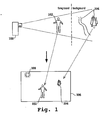
- Figure 1 is a simplified schematic diagram illustrating a scene having foreground and background objects, which is captured through an image capture device and subsequently displayed in accordance with one embodiment of the invention.
- Figure 2 is a simplified schematic diagram illustrating the generation of a depth mask for use in discerning between foreground and background objects in accordance with one embodiment of the invention.
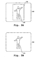
- Figures 3A and 3B are simplified schematic diagrams illustrating the amount of detail enabled in defining foreground objects in accordance with one embodiment of the invention.
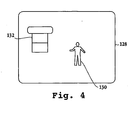
- Figure 4 is a simplified schematic diagram illustrating a captured image which is enhanced through a generated mask to define background and foreground images in accordance with one embodiment of the invention.
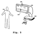
- Figure 5 is a simplified schematic diagram of an interactive entertainment system which utilizes the mask generation in order to more effectively track a user in accordance with one embodiment of the invention.
- FIG. 6 is a simplified schematic diagram of an image capture device in accordance with one embodiment of the invention.
- Figure 7 is an alternative schematic diagram of an image capture device having logic configured to differentiate between foreground and background images in the invention.
- Figure 8 is a flow chart diagram illustrating the method operations for adjusting image capture settings for an image capture device in accordance with one embodiment of the invention.
- An invention for a system and method for differentiating between foreground and background objects of a scene and subsequently adjusting image or video characteristics based upon whether the objects are located in the foreground or background. Alternatively, the image or video characteristics may be adjusted based upon the relatives distance between the objects and the image capture device.
- numerous specific details are set forth in order to provide a thorough understanding of the present invention. It will be apparent, however, to one skilled in the art that the present invention may be practiced without some or all of these specific details. In other instances, well known process steps have not been described in detail in order not to unnecessarily obscure the present invention.
- the embodiments of the present invention provide a method and system that eliminates the user from having to choose between foreground and background objects of a scene.
- the scene may be segmented into regions of different depths.
- the depth information allows for the definition of an exact outline of the image, thereby providing a specific and accurate mechanism for controlling image capture device parameters, e.g., exposure/gain/brightness/gain and focus.
- the segmentation based upon depth information makes it possible to assign different parameter values to different pixel regions for a digital capture device.
- an image having the exposure/gain adjusted properly for both the foreground and background is enabled through the embodiments described below.
- the segmentation based upon depth is captured through a foreground/background depth mask which may be created through an image capture device having depth capability or through a light pulse/flash with a time of flight cut-off technique, both discussed in more detail below.
- FIG. 1 is a simplified schematic diagram illustrating a scene having foreground and background objects which is captured through an image capture device and subsequently displayed in accordance with one embodiment of the invention.
- Image capture device 100 is configured to capture an image of a scene in which a person 102 is in the foreground and background scenery 104. The captured image of the scene is then displayed on display panel 106.
- Display panel 106 may be a display panel affixed to image capture device 100, e.g., a liquid crystal display (LCD) panel where the image capture device is a digital camera or camcorder.
- LCD liquid crystal display
- display panel 106 may be remote from image captures device 100, e.g., a television screen where the image capture device is a webcam used in conjunction with a computing device, such as a game console.
- image captures device 100 e.g., a television screen where the image capture device is a webcam used in conjunction with a computing device, such as a game console.
- foreground image 102 and background scenery 104 are capable of having their corresponding image or video characteristics independently compensated irrespective of their position in either the foreground or the background. While a single foreground image 102 is shown in Figure 1 , it should be appreciated that multiple foreground images may be captured.
- the image or video characteristics for each of the multiple foreground images may be independently adjusted based upon depth information.
- image or video characteristics may refer to brightness, exposure, gain, focus and other suitable characteristics capable of being adjusted for image display.
- image capture device 100 may be a digital still camera, a single lens reflex camera, a video capture device, such as a web cam or camcorder, or any other suitable image capture device.
- Image capture device 100 is capable of generating and utilizing a mask in order to identify objects as being within a foreground or background region as will be described in more detail below.
- This mask can then be used in order to compensate for the foreground and background regions, in order to provide a subsequent display which shows details for objects within both regions.
- the use of backlight compensation to reduce the impact of a bright light source on the scene, such as sun 108 causes details to be defined for foreground objects, i.e., object 102, while the background images are washed out.
- sun 108 is illustrated on display panel 106, it is shown for exemplary purposes and a scene need not include an actual image of the sun to be adversely impacted by the light originating from the sun.
- the exact location of foreground and background and background objects in the scene may be determined. This location may be translated to a resulting image of the scene in order to manipulate corresponding pixel values to enhance the resulting image.
- image capture device settings which include mechanical and electrical settings that affect the image or video characteristics of the resulting image, may be adjusted in order to provide optimized settings for the scene.
- image capture device 100 is a video capture device, e.g., a web cam
- the enhanced functionality enabled through the depth information provided by the mask may be applied to frames of the captured video in order to improve or enhance the image display.
- the mask may be applied to prevent difficulty encountered when tracking the object or person in the presence of a bright light source.
- a video game application in the home environment such as the EYETOY TM application owned by the assignee
- a user being tracked and incorporated into the video game may be positioned in front of a window.
- FIG. 2 is a simplified schematic diagram illustrating the generation of a depth mask for use in discerning between foreground and background objects in accordance with one embodiment of the invention.
- Image capture device 100 includes light source 110.
- light source 110 sends out a burst or pulse of light which is reflected by foreground objects 114 and 116. This reflected light is eventually captured by a sensor located behind lens 112 of image capture device 100.
- light source 110 may be a flash commonly used for cameras.
- the sensor may be located anywhere on image capture device 100 that is capable of receiving the reflected light from the foreground objects within the scene for a defined time period.
- image capture device 100 of Figure 2 may be configured to pulse the burst of light from light source 110 and open an aperture of image capture device 100 so that the reflected light from the foreground objects is received.
- the aperture will stay open for a predefined amount of time.
- the predefined amount of time is set so that light traveling from light source 110 and reflected back to image capture device 100, travels a defined maximum amount of distance.
- the maximum distance from image capture device 100 is illustrated as line 117. Therefore, any light which is reflected from a source past line 117 will not be received by image capture device as the aperture is closed prior to this reflected light reaching the sensor of the image capture device.
- the ambient light i.e., the light not generated by the burst of light from the light source, is subtracted from the received light.
- Various techniques may be used for the determining the foreground objects through the time of flight.
- One technique is through the use of a frequency of light not present in the ambient light.
- an image of the scene may be taken without the light on, then an image taken with the light from the light source.
- the light generated by the light source may then be determined by subtracting away the light not generated from the light source, i.e., the image taken without the light on, from the image taken with the light source.
- the amount of light reflected from the light source may be distinguished from ambient light by establishing a threshold of how much light must strike each pixel.
- a value which is less than the threshold would not be considered as light originating from the device and values greater than or equal to the threshold would be considered as originating from the light source of the device.
- the light from the light source is generated in a modulated format, e.g., a sine wave.
- the frequency chosen depends upon a range where no more than one period of the modulation covers the entire range from the light source and back to the device.
- the maximum amount of distance is defined as about four meters from the image capture device. From this data, a depth mask is created and stored in memory of the image capture device. This depth mask may then be used in conjunction with a simultaneous or subsequent captured image of the scene in order to compensate for the image or video characteristics for the foreground and background objects accordingly.
- light source 110 may emit any suitable wavelength of light. In one embodiment, infrared light is emitted from light source 110.
- the depth mask defined through the reflected light is a binary bit mask.
- a first logical value is assigned to locations in the mask associated with foreground images, while a second logical value is assigned to locations associated with background images.
- image capture device 100 is a digital device
- pixel data for an image associated with the depth mask may be manipulated to adjust the brightness of the foreground and background images.
- image capture device is a traditional camera
- foreground and background images may be detected through the burst of light scheme described above. Based on the detection of the foreground and background images, the exposure, gain, brightness, focus, etc., settings of the camera may be adjusted prior to taking a picture of the scene.
- the aperture size may be changed to manipulate the amount of light received by the image capture device.
- other mechanical and electrical settings may be adjusted where the mechanical or electrical settings impact the resulting photograph quality.
- both the foreground and background properties may be adjusted rather than having to choose between the foreground and the background.
- Figures 3A and 3B are simplified schematic diagrams illustrating the amount of detail enabled in defining foreground objects in accordance with one embodiment of the invention.
- Figure 3A illustrates display screen 120 having a foreground object defined through rectangular region 122.
- Figure 3B shows display screen 120 illustrating a foreground object 124 in which a mask has been defined, as described herein, in order to capture the exact outline of the foreground image. That is, with current auto focus, auto gain, backlight compensation techniques, the center of a scene in which an image capture device is targeting, is generally represented as an area and is incapable of outlining the exact image.
- rectangular region 122 includes the foreground object as well as other image data.
- the foreground object must be within a center region of the image or the auto focus, auto gain, or backlight compensation features will not work.
- the depth mask captures any foreground object irrespective of its location within the scene.
- the foreground object is captured without any additional image data being included.
- the image or video characteristics for any foreground object may be manipulated by adjusting pixel values.
- the gain, exposure, focus, and brightness may be manipulated through mechanical or electrical adjustments responsive to the depth mask.
- FIG. 4 is a simplified schematic diagram illustrating a captured image which is enhanced through a mask generated to define background and foreground images in accordance with one embodiment of the invention.
- image scene 128 may be a scene captured through an image capture device such as a video cam or a web cam for an interactive gaming application where participant 130 is incorporated into the interactive gaming application.
- An exemplary interactive gaming application is the EYETOY TM interactive game application.
- participant 130 is standing in front of a web cam or some other suitable video capture device. Behind participant 130 is window 132. It should be appreciated that where bright light is shining through window 132, the resulting image of participant 130 captured by the image capture device will become darkened.
- a mask generated as described above may be used to manipulate the pixel values to reduce the brightness.
- FIG. 5 is a simplified schematic diagram of an interactive entertainment system which utilizes the generated mask in order to more effectively track a user in accordance with one embodiment of the invention.
- image capture device 100 is configured to capture an image of user 134 in order for the user's image to be displayed on display screen 136.
- Image capture device 100 is in communication with computing device 138, which in turn, is in communication with display screen 136.
- image 135 of user 134 is displayed on display screen 136.
- the image capture device is configured to compensate for bright light entering through window 132.
- image capture device 100 is a video capture device.
- the pixel data associated with each video frame may be adjusted according to a corresponding depth mask.
- a depth mask is generated for each video frame.
- the depth mask is generated every x number of frames, where x may be any integer.
- the image or video characteristics from the last previous frame associated with a mask are applied to the frames not associated with a mask.
- the image or video characteristics may be frozen for a certain number of frames until a new mask is generated.
- the processing for the functionality described herein may be performed by a processor of computing device 138.
- the depth mask may be generated by image capture device 100 and stored in memory of the image capture device.
- the image capture device would contain a microprocessor for executing the functionality for generating the depth mask and adjusting the image or video characteristics or adjusting the device parameters.
- Image capture, device 100 of Figure 5 may generate the mask through the techniques described with reference to Figure 2 , however, image capture device 100 may alternatively include depth capturing logic, such as 3DV SYSTEM's ZCAM TM or similar products commercially available through CANESTA TM .
- the depth capturing logic includes an image sensor that captures the depth value of each pixel in a scene in order to create a depth mask to be used as discussed herein. It should be noted that while a single user 134 is depicted in Figure 5 , it should be noted that multiple users may be incorporated in the embodiments described here.
- FIG. 6 is a simplified schematic diagram of an image capture device in accordance with one embodiment of the invention.
- Image capture device 100 includes depth logic 140, image capture device logic 142, and memory 144 all in communication with each other.
- depth logic 140 includes circuitry configured to generate a mask in order for image capture device 100 to enhance a captured image with the assistance of the depth information.
- depth logic 140 may generate the mask in order to differentiate between foreground and background objects within an image scene, and this mask will be stored in memory 144. Then, a corresponding scene of the image that is captured and processed by image capture device logic 142 will be enhanced. That is, certain image or video characteristics are manipulated as described herein depending on whether an object within the scene is located in the foreground or background, as determined by the depth mask.
- depth logic 140 is activated by button 141 or some other suitable activation mechanism. Thus, a user has the option of activating the depth logic for enhanced image presentation, or bypassing the image presentation.
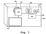
- FIG. 7 is an alternative schematic diagram of an image capture device having logic configured to differentiate between foreground and background images in the invention.
- Image capture device 100 includes lens 150 behind which is charged coupled device (CCD) 152.
- Depth logic 140, microprocessor unit (MPU) 148, and memory 144 are also included.
- Image capture device 100 includes display panel 154. It will be apparent to one skilled in the art that while image capture device 100 is depicted as a digital camera in Figure 7 , the invention is not limited to a digital camera.
- Depth logic module 140 may be included in a video capture device in order to adjust image or video characteristics of each frame or every x th frame.
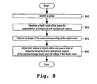
- Figure 8 is a flow chart diagram illustrating the method operations for adjusting image capture settings for an image capture device in accordance with one embodiment of the invention.
- the method initiates with operation 160 where a scene is identified.
- an image capture device may be used to identify a scene defined by a capture region.
- the image capture device may be a video capture device.
- the method then advances to operation 162 where a depth mask of the scene is generated for segmentation of foreground and background regions.
- the depth mask is generated by pulsing light and capturing reflections from an object within a certain distance as described with reference to Figure 2 .
- the light may be infrared light.
- the image capture device includes depth logic capable of capturing a depth value for each pixel.
- One exemplary image capture device with depth logic is the ZCAM TM mentioned above.
- the method then proceeds to operation 164 where an image of the scene is captured and this captured image corresponds to the depth mask. It should be appreciated that for the ZCAM TM embodiment, operations 162 and 164 are performed simultaneously.
- the method then moves to operation 166 where pixel values of objects within either, or both, of the foreground and background regions of the captured image are adjusted. This adjustment is based upon the depth mask defined above.
- the depth mask may be defined through bit values where a first bit value is assigned to foreground objects and a second bit value is assigned to background objects. The adjustment then enhances the brightness of foreground objects while decreasing the brightness of background objects where a bright light source exists in one embodiment.
- the image capture device is not a digital device, e.g., a SLR camera
- mechanical or electrical adjustments of the image capture device parameters may be made as a result of the foreground and background objects identified by the bit mask. These mechanical or electrical adjustments may include defining an aperture size corresponding to a certain exposure level, lens settings for a particular focus level, etc.
- the pixel values are adjusted according to depth information included with the image data, i.e., distance information tagged to each pixel of the image data.
- depth information included with the image data i.e., distance information tagged to each pixel of the image data.
- the aperture size may be controlled mechanically or electronically.
- the electronic control may be performed through a sensor on a chip. Thus, each pixel adjusted separately with the electronic control.
- an image capture device capable of generating a depth mask for corresponding segments of a scene. It should be appreciated that while the invention has been described in terms of the background and foreground segments (2 layers) of a scene, the embodiments described herein may be extended to any number of layers of the scene. Through the depth mask, the image or video characteristics for an image may be selectively adjusted irrespective of where an object is located in the scene. Furthermore, the capture device described herein enables enhanced functionality for interactive entertainment applications. For example, with respect to a video game application, where a user is tracked to incorporate his image into the video game, the capture device described above enables for enhanced tracking of the user. The user is free to move anywhere in the capture region and is not limited to one area, such as a center region.
- the adjustments may be applied every interval of frames in order to avoid constant adjustments from occurring. For example, if a user briefly holds up a black piece of paper in front of him, the frame interval delay will prevent the user from suddenly turning darker. Also, if the user temporarily leaves the field of view of the image capture device and comes back, the adjustment and re-adjustment of the scene is avoided.
- the embodiments described above may be extended to other systems in addition to an interactive entertainment input device, i.e., the EYETOY TM system capture device.
- the video capture device may be used in a videoconferencing system to provide enhanced video images for the conference.
- the capture device may not be used for tracking purposes, but for the enhancement of the image or video characteristics enabled through the depth information.
- the invention may employ various computer-implemented operations involving data stored in computer systems. These operations are those requiring physical manipulation of physical quantities. Usually, though not necessarily, these quantities take the form of electrical or magnetic signals capable of being stored, transferred, combined, compared, and otherwise manipulated. Further, the manipulations performed are often referred to in terms, such as producing, identifying, determining, or comparing.
- the invention also relates to a device or an apparatus for performing these operations.
- the apparatus may be specially constructed for the required purposes, or it may be a general purpose computer selectively activated or configured by a computer program stored in the computer.
- various general purpose machines may be used with computer programs written in accordance with the teachings herein, or it may be more convenient to construct a more specialized apparatus to perform the required operations.
Landscapes
- Engineering & Computer Science (AREA)
- Multimedia (AREA)
- Signal Processing (AREA)
- Computer Vision & Pattern Recognition (AREA)
- Image Processing (AREA)
- Studio Devices (AREA)
- Image Analysis (AREA)
- Exposure Control For Cameras (AREA)
- Focusing (AREA)
- Automatic Focus Adjustment (AREA)
Abstract
Description
- This invention relates generally to image capture techniques, and more particularly to enhancing a captured image of a scene by adjustments enabled through depth information.
- Image capture devices, whether cameras or video based devices, typically have a limited contrast ratio, which is a measure of the difference between the darkest and lightest parts of a scene. One exemplary scene may include a person in the shade and the background having bright sunlight. When the background of this scene is exposed correctly for the image capture device, there is little or no detail in the shaded person's face.
- Auto-exposure and auto-gain features are commonly used to set brightness levels for the capture device. These features tend to take the entire scene and average it to apply a certain exposure or gain setting. While the averaging may work well for a scene having a great deal of images and colors, this scheme quickly breaks down as the scene has less variety.
- One attempt to address the limited contrast ratio of current capture devices is through the use of a backlight feature. For instance, where there is a bright light source in the background, e.g., sunlight, backlight compensation will take the center of the scene and use that region as the average. By doing this, the center of the scene may be brightened while the bright sunlight on the edges becomes washed out or darkened. The shortcoming with backlight compensation is that the object to be brightened must be in the center of the scene. In addition, a region of the scene is used for computing the average, rather than the actual object itself, which may cause some display artifacts. Furthermore, backlight compensation does not provide a solution where there are multiple foreground images in different regions of the scene. Additionally, with backlight compensation, the foreground object is brightened, however, this is done at the expense of the detail in the background. Thus, a user is required to choose between foreground detail and background detail. Some of these shortcomings may be extended to video capture devices which may be used for interactive entertainment applications. For example, where an image of a user is incorporated into a video game, a bright light source may adversely the displayed image as described above. This adverse impact may prevent the tracking of an object of the image in addition to displaying a poor quality image.
- Accordingly, there is a need to solve the problems of the prior art to provide a system and method for producing an image that has the exposure/gain and other related parameters adjusted for both the foreground and background.
- Broadly speaking, the present invention fills these needs by providing a method and system that enables adjustment of segments of a scene, e.g., foreground and background images, where the foreground and background images are identified through a depth mask. It should be appreciated that the present invention can be implemented in numerous ways, including as a process, a system, or a device. Several inventive embodiments of the present invention are described below.
- In one embodiment, a method for differentiating between foreground objects and background objects within a scene being captured through an image capture device is provided. The method initiates with emitting a ray of light from a light source toward an object of the scene. The method includes opening an aperture cover allowing access to a sensor of the image capture device for reflected light from the light source. Then, the aperture cover is closed after a predefined time, where the predefined amount of time corresponds to a maximum distance traveled by the light. Next, a depth mask identifying objects within a foreground region of the scene is generated based upon the light captured during the predefined time. Then, image capture device parameters are adjusted according to bit values of the depth mask prior to capturing a subsequent corresponding image of the scene.
- In another embodiment, a method for adjusting image capture settings for an image capture device is provided. The method initiates with identifying a scene. Then, an image of the scene is captured. The method includes generating a depth mask of the scene from data defining the image of the scene. Then, pixel values corresponding to objects within any one or both of a foreground region and a background region of the captured image are adjusted based upon bit values of the depth mask.
- In yet another embodiment, an image capture device configured to capture an image of a scene is provided. The image capture device includes depth logic configured to provide a depth mask associated with the scene. The depth mask is configured to distinguish between foreground objects and background objects within the scene. The image capture device also includes image capture logic configured to adjust a characteristic associated with the image based upon a corresponding bit value of the depth mask. The bit value determines whether the respective pixel is associated with one of the foreground objects and the background objects.
- In still yet another embodiment, a system is provided. The system includes a computing device and a display screen in communication with the computing device. The display screen is configured to display an image of a scene. A video capture device in communication with the computing device is included. The video capture device provides scene image data to the computing device for presentation on the display screen. The video capture device includes depth logic and image capture logic. The depth logic is configured to provide a depth mask associated with the scene. The depth mask is configured to distinguish between foreground objects and background objects within the scene. The image capture logic is configured to adjust a characteristic associated with each pixel of the image data based upon corresponding data of the depth mask. The data of the depth mask determines a relative distance between an object associated with the corresponding pixel and the video capture device.
- Other aspects and advantages of the invention will become apparent from the following detailed description, taken in conjunction with the accompanying drawings, illustrating by way of example the principles of the invention.
- The invention, together with further advantages thereof, may best be understood by reference to the following description taken in conjunction with the accompanying drawings.
-
Figure 1 is a simplified schematic diagram illustrating a scene having foreground and background objects, which is captured through an image capture device and subsequently displayed in accordance with one embodiment of the invention. -
Figure 2 is a simplified schematic diagram illustrating the generation of a depth mask for use in discerning between foreground and background objects in accordance with one embodiment of the invention. -
Figures 3A and 3B are simplified schematic diagrams illustrating the amount of detail enabled in defining foreground objects in accordance with one embodiment of the invention. -
Figure 4 is a simplified schematic diagram illustrating a captured image which is enhanced through a generated mask to define background and foreground images in accordance with one embodiment of the invention. -
Figure 5 is a simplified schematic diagram of an interactive entertainment system which utilizes the mask generation in order to more effectively track a user in accordance with one embodiment of the invention. -
Figure 6 is a simplified schematic diagram of an image capture device in accordance with one embodiment of the invention. -
Figure 7 is an alternative schematic diagram of an image capture device having logic configured to differentiate between foreground and background images in the invention. -
Figure 8 is a flow chart diagram illustrating the method operations for adjusting image capture settings for an image capture device in accordance with one embodiment of the invention. - An invention is disclosed for a system and method for differentiating between foreground and background objects of a scene and subsequently adjusting image or video characteristics based upon whether the objects are located in the foreground or background. Alternatively, the image or video characteristics may be adjusted based upon the relatives distance between the objects and the image capture device. In the following description, numerous specific details are set forth in order to provide a thorough understanding of the present invention. It will be apparent, however, to one skilled in the art that the present invention may be practiced without some or all of these specific details. In other instances, well known process steps have not been described in detail in order not to unnecessarily obscure the present invention.
- The embodiments of the present invention provide a method and system that eliminates the user from having to choose between foreground and background objects of a scene. Through the use of depth information, the scene may be segmented into regions of different depths. In addition, the depth information allows for the definition of an exact outline of the image, thereby providing a specific and accurate mechanism for controlling image capture device parameters, e.g., exposure/gain/brightness/gain and focus. The segmentation based upon depth information makes it possible to assign different parameter values to different pixel regions for a digital capture device. Thus, an image having the exposure/gain adjusted properly for both the foreground and background is enabled through the embodiments described below. The segmentation based upon depth is captured through a foreground/background depth mask which may be created through an image capture device having depth capability or through a light pulse/flash with a time of flight cut-off technique, both discussed in more detail below.
-
Figure 1 is a simplified schematic diagram illustrating a scene having foreground and background objects which is captured through an image capture device and subsequently displayed in accordance with one embodiment of the invention.Image capture device 100 is configured to capture an image of a scene in which aperson 102 is in the foreground andbackground scenery 104. The captured image of the scene is then displayed ondisplay panel 106.Display panel 106 may be a display panel affixed to imagecapture device 100, e.g., a liquid crystal display (LCD) panel where the image capture device is a digital camera or camcorder. Alternatively,display panel 106 may be remote from image capturesdevice 100, e.g., a television screen where the image capture device is a webcam used in conjunction with a computing device, such as a game console. As will be described in more detail below,foreground image 102 andbackground scenery 104 are capable of having their corresponding image or video characteristics independently compensated irrespective of their position in either the foreground or the background. While asingle foreground image 102 is shown inFigure 1 , it should be appreciated that multiple foreground images may be captured. The image or video characteristics for each of the multiple foreground images may be independently adjusted based upon depth information. As used herein, image or video characteristics may refer to brightness, exposure, gain, focus and other suitable characteristics capable of being adjusted for image display. It should be appreciated that image or video characteristics may be referred to simply as characteristics and correspond to the inherent image data which improves the display quality of the image data through the embodiments described herein. Additionally,image capture device 100 may be a digital still camera, a single lens reflex camera, a video capture device, such as a web cam or camcorder, or any other suitable image capture device. -
Image capture device 100, ofFigure 1 , is capable of generating and utilizing a mask in order to identify objects as being within a foreground or background region as will be described in more detail below. This mask can then be used in order to compensate for the foreground and background regions, in order to provide a subsequent display which shows details for objects within both regions. For example, the use of backlight compensation to reduce the impact of a bright light source on the scene, such assun 108, causes details to be defined for foreground objects, i.e.,object 102, while the background images are washed out. Whilesun 108 is illustrated ondisplay panel 106, it is shown for exemplary purposes and a scene need not include an actual image of the sun to be adversely impacted by the light originating from the sun. Without backlight compensation, foreground objects would be darkened and lose their corresponding detail in the resulting display. With the depth mask capability described in more detail below, the exact location of foreground and background and background objects in the scene may be determined. This location may be translated to a resulting image of the scene in order to manipulate corresponding pixel values to enhance the resulting image. In addition, image capture device settings, which include mechanical and electrical settings that affect the image or video characteristics of the resulting image, may be adjusted in order to provide optimized settings for the scene. - Where
image capture device 100 is a video capture device, e.g., a web cam, the enhanced functionality enabled through the depth information provided by the mask may be applied to frames of the captured video in order to improve or enhance the image display. For example, where the video capture device is used to track an object or person subsequently incorporated into an interactive entertainment application, the mask may be applied to prevent difficulty encountered when tracking the object or person in the presence of a bright light source. With respect to a video game application in the home environment, such as the EYETOY™ application owned by the assignee, a user being tracked and incorporated into the video game may be positioned in front of a window. As explained below in more detail with reference toFigure 4 , if the window is allowing light from a bright light source through the window, then the user may become washed out and the window will become the focus of the capture device. It should be appreciated that backlight compensation techniques will not be effective here if the user is not in the center of the capture region. -
Figure 2 is a simplified schematic diagram illustrating the generation of a depth mask for use in discerning between foreground and background objects in accordance with one embodiment of the invention. It should be noted that the terms "depth mask" and "mask" are interchangeable as used herein and may include multiple depth layers. For example, the foreground and the background represent 2 depth layers, however, the scene may be segmented into more than two depth layers.Image capture device 100 includeslight source 110. In one embodiment,light source 110 sends out a burst or pulse of light which is reflected byforeground objects lens 112 ofimage capture device 100. Of course,light source 110 may be a flash commonly used for cameras. One skilled in the art will appreciate that the sensor may be located anywhere onimage capture device 100 that is capable of receiving the reflected light from the foreground objects within the scene for a defined time period. - As the speed of light is known,
image capture device 100 ofFigure 2 may be configured to pulse the burst of light fromlight source 110 and open an aperture ofimage capture device 100 so that the reflected light from the foreground objects is received. The aperture will stay open for a predefined amount of time. The predefined amount of time is set so that light traveling fromlight source 110 and reflected back toimage capture device 100, travels a defined maximum amount of distance. The maximum distance fromimage capture device 100 is illustrated asline 117. Therefore, any light which is reflected from a sourcepast line 117 will not be received by image capture device as the aperture is closed prior to this reflected light reaching the sensor of the image capture device. Of course, the ambient light, i.e., the light not generated by the burst of light from the light source, is subtracted from the received light. - Various techniques may be used for the determining the foreground objects through the time of flight. One technique is through the use of a frequency of light not present in the ambient light. Alternatively, an image of the scene may be taken without the light on, then an image taken with the light from the light source. The light generated by the light source may then be determined by subtracting away the light not generated from the light source, i.e., the image taken without the light on, from the image taken with the light source. In yet another alternative, the amount of light reflected from the light source may be distinguished from ambient light by establishing a threshold of how much light must strike each pixel. Thus, a value which is less than the threshold would not be considered as light originating from the device and values greater than or equal to the threshold would be considered as originating from the light source of the device. Still yet another alternative that employs the use of a modulated light source. Here, the light from the light source is generated in a modulated format, e.g., a sine wave. The frequency chosen depends upon a range where no more than one period of the modulation covers the entire range from the light source and back to the device.
- In one embodiment, the maximum amount of distance is defined as about four meters from the image capture device. From this data, a depth mask is created and stored in memory of the image capture device. This depth mask may then be used in conjunction with a simultaneous or subsequent captured image of the scene in order to compensate for the image or video characteristics for the foreground and background objects accordingly. It will be apparent to one skilled in the art that
light source 110 may emit any suitable wavelength of light. In one embodiment, infrared light is emitted fromlight source 110. - In another embodiment, the depth mask defined through the reflected light is a binary bit mask. Here, a first logical value is assigned to locations in the mask associated with foreground images, while a second logical value is assigned to locations associated with background images. Thus, where
image capture device 100 is a digital device, pixel data for an image associated with the depth mask may be manipulated to adjust the brightness of the foreground and background images. Where image capture device is a traditional camera, foreground and background images may be detected through the burst of light scheme described above. Based on the detection of the foreground and background images, the exposure, gain, brightness, focus, etc., settings of the camera may be adjusted prior to taking a picture of the scene. As mentioned above, the aperture size may be changed to manipulate the amount of light received by the image capture device. Of course, other mechanical and electrical settings may be adjusted where the mechanical or electrical settings impact the resulting photograph quality. Thus, both the foreground and background properties may be adjusted rather than having to choose between the foreground and the background. -
Figures 3A and 3B are simplified schematic diagrams illustrating the amount of detail enabled in defining foreground objects in accordance with one embodiment of the invention.Figure 3A illustratesdisplay screen 120 having a foreground object defined throughrectangular region 122.Figure 3B showsdisplay screen 120 illustrating aforeground object 124 in which a mask has been defined, as described herein, in order to capture the exact outline of the foreground image. That is, with current auto focus, auto gain, backlight compensation techniques, the center of a scene in which an image capture device is targeting, is generally represented as an area and is incapable of outlining the exact image. Thus, as illustrated inFigure 3A ,rectangular region 122 includes the foreground object as well as other image data. Furthermore, the foreground object must be within a center region of the image or the auto focus, auto gain, or backlight compensation features will not work. In contrast, the depth mask captures any foreground object irrespective of its location within the scene. Moreover, the foreground object is captured without any additional image data being included. As mentioned above, for a digital device, the image or video characteristics for any foreground object may be manipulated by adjusting pixel values. With respect to a traditional film camera, the gain, exposure, focus, and brightness may be manipulated through mechanical or electrical adjustments responsive to the depth mask. -
Figure 4 is a simplified schematic diagram illustrating a captured image which is enhanced through a mask generated to define background and foreground images in accordance with one embodiment of the invention. Here,image scene 128 may be a scene captured through an image capture device such as a video cam or a web cam for an interactive gaming application whereparticipant 130 is incorporated into the interactive gaming application. An exemplary interactive gaming application is the EYETOY™ interactive game application. Here,participant 130 is standing in front of a web cam or some other suitable video capture device. Behindparticipant 130 iswindow 132. It should be appreciated that where bright light is shining throughwindow 132, the resulting image ofparticipant 130 captured by the image capture device will become darkened. In an interactive video game application where tracking the user is important, the tracking will become difficult where the bright light darkens the image of the user. Thus, where the video cam incorporates the embodiments described herein, the user will be able to be tracked more easily. That is, a mask generated as described above, may be used to manipulate the pixel values to reduce the brightness. -
Figure 5 is a simplified schematic diagram of an interactive entertainment system which utilizes the generated mask in order to more effectively track a user in accordance with one embodiment of the invention. Here,image capture device 100 is configured to capture an image ofuser 134 in order for the user's image to be displayed ondisplay screen 136.Image capture device 100 is in communication withcomputing device 138, which in turn, is in communication withdisplay screen 136. As can be seen, image 135 ofuser 134 is displayed ondisplay screen 136. Thus, asuser 134 moves, this movement is captured throughimage capture device 100 and displayed ondisplay screen 136 in order to interact with the entertainment application. As mentioned above, the image capture device is configured to compensate for bright light entering throughwindow 132. - Still referring to
Figure 5 ,image capture device 100 is a video capture device. Here, the pixel data associated with each video frame may be adjusted according to a corresponding depth mask. In one embodiment, a depth mask is generated for each video frame. In another embodiment, the depth mask is generated every x number of frames, where x may be any integer. For the frames not associated with a mask in this embodiment, the image or video characteristics from the last previous frame associated with a mask are applied to the frames not associated with a mask. Thus, the image or video characteristics may be frozen for a certain number of frames until a new mask is generated. It will be apparent to one skilled in the art that the processing for the functionality described herein may be performed by a processor ofcomputing device 138. However, the depth mask may be generated byimage capture device 100 and stored in memory of the image capture device. Of course, the image capture device would contain a microprocessor for executing the functionality for generating the depth mask and adjusting the image or video characteristics or adjusting the device parameters. - Image capture,
device 100 ofFigure 5 may generate the mask through the techniques described with reference toFigure 2 , however,image capture device 100 may alternatively include depth capturing logic, such as 3DV SYSTEM's ZCAM™ or similar products commercially available through CANESTA™. The depth capturing logic includes an image sensor that captures the depth value of each pixel in a scene in order to create a depth mask to be used as discussed herein. It should be noted that while asingle user 134 is depicted inFigure 5 , it should be noted that multiple users may be incorporated in the embodiments described here. Since the depth mask enables adjustment of both foreground and background object image or video characteristics, it is not required thatuser 134 be located in the middle or any other particular area of the capture region for image capturesdevice 100. It should be further appreciated that one exemplary system represented byFigure 5 is the EYETOY™ system mentioned above. -
Figure 6 is a simplified schematic diagram of an image capture device in accordance with one embodiment of the invention.Image capture device 100 includesdepth logic 140, imagecapture device logic 142, andmemory 144 all in communication with each other. As described herein,depth logic 140 includes circuitry configured to generate a mask in order forimage capture device 100 to enhance a captured image with the assistance of the depth information. For example,depth logic 140 may generate the mask in order to differentiate between foreground and background objects within an image scene, and this mask will be stored inmemory 144. Then, a corresponding scene of the image that is captured and processed by imagecapture device logic 142 will be enhanced. That is, certain image or video characteristics are manipulated as described herein depending on whether an object within the scene is located in the foreground or background, as determined by the depth mask. In one embodiment,depth logic 140 is activated bybutton 141 or some other suitable activation mechanism. Thus, a user has the option of activating the depth logic for enhanced image presentation, or bypassing the image presentation. -
Figure 7 is an alternative schematic diagram of an image capture device having logic configured to differentiate between foreground and background images in the invention.Image capture device 100 includeslens 150 behind which is charged coupled device (CCD) 152.Depth logic 140, microprocessor unit (MPU) 148, andmemory 144 are also included.Image capture device 100 includesdisplay panel 154. It will be apparent to one skilled in the art that whileimage capture device 100 is depicted as a digital camera inFigure 7 , the invention is not limited to a digital camera.Depth logic module 140 may be included in a video capture device in order to adjust image or video characteristics of each frame or every xth frame. -
Figure 8 is a flow chart diagram illustrating the method operations for adjusting image capture settings for an image capture device in accordance with one embodiment of the invention. The method initiates withoperation 160 where a scene is identified. Here, an image capture device may be used to identify a scene defined by a capture region. Of course, the image capture device may be a video capture device. The method then advances tooperation 162 where a depth mask of the scene is generated for segmentation of foreground and background regions. In one embodiment, the depth mask is generated by pulsing light and capturing reflections from an object within a certain distance as described with reference toFigure 2 . Here the light may be infrared light. In another embodiment, the image capture device includes depth logic capable of capturing a depth value for each pixel. One exemplary image capture device with depth logic is the ZCAM™ mentioned above. The method then proceeds tooperation 164 where an image of the scene is captured and this captured image corresponds to the depth mask. It should be appreciated that for the ZCAM™ embodiment,operations operation 166 where pixel values of objects within either, or both, of the foreground and background regions of the captured image are adjusted. This adjustment is based upon the depth mask defined above. - For example, the depth mask may be defined through bit values where a first bit value is assigned to foreground objects and a second bit value is assigned to background objects. The adjustment then enhances the brightness of foreground objects while decreasing the brightness of background objects where a bright light source exists in one embodiment. Where the image capture device is not a digital device, e.g., a SLR camera, mechanical or electrical adjustments of the image capture device parameters may be made as a result of the foreground and background objects identified by the bit mask. These mechanical or electrical adjustments may include defining an aperture size corresponding to a certain exposure level, lens settings for a particular focus level, etc. In another embodiment, the pixel values are adjusted according to depth information included with the image data, i.e., distance information tagged to each pixel of the image data. One skilled in the art will appreciate that the aperture size may be controlled mechanically or electronically. The electronic control may be performed through a sensor on a chip. Thus, each pixel adjusted separately with the electronic control.
- In summary, an image capture device capable of generating a depth mask for corresponding segments of a scene is provided. It should be appreciated that while the invention has been described in terms of the background and foreground segments (2 layers) of a scene, the embodiments described herein may be extended to any number of layers of the scene. Through the depth mask, the image or video characteristics for an image may be selectively adjusted irrespective of where an object is located in the scene. Furthermore, the capture device described herein enables enhanced functionality for interactive entertainment applications. For example, with respect to a video game application, where a user is tracked to incorporate his image into the video game, the capture device described above enables for enhanced tracking of the user. The user is free to move anywhere in the capture region and is not limited to one area, such as a center region. Additionally, as the user moves in front of a bright light source, e.g., sunlight coming through a window, the detail of the user's image is not lost. With respect to a video capture device, the adjustments may be applied every interval of frames in order to avoid constant adjustments from occurring. For example, if a user briefly holds up a black piece of paper in front of him, the frame interval delay will prevent the user from suddenly turning darker. Also, if the user temporarily leaves the field of view of the image capture device and comes back, the adjustment and re-adjustment of the scene is avoided.
- It should be appreciated that the embodiments described above may be extended to other systems in addition to an interactive entertainment input device, i.e., the EYETOY™ system capture device. For example, the video capture device may be used in a videoconferencing system to provide enhanced video images for the conference. Here, the capture device may not be used for tracking purposes, but for the enhancement of the image or video characteristics enabled through the depth information.
- The invention may employ various computer-implemented operations involving data stored in computer systems. These operations are those requiring physical manipulation of physical quantities. Usually, though not necessarily, these quantities take the form of electrical or magnetic signals capable of being stored, transferred, combined, compared, and otherwise manipulated. Further, the manipulations performed are often referred to in terms, such as producing, identifying, determining, or comparing.
- Any of the operations described herein that form part of the invention are useful machine operations. The invention also relates to a device or an apparatus for performing these operations. The apparatus may be specially constructed for the required purposes, or it may be a general purpose computer selectively activated or configured by a computer program stored in the computer. In particular, various general purpose machines may be used with computer programs written in accordance with the teachings herein, or it may be more convenient to construct a more specialized apparatus to perform the required operations.
- Although the foregoing invention has been described in some detail for purposes of clarity of understanding, it will be apparent that certain changes and modifications may be practiced. Accordingly, the present embodiments are to be considered as illustrative and not restrictive, and the invention is not to be limited to the details given herein, but may be modified within the scope and equivalents of the description.
Further embodiments of the invention are disclosed in the following numbered clauses: - 1. A method for differentiating between foreground objects and background objects within a scene being captured through an image capture device, comprising:
- emitting a ray of light from a light source toward an object of the scene;
- opening an aperture cover allowing access to a sensor of the image capture device for reflected light from the light source;
- closing the aperture cover after a set time, the predefined amount of time corresponding to a maximum distance traveled by the light;
- generating a depth mask identifying objects within a foreground region of the scene based upon the light captured during the set time; and
- adjusting image capture device parameters according to bit values of the depth mask prior to capturing a subsequent corresponding image of the scene.
- 2. The method of clause 1, further comprising:
- storing the depth mask in memory of the image capture device.
- 3. The method of clause 1, wherein the light source is configured to emit infrared light,
- 4. The method of clause 1, wherein the method operation of opening an aperture cover allowing access to a sensor of the image capture device includes,
receiving reflected light from the objects within the foreground region. - 5. The method of clause 1, wherein the method operation of generating a depth mask identifying obj ects within a foreground region of the scene based upon the light captured during the predefined time includes,
identifying objects within the foreground region with a first bit value; and identifying objects within a background region with a second bit value. - 6. The method of clause 1, wherein the method operation of adjusting image capture device parameters according to bit values of the depth mask prior to capturing a subsequent corresponding image of the scene includes,
determining an optimal amount of light based upon the depth mask; and adjusting the aperture cover to allow the optimal amount of light into the image capture device. - 7. The method of clause 1, wherein the image capture device parameters are selected from the group consisting of focus, brightness, exposure, and gain.
- 8. The method operation of clause 1,wherein the method operation of emitting a ray of light from a light source toward an object of the scene includes,
pulsing infrared light from the light source. - 9. A method for adjusting image capture settings for an image capture device, comprising:
- identifying a scene;
- capturing an image of the scene;
- generating a depth mask of the scene from data defining the image of the scene;
and - adjusting pixel values corresponding to objects within any one or both of a foreground region and a background region of the captured image.
- 10. The method of clause 9, wherein the method operation of generating a depth mask of the scene from data defining the image of the scene includes,
segmenting the foreground and background regions of the scene. - 11. The method of clause 9, wherein the data defining the image of the scene includes pixel data where each pixel is tagged with distance information.
- 12. The method of clause 9, wherein the method operation of adjusting pixel values corresponding to objects within any one or both of a foreground region and a background region of the captured image based upon bit values of the depth mask includes,
independently adjusting pixel values associated with the foreground region from pixel values associated with the background region. - 13. The method of clause 9, wherein the image capture device is selected from the group consisting of a digital camera, a web cam, and a camcorder.
- 14. The method of clause 9, further comprising:
- displaying a portion of the image of the scene having adjusted pixel values.
- 15. The method of clause 14, wherein the portion of the image of the scene is an image of a participant for use in an interactive gaming application.
- 16. The method of clause 9, wherein the method operation of adjusting pixel values corresponding to objects within any one or both of a foreground region and a background region of the captured image includes,
adjusting the pixel values according to bit values of the depth mask. - 17. An image capture device configured to provide an image of a scene, comprising:
- depth logic configured to provide a depth mask associated with the scene, the depth mask configured to distinguish between foreground objects and background objects within the scene; and image capture logic configured to adjust a characteristic associated with the image based upon a corresponding bit value of the depth mask, wherein the bit value determines whether the respective pixel is associated with one of the foreground objects and the background objects.
- 18. The image capture device of clause 17, wherein the depth mask is a bit mask having a first logical value assigned to represent the foreground objects and a second logical value assigned to represent the background objects.
- 19. The image capture device of clause 17, further comprising:
- a sensor in communication with the depth logic, the sensor configured to receive a light signal reflected from one of the foreground objects, the receipt of the light signal indicating a location corresponding to one of the foreground objects.
- 20. The image capture device of clause 17, wherein each logic element is one or a combination of hardware and software.
- 21. The image capture device of clause 17, wherein the image capture device is a video capture device.
- 22. The image capture device of clause 21, wherein the depth logic is further configured to periodically provide a depth mask for a sequence of video frames captured by the video capture device
- 23. The image capture device of clause 17, wherein the characteristic is selected from the group consisting of exposure, gain, focus and brightness.
- 24. The image capture device of clause 17, wherein the image capture logic is further configured to adjust each pixel of image data of the scene.
- 25. A system, comprising:
- a computing device;
- a display screen in communication with the computing device, the display screen configured to display an image of a scene;
- a video capture device in communication with the computing device, the video capture device providing scene image data to the computing device for presentation on the display screen, the video capture device including,
depth logic configured to provide a depth mask associated with the scene, the depth mask configured to distinguish between foreground objects and background objects within the scene; and
image capture logic configured to adjust a characteristic associated with each pixel of the image data based upon depth information.
- 26. The system of clause 25, wherein the computing device is a game console.
- 27. The system of clause 25, wherein the depth logic is further configured to periodically provide a single depth mask for a sequence of video frames captured by the video capture device.
- 28. The system of clause 25, wherein the characteristic is selected from the group consisting of exposure, gain, focus, and brightness.
- 29. The system of clause 25, wherein the video capture device is a webcam.
- 30. The system of clause 25, wherein the image data defines data for each pixel, the data for each pixel including distance information.
- 31. The system of clause 26, wherein the scene image data includes an image of a person, the image of the person being incorporated into a video game for interaction therein.
- 32. The system of clause 25, wherein the depth information is obtained from a depth mask, the depth mask defining a relative distance between an object associated with the corresponding pixel and the video capture device.
Claims (15)
- A method for adjusting image capture settings for a video capture device during execution of an interactive gaming application, the video capture device being in communication with a computing device, which is in turn in communication with a display screen, comprising:identifying a scene in front of the video capture device;capturing video frames of the scene to track an object or user;generating depth masks of the scene from data of every x number of frames, where x is any integer, and for frames not associated with one of the depth masks, using one depth mask from a previous frame, each depth mask identifying objects in the scene that are either in a foreground region or a background region; andadjusting pixel values of each or every xth frame using the generated depth masks, such that the adjusted pixel values adjust one or both of the foreground region and the background region of the captured image during execution of the interactive gaming application.
- The method of claim 1, wherein the method operations of generating a depth masks of the scene from data defming the image of the scene includes,
segmenting the foreground and background regions of the scene. - The method of claim 1, wherein the data defming the image of the scene includes pixel data where each pixel is tagged with distance information.
- The method of claim 1, wherein the method operation of adjusting pixel values includes,
independently adjusting pixel values associated with the foreground region from pixel values associated with the background region. - The method of claim 1, wherein the video capture device is one of a digital camera, a web cam, or a camcorder.
- The method of claim 1, further comprising:displaying a portion of the image of the scene having adjusted pixel values.
- The method of claim 1, adjusting pixel values is according to bit values of the depth masks.
- The method of claim 1, further comprising:receiving a light signal reflected from one of the user or object in the foreground, the receipt of the light signal indicating a depth location.
- The method of claim 1, wherein the adjusting of the pixel values modifies characteristic selected from the group consisting of exposure, gain, focus and brightness.
- The method of claim 1, wherein the object being tracked is an input device held and moved by the user.
- Computer readable media including program instructions configured to be executed to render one or more of the method operations of claims 1-9.
- A system for adjusting image capture settings for a video capture device during execution of an interactive gaming application, the video capture device being in communication with a computing device, which is in turn in communication with a display screen, the system further including:means for identifying a scene in front of the video capture device;means for capturing video frames of the scene to track an object or user;means for generating depth masks of the scene from data of every x number of frames, where x is any integer, and for frames not associated with one of the depth masks, using one depth mask from a previous frame, each depth mask identifying objects in the scene that are either in a foreground region or a background region; andmeans for adjusting pixel values of each or every xth frame using the generated depth masks, such that the adjusted pixel values adjust one or both of the foreground region and the background region of the captured image during execution of the interactive gaming application, wherein the object being tracked is an input device held and moved by the user.
- The system of claim 12, wherein generating depth masks of the scene includes means for segmenting the foreground and background regions of the scene; and the data defining the image of the scene includes pixel data where each pixel is tagged with distance information.
- The system of claim 12, further comprising,
means for receiving a light signal reflected from one of the user or object in the foreground, the receipt of the light signal indicating a depth location; and
means for independently adjusting pixel values associated with the foreground region from pixel values associated with the background region. - The system of claim 12, wherein the video capture device is one of a digital camera, a web cam, or a camcorder, and further comprising,
means for adjusting of the pixel value characteristics by modifying exposure, gain, focus and/or brightness, and adjusting pixel values is according to bit values of the depth masks.
Applications Claiming Priority (3)
| Application Number | Priority Date | Filing Date | Title |
|---|---|---|---|
| US10/758,817 US7663689B2 (en) | 2004-01-16 | 2004-01-16 | Method and apparatus for optimizing capture device settings through depth information |
| EP04814607.0A EP1704711B1 (en) | 2004-01-16 | 2004-12-17 | Method and apparatus for optimizing capture device settings through depth information |
| PCT/US2004/042448 WO2005074257A1 (en) | 2004-01-16 | 2004-12-17 | Method and apparatus for optimizing capture device settings through depth information |
Related Parent Applications (3)
| Application Number | Title | Priority Date | Filing Date |
|---|---|---|---|
| EP04814607.0 Division | 2004-12-17 | ||
| EP04814607.0A Division EP1704711B1 (en) | 2004-01-16 | 2004-12-17 | Method and apparatus for optimizing capture device settings through depth information |
| EP04814607.0A Division-Into EP1704711B1 (en) | 2004-01-16 | 2004-12-17 | Method and apparatus for optimizing capture device settings through depth information |
Publications (3)
| Publication Number | Publication Date |
|---|---|
| EP2290949A2 true EP2290949A2 (en) | 2011-03-02 |
| EP2290949A3 EP2290949A3 (en) | 2013-09-25 |
| EP2290949B1 EP2290949B1 (en) | 2019-12-04 |
Family
ID=34749580
Family Applications (2)
| Application Number | Title | Priority Date | Filing Date |
|---|---|---|---|
| EP04814607.0A Expired - Lifetime EP1704711B1 (en) | 2004-01-16 | 2004-12-17 | Method and apparatus for optimizing capture device settings through depth information |
| EP10012182.1A Expired - Lifetime EP2290949B1 (en) | 2004-01-16 | 2004-12-17 | Method, medium and system for optimizing capture device settings through depth information |
Family Applications Before (1)
| Application Number | Title | Priority Date | Filing Date |
|---|---|---|---|
| EP04814607.0A Expired - Lifetime EP1704711B1 (en) | 2004-01-16 | 2004-12-17 | Method and apparatus for optimizing capture device settings through depth information |
Country Status (7)
| Country | Link |
|---|---|
| US (2) | US7663689B2 (en) |
| EP (2) | EP1704711B1 (en) |
| JP (1) | JP4452891B2 (en) |
| KR (1) | KR100810844B1 (en) |
| CN (1) | CN1926851B (en) |
| TW (1) | TWI266248B (en) |
| WO (1) | WO2005074257A1 (en) |
Families Citing this family (135)
| Publication number | Priority date | Publication date | Assignee | Title |
|---|---|---|---|---|
| US8897596B1 (en) * | 2001-05-04 | 2014-11-25 | Legend3D, Inc. | System and method for rapid image sequence depth enhancement with translucent elements |
| US9286941B2 (en) | 2001-05-04 | 2016-03-15 | Legend3D, Inc. | Image sequence enhancement and motion picture project management system |
| US8401336B2 (en) | 2001-05-04 | 2013-03-19 | Legend3D, Inc. | System and method for rapid image sequence depth enhancement with augmented computer-generated elements |
| US7782297B2 (en) * | 2002-07-27 | 2010-08-24 | Sony Computer Entertainment America Inc. | Method and apparatus for use in determining an activity level of a user in relation to a system |
| US8570378B2 (en) | 2002-07-27 | 2013-10-29 | Sony Computer Entertainment Inc. | Method and apparatus for tracking three-dimensional movements of an object using a depth sensing camera |
| US9393487B2 (en) | 2002-07-27 | 2016-07-19 | Sony Interactive Entertainment Inc. | Method for mapping movements of a hand-held controller to game commands |
| US8313380B2 (en) | 2002-07-27 | 2012-11-20 | Sony Computer Entertainment America Llc | Scheme for translating movements of a hand-held controller into inputs for a system |
| US8326084B1 (en) * | 2003-11-05 | 2012-12-04 | Cognex Technology And Investment Corporation | System and method of auto-exposure control for image acquisition hardware using three dimensional information |
| US7663689B2 (en) * | 2004-01-16 | 2010-02-16 | Sony Computer Entertainment Inc. | Method and apparatus for optimizing capture device settings through depth information |
| IL162921A0 (en) * | 2004-07-08 | 2005-11-20 | Hi Tech Solutions Ltd | Character recognition system and method |
| US20090295921A1 (en) * | 2005-10-12 | 2009-12-03 | Pioneer Corporation | Vehicle-mounted photographing device and method of measuring photographable range of vehicle-mounted camera |
| US7821570B2 (en) * | 2005-11-30 | 2010-10-26 | Eastman Kodak Company | Adjusting digital image exposure and tone scale |
| US8229166B2 (en) * | 2009-07-07 | 2012-07-24 | Trimble Navigation, Ltd | Image-based tracking |
| EP2460570B1 (en) * | 2006-05-04 | 2013-10-23 | Sony Computer Entertainment America LLC | Scheme for Detecting and Tracking User Manipulation of a Game Controller Body and for Translating Movements Thereof into Inputs and Game Commands |
| WO2008014826A1 (en) * | 2006-08-03 | 2008-02-07 | Alterface S.A. | Method and device for identifying and extracting images of multiple users, and for recognizing user gestures |
| US8310656B2 (en) | 2006-09-28 | 2012-11-13 | Sony Computer Entertainment America Llc | Mapping movements of a hand-held controller to the two-dimensional image plane of a display screen |
| USRE48417E1 (en) | 2006-09-28 | 2021-02-02 | Sony Interactive Entertainment Inc. | Object direction using video input combined with tilt angle information |
| US8781151B2 (en) | 2006-09-28 | 2014-07-15 | Sony Computer Entertainment Inc. | Object detection using video input combined with tilt angle information |
| US20090017910A1 (en) * | 2007-06-22 | 2009-01-15 | Broadcom Corporation | Position and motion tracking of an object |
| WO2008102296A2 (en) * | 2007-02-23 | 2008-08-28 | Koninklijke Philips Electronics N.V. | Method for enhancing the depth sensation of an image |
| US10063848B2 (en) * | 2007-08-24 | 2018-08-28 | John G. Posa | Perspective altering display system |
| US8237850B2 (en) * | 2007-08-27 | 2012-08-07 | Sanyo Electric Co., Ltd. | Electronic camera that adjusts the distance from an optical lens to an imaging surface |
| JP5210121B2 (en) * | 2007-11-16 | 2013-06-12 | キヤノン株式会社 | Imaging apparatus and control method thereof |
| US8358370B2 (en) * | 2007-12-05 | 2013-01-22 | Nxp B.V. | Flash light compensation system for digital camera system |
| WO2009073950A1 (en) * | 2007-12-13 | 2009-06-18 | Keigo Izuka | Camera system and method for amalgamating images to create an omni-focused image |
| US8187097B1 (en) * | 2008-06-04 | 2012-05-29 | Zhang Evan Y W | Measurement and segment of participant's motion in game play |
| US8311275B1 (en) | 2008-06-10 | 2012-11-13 | Mindmancer AB | Selective viewing of a scene |
| TWI374400B (en) * | 2008-06-11 | 2012-10-11 | Vatics Inc | Method for auto-exposure control |
| JP4655238B2 (en) * | 2008-09-19 | 2011-03-23 | ソニー株式会社 | Image processing apparatus and method, and program |
| ES2346949B1 (en) * | 2009-04-20 | 2011-08-18 | Imagsa Technologies S.A. | PROCEDURE FOR IDENTIFICATION OF REFLECTIVE OBJECTS SUBJECT TO VARIABLE LIGHTING CONDITIONS AND SYSTEM FOR CARRYING OUT SUCH PROCEDURE. |
| US8374454B2 (en) * | 2009-07-28 | 2013-02-12 | Eastman Kodak Company | Detection of objects using range information |
| US8509519B2 (en) * | 2009-07-29 | 2013-08-13 | Intellectual Ventures Fund 83 Llc | Adjusting perspective and disparity in stereoscopic image pairs |
| US8213052B2 (en) * | 2009-07-31 | 2012-07-03 | Eastman Kodak Company | Digital image brightness adjustment using range information |
| US8218823B2 (en) * | 2009-08-11 | 2012-07-10 | Eastman Kodak Company | Determining main objects using range information |
| US20110044552A1 (en) * | 2009-08-24 | 2011-02-24 | Jonathan Yen | System and method for enhancement of images in a selected region of interest of a captured image |
| US20110216160A1 (en) * | 2009-09-08 | 2011-09-08 | Jean-Philippe Martin | System and method for creating pseudo holographic displays on viewer position aware devices |
| US8941726B2 (en) * | 2009-12-10 | 2015-01-27 | Mitsubishi Electric Research Laboratories, Inc. | Method and system for segmenting moving objects from images using foreground extraction |
| US8933884B2 (en) * | 2010-01-15 | 2015-01-13 | Microsoft Corporation | Tracking groups of users in motion capture system |
| WO2011094846A1 (en) * | 2010-02-03 | 2011-08-11 | Visual Sports Systems | Collapsible enclosure for playing games on computers and gaming consoles |
| TWI454140B (en) * | 2010-06-08 | 2014-09-21 | Univ Nat Taiwan | Method for interacting with a video and simulation game system |
| US20120050491A1 (en) * | 2010-08-27 | 2012-03-01 | Nambi Seshadri | Method and system for adjusting audio based on captured depth information |
| JP5175910B2 (en) * | 2010-09-16 | 2013-04-03 | 株式会社東芝 | Image processing apparatus, image processing method, and program |
| US8687914B2 (en) * | 2010-10-13 | 2014-04-01 | Ability Enterprise Co., Ltd. | Method of producing an image |
| US9628755B2 (en) * | 2010-10-14 | 2017-04-18 | Microsoft Technology Licensing, Llc | Automatically tracking user movement in a video chat application |
| US8773577B2 (en) * | 2010-10-27 | 2014-07-08 | Qualcomm Incorporated | Region of interest extraction |
| CN102479032A (en) * | 2010-11-26 | 2012-05-30 | 腾讯科技(深圳)有限公司 | Method and system for adjusting background during watching of ipad video and ipad video player |
| US9848106B2 (en) * | 2010-12-21 | 2017-12-19 | Microsoft Technology Licensing, Llc | Intelligent gameplay photo capture |
| CN103348360B (en) * | 2011-01-07 | 2017-06-20 | 索尼电脑娱乐美国公司 | The morphology anti aliasing (MLAA) of the reprojection of two dimensional image |
| US9241147B2 (en) | 2013-05-01 | 2016-01-19 | Legend3D, Inc. | External depth map transformation method for conversion of two-dimensional images to stereoscopic images |
| US9282321B2 (en) | 2011-02-17 | 2016-03-08 | Legend3D, Inc. | 3D model multi-reviewer system |
| US9288476B2 (en) | 2011-02-17 | 2016-03-15 | Legend3D, Inc. | System and method for real-time depth modification of stereo images of a virtual reality environment |
| US9407904B2 (en) | 2013-05-01 | 2016-08-02 | Legend3D, Inc. | Method for creating 3D virtual reality from 2D images |
| US9307134B2 (en) | 2011-03-25 | 2016-04-05 | Sony Corporation | Automatic setting of zoom, aperture and shutter speed based on scene depth map |
| EP2541945A3 (en) * | 2011-06-30 | 2013-08-21 | Broadcom Corporation | Method and system for utilizing an image sensor pipeline (ISP) for 3D imaging processing utilizing Z-depth information |
| US8509545B2 (en) | 2011-11-29 | 2013-08-13 | Microsoft Corporation | Foreground subject detection |
| JP5713885B2 (en) * | 2011-12-26 | 2015-05-07 | キヤノン株式会社 | Image processing apparatus, image processing method, program, and storage medium |
| US8619148B1 (en) * | 2012-01-04 | 2013-12-31 | Audience, Inc. | Image correction after combining images from multiple cameras |
| US8638989B2 (en) | 2012-01-17 | 2014-01-28 | Leap Motion, Inc. | Systems and methods for capturing motion in three-dimensional space |
| US9679215B2 (en) | 2012-01-17 | 2017-06-13 | Leap Motion, Inc. | Systems and methods for machine control |
| US8693731B2 (en) | 2012-01-17 | 2014-04-08 | Leap Motion, Inc. | Enhanced contrast for object detection and characterization by optical imaging |
| US10691219B2 (en) | 2012-01-17 | 2020-06-23 | Ultrahaptics IP Two Limited | Systems and methods for machine control |
| US9070019B2 (en) | 2012-01-17 | 2015-06-30 | Leap Motion, Inc. | Systems and methods for capturing motion in three-dimensional space |
| US9501152B2 (en) | 2013-01-15 | 2016-11-22 | Leap Motion, Inc. | Free-space user interface and control using virtual constructs |
| US11493998B2 (en) | 2012-01-17 | 2022-11-08 | Ultrahaptics IP Two Limited | Systems and methods for machine control |
| US12260023B2 (en) | 2012-01-17 | 2025-03-25 | Ultrahaptics IP Two Limited | Systems and methods for machine control |
| TWI489090B (en) * | 2012-10-31 | 2015-06-21 | Pixart Imaging Inc | Detection system |
| US9894269B2 (en) | 2012-10-31 | 2018-02-13 | Atheer, Inc. | Method and apparatus for background subtraction using focus differences |
| US9285893B2 (en) | 2012-11-08 | 2016-03-15 | Leap Motion, Inc. | Object detection and tracking with variable-field illumination devices |
| US9007365B2 (en) | 2012-11-27 | 2015-04-14 | Legend3D, Inc. | Line depth augmentation system and method for conversion of 2D images to 3D images |
| US9547937B2 (en) | 2012-11-30 | 2017-01-17 | Legend3D, Inc. | Three-dimensional annotation system and method |
| US20140184586A1 (en) * | 2013-01-02 | 2014-07-03 | International Business Machines Corporation | Depth of field visualization |
| US10609285B2 (en) | 2013-01-07 | 2020-03-31 | Ultrahaptics IP Two Limited | Power consumption in motion-capture systems |
| US9626015B2 (en) | 2013-01-08 | 2017-04-18 | Leap Motion, Inc. | Power consumption in motion-capture systems with audio and optical signals |
| US9459697B2 (en) | 2013-01-15 | 2016-10-04 | Leap Motion, Inc. | Dynamic, free-space user interactions for machine control |
| US9696867B2 (en) | 2013-01-15 | 2017-07-04 | Leap Motion, Inc. | Dynamic user interactions for display control and identifying dominant gestures |
| US9393695B2 (en) | 2013-02-27 | 2016-07-19 | Rockwell Automation Technologies, Inc. | Recognition-based industrial automation control with person and object discrimination |
| US9804576B2 (en) | 2013-02-27 | 2017-10-31 | Rockwell Automation Technologies, Inc. | Recognition-based industrial automation control with position and derivative decision reference |
| US9798302B2 (en) | 2013-02-27 | 2017-10-24 | Rockwell Automation Technologies, Inc. | Recognition-based industrial automation control with redundant system input support |
| US9498885B2 (en) | 2013-02-27 | 2016-11-22 | Rockwell Automation Technologies, Inc. | Recognition-based industrial automation control with confidence-based decision support |
| US9007404B2 (en) | 2013-03-15 | 2015-04-14 | Legend3D, Inc. | Tilt-based look around effect image enhancement method |
| WO2014200589A2 (en) | 2013-03-15 | 2014-12-18 | Leap Motion, Inc. | Determining positional information for an object in space |
| US9860510B2 (en) | 2013-03-15 | 2018-01-02 | Intuitive Surgical Operations, Inc. | Depth based modification of captured images |
| US10620709B2 (en) | 2013-04-05 | 2020-04-14 | Ultrahaptics IP Two Limited | Customized gesture interpretation |
| US9916009B2 (en) | 2013-04-26 | 2018-03-13 | Leap Motion, Inc. | Non-tactile interface systems and methods |
| US9438878B2 (en) | 2013-05-01 | 2016-09-06 | Legend3D, Inc. | Method of converting 2D video to 3D video using 3D object models |
| US9747696B2 (en) | 2013-05-17 | 2017-08-29 | Leap Motion, Inc. | Systems and methods for providing normalized parameters of motions of objects in three-dimensional space |
| US9894255B2 (en) | 2013-06-17 | 2018-02-13 | Industrial Technology Research Institute | Method and system for depth selective segmentation of object |
| CN103399629B (en) * | 2013-06-29 | 2017-09-19 | 华为技术有限公司 | The method and apparatus for obtaining gesture screen display coordinate |
| US10281987B1 (en) | 2013-08-09 | 2019-05-07 | Leap Motion, Inc. | Systems and methods of free-space gestural interaction |
| US10846942B1 (en) | 2013-08-29 | 2020-11-24 | Ultrahaptics IP Two Limited | Predictive information for free space gesture control and communication |
| US9632572B2 (en) | 2013-10-03 | 2017-04-25 | Leap Motion, Inc. | Enhanced field of view to augment three-dimensional (3D) sensory space for free-space gesture interpretation |
| KR20150047397A (en) * | 2013-10-24 | 2015-05-04 | 삼성전자주식회사 | Image processing device for extracting foreground object and image processing method thereof |
| US10168873B1 (en) | 2013-10-29 | 2019-01-01 | Leap Motion, Inc. | Virtual interactions for machine control |
| US9996797B1 (en) | 2013-10-31 | 2018-06-12 | Leap Motion, Inc. | Interactions with virtual objects for machine control |
| US9996638B1 (en) | 2013-10-31 | 2018-06-12 | Leap Motion, Inc. | Predictive information for free space gesture control and communication |
| CN103606182B (en) | 2013-11-19 | 2017-04-26 | 华为技术有限公司 | Method and device for image rendering |
| CN106164977A (en) * | 2013-12-17 | 2016-11-23 | 英特尔公司 | Camera array analysis mechanisms |
| TWI532026B (en) * | 2013-12-18 | 2016-05-01 | 原相科技股份有限公司 | Image beightness adjusting method, object tracking method and object tracking apparatus |
| US9613262B2 (en) | 2014-01-15 | 2017-04-04 | Leap Motion, Inc. | Object detection and tracking for providing a virtual device experience |
| KR101844278B1 (en) * | 2014-01-23 | 2018-04-02 | 삼성전자주식회사 | Parameter learning method for estimating posture of articulated object and posture estimating method of articulated object |
| US9807372B2 (en) | 2014-02-12 | 2017-10-31 | Htc Corporation | Focused image generation single depth information from multiple images from multiple sensors |
| CN104853080B (en) * | 2014-02-13 | 2018-05-11 | 宏达国际电子股份有限公司 | Image processing apparatus |
| WO2015136323A1 (en) * | 2014-03-11 | 2015-09-17 | Sony Corporation | Exposure control using depth information |
| US9679197B1 (en) | 2014-03-13 | 2017-06-13 | Leap Motion, Inc. | Biometric aware object detection and tracking |
| US9449234B2 (en) | 2014-03-31 | 2016-09-20 | International Business Machines Corporation | Displaying relative motion of objects in an image |
| US9196027B2 (en) | 2014-03-31 | 2015-11-24 | International Business Machines Corporation | Automatic focus stacking of captured images |
| US9300857B2 (en) | 2014-04-09 | 2016-03-29 | International Business Machines Corporation | Real-time sharpening of raw digital images |
| US9785247B1 (en) | 2014-05-14 | 2017-10-10 | Leap Motion, Inc. | Systems and methods of tracking moving hands and recognizing gestural interactions |
| US9741169B1 (en) | 2014-05-20 | 2017-08-22 | Leap Motion, Inc. | Wearable augmented reality devices with object detection and tracking |
| CN204480228U (en) | 2014-08-08 | 2015-07-15 | 厉动公司 | motion sensing and imaging device |
| US9350924B2 (en) | 2014-08-25 | 2016-05-24 | John G. Posa | Portable electronic devices with integrated image/video compositing |
| US9804392B2 (en) | 2014-11-20 | 2017-10-31 | Atheer, Inc. | Method and apparatus for delivering and controlling multi-feed data |
| US10656720B1 (en) | 2015-01-16 | 2020-05-19 | Ultrahaptics IP Two Limited | Mode switching for integrated gestural interaction and multi-user collaboration in immersive virtual reality environments |
| US9696795B2 (en) | 2015-02-13 | 2017-07-04 | Leap Motion, Inc. | Systems and methods of creating a realistic grab experience in virtual reality/augmented reality environments |
| US10429923B1 (en) | 2015-02-13 | 2019-10-01 | Ultrahaptics IP Two Limited | Interaction engine for creating a realistic experience in virtual reality/augmented reality environments |
| US9638984B2 (en) * | 2015-03-10 | 2017-05-02 | Qualcomm Incorporated | Search range extension for depth assisted autofocus |
| US9826149B2 (en) * | 2015-03-27 | 2017-11-21 | Intel Corporation | Machine learning of real-time image capture parameters |
| US9756256B2 (en) * | 2015-05-28 | 2017-09-05 | Intel Corporation | Spatially adjustable flash for imaging devices |
| CN105991939A (en) * | 2015-06-19 | 2016-10-05 | 乐视移动智能信息技术(北京)有限公司 | Image processing method and device |
| US9609307B1 (en) | 2015-09-17 | 2017-03-28 | Legend3D, Inc. | Method of converting 2D video to 3D video using machine learning |
| US10708577B2 (en) * | 2015-12-16 | 2020-07-07 | Facebook Technologies, Llc | Range-gated depth camera assembly |
| US10089964B2 (en) * | 2015-12-18 | 2018-10-02 | Intel Corporation | Graphics processor logic for encoding increasing or decreasing values |
| CN105608699B (en) * | 2015-12-25 | 2019-03-29 | 联想(北京)有限公司 | A kind of image processing method and electronic equipment |
| CN105872319B (en) * | 2016-03-29 | 2018-12-18 | 深圳迪乐普数码科技有限公司 | A kind of depth of field measurement method |
| DE102016119639A1 (en) * | 2016-10-14 | 2018-04-19 | Uniqfeed Ag | System for dynamic contrast maximization between foreground and background in images or / and image sequences |
| EP3529788B1 (en) * | 2016-10-24 | 2020-07-22 | Signify Holding B.V. | Presence detection system and method |
| CN110114803B (en) * | 2016-12-28 | 2023-06-27 | 松下电器(美国)知识产权公司 | Three-dimensional model distribution method, three-dimensional model receiving method, three-dimensional model distribution device, and three-dimensional model receiving device |
| CN108446705B (en) * | 2017-02-16 | 2021-03-23 | 华为技术有限公司 | Method and device for image processing |
| CN107071282B (en) * | 2017-04-19 | 2020-04-24 | 维沃移动通信有限公司 | Photo processing method and mobile terminal |
| WO2018205229A1 (en) * | 2017-05-11 | 2018-11-15 | 深圳市大疆创新科技有限公司 | Supplemental light control device, system, method, and mobile device |
| CN108024057B (en) * | 2017-11-30 | 2020-01-10 | Oppo广东移动通信有限公司 | Background blurring processing method, device and equipment |
| IL264937B (en) * | 2018-02-25 | 2022-09-01 | Orbotech Ltd | Range differentiators for auto-focusing in optical imaging systems |
| US11875012B2 (en) | 2018-05-25 | 2024-01-16 | Ultrahaptics IP Two Limited | Throwable interface for augmented reality and virtual reality environments |
| CN110209063A (en) * | 2019-05-23 | 2019-09-06 | 成都世纪光合作用科技有限公司 | A kind of smart machine control method and device |
| EP4407974A4 (en) * | 2021-09-21 | 2025-01-08 | Sony Group Corporation | INFORMATION PROCESSING DEVICE, IMAGE PROCESSING METHOD, AND PROGRAM |
Family Cites Families (294)
| Publication number | Priority date | Publication date | Assignee | Title |
|---|---|---|---|---|
| US3943277A (en) * | 1969-02-20 | 1976-03-09 | The United States Of America As Represented By The Secretary Of The Navy | Digital memory area correlation tracker |
| US4313227A (en) * | 1979-01-29 | 1982-01-26 | Texas Instruments Incorporated | Light energy information transmission system |
| US4263504A (en) * | 1979-08-01 | 1981-04-21 | Ncr Corporation | High density matrix code |
| US6772057B2 (en) | 1995-06-07 | 2004-08-03 | Automotive Technologies International, Inc. | Vehicular monitoring systems using image processing |
| US4565999A (en) * | 1983-04-01 | 1986-01-21 | Prime Computer, Inc. | Light pencil |
| US4591842A (en) * | 1983-05-26 | 1986-05-27 | Honeywell Inc. | Apparatus for controlling the background and foreground colors displayed by raster graphic system |
| US4558864A (en) | 1984-06-13 | 1985-12-17 | Medwedeff Marion C | Handgrip exercising, computer game controller |
| US4843568A (en) * | 1986-04-11 | 1989-06-27 | Krueger Myron W | Real time perception of and response to the actions of an unencumbered participant/user |
| JPS6347616A (en) * | 1986-08-15 | 1988-02-29 | Ricoh Co Ltd | Movement measurement method |
| JPH07119893B2 (en) * | 1986-09-22 | 1995-12-20 | オリンパス光学工業株式会社 | Endoscope optical system |
| EP0348430A4 (en) | 1987-02-04 | 1992-08-19 | Mayo Foundation For Medical Education And Research | Joystick apparatus having six degrees freedom of motion |
| US4802227A (en) * | 1987-04-03 | 1989-01-31 | American Telephone And Telegraph Company | Noise reduction processing arrangement for microphone arrays |
| GB2206716A (en) | 1987-07-06 | 1989-01-11 | Gen Electric Plc | Apparatus for monitoring the presence or movement of an object |
| IT1219405B (en) | 1988-06-27 | 1990-05-11 | Fiat Ricerche | PROCEDURE AND DEVICE FOR INSTRUMENTAL VISION IN POOR CONDITIONS VISIBILITY IN PARTICULAR FOR DRIVING IN THE MIST |
| JPH05501020A (en) | 1988-12-20 | 1993-02-25 | ミート リサーチ コーポレーション | optically readable coded target |
| US5034986A (en) | 1989-03-01 | 1991-07-23 | Siemens Aktiengesellschaft | Method for detecting and tracking moving objects in a digital image sequence having a stationary background |
| US5055840A (en) | 1990-01-16 | 1991-10-08 | Carroll Touch Incorporated | Infrared touch input device and light emitted activation circuit |
| JPH05506112A (en) * | 1990-05-01 | 1993-09-02 | ウォング・ラボラトリーズ・インコーポレーテッド | hands-free hardware keyboard |
| US5111401A (en) * | 1990-05-19 | 1992-05-05 | The United States Of America As Represented By The Secretary Of The Navy | Navigational control system for an autonomous vehicle |
| US5662111A (en) * | 1991-01-28 | 1997-09-02 | Cosman; Eric R. | Process of stereotactic optical navigation |
| US5485273A (en) * | 1991-04-22 | 1996-01-16 | Litton Systems, Inc. | Ring laser gyroscope enhanced resolution system |
| US5534917A (en) | 1991-05-09 | 1996-07-09 | Very Vivid, Inc. | Video image based control system |
| US5144594A (en) | 1991-05-29 | 1992-09-01 | Cyber Scientific | Acoustic mouse system |
| US5455685A (en) * | 1991-09-04 | 1995-10-03 | Fuji Photo Film Co., Ltd. | Video camera exposure control apparatus for controlling iris diaphragm and automatic gain control operating speed |
| US5889670A (en) * | 1991-10-24 | 1999-03-30 | Immersion Corporation | Method and apparatus for tactilely responsive user interface |
| US5444462A (en) | 1991-12-16 | 1995-08-22 | Wambach; Mark L. | Computer mouse glove with remote communication |
| US5790834A (en) * | 1992-08-31 | 1998-08-04 | Intel Corporation | Apparatus and method using an ID instruction to identify a computer microprocessor |
| JP3244798B2 (en) | 1992-09-08 | 2002-01-07 | 株式会社東芝 | Moving image processing device |
| US7098891B1 (en) | 1992-09-18 | 2006-08-29 | Pryor Timothy R | Method for providing human input to a computer |
| US5394168A (en) * | 1993-01-06 | 1995-02-28 | Smith Engineering | Dual-mode hand-held game controller |
| US5335011A (en) | 1993-01-12 | 1994-08-02 | Bell Communications Research, Inc. | Sound localization system for teleconferencing using self-steering microphone arrays |
| DE69414153T2 (en) | 1993-02-24 | 1999-06-10 | Matsushita Electric Industrial Co., Ltd., Kadoma, Osaka | Device for gradation correction and image recording device with such a device |
| JP3679426B2 (en) * | 1993-03-15 | 2005-08-03 | マサチューセッツ・インスティチュート・オブ・テクノロジー | A system that encodes image data into multiple layers, each representing a coherent region of motion, and motion parameters associated with the layers. |
| US5677710A (en) | 1993-05-10 | 1997-10-14 | Apple Computer, Inc. | Recognition keypad |
| US5297061A (en) * | 1993-05-19 | 1994-03-22 | University Of Maryland | Three dimensional pointing device monitored by computer vision |
| US5959596A (en) * | 1993-06-24 | 1999-09-28 | Nintendo Co., Ltd. | Airline-based video game and communications system |
| US5473701A (en) | 1993-11-05 | 1995-12-05 | At&T Corp. | Adaptive microphone array |
| JP2552427B2 (en) * | 1993-12-28 | 1996-11-13 | コナミ株式会社 | Tv play system |
| FR2714502A1 (en) | 1993-12-29 | 1995-06-30 | Philips Laboratoire Electroniq | An image processing method and apparatus for constructing from a source image a target image with perspective change. |
| US5611000A (en) * | 1994-02-22 | 1997-03-11 | Digital Equipment Corporation | Spline-based image registration |
| JPH086708A (en) * | 1994-04-22 | 1996-01-12 | Canon Inc | Display device |
| US5543818A (en) | 1994-05-13 | 1996-08-06 | Sony Corporation | Method and apparatus for entering text using an input device having a small number of keys |
| US5846086A (en) * | 1994-07-01 | 1998-12-08 | Massachusetts Institute Of Technology | System for human trajectory learning in virtual environments |
| US5563988A (en) | 1994-08-01 | 1996-10-08 | Massachusetts Institute Of Technology | Method and system for facilitating wireless, full-body, real-time user interaction with a digitally represented visual environment |
| JP3270643B2 (en) | 1994-12-22 | 2002-04-02 | キヤノン株式会社 | Pointed position detection method and device |
| US5929444A (en) | 1995-01-31 | 1999-07-27 | Hewlett-Packard Company | Aiming device using radiated energy |
| US5568928A (en) | 1995-02-01 | 1996-10-29 | Exertron, Inc. | Video game controller for use with an exercise apparatus |
| US5638228A (en) * | 1995-02-14 | 1997-06-10 | Iomega Corporation | Retroreflective marker for data storage cartridge |
| US5930741A (en) * | 1995-02-28 | 1999-07-27 | Virtual Technologies, Inc. | Accurate, rapid, reliable position sensing using multiple sensing technologies |
| US5583478A (en) | 1995-03-01 | 1996-12-10 | Renzi; Ronald | Virtual environment tactile system |
| US5900863A (en) * | 1995-03-16 | 1999-05-04 | Kabushiki Kaisha Toshiba | Method and apparatus for controlling computer without touching input device |
| US6191773B1 (en) * | 1995-04-28 | 2001-02-20 | Matsushita Electric Industrial Co., Ltd. | Interface apparatus |
| US5706364A (en) * | 1995-04-28 | 1998-01-06 | Xerox Corporation | Method of producing character templates using unsegmented samples |
| US5913727A (en) * | 1995-06-02 | 1999-06-22 | Ahdoot; Ned | Interactive movement and contact simulation game |
| US5649021A (en) | 1995-06-07 | 1997-07-15 | David Sarnoff Research Center, Inc. | Method and system for object detection for instrument control |
| IL114278A (en) | 1995-06-22 | 2010-06-16 | Microsoft Internat Holdings B | Camera and method |
| EP0886790B1 (en) * | 1995-06-22 | 2006-03-01 | 3DV Systems Ltd. | Telecentric 3d camera and method |
| ATE191282T1 (en) | 1995-07-26 | 2000-04-15 | Tegic Communications Inc | SYSTEM FOR SUPPRESSING AMBIGUITY IN A REDUCED KEYBOARD |
| US6311214B1 (en) * | 1995-07-27 | 2001-10-30 | Digimarc Corporation | Linking of computers based on optical sensing of digital data |
| US5841447A (en) * | 1995-08-02 | 1998-11-24 | Evans & Sutherland Computer Corporation | System and method for improving pixel update performance |
| US5611731A (en) * | 1995-09-08 | 1997-03-18 | Thrustmaster, Inc. | Video pinball machine controller having an optical accelerometer for detecting slide and tilt |
| US5768415A (en) * | 1995-09-08 | 1998-06-16 | Lucent Technologies Inc. | Apparatus and methods for performing electronic scene analysis and enhancement |
| US5850222A (en) | 1995-09-13 | 1998-12-15 | Pixel Dust, Inc. | Method and system for displaying a graphic image of a person modeling a garment |
| US5818424A (en) | 1995-10-19 | 1998-10-06 | International Business Machines Corporation | Rod shaped device and data acquisition apparatus for determining the position and orientation of an object in space |
| US6281930B1 (en) | 1995-10-20 | 2001-08-28 | Parkervision, Inc. | System and method for controlling the field of view of a camera |
| US5963250A (en) | 1995-10-20 | 1999-10-05 | Parkervision, Inc. | System and method for controlling the field of view of a camera |
| US5719561A (en) | 1995-10-25 | 1998-02-17 | Gilbert R. Gonzales | Tactile communication device and method |
| US5870100A (en) * | 1995-11-22 | 1999-02-09 | Compaq Computer Corporation | Filling of graphical regions |
| AU1328597A (en) | 1995-11-30 | 1997-06-19 | Virtual Technologies, Inc. | Tactile feedback man-machine interface device |
| JP4079463B2 (en) * | 1996-01-26 | 2008-04-23 | ソニー株式会社 | Subject detection apparatus and subject detection method |
| US6049619A (en) * | 1996-02-12 | 2000-04-11 | Sarnoff Corporation | Method and apparatus for detecting moving objects in two- and three-dimensional scenes |
| JP2891159B2 (en) * | 1996-02-14 | 1999-05-17 | 日本電気株式会社 | Object detection method from multi-view images |
| RU2069885C1 (en) | 1996-03-01 | 1996-11-27 | Йелстаун Корпорейшн Н.В. | Method and device for observing objects at low illumination intensity |
| JPH09244793A (en) * | 1996-03-04 | 1997-09-19 | Alps Electric Co Ltd | Input device |
| KR100501144B1 (en) | 1996-03-05 | 2005-07-18 | 가부시키가이샤 세가 | Manipulation controller and electronic device using the same |
| EP0895696B1 (en) * | 1996-04-02 | 2004-01-14 | Cognex Corporation | Image formation apparatus for viewing indicia on a planar specular substrate |
| US5937081A (en) * | 1996-04-10 | 1999-08-10 | O'brill; Michael R. | Image composition system and method of using same |
| US5923318A (en) | 1996-04-12 | 1999-07-13 | Zhai; Shumin | Finger manipulatable 6 degree-of-freedom input device |
| JP3752510B2 (en) * | 1996-04-15 | 2006-03-08 | イーストマン コダック カンパニー | Automatic subject detection method for images |
| US5917493A (en) * | 1996-04-17 | 1999-06-29 | Hewlett-Packard Company | Method and apparatus for randomly generating information for subsequent correlating |
| US6310733B1 (en) * | 1996-08-16 | 2001-10-30 | Eugene Dolgoff | Optical elements and methods for their manufacture |
| US6151009A (en) | 1996-08-21 | 2000-11-21 | Carnegie Mellon University | Method and apparatus for merging real and synthetic images |
| US6400374B2 (en) | 1996-09-18 | 2002-06-04 | Eyematic Interfaces, Inc. | Video superposition system and method |
| US5930383A (en) | 1996-09-24 | 1999-07-27 | Netzer; Yishay | Depth sensing camera systems and methods |
| US5832931A (en) * | 1996-10-30 | 1998-11-10 | Photogen, Inc. | Method for improved selectivity in photo-activation and detection of molecular diagnostic agents |
| NL1004648C2 (en) * | 1996-11-11 | 1998-05-14 | Johan Michiel Schaaij | Computer game system. |
| JPH10145583A (en) * | 1996-11-14 | 1998-05-29 | Casio Comput Co Ltd | Image processing device |
| US5914723A (en) * | 1996-12-30 | 1999-06-22 | Sun Microsystems, Inc. | Method and system for converting images in computer systems |
| US6243491B1 (en) * | 1996-12-31 | 2001-06-05 | Lucent Technologies Inc. | Methods and apparatus for controlling a video system with visually recognized props |
| US5850473A (en) | 1997-01-07 | 1998-12-15 | Lucent Technologies Inc. | Method and apparatus for compensating for color variation in a video system |
| US6021219A (en) * | 1997-01-07 | 2000-02-01 | Lucent Technologies Inc. | Methods and apparatus for distinguishing among several visual patterns |
| US6252632B1 (en) * | 1997-01-17 | 2001-06-26 | Fox Sports Productions, Inc. | System for enhancing a video presentation |
| US5796354A (en) | 1997-02-07 | 1998-08-18 | Reality Quest Corp. | Hand-attachable controller with direction sensing |
| US5993314A (en) | 1997-02-10 | 1999-11-30 | Stadium Games, Ltd. | Method and apparatus for interactive audience participation by audio command |
| US6009210A (en) | 1997-03-05 | 1999-12-28 | Digital Equipment Corporation | Hands-free interface to a virtual reality environment using head tracking |
| EP0970502A1 (en) | 1997-03-07 | 2000-01-12 | 3DV Systems Ltd. | Optical shutter |
| US6061055A (en) * | 1997-03-21 | 2000-05-09 | Autodesk, Inc. | Method of tracking objects with an imaging device |
| US6144367A (en) * | 1997-03-26 | 2000-11-07 | International Business Machines Corporation | Method and system for simultaneous operation of multiple handheld control devices in a data processing system |
| US6587573B1 (en) | 2000-03-20 | 2003-07-01 | Gentex Corporation | System for controlling exterior vehicle lights |
| US8120652B2 (en) * | 1997-04-02 | 2012-02-21 | Gentex Corporation | System for controlling vehicle equipment |
| US6215898B1 (en) * | 1997-04-15 | 2001-04-10 | Interval Research Corporation | Data processing system and method |
| WO1998048571A1 (en) | 1997-04-23 | 1998-10-29 | Thomson Consumer Electronics, Inc. | Control of video level by region and content of information displayed |
| US6809776B1 (en) | 1997-04-23 | 2004-10-26 | Thomson Licensing S.A. | Control of video level by region and content of information displayed |
| US6428411B1 (en) * | 1997-05-02 | 2002-08-06 | Konami Co., Ltd. | Volleyball video game system |
| US6075895A (en) * | 1997-06-20 | 2000-06-13 | Holoplex | Methods and apparatus for gesture recognition based on templates |
| DE69811050T2 (en) | 1997-07-29 | 2003-11-06 | Koninklijke Philips Electronics N.V., Eindhoven | Reconstruction method, device and decoding system for three-dimensional scenes. |
| US6044181A (en) * | 1997-08-01 | 2000-03-28 | Microsoft Corporation | Focal length estimation method and apparatus for construction of panoramic mosaic images |
| US6720949B1 (en) * | 1997-08-22 | 2004-04-13 | Timothy R. Pryor | Man machine interfaces and applications |
| US20020036617A1 (en) * | 1998-08-21 | 2002-03-28 | Timothy R. Pryor | Novel man machine interfaces and applications |
| US6243074B1 (en) * | 1997-08-29 | 2001-06-05 | Xerox Corporation | Handedness detection for a physical manipulatory grammar |
| US6297838B1 (en) | 1997-08-29 | 2001-10-02 | Xerox Corporation | Spinning as a morpheme for a physical manipulatory grammar |
| WO1999019828A1 (en) | 1997-10-15 | 1999-04-22 | Electric Planet, Inc. | Method and apparatus for performing a clean background subtraction |
| US6031934A (en) * | 1997-10-15 | 2000-02-29 | Electric Planet, Inc. | Computer vision system for subject characterization |
| US6101289A (en) | 1997-10-15 | 2000-08-08 | Electric Planet, Inc. | Method and apparatus for unencumbered capture of an object |
| US6072494A (en) * | 1997-10-15 | 2000-06-06 | Electric Planet, Inc. | Method and apparatus for real-time gesture recognition |
| JPH11154240A (en) * | 1997-11-20 | 1999-06-08 | Nintendo Co Ltd | Image producing device to produce image by using fetched image |
| US6677987B1 (en) * | 1997-12-03 | 2004-01-13 | 8×8, Inc. | Wireless user-interface arrangement and method |
| US6195104B1 (en) * | 1997-12-23 | 2001-02-27 | Philips Electronics North America Corp. | System and method for permitting three-dimensional navigation through a virtual reality environment using camera-based gesture inputs |
| US6160540A (en) | 1998-01-12 | 2000-12-12 | Xerox Company | Zoomorphic computer user interface |
| US6134346A (en) * | 1998-01-16 | 2000-10-17 | Ultimatte Corp | Method for removing from an image the background surrounding a selected object |
| ES2194302T3 (en) | 1998-02-08 | 2003-11-16 | 3Dv Systems Ltd | OPTICAL PICTURE SHUTTER OF GREAT OPENING. |
| US6115052A (en) | 1998-02-12 | 2000-09-05 | Mitsubishi Electric Information Technology Center America, Inc. (Ita) | System for reconstructing the 3-dimensional motions of a human figure from a monocularly-viewed image sequence |
| US6037942A (en) * | 1998-03-10 | 2000-03-14 | Magellan Dis, Inc. | Navigation system character input device |
| US6411392B1 (en) * | 1998-04-15 | 2002-06-25 | Massachusetts Institute Of Technology | Method and apparatus for data hiding in printed images |
| US6393142B1 (en) * | 1998-04-22 | 2002-05-21 | At&T Corp. | Method and apparatus for adaptive stripe based patch matching for depth estimation |
| US6173059B1 (en) * | 1998-04-24 | 2001-01-09 | Gentner Communications Corporation | Teleconferencing system with visual feedback |
| US6593956B1 (en) | 1998-05-15 | 2003-07-15 | Polycom, Inc. | Locating an audio source |
| US6473516B1 (en) * | 1998-05-22 | 2002-10-29 | Asa Systems, Inc. | Large capacity steganography |
| JP3646969B2 (en) * | 1998-05-25 | 2005-05-11 | 富士通株式会社 | 3D image display device |
| JP3841132B2 (en) * | 1998-06-01 | 2006-11-01 | 株式会社ソニー・コンピュータエンタテインメント | Input position detection device and entertainment system |
| US6513160B2 (en) * | 1998-06-17 | 2003-01-28 | Opentv, Inc. | System and method for promoting viewer interaction in a television system |
| FR2780176B1 (en) | 1998-06-17 | 2001-01-26 | Gabriel Guary | SHOOTING GUN FOR VIDEO GAME |
| IL125221A0 (en) * | 1998-07-06 | 1999-03-12 | Toy Control Ltd | Motion activation using passive sound source |
| US6256398B1 (en) * | 1998-08-22 | 2001-07-03 | Kenneth H. P. Chang | Encoding and decoding a message within an image |
| US6970183B1 (en) | 2000-06-14 | 2005-11-29 | E-Watch, Inc. | Multimedia surveillance and monitoring system including network configuration |
| US6621938B1 (en) | 1998-09-18 | 2003-09-16 | Fuji Photo Film Co., Ltd. | Image capture apparatus and method |
| US6184863B1 (en) * | 1998-10-13 | 2001-02-06 | The George Washington University | Direct pointing apparatus and method therefor |
| DE19849515C1 (en) | 1998-10-19 | 2000-12-28 | Gerhard Wergen | Method for transferring characters in particular to a computer and input device using this method |
| US6765618B1 (en) * | 1998-10-19 | 2004-07-20 | Pentax Corporation | Subject selection device and in-focus portion indicating device |
| US6307568B1 (en) | 1998-10-28 | 2001-10-23 | Imaginarix Ltd. | Virtual dressing over the internet |
| JP2000172431A (en) | 1998-12-09 | 2000-06-23 | Sony Corp | Information input device and game device |
| US6533420B1 (en) * | 1999-01-22 | 2003-03-18 | Dimension Technologies, Inc. | Apparatus and method for generating and projecting autostereoscopic images |
| JP2000261752A (en) | 1999-03-05 | 2000-09-22 | Hewlett Packard Co <Hp> | Device for recording and reproducing image having sound |
| US7139767B1 (en) | 1999-03-05 | 2006-11-21 | Canon Kabushiki Kaisha | Image processing apparatus and database |
| US6323942B1 (en) | 1999-04-30 | 2001-11-27 | Canesta, Inc. | CMOS-compatible three-dimensional image sensor IC |
| US7164413B2 (en) * | 1999-05-19 | 2007-01-16 | Digimarc Corporation | Enhanced input peripheral |
| US6791531B1 (en) * | 1999-06-07 | 2004-09-14 | Dot On, Inc. | Device and method for cursor motion control calibration and object selection |
| JP2000350865A (en) | 1999-06-11 | 2000-12-19 | Mr System Kenkyusho:Kk | Mixed reality space game apparatus, image processing method thereof, and program storage medium |
| US6952198B2 (en) | 1999-07-06 | 2005-10-04 | Hansen Karl C | System and method for communication with enhanced optical pointer |
| US6819318B1 (en) | 1999-07-23 | 2004-11-16 | Z. Jason Geng | Method and apparatus for modeling via a three-dimensional image mosaic system |
| US6545706B1 (en) * | 1999-07-30 | 2003-04-08 | Electric Planet, Inc. | System, method and article of manufacture for tracking a head of a camera-generated image of a person |
| US6417836B1 (en) | 1999-08-02 | 2002-07-09 | Lucent Technologies Inc. | Computer input device having six degrees of freedom for controlling movement of a three-dimensional object |
| JP2001056742A (en) | 1999-08-19 | 2001-02-27 | Alps Electric Co Ltd | Input device |
| US6556704B1 (en) * | 1999-08-25 | 2003-04-29 | Eastman Kodak Company | Method for forming a depth image from digital image data |
| US7224384B1 (en) * | 1999-09-08 | 2007-05-29 | 3Dv Systems Ltd. | 3D imaging system |
| CA2385173A1 (en) | 1999-09-17 | 2001-03-29 | Nature Technology Co., Ltd. | Image capturing system, image processing system, and camera |
| US6441825B1 (en) | 1999-10-04 | 2002-08-27 | Intel Corporation | Video token tracking system for animation |
| JP3847058B2 (en) * | 1999-10-04 | 2006-11-15 | 任天堂株式会社 | GAME SYSTEM AND GAME INFORMATION STORAGE MEDIUM USED FOR THE SAME |
| US6753849B1 (en) | 1999-10-27 | 2004-06-22 | Ken Curran & Associates | Universal remote TV mouse |
| US20050037844A1 (en) * | 2002-10-30 | 2005-02-17 | Nike, Inc. | Sigils for use with apparel |
| JP4403474B2 (en) | 1999-12-09 | 2010-01-27 | ソニー株式会社 | Tactile sense presentation mechanism and force-tactile sense presentation device using the same |
| US6785329B1 (en) * | 1999-12-21 | 2004-08-31 | Microsoft Corporation | Automatic video object extraction |
| KR100384406B1 (en) | 2000-01-24 | 2003-05-22 | (주) 베스트소프트 | A program drive divice for computer |
| AU2001241500A1 (en) | 2000-02-15 | 2001-08-27 | Sorceron, Inc. | Method and system for distributing captured motion data over a network |
| EP1263626A2 (en) | 2000-03-02 | 2002-12-11 | Donnelly Corporation | Video mirror systems incorporating an accessory module |
| JP2001265275A (en) * | 2000-03-16 | 2001-09-28 | Olympus Optical Co Ltd | Picture display device |
| US6924787B2 (en) | 2000-04-17 | 2005-08-02 | Immersion Corporation | Interface for controlling a graphical image |
| TW527518B (en) * | 2000-07-14 | 2003-04-11 | Massachusetts Inst Technology | Method and system for high resolution, ultra fast, 3-D imaging |
| US6795068B1 (en) | 2000-07-21 | 2004-09-21 | Sony Computer Entertainment Inc. | Prop input device and method for mapping an object from a two-dimensional camera image to a three-dimensional space for controlling action in a game program |
| AUPQ896000A0 (en) * | 2000-07-24 | 2000-08-17 | Seeing Machines Pty Ltd | Facial image processing system |
| US7227526B2 (en) | 2000-07-24 | 2007-06-05 | Gesturetek, Inc. | Video-based image control system |
| AU2001287948A1 (en) | 2000-07-24 | 2002-02-05 | Herman Ehrenburg | Computer-compatible, color-coded manual input system |
| JP4815661B2 (en) * | 2000-08-24 | 2011-11-16 | ソニー株式会社 | Signal processing apparatus and signal processing method |
| FR2814965A1 (en) | 2000-10-11 | 2002-04-12 | Janick Simeray | Remote communicating game personal computer having game transducers sound/ultrasonic signals transmitting and computer with microphone processing detections/identifying signals/computer programme interacting. |
| US7061507B1 (en) * | 2000-11-12 | 2006-06-13 | Bitboys, Inc. | Antialiasing method and apparatus for video applications |
| US6371897B1 (en) * | 2000-11-29 | 2002-04-16 | Shun-Tsai Huang | Both feet-used arch swinging exerciser |
| KR100385563B1 (en) * | 2000-12-01 | 2003-05-27 | 한국과학기술원 | Spectrophotometer With Driving Means And Intensity Of Light Measurement Method |
| US6952286B2 (en) * | 2000-12-07 | 2005-10-04 | Eastman Kodak Company | Doubleprint photofinishing service with the second print having subject content-based modifications |
| US6751338B1 (en) | 2000-12-15 | 2004-06-15 | Cognex Corporation | System and method of using range image data with machine vision tools |
| US20020085097A1 (en) | 2000-12-22 | 2002-07-04 | Colmenarez Antonio J. | Computer vision-based wireless pointing system |
| WO2002069272A2 (en) | 2001-01-26 | 2002-09-06 | Zaxel Systems, Inc. | Real-time virtual viewpoint in simulated reality environment |
| DE10103922A1 (en) | 2001-01-30 | 2002-08-01 | Physoptics Opto Electronic Gmb | Interactive data viewing and operating system |
| US6741741B2 (en) * | 2001-02-01 | 2004-05-25 | Xerox Corporation | System and method for automatically detecting edges of scanned documents |
| US6789967B1 (en) | 2001-02-02 | 2004-09-14 | George Forester | Distal chording keyboard |
| US20020134151A1 (en) | 2001-02-05 | 2002-09-26 | Matsushita Electric Industrial Co., Ltd. | Apparatus and method for measuring distances |
| US6746124B2 (en) * | 2001-02-06 | 2004-06-08 | Robert E. Fischer | Flashlight producing uniform high brightness |
| US7116330B2 (en) * | 2001-02-28 | 2006-10-03 | Intel Corporation | Approximating motion using a three-dimensional model |
| GB2376397A (en) | 2001-06-04 | 2002-12-11 | Hewlett Packard Co | Virtual or augmented reality |
| JP2003018604A (en) * | 2001-07-04 | 2003-01-17 | Matsushita Electric Ind Co Ltd | Image signal encoding method, image signal encoding device, and recording medium |
| US6931125B2 (en) | 2001-07-10 | 2005-08-16 | Gregory N. Smallwood | Telephone equipment compatible, twelve button alphanumeric keypad |
| KR20030009919A (en) * | 2001-07-24 | 2003-02-05 | 삼성전자주식회사 | Inputting device for computer game having inertial sense |
| US7039253B2 (en) * | 2001-07-24 | 2006-05-02 | Casio Computer Co., Ltd. | Image display device, image display method, program, and projection system |
| US6956612B2 (en) * | 2001-07-31 | 2005-10-18 | Hewlett-Packard Development Company, L.P. | User selectable focus regions in an image capturing device |
| US7084901B2 (en) * | 2001-08-01 | 2006-08-01 | Steven Winn Smith | Surveillance camera with flicker immunity |
| US7148922B2 (en) * | 2001-08-02 | 2006-12-12 | Olympus Optical Co., Ltd. | Electronic camera which detects flash influence on an image and controls white balance in accordance with the flash influence |
| JP3442754B2 (en) * | 2001-08-10 | 2003-09-02 | 株式会社コナミコンピュータエンタテインメント東京 | Gun shooting game apparatus, computer control method and program |
| US6709108B2 (en) * | 2001-08-31 | 2004-03-23 | Adaptive Optics Associates, Inc. | Ophthalmic instrument with adaptive optic subsystem that measures aberrations (including higher order aberrations) of a human eye and that provides a view of compensation of such aberrations to the human eye |
| KR100846761B1 (en) | 2001-09-11 | 2008-07-16 | 삼성전자주식회사 | Pointer display method, the pointing device thereof, and the host device thereof |
| JP2003114640A (en) * | 2001-10-04 | 2003-04-18 | Nec Corp | Plasma display panel and its driving method |
| US20030093591A1 (en) * | 2001-11-09 | 2003-05-15 | David Hohl | System and method for fast data transfer to display driver |
| FR2832892B1 (en) | 2001-11-27 | 2004-04-02 | Thomson Licensing Sa | SPECIAL EFFECTS VIDEO CAMERA |
| US20030100363A1 (en) * | 2001-11-28 | 2003-05-29 | Ali Guiseppe C. | Method and apparatus for inputting appearance of computer operator into a computer program |
| US20040070565A1 (en) * | 2001-12-05 | 2004-04-15 | Nayar Shree K | Method and apparatus for displaying images |
| KR20030048570A (en) | 2001-12-12 | 2003-06-25 | 한국전자통신연구원 | A keypad assembly with the supplementary buttons and its operating method |
| US7106366B2 (en) * | 2001-12-19 | 2006-09-12 | Eastman Kodak Company | Image capture system incorporating metadata to facilitate transcoding |
| US7305114B2 (en) | 2001-12-26 | 2007-12-04 | Cognex Technology And Investment Corporation | Human/machine interface for a machine vision sensor and method for installing and operating the same |
| US7436887B2 (en) * | 2002-02-06 | 2008-10-14 | Playtex Products, Inc. | Method and apparatus for video frame sequence-based object tracking |
| US6990639B2 (en) * | 2002-02-07 | 2006-01-24 | Microsoft Corporation | System and process for controlling electronic components in a ubiquitous computing environment using multimodal integration |
| US20030160862A1 (en) | 2002-02-27 | 2003-08-28 | Charlier Michael L. | Apparatus having cooperating wide-angle digital camera system and microphone array |
| US6847311B2 (en) * | 2002-03-28 | 2005-01-25 | Motorola Inc. | Method and apparatus for character entry in a wireless communication device |
| GB2388418A (en) | 2002-03-28 | 2003-11-12 | Marcus James Eales | Input or pointing device with a camera |
| US20030199324A1 (en) | 2002-04-23 | 2003-10-23 | Xiaoling Wang | Apparatus and a method for more realistic shooting video games on computers or similar devices using visible or invisible light |
| JP2004021345A (en) * | 2002-06-12 | 2004-01-22 | Toshiba Corp | Image processing apparatus and method |
| US20040001082A1 (en) * | 2002-06-26 | 2004-01-01 | Amir Said | System and method of interaction with a computer controlled image display system using a projected light source |
| CA2390072C (en) * | 2002-06-28 | 2018-02-27 | Adrian Gh Podoleanu | Optical mapping apparatus with adjustable depth resolution and multiple functionality |
| US7227976B1 (en) | 2002-07-08 | 2007-06-05 | Videomining Corporation | Method and system for real-time facial image enhancement |
| US7102615B2 (en) | 2002-07-27 | 2006-09-05 | Sony Computer Entertainment Inc. | Man-machine interface using a deformable device |
| US8073157B2 (en) * | 2003-08-27 | 2011-12-06 | Sony Computer Entertainment Inc. | Methods and apparatus for targeted sound detection and characterization |
| US7809145B2 (en) * | 2006-05-04 | 2010-10-05 | Sony Computer Entertainment Inc. | Ultra small microphone array |
| US7623115B2 (en) * | 2002-07-27 | 2009-11-24 | Sony Computer Entertainment Inc. | Method and apparatus for light input device |
| US7545926B2 (en) * | 2006-05-04 | 2009-06-09 | Sony Computer Entertainment Inc. | Echo and noise cancellation |
| US7970147B2 (en) * | 2004-04-07 | 2011-06-28 | Sony Computer Entertainment Inc. | Video game controller with noise canceling logic |
| US7697700B2 (en) * | 2006-05-04 | 2010-04-13 | Sony Computer Entertainment Inc. | Noise removal for electronic device with far field microphone on console |
| US8797260B2 (en) * | 2002-07-27 | 2014-08-05 | Sony Computer Entertainment Inc. | Inertially trackable hand-held controller |
| US7783061B2 (en) * | 2003-08-27 | 2010-08-24 | Sony Computer Entertainment Inc. | Methods and apparatus for the targeted sound detection |
| US7613310B2 (en) * | 2003-08-27 | 2009-11-03 | Sony Computer Entertainment Inc. | Audio input system |
| US20040017355A1 (en) * | 2002-07-24 | 2004-01-29 | Youngtack Shim | Cursor control systems and methods |
| US7352359B2 (en) * | 2002-07-27 | 2008-04-01 | Sony Computer Entertainment America Inc. | Method and system for applying gearing effects to inertial tracking |
| US7803050B2 (en) * | 2002-07-27 | 2010-09-28 | Sony Computer Entertainment Inc. | Tracking device with sound emitter for use in obtaining information for controlling game program execution |
| US20060282873A1 (en) * | 2002-07-27 | 2006-12-14 | Sony Computer Entertainment Inc. | Hand-held controller having detectable elements for tracking purposes |
| US20070260517A1 (en) * | 2006-05-08 | 2007-11-08 | Gary Zalewski | Profile detection |
| US8233642B2 (en) * | 2003-08-27 | 2012-07-31 | Sony Computer Entertainment Inc. | Methods and apparatuses for capturing an audio signal based on a location of the signal |
| US7627139B2 (en) * | 2002-07-27 | 2009-12-01 | Sony Computer Entertainment Inc. | Computer image and audio processing of intensity and input devices for interfacing with a computer program |
| US20060264260A1 (en) * | 2002-07-27 | 2006-11-23 | Sony Computer Entertainment Inc. | Detectable and trackable hand-held controller |
| US20070261077A1 (en) * | 2006-05-08 | 2007-11-08 | Gary Zalewski | Using audio/visual environment to select ads on game platform |
| US7391409B2 (en) * | 2002-07-27 | 2008-06-24 | Sony Computer Entertainment America Inc. | Method and system for applying gearing effects to multi-channel mixed input |
| US20070015559A1 (en) * | 2002-07-27 | 2007-01-18 | Sony Computer Entertainment America Inc. | Method and apparatus for use in determining lack of user activity in relation to a system |
| US7760248B2 (en) * | 2002-07-27 | 2010-07-20 | Sony Computer Entertainment Inc. | Selective sound source listening in conjunction with computer interactive processing |
| US9474968B2 (en) * | 2002-07-27 | 2016-10-25 | Sony Interactive Entertainment America Llc | Method and system for applying gearing effects to visual tracking |
| US20070061413A1 (en) * | 2005-09-15 | 2007-03-15 | Larsen Eric J | System and method for obtaining user information from voices |
| US8313380B2 (en) * | 2002-07-27 | 2012-11-20 | Sony Computer Entertainment America Llc | Scheme for translating movements of a hand-held controller into inputs for a system |
| US9393487B2 (en) * | 2002-07-27 | 2016-07-19 | Sony Interactive Entertainment Inc. | Method for mapping movements of a hand-held controller to game commands |
| US7850526B2 (en) * | 2002-07-27 | 2010-12-14 | Sony Computer Entertainment America Inc. | System for tracking user manipulations within an environment |
| US8160269B2 (en) * | 2003-08-27 | 2012-04-17 | Sony Computer Entertainment Inc. | Methods and apparatuses for adjusting a listening area for capturing sounds |
| US7854655B2 (en) * | 2002-07-27 | 2010-12-21 | Sony Computer Entertainment America Inc. | Obtaining input for controlling execution of a game program |
| US10086282B2 (en) * | 2002-07-27 | 2018-10-02 | Sony Interactive Entertainment Inc. | Tracking device for use in obtaining information for controlling game program execution |
| US7918733B2 (en) * | 2002-07-27 | 2011-04-05 | Sony Computer Entertainment America Inc. | Multi-input game control mixer |
| US8139793B2 (en) * | 2003-08-27 | 2012-03-20 | Sony Computer Entertainment Inc. | Methods and apparatus for capturing audio signals based on a visual image |
| US20060256081A1 (en) | 2002-07-27 | 2006-11-16 | Sony Computer Entertainment America Inc. | Scheme for detecting and tracking user manipulation of a game controller body |
| US8686939B2 (en) * | 2002-07-27 | 2014-04-01 | Sony Computer Entertainment Inc. | System, method, and apparatus for three-dimensional input control |
| US7039199B2 (en) * | 2002-08-26 | 2006-05-02 | Microsoft Corporation | System and process for locating a speaker using 360 degree sound source localization |
| KR100467610B1 (en) * | 2002-09-06 | 2005-01-24 | 삼성전자주식회사 | Method and apparatus for improvement of digital image quality |
| US6917688B2 (en) | 2002-09-11 | 2005-07-12 | Nanyang Technological University | Adaptive noise cancelling microphone system |
| US7359547B2 (en) * | 2002-09-20 | 2008-04-15 | Nippon Telegraph And Telephone Corporation | Pseudo three dimensional image generating apparatus |
| US20040063480A1 (en) * | 2002-09-30 | 2004-04-01 | Xiaoling Wang | Apparatus and a method for more realistic interactive video games on computers or similar devices |
| EP1411461A1 (en) * | 2002-10-14 | 2004-04-21 | STMicroelectronics S.r.l. | User controlled device for sending control signals to an electric appliance, in particular user controlled pointing device such as mouse or joystick, with 3D-motion detection |
| US6995666B1 (en) | 2002-10-16 | 2006-02-07 | Luttrell Clyde K | Cellemetry-operated railroad switch heater |
| JP2004145448A (en) | 2002-10-22 | 2004-05-20 | Toshiba Corp | Terminal device, server device, and image processing method |
| US8206219B2 (en) * | 2002-10-30 | 2012-06-26 | Nike, Inc. | Interactive gaming apparel for interactive gaming |
| EP2163286A3 (en) * | 2002-10-30 | 2011-06-29 | Nike International Ltd. | Clothes with tracking marks for computer games |
| US20040095327A1 (en) * | 2002-11-14 | 2004-05-20 | Lo Fook Loong | Alphanumeric data input system and method |
| US8012025B2 (en) * | 2002-12-13 | 2011-09-06 | Applied Minds, Llc | Video game controller hub with control input reduction and combination schemes |
| US7212308B2 (en) * | 2002-12-18 | 2007-05-01 | Morgan Carol L | Interactive photo kiosk |
| US20040140955A1 (en) | 2003-01-21 | 2004-07-22 | Metz Kristofer Erik | Input device for a computer and method of operation |
| US9177387B2 (en) * | 2003-02-11 | 2015-11-03 | Sony Computer Entertainment Inc. | Method and apparatus for real time motion capture |
| JP2004261236A (en) * | 2003-02-20 | 2004-09-24 | Konami Co Ltd | Game system |
| GB2398691B (en) * | 2003-02-21 | 2006-05-31 | Sony Comp Entertainment Europe | Control of data processing |
| GB2398690B (en) * | 2003-02-21 | 2006-05-10 | Sony Comp Entertainment Europe | Control of data processing |
| US7161634B2 (en) * | 2003-03-06 | 2007-01-09 | Huaya Microelectronics, Ltd. | Encoding system for error diffusion dithering |
| US7519186B2 (en) | 2003-04-25 | 2009-04-14 | Microsoft Corporation | Noise reduction systems and methods for voice applications |
| US7379559B2 (en) * | 2003-05-28 | 2008-05-27 | Trw Automotive U.S. Llc | Method and apparatus for determining an occupant's head location in an actuatable occupant restraining system |
| US6881147B2 (en) * | 2003-06-06 | 2005-04-19 | Nyko Technologies, Inc. | Video game controller with integrated microphone and speaker |
| TW571812U (en) | 2003-06-11 | 2004-01-11 | Vision Electronics Co Ltd | Audio device for TV game machine |
| DE60308342T2 (en) * | 2003-06-17 | 2007-09-06 | Sony Ericsson Mobile Communications Ab | Method and apparatus for voice activity detection |
| WO2005044098A1 (en) * | 2003-10-28 | 2005-05-19 | Welch Allyn, Inc. | Digital documenting ophthalmoscope |
| US20050105777A1 (en) * | 2003-11-18 | 2005-05-19 | Kozlowski William J.Jr. | Personalized multimedia summary |
| US7663689B2 (en) * | 2004-01-16 | 2010-02-16 | Sony Computer Entertainment Inc. | Method and apparatus for optimizing capture device settings through depth information |
| US7296007B1 (en) * | 2004-07-06 | 2007-11-13 | Ailive, Inc. | Real time context learning by software agents |
| US7263462B2 (en) * | 2004-07-30 | 2007-08-28 | Ailive, Inc. | Non-disruptive embedding of specialized elements |
| US7613610B1 (en) * | 2005-03-14 | 2009-11-03 | Escription, Inc. | Transcription data extraction |
| KR100630118B1 (en) * | 2005-04-21 | 2006-09-27 | 삼성전자주식회사 | Manganese fiber optic sharing system |
| US7927216B2 (en) * | 2005-09-15 | 2011-04-19 | Nintendo Co., Ltd. | Video game system with wireless modular handheld controller |
| US7620316B2 (en) * | 2005-11-28 | 2009-11-17 | Navisense | Method and device for touchless control of a camera |
| US7834850B2 (en) * | 2005-11-29 | 2010-11-16 | Navisense | Method and system for object control |
| US7616254B2 (en) * | 2006-03-16 | 2009-11-10 | Sony Corporation | Simple method for calculating camera defocus from an image scene |
| US7636645B1 (en) * | 2007-06-18 | 2009-12-22 | Ailive Inc. | Self-contained inertial navigation system for interactive control using movable controllers |
| JP4481280B2 (en) * | 2006-08-30 | 2010-06-16 | 富士フイルム株式会社 | Image processing apparatus and image processing method |
| US8277316B2 (en) * | 2006-09-14 | 2012-10-02 | Nintendo Co., Ltd. | Method and apparatus for using a common pointing input to control 3D viewpoint and object targeting |
| GB0622451D0 (en) | 2006-11-10 | 2006-12-20 | Intelligent Earth Ltd | Object position and orientation detection device |
| US8159331B2 (en) * | 2007-07-17 | 2012-04-17 | Psion Teklogix Inc. | Method and system for radiated power control for short range RFID tag reading |
| US7937243B2 (en) * | 2007-08-03 | 2011-05-03 | Ailive, Inc. | Method and apparatus for non-disruptive embedding of specialized elements |
| US20090221368A1 (en) * | 2007-11-28 | 2009-09-03 | Ailive Inc., | Method and system for creating a shared game space for a networked game |
| US8419545B2 (en) | 2007-11-28 | 2013-04-16 | Ailive, Inc. | Method and system for controlling movements of objects in a videogame |
| US8655622B2 (en) * | 2008-07-05 | 2014-02-18 | Ailive, Inc. | Method and apparatus for interpreting orientation invariant motion |
-
2004
- 2004-01-16 US US10/758,817 patent/US7663689B2/en not_active Expired - Lifetime
- 2004-12-17 EP EP04814607.0A patent/EP1704711B1/en not_active Expired - Lifetime
- 2004-12-17 EP EP10012182.1A patent/EP2290949B1/en not_active Expired - Lifetime
- 2004-12-17 KR KR1020067014268A patent/KR100810844B1/en not_active Expired - Fee Related
- 2004-12-17 JP JP2006549296A patent/JP4452891B2/en not_active Expired - Fee Related
- 2004-12-17 WO PCT/US2004/042448 patent/WO2005074257A1/en not_active Ceased
- 2004-12-17 CN CN2004800423797A patent/CN1926851B/en not_active Expired - Fee Related
- 2004-12-24 TW TW093140603A patent/TWI266248B/en not_active IP Right Cessation
-
2009
- 2009-12-23 US US12/646,938 patent/US8085339B2/en not_active Expired - Fee Related
Non-Patent Citations (1)
| Title |
|---|
| None |
Also Published As
| Publication number | Publication date |
|---|---|
| TW200539055A (en) | 2005-12-01 |
| EP2290949A3 (en) | 2013-09-25 |
| KR20070006692A (en) | 2007-01-11 |
| US7663689B2 (en) | 2010-02-16 |
| JP2007518357A (en) | 2007-07-05 |
| CN1926851A (en) | 2007-03-07 |
| US20050157204A1 (en) | 2005-07-21 |
| WO2005074257A1 (en) | 2005-08-11 |
| TWI266248B (en) | 2006-11-11 |
| JP4452891B2 (en) | 2010-04-21 |
| US8085339B2 (en) | 2011-12-27 |
| EP1704711A1 (en) | 2006-09-27 |
| CN1926851B (en) | 2011-10-05 |
| KR100810844B1 (en) | 2008-03-06 |
| EP2290949B1 (en) | 2019-12-04 |
| EP1704711B1 (en) | 2019-12-11 |
| US20100097476A1 (en) | 2010-04-22 |
Similar Documents
| Publication | Publication Date | Title |
|---|---|---|
| US7663689B2 (en) | Method and apparatus for optimizing capture device settings through depth information | |
| CN108322646B (en) | Image processing method, image processing device, storage medium and electronic equipment | |
| JP3640156B2 (en) | Pointed position detection system and method, presentation system, and information storage medium | |
| US11012634B2 (en) | Image pickup apparatus capable of performing image pickup with reduced flicker influence, method for controlling the same, and storage medium | |
| US7623733B2 (en) | Image combination device, image combination method, image combination program, and recording medium for combining images having at least partially same background | |
| US7468778B2 (en) | Virtual studio system | |
| US7724952B2 (en) | Object matting using flash and no-flash images | |
| US10163195B2 (en) | Spatio-temporal differential synthesis ofdetail images for high dynamic range imaging | |
| EP4050881A1 (en) | High-dynamic range image synthesis method and electronic device | |
| CN112785537B (en) | Image processing method, device and storage medium | |
| US20130027606A1 (en) | Lens position | |
| EP2128693A1 (en) | Spatially Adaptive Photographic Flash Unit | |
| US20200134791A1 (en) | Spatio-temporal differential synthesis of detail images for high dynamic range imaging | |
| CN119520990B (en) | Focusing processing method and electronic equipment | |
| JP2003309764A (en) | Method for processing a signal representing an image in real time | |
| WO2023236215A1 (en) | Image processing method and apparatus, and storage medium | |
| CN114554050A (en) | Image processing method, device and equipment | |
| KR101677394B1 (en) | Image acquiring system and image acquiring method therefor | |
| CN114359807B (en) | A visual perception method, device, equipment and computer storage medium | |
| US20250193339A1 (en) | Videoconference image enhancement based on scene models | |
| CN113766140B (en) | Image shooting method and image shooting device | |
| US20230276127A1 (en) | Image processing apparatus and image processing method | |
| CN109272444B9 (en) | A realization method of improving AI smart photography scene optimization strategy | |
| TW202428035A (en) | Electronic apparatus and exposure convergence method | |
| TW202501405A (en) | Dash cam with license plate recognition function and method for license plate recognition |
Legal Events
| Date | Code | Title | Description |
|---|---|---|---|
| PUAI | Public reference made under article 153(3) epc to a published international application that has entered the european phase |
Free format text: ORIGINAL CODE: 0009012 |
|
| AC | Divisional application: reference to earlier application |
Ref document number: 1704711 Country of ref document: EP Kind code of ref document: P |
|
| AK | Designated contracting states |
Kind code of ref document: A2 Designated state(s): AT BE BG CH CY CZ DE DK EE ES FI FR GB GR HU IE IS IT LI LT LU MC NL PL PT RO SE SI SK TR |
|
| RAP1 | Party data changed (applicant data changed or rights of an application transferred) |
Owner name: SONY COMPUTER ENTERTAINMENT INCORPORATED |
|
| RAP1 | Party data changed (applicant data changed or rights of an application transferred) |
Owner name: SONY COMPUTER ENTERTAINMENT INC. |
|
| PUAL | Search report despatched |
Free format text: ORIGINAL CODE: 0009013 |
|
| AK | Designated contracting states |
Kind code of ref document: A3 Designated state(s): AT BE BG CH CY CZ DE DK EE ES FI FR GB GR HU IE IS IT LI LT LU MC NL PL PT RO SE SI SK TR |
|
| RIC1 | Information provided on ipc code assigned before grant |
Ipc: H04N 5/232 20060101AFI20130822BHEP Ipc: H04N 5/235 20060101ALI20130822BHEP |
|
| 17P | Request for examination filed |
Effective date: 20140324 |
|
| RBV | Designated contracting states (corrected) |
Designated state(s): AT BE BG CH CY CZ DE DK EE ES FI FR GB GR HU IE IS IT LI LT LU MC NL PL PT RO SE SI SK TR |
|
| RAP1 | Party data changed (applicant data changed or rights of an application transferred) |
Owner name: SONY INTERACTIVE ENTERTAINMENT INC. |
|
| RAP1 | Party data changed (applicant data changed or rights of an application transferred) |
Owner name: SONY INTERACTIVE ENTERTAINMENT INC. |
|
| STAA | Information on the status of an ep patent application or granted ep patent |
Free format text: STATUS: EXAMINATION IS IN PROGRESS |
|
| 17Q | First examination report despatched |
Effective date: 20171020 |
|
| GRAP | Despatch of communication of intention to grant a patent |
Free format text: ORIGINAL CODE: EPIDOSNIGR1 |
|
| STAA | Information on the status of an ep patent application or granted ep patent |
Free format text: STATUS: GRANT OF PATENT IS INTENDED |
|
| INTG | Intention to grant announced |
Effective date: 20190703 |
|
| GRAS | Grant fee paid |
Free format text: ORIGINAL CODE: EPIDOSNIGR3 |
|
| GRAA | (expected) grant |
Free format text: ORIGINAL CODE: 0009210 |
|
| STAA | Information on the status of an ep patent application or granted ep patent |
Free format text: STATUS: THE PATENT HAS BEEN GRANTED |
|
| AC | Divisional application: reference to earlier application |
Ref document number: 1704711 Country of ref document: EP Kind code of ref document: P |
|
| AK | Designated contracting states |
Kind code of ref document: B1 Designated state(s): AT BE BG CH CY CZ DE DK EE ES FI FR GB GR HU IE IS IT LI LT LU MC NL PL PT RO SE SI SK TR |
|
| REG | Reference to a national code |
Ref country code: GB Ref legal event code: FG4D |
|
| REG | Reference to a national code |
Ref country code: CH Ref legal event code: EP |
|
| REG | Reference to a national code |
Ref country code: AT Ref legal event code: REF Ref document number: 1210958 Country of ref document: AT Kind code of ref document: T Effective date: 20191215 |
|
| REG | Reference to a national code |
Ref country code: DE Ref legal event code: R096 Ref document number: 602004054400 Country of ref document: DE |
|
| REG | Reference to a national code |
Ref country code: IE Ref legal event code: FG4D |
|
| REG | Reference to a national code |
Ref country code: NL Ref legal event code: MP Effective date: 20191204 |
|
| REG | Reference to a national code |
Ref country code: LT Ref legal event code: MG4D |
|
| PG25 | Lapsed in a contracting state [announced via postgrant information from national office to epo] |
Ref country code: ES Free format text: LAPSE BECAUSE OF FAILURE TO SUBMIT A TRANSLATION OF THE DESCRIPTION OR TO PAY THE FEE WITHIN THE PRESCRIBED TIME-LIMIT Effective date: 20191204 Ref country code: LT Free format text: LAPSE BECAUSE OF FAILURE TO SUBMIT A TRANSLATION OF THE DESCRIPTION OR TO PAY THE FEE WITHIN THE PRESCRIBED TIME-LIMIT Effective date: 20191204 Ref country code: GR Free format text: LAPSE BECAUSE OF FAILURE TO SUBMIT A TRANSLATION OF THE DESCRIPTION OR TO PAY THE FEE WITHIN THE PRESCRIBED TIME-LIMIT Effective date: 20200305 Ref country code: FI Free format text: LAPSE BECAUSE OF FAILURE TO SUBMIT A TRANSLATION OF THE DESCRIPTION OR TO PAY THE FEE WITHIN THE PRESCRIBED TIME-LIMIT Effective date: 20191204 Ref country code: BG Free format text: LAPSE BECAUSE OF FAILURE TO SUBMIT A TRANSLATION OF THE DESCRIPTION OR TO PAY THE FEE WITHIN THE PRESCRIBED TIME-LIMIT Effective date: 20200304 Ref country code: SE Free format text: LAPSE BECAUSE OF FAILURE TO SUBMIT A TRANSLATION OF THE DESCRIPTION OR TO PAY THE FEE WITHIN THE PRESCRIBED TIME-LIMIT Effective date: 20191204 |
|
| PG25 | Lapsed in a contracting state [announced via postgrant information from national office to epo] |
Ref country code: PT Free format text: LAPSE BECAUSE OF FAILURE TO SUBMIT A TRANSLATION OF THE DESCRIPTION OR TO PAY THE FEE WITHIN THE PRESCRIBED TIME-LIMIT Effective date: 20200429 Ref country code: CZ Free format text: LAPSE BECAUSE OF FAILURE TO SUBMIT A TRANSLATION OF THE DESCRIPTION OR TO PAY THE FEE WITHIN THE PRESCRIBED TIME-LIMIT Effective date: 20191204 Ref country code: RO Free format text: LAPSE BECAUSE OF FAILURE TO SUBMIT A TRANSLATION OF THE DESCRIPTION OR TO PAY THE FEE WITHIN THE PRESCRIBED TIME-LIMIT Effective date: 20191204 Ref country code: NL Free format text: LAPSE BECAUSE OF FAILURE TO SUBMIT A TRANSLATION OF THE DESCRIPTION OR TO PAY THE FEE WITHIN THE PRESCRIBED TIME-LIMIT Effective date: 20191204 Ref country code: EE Free format text: LAPSE BECAUSE OF FAILURE TO SUBMIT A TRANSLATION OF THE DESCRIPTION OR TO PAY THE FEE WITHIN THE PRESCRIBED TIME-LIMIT Effective date: 20191204 |
|
| REG | Reference to a national code |
Ref country code: CH Ref legal event code: PL |
|
| REG | Reference to a national code |
Ref country code: BE Ref legal event code: MM Effective date: 20191231 |
|
| PG25 | Lapsed in a contracting state [announced via postgrant information from national office to epo] |
Ref country code: SK Free format text: LAPSE BECAUSE OF FAILURE TO SUBMIT A TRANSLATION OF THE DESCRIPTION OR TO PAY THE FEE WITHIN THE PRESCRIBED TIME-LIMIT Effective date: 20191204 Ref country code: IS Free format text: LAPSE BECAUSE OF FAILURE TO SUBMIT A TRANSLATION OF THE DESCRIPTION OR TO PAY THE FEE WITHIN THE PRESCRIBED TIME-LIMIT Effective date: 20200404 |
|
| REG | Reference to a national code |
Ref country code: DE Ref legal event code: R097 Ref document number: 602004054400 Country of ref document: DE |
|
| REG | Reference to a national code |
Ref country code: AT Ref legal event code: MK05 Ref document number: 1210958 Country of ref document: AT Kind code of ref document: T Effective date: 20191204 |
|
| PG25 | Lapsed in a contracting state [announced via postgrant information from national office to epo] |
Ref country code: MC Free format text: LAPSE BECAUSE OF FAILURE TO SUBMIT A TRANSLATION OF THE DESCRIPTION OR TO PAY THE FEE WITHIN THE PRESCRIBED TIME-LIMIT Effective date: 20191204 |
|
| PLBE | No opposition filed within time limit |
Free format text: ORIGINAL CODE: 0009261 |
|
| STAA | Information on the status of an ep patent application or granted ep patent |
Free format text: STATUS: NO OPPOSITION FILED WITHIN TIME LIMIT |
|
| PG25 | Lapsed in a contracting state [announced via postgrant information from national office to epo] |
Ref country code: LU Free format text: LAPSE BECAUSE OF NON-PAYMENT OF DUE FEES Effective date: 20191217 Ref country code: DK Free format text: LAPSE BECAUSE OF FAILURE TO SUBMIT A TRANSLATION OF THE DESCRIPTION OR TO PAY THE FEE WITHIN THE PRESCRIBED TIME-LIMIT Effective date: 20191204 Ref country code: IE Free format text: LAPSE BECAUSE OF NON-PAYMENT OF DUE FEES Effective date: 20191217 |
|
| 26N | No opposition filed |
Effective date: 20200907 |
|
| PG25 | Lapsed in a contracting state [announced via postgrant information from national office to epo] |
Ref country code: LI Free format text: LAPSE BECAUSE OF NON-PAYMENT OF DUE FEES Effective date: 20191231 Ref country code: PL Free format text: LAPSE BECAUSE OF FAILURE TO SUBMIT A TRANSLATION OF THE DESCRIPTION OR TO PAY THE FEE WITHIN THE PRESCRIBED TIME-LIMIT Effective date: 20191204 Ref country code: SI Free format text: LAPSE BECAUSE OF FAILURE TO SUBMIT A TRANSLATION OF THE DESCRIPTION OR TO PAY THE FEE WITHIN THE PRESCRIBED TIME-LIMIT Effective date: 20191204 Ref country code: CH Free format text: LAPSE BECAUSE OF NON-PAYMENT OF DUE FEES Effective date: 20191231 Ref country code: AT Free format text: LAPSE BECAUSE OF FAILURE TO SUBMIT A TRANSLATION OF THE DESCRIPTION OR TO PAY THE FEE WITHIN THE PRESCRIBED TIME-LIMIT Effective date: 20191204 Ref country code: BE Free format text: LAPSE BECAUSE OF NON-PAYMENT OF DUE FEES Effective date: 20191231 |
|
| PG25 | Lapsed in a contracting state [announced via postgrant information from national office to epo] |
Ref country code: IT Free format text: LAPSE BECAUSE OF FAILURE TO SUBMIT A TRANSLATION OF THE DESCRIPTION OR TO PAY THE FEE WITHIN THE PRESCRIBED TIME-LIMIT Effective date: 20191204 |
|
| PG25 | Lapsed in a contracting state [announced via postgrant information from national office to epo] |
Ref country code: CY Free format text: LAPSE BECAUSE OF FAILURE TO SUBMIT A TRANSLATION OF THE DESCRIPTION OR TO PAY THE FEE WITHIN THE PRESCRIBED TIME-LIMIT Effective date: 20191204 |
|
| PG25 | Lapsed in a contracting state [announced via postgrant information from national office to epo] |
Ref country code: HU Free format text: LAPSE BECAUSE OF FAILURE TO SUBMIT A TRANSLATION OF THE DESCRIPTION OR TO PAY THE FEE WITHIN THE PRESCRIBED TIME-LIMIT; INVALID AB INITIO Effective date: 20041217 |
|
| PG25 | Lapsed in a contracting state [announced via postgrant information from national office to epo] |
Ref country code: TR Free format text: LAPSE BECAUSE OF FAILURE TO SUBMIT A TRANSLATION OF THE DESCRIPTION OR TO PAY THE FEE WITHIN THE PRESCRIBED TIME-LIMIT Effective date: 20191204 |
|
| REG | Reference to a national code |
Ref country code: DE Ref legal event code: R079 Ref document number: 602004054400 Country of ref document: DE Free format text: PREVIOUS MAIN CLASS: H04N0005232000 Ipc: H04N0023600000 |
|
| PGFP | Annual fee paid to national office [announced via postgrant information from national office to epo] |
Ref country code: GB Payment date: 20221227 Year of fee payment: 19 Ref country code: FR Payment date: 20221227 Year of fee payment: 19 |
|
| PGFP | Annual fee paid to national office [announced via postgrant information from national office to epo] |
Ref country code: DE Payment date: 20221228 Year of fee payment: 19 |
|
| P01 | Opt-out of the competence of the unified patent court (upc) registered |
Effective date: 20230519 |
|
| REG | Reference to a national code |
Ref country code: DE Ref legal event code: R119 Ref document number: 602004054400 Country of ref document: DE |
|
| GBPC | Gb: european patent ceased through non-payment of renewal fee |
Effective date: 20231217 |
|
| PG25 | Lapsed in a contracting state [announced via postgrant information from national office to epo] |
Ref country code: DE Free format text: LAPSE BECAUSE OF NON-PAYMENT OF DUE FEES Effective date: 20240702 |
|
| PG25 | Lapsed in a contracting state [announced via postgrant information from national office to epo] |
Ref country code: GB Free format text: LAPSE BECAUSE OF NON-PAYMENT OF DUE FEES Effective date: 20231217 |
|
| PG25 | Lapsed in a contracting state [announced via postgrant information from national office to epo] |
Ref country code: FR Free format text: LAPSE BECAUSE OF NON-PAYMENT OF DUE FEES Effective date: 20231231 |
|
| PG25 | Lapsed in a contracting state [announced via postgrant information from national office to epo] |
Ref country code: GB Free format text: LAPSE BECAUSE OF NON-PAYMENT OF DUE FEES Effective date: 20231217 Ref country code: FR Free format text: LAPSE BECAUSE OF NON-PAYMENT OF DUE FEES Effective date: 20231231 Ref country code: DE Free format text: LAPSE BECAUSE OF NON-PAYMENT OF DUE FEES Effective date: 20240702 |