EP2290918B1 - Portable terminal - Google Patents
Portable terminal Download PDFInfo
- Publication number
- EP2290918B1 EP2290918B1 EP10008574A EP10008574A EP2290918B1 EP 2290918 B1 EP2290918 B1 EP 2290918B1 EP 10008574 A EP10008574 A EP 10008574A EP 10008574 A EP10008574 A EP 10008574A EP 2290918 B1 EP2290918 B1 EP 2290918B1
- Authority
- EP
- European Patent Office
- Prior art keywords
- portable terminal
- upper body
- fpcb
- unit
- holder
- Prior art date
- Legal status (The legal status is an assumption and is not a legal conclusion. Google has not performed a legal analysis and makes no representation as to the accuracy of the status listed.)
- Not-in-force
Links
Images


Classifications
-
- H—ELECTRICITY
- H04—ELECTRIC COMMUNICATION TECHNIQUE
- H04M—TELEPHONIC COMMUNICATION
- H04M1/00—Substation equipment, e.g. for use by subscribers
- H04M1/02—Constructional features of telephone sets
- H04M1/0202—Portable telephone sets, e.g. cordless phones, mobile phones or bar type handsets
- H04M1/0206—Portable telephones comprising a plurality of mechanically joined movable body parts, e.g. hinged housings
- H04M1/0208—Portable telephones comprising a plurality of mechanically joined movable body parts, e.g. hinged housings characterized by the relative motions of the body parts
- H04M1/0235—Slidable or telescopic telephones, i.e. with a relative translation movement of the body parts; Telephones using a combination of translation and other relative motions of the body parts
- H04M1/0237—Sliding mechanism with one degree of freedom
-
- H—ELECTRICITY
- H01—ELECTRIC ELEMENTS
- H01R—ELECTRICALLY-CONDUCTIVE CONNECTIONS; STRUCTURAL ASSOCIATIONS OF A PLURALITY OF MUTUALLY-INSULATED ELECTRICAL CONNECTING ELEMENTS; COUPLING DEVICES; CURRENT COLLECTORS
- H01R13/00—Details of coupling devices of the kinds covered by groups H01R12/70 or H01R24/00 - H01R33/00
- H01R13/72—Means for accommodating flexible lead within the holder
-
- H—ELECTRICITY
- H01—ELECTRIC ELEMENTS
- H01R—ELECTRICALLY-CONDUCTIVE CONNECTIONS; STRUCTURAL ASSOCIATIONS OF A PLURALITY OF MUTUALLY-INSULATED ELECTRICAL CONNECTING ELEMENTS; COUPLING DEVICES; CURRENT COLLECTORS
- H01R2201/00—Connectors or connections adapted for particular applications
- H01R2201/16—Connectors or connections adapted for particular applications for telephony
Definitions
- the present invention relates to a portable terminal, and particularly, to a portable terminal configured to be open and closed in a sliding manner.
- a portable terminal is a device that can be carried around and has one or more functions such as voice and video call communication, inputting and outputting information, storing data, and the like.
- the portable terminal can support more complicated functions such as capturing images or video, reproducing music or video files, playing games, receiving broadcast signals, and the like.
- the portable terminal may be embodied in the form of a multimedia player or device.
- the multimedia player In order to implement various functions of such multimedia players or devices, the multimedia player requires sufficient support in terms of hardware or software, for which numerous attempts are being made and implemented. For example, a user interface allowing users to easily and conveniently search for and select one or more functions is provided.
- the portable terminal is considered as a personal belonging, form factors are variously implemented so that selections according to each personality can be facilitated.
- the portable terminal has various types such as a bar type in which an input unit, an output unit, and a display unit are disposed on one body, a folder type in which one body is rotated to be open or closed with respect to another body, a swing type, and a slide type in which one body is performs a sliding motion with respect to another body thus to be open or closed.
- the slide type is being spotlighted due to a simple opening operation, and a characteristic that a display unit is easily recognized by being always exposed to outside of the portable terminal.
- a flexible printed circuit board FPCB
- a means for electrically connecting two bodies to each other may be exposed to outside.
- US 2003/0081375 A1 describes a portable information terminal comprising an operating unit and a main unit.
- the operating unit is configured in such a manner as to freely slide with respect to the main unit.
- the operating unit and the main unit are electrically and mechanically connected by a resilient cable member having a spiral winding.
- the resilient cable member having the spiral winding includes an FPC stuck to either one surface or both surfaces of the resilient cable member.
- an object of the present invention is to provide a portable terminal capable of utilizing a wide user interface region by opening and closing one body in a sliding manner with respect to another body, capable of preventing a flexible printed circuit board (FPCB) from being exposed to outside when implementing a long stroke, and capable of having an enhanced appearance.
- FPCB flexible printed circuit board
- a portable terminal preferably comprising: a lower body; an upper body disposed to overlap the lower body, and formed to be in an open configuration which exposes a part of an upper surface of the lower body, and a closed configuration which covers the one part by a sliding motion; a flexible printed circuit board (FPCB) having one end connected to the lower body and another end connected to the upper body, and formed to be bent as the upper body moves with respect to the lower body; and an FPCB retention unit configured to elastically move one or more bent portions of the FPCB into an accommodation space formed in the upper body when the upper body moves from a closed configuration to an open configuration.
- FPCB flexible printed circuit board
- the FPCB retention unit may include a first holder fixed to an inner side of the upper body; a second holder movably mounted to the accommodation space of the upper body, and configured to pull the bent portion; and a spring supported between the first and second holders, and configured to restore the second holder to a direction approaching to the first holder when the closed configuration is converted into the open configuration.
- the portable terminal may further comprise a guide unit configured to guide the second holder to linearly move with pulling the bent portion.
- the guide unit may include a rail formed along a moving direction of the second holder; and a sliding hanger having one end connected to the second holder, and another end which allows the FPCB to be hung, and configured to perform a sliding motion along the rail.
- the sliding hanger may be formed by bending a pin or a rod formed of metallic material.
- the rail may be formed in one pair, and both ends of the sliding rail may be configured to move with contacting the one pair of rails.
- the sliding hanger may further comprise a first rolling unit configured to roll-contact the bent portion.
- the first rolling unit may include a first roller rotatably mounted to the sliding hanger, and a first revolver formed on an outer circumferential surface of the first roller so as to roll-contact the bent portion of the FPCB.
- the first revolver may be formed of elastomer which can be elastically transformed.
- the spring may be implemented as a tensile coil spring.
- the FPCB may further include a reverse bent portion bent in an opposite direction to the bent portion, and the reverse bent portion may be configured to contact a second rolling unit rotated by being fixed to the upper body.
- the portable terminal may further comprise a slide module configured to elastically guide the upper body when the upper body moves to an open or closed configuration.
- the slide module may include a first slide member fixed to the lower body; a second slide member fixed to the upper body, and formed at the first slide member so as to perform a sliding motion; and an elastic module disposed between the first and second slide members, and configured to store an elastic force therein while the second slide member performs a sliding motion by a predetermined distance, and to move the second slide member with using the stored elastic energy when the second slide member moves by a distance more than the predetermined distance.
- the upper body may be configured to perform a sliding motion in a width direction.
- a 'qwerty' type of key pad may be installed at the lower body.
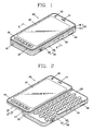
- FIGS. 1 and 2 are perspective views of a portable terminal according to the present invention, in which FIG. 1 shows a closed configuration of the portable terminal and FIG. 2 shows an open configuration of the portable terminal.
- the portable terminal 100 includes an upper body 110 and a lower body 120 coupled to each other so as to be movable with respect to each other.
- the portable terminal 100 shown in FIGS. 1 and 2 is open by a sliding motion in a width direction (horizontal direction).
- the portable terminal 100 may be configured to be open by a sliding motion in a length direction (vertical direction).
- a state that the upper body 110 overlaps the lower body 120 may be referred to as a 'closed configuration'.
- a state that the upper body 110 is moved in one direction thus to expose at least one part of the lower body 120 may be referred to as an 'open configuration.
- the upper body 110 and the lower body 120 perform a sliding motion with respect to a base 130.
- the present invention is not limited to this.
- one of the upper body 110 and the lower body 120 may be configured to swing or swivel with respect to the other.
- the portable terminal 100 functions in a standby mode when in the closed configuration, but the standby mode may be released by a user's manipulation.
- the portable terminal functions in a call mode, etc. when in the opened configuration.
- the call mode, etc. may be converted into a standby mode according to a user's manipulation or time lapse.
- Various components may be arranged on upper surfaces of the upper body 110 and the lower body 120 according to a function implemented by the portable terminal 100 with emphasis, or according to a type of a user interface.
- a display unit 113 may be disposed on an upper surface of the upper body 110, and a second manipulation portion 123 for inputting a control command may be disposed on an upper surface of the lower body 120.
- a case forming the appearance of the upper body 110 is formed by a front case 111 and a rear case 112.
- Each kind of electronic components are mounted in a space formed by the front case 111 and the rear case 112.
- one or more intermediate cases may be provided between the front case 111 and the rear case 112.
- the front and rear cases are usually formed by injection-molding synthetic resin, or formed with using metallic material such as stainless steel (STS) and titanium (Ti).
- On the front case 111 of the upper body 110 may be arranged a display unit 113, an audio output unit 114, a first image input unit 115, a first manipulation unit 116, and an audio input unit 117.
- the display unit 113 includes a display module for visually displaying information such as a liquid crystal displays (LCD) module, an organic light emitting diodes (OLED) module, and a transparent OLED (TOLED) module.
- a display module for visually displaying information such as a liquid crystal displays (LCD) module, an organic light emitting diodes (OLED) module, and a transparent OLED (TOLED) module.
- LCD liquid crystal displays
- OLED organic light emitting diodes
- TOLED transparent OLED
- the display unit 113 further comprises a touch screen to allow information to be inputted by a user's touch. Number keys that can be inputted in a touch manner may be outputted to the display unit 113.
- the display unit 113 may be formed to generated various tactile effects recognized by a user when being touched. This may be implemented by a haptic module interworking with the display unit 113. A representative tactile effect generated by the haptic module is vibration.
- the haptic module may be variously arranged according to a configuration aspect of not only the display unit 113 but also the portable terminal 100.
- the audio output unit 114 may be implemented in the form of a receiver or a speaker.
- the first image input unit 115 may be implemented as a camera module for capturing a still image or a moving image of a user, etc.
- the first manipulation unit 116 receives a command for controlling the operation of the portable terminal according to one embodiment of the present invention.
- the audio input unit 117 may be implemented in the form of a microphone, and may be arranged to be symmetric to the audio output unit 114 based on the display unit 113.
- the lower body 120 may include a front case 121 and a rear case 122.
- a second manipulation unit 123 (refer to FIG. 2 ) may be disposed on a front surface of the front case 121 of the lower body 120.
- a broadcast signal receiving antenna 132 as well as an antenna for calling may be disposed at one side of the lower body 120.
- the antenna 132 may be installed so as to be withdrawn from the lower body 120.
- the second manipulation unit 123 disposed on a front surface of the lower body 120 which overlaps the upper body 110 in a closed configuration (a state of FIG. 1 ) is exposed out from the upper body 110.
- Keys of the exposed second manipulation unit 123 may be configured to receive inputs relating to contents outputted to the display unit 113.
- the second manipulation unit 123 may include number keys or character keys, and the keys may be arranged in a QWERTY manner.
- icons of functional keys may be outputted to an exposed part of the touch screen so as to be inputted in a touching manner.
- the functional keys may be configured to receive commands for implementing functions such as 'temporal stop', 'play', 'forward', 'backward', and 'play list'.
- the second manipulation unit 123 was arranged on a front surface of the lower body 120.
- the present invention is not limited to this.
- an additional display unit interworking with the display unit 113 may be arranged on the front surface of the lower body 120.
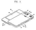
- FIG. 3 is a perspective view showing a rear surface of the portable terminal 100 of FIG. 2 .
- a third manipulation unit 124, an interface unit 126, etc. may be disposed on a side surface of the lower body 120.
- the first to third manipulation units 116, 123 and 124 may be referred to as user input units, and may be implemented in any types to input information in a user's tactile manner.
- the user input units may be implemented as a dome switch or a touch screen or a touch pad to input information or commands by a user's push or touch.
- the user input units may be implemented as a jog wheel or a jog switch.
- the first manipulation unit 116 may serve to input commands such as 'START', 'END', and 'SCOLL'
- the second manipulation unit 123 may serve to input numbers, characters, or symbols.
- the third manipulation unit 124 may be operated as a hot key for performing a particular function such as activation of the first image input unit 115.
- the interface unit 126 serves as a passage through which the portable terminal 100 of the present invention exchanges data with external devices.
- the interface unit 126 include wired/wireless terminals to be connected to earphones, power supplies to supply power to short-range communication ports (e.g., IrDA port, Bluetooth port, and wireless LAN port).
- the interface unit 126 may be implemented as a card socket (e.g., for coupling to a memory card, subscriber identity module (SIM) card, and user identity module (UIM) card).
- SIM subscriber identity module
- UIM user identity module
- a power supply unit 127 for supplying power to the portable terminal 100 is mounted to the lower body 120.
- the power supply unit 127 may be implemented as a rechargeable battery detachably coupled to the portable terminal for charging.
- a second image input unit 128 may be further mounted to the rear case 122 of the lower body 120.
- the second image input unit 128 may be a camera having an opposite capturing direction to the first image input unit 115 (refer to FIG. 1 ), and having different pixels from the first image input unit.
- the first image input unit 115 operates with a relatively lower resolution than the second image input unit 128.
- Such an arrangement works well during a video conference, for example.
- the relatively higher resolution of the image input unit 128 is useful for obtaining higher quality pictures for later use.
- a flash 129 and a mirror 130 are arranged near the second image input unit 128.
- the flash 129 provides light toward the object.
- the mirror 130 is useful for assisting a user to position the second image input unit 128 in a self-portrait mode.
- a second audio output unit 131 may be further arranged on the rear case 122.
- the second audio output unit 131 may implement a stereo function together with the first audio output unit 114 (refer to FIG. 1 ), and may be used for calling in a speaker phone mode.
- the second image input unit 128 was arranged on the rear case 122.
- the present invention is not limited to this.
- at least one of the components 128-131 explained to be arranged on the rear case 122 may be mounted on the rear case 112 of the upper body 110.
- the components arranged on the rear case 112 can be protected by the lower body 120 in a closed configuration.
- the first image input unit 115 may be configured to be rotatably formed to capture an object which can be captured by the second image input unit 128, even if the second image input unit 128 is not additionally provided.
- the upper body 110 and the lower body 120 are connected to each other by a slide module 360 (refer to FIG. 3 ).
- the slide module 360 serves to slide the upper body 110 with respect to the lower body 120 in closed and open configurations.
- the second manipulation unit 123 may have keys arranged with a larger size, or may have a larger number of keys.
- FIG. 4 is a disassembled perspective view of the portable terminal according to one embodiment of the present invention.
- a slide module 160 is provided between an upper body 110 and a lower body 120.
- the slide module 160 guides the upper body 110 to perform a sliding motion with respect to the lower body 120.
- the slide module 160 may include first and second slide members 170 and 180.
- the first slide member 170 is mounted to the rear case 112 of the upper body 110.
- the first slide member 170 may be formed of a metallic material such as Stainless Steel (SUS), and may be formed in the form of a plate or a sheet.
- SUS Stainless Steel
- the second slide member 180 is connected to the first slide member 170 so as to perform a relative sliding motion.
- the second slide member 180 may include guide rails 181a and 182b along which inserted two side surfaces of the first slide member 170 move.
- the second slide member 180 may be formed on one surface of the front case 121 which forms the appearance of the lower body 120. That is, the second slide member 180 is integrally fabricated with the lower body 120 to reduce the number of components and fabrication processes, thereby reducing the fabrication costs of the portable terminal.
- the present invention is not limited to this. That is, the second slide member 180 may be coupled to one surface of the lower body 120 as an additional component.
- An elastic module 165 may be provided between the first and second slide members 170 and 180.
- the elastic module 165 provides an elastic force so that the first and second slide members 170 and 180 can semi-automatically perform a relative sliding motion, i.e., so that the first and second slide members 170 and 180 having performed a relative sliding motion on a region more than a predetermined region can automatically perform a sliding motion after the region.
- the first slide member 170 may be provided with first and second guide holes 174 and 175.
- the first and second guide holes 174 and 175 may be implemented as through holes penetratingly formed at the first slide member 170, and may be configured in the form of slots extending in a sliding direction of the upper and lower bodies 110 and 120.
- the first slide member 170 may be further provided with a strength reinforcing unit 176 for covering the first and second guide holes 174 and 175.
- the strength reinforcing unit 176 is formed so that both ends thereof are protruding from a base plate 371, respectively, and a region between the two ends can cover the first and second guide holes 174 and 175. Under these configurations, peripheral strength of the first and second guide holes 174 and 175 may be reinforced.
- the second slide member 180 may include a base plate 184, and first and second slide rail units 181 and 182.
- the base plate 184 is formed on the front case 121 of the lower body 120, and a supporting plate 123a which supports the second manipulation unit 123 may be mounted on an upper surface of the base plate 184.
- the first and second slide rail units 181 and 182 are extending from one side of the base plate 184.
- the first slide rail unit 181 is slidably coupled to one side surface of the first slide member 171 and the first guide hole 174.
- Guide rails 181a and 181b slidably coupled to one side surface of the first slide member 171 and the first guide hole 174 may be formed at the first slide rail unit 181.
- the second slide rail unit 182 is slidably coupled to another side surface of the first slide member 171 and the second guide hole 175.
- Guide rails 182a and 182b slidably coupled to another side surface of the first slide member 171 and the second guide hole 175 may be formed at the second slide rail unit 182.
- the upper and lower bodies 110 and 120 are electrically connected to each other by a flexible printed circuit board (FPCB) 150.
- An FPCB retention unit 200 configured to transfer the FPCB 150 when the upper and lower bodies 110 and 120 perform a relative motion with respect to each other may be formed at the first slide member 170.
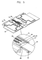
- FIG. 5 is a perspective view of a slide module, which shows a configuration of the FPCB retention unit 200.
- FIG. 5 shows the slide module in a closed configuration
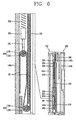
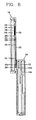
- FIG. 6 is a sectional view taken along line 'VI-VI' in FIG. 1 .
- first and second electronic components 141a and 141b are mounted in the upper and lower bodies 110 and 120, respectively.
- the electronic components indicate components which implement each kind of functions of the portable terminal, such as a display module, a circuit board, a camera and a printed circuit board.
- the first electronic component 141a may be a display module
- the second electronic component 141b may be a printed circuit board.
- the first and second electronic components 141a and 141b are electrically connected to each other by the FPCB 150. Accordingly, even if electronic components are mounted in the upper and lower bodies 110 and 120 separated from each other, the portable terminal may operate so that the electronic components can interwork with each other. For instance, information inputted to the second manipulation unit 123 may be displayed on the display unit 113.
- the FPCB 150 is configured to penetrate first and second openings 142a and 142b formed at the upper and lower bodies 110 and 120, respectively.
- the first and second openings 142a and 142b are formed so as to be near the ends of the upper and lower bodies 110 and 120 approaching to each other when the upper body 110 performs a sliding motion from a closed configuration to an open configuration. Referring to FIG. 6 , the first opening 142a and the second opening 142b are disposed in directions opposite to each other. The first and second openings 142a and 142b are formed at positions covered by the lower and upper bodies 120 and 110, respectively, so as not to be exposed to outside in closed and open configurations.
- the FPCB 150 is connected to the first electronic component 141 a. And, the FPCB 150 includes a first part 151 having a first bent portion 154 thereon, and a second part 152 extending from the first part 151 and connected to the second electronic component 141b.
- the first part 151 is connected to the first electronic component by passing through the first opening 142a, and is configured to have the first bent portion 154 thereon in an accommodation space 143 formed between the first slide member 170 and the upper body 110. Front and rear surfaces based on the first part 151 are arranged to be in parallel to a main surface of the upper body 110 (i.e., a surface where a display is arranged).
- the accommodation space 143 is formed between the first slide member 170 and the upper body 110.
- the accommodation space 143 may be formed in the upper body 110.
- the second part 152 is extending from the first part 151 thus to be connected to the second electronic component 141b.
- the second part 152 has a second bent portion 155 thereon thus to be extending up to the second opening 142b, and then is connected to the second electronic component 141b by passing through the second opening 142b.
- the second bent portion 155 is bent in an opposite direction to the first bent portion 154.
- the FPCB retention unit 200 moves the first bent portion 154 toward a moving direction of the upper body 110, thereby transmitting at least one part of the second part 152 into the accommodation space 143.
- the FPCB retention unit 200 may include a holder 220, another holder 210 and a spring 230.
- the other holder 210 is fixed to the first slide member 170, and is disposed in the accommodation space 143.
- the holder 220 is configured to perform a sliding motion in the accommodation space 143, and is connected to the first bent portion 154 of the FPCB 150.
- the holder 220 may be mounted on the first slide member 170 so as to be slidably moved.
- a guide unit 240 for guiding a slide motion of the holder 220 may be provided between the holder 220 and the first slide member 170.
- the guide unit 240 may include a sliding hanger 241 connected to the holder 200, and a rail 242 formed on the first slide member 170 and configured to guide movement of the sliding hanger 241 inserted thereinto.
- the sliding hanger 241 may be formed by bending a metallic pin or rod, and the rail 242 is protruding from the first slide member 170 thus to accommodate therein one side of the sliding hanger 241.
- a first bent portion 154 of the FPCB 150 may be connected to the rail 242.
- the rail 242 is implemented in the form of a guide rail having a predetermined length, and the sliding hanger 241 may be positioned at one end of the rail 242 in a closed configuration.
- a first rolling unit 250 roll-contacting the first bent portion 154 of the FPCB 150 may be additionally provided at the holder 220.
- the first rolling unit 250 is mounted to the sliding hanger 241.
- the first rolling unit 250 may include a first roller 251 rotatably mounted to the sliding hanger 241, and a first revolver 252 formed on an outer circumferential surface of the first roller 251 so as to roll-contact the first bent portion 154 of the FPCB 150.
- the first revolver 252 may be formed of an elastic material such as elastomer. The first rolling unit 250 serves to reduce friction applied to the surface of the FPCB 150 when the FPCB 150 is transferred.
- the spring 230 connects the other holder 210 and the holder 220 to each other, and provides an elastic force to move the holder 220 when the current state of the portable terminal is converted to an open configuration from a closed configuration.
- the spring 250 may be implemented in the form of a compression spring. In this case, the spring is arranged with a tensile state in a closed configuration as shown in FIG. 5 . The spring generates compressive force as the current state of the portable terminal is converted to an open configuration from a closed configuration. As a result, the sliding hanger 251 performs a sliding motion toward another end of the rail 252.
- a second rolling unit 260 roll-contacting the second bent portion 155 of the FPCB 150 may be further provided at the first slide member 170.
- the second rolling unit 260 may have a similar configuration to the first rolling unit 250. That is, the second rolling unit 260 may include a second roller 261 rotatably mounted to the first slide member 170, and a second revolver 262 formed on an outer circumferential surface of the second roller 261 so as to roll-contact the second bent portion 155 of the FPCB 150.
- FIG. 7 is a sectional view of the portable terminal, which shows an intermediate configuration between a closed configuration and an open configuration
- FIG. 8 is a sectional view of the portable terminal, which shows an open configuration.
- the upper body 110 performs a sliding motion with respect to the lower body 120 as shown in FIG. 7 .
- the spring 230 provides an elastic force to the holder 220 in the same direction as a moving direction of the upper body 110.
- the elastic force of the spring 230 the first bent portion 154 of the FPCB 150 is moved toward a moving direction of the upper body 110.
- a part of the second part 152 of the FPCB 150 is transferred to the accommodation space 143.
- the first and second rolling units 250 and 260 allow the FPCB 150 to be smoothly transferred, and prevent excessive friction from occurring from the first and second bent portions 154 and 155.
- the first bent portion 154 of the FPCB 150 continuously moves to be positioned at the end of the accommodation space 143. Furthermore, most parts of the second part 152 of the FPCB 150 move into the accommodation space 143.
- the holder 220 moves to the original position according to reverse orders to the aforementioned orders, and the second part 252 of the FPCB 150 is transferred to outside of the accommodation space 143.
- the mobility of the first bent portion 154 of the FPCB enables a long distance between the first and second openings 142a and 142b.
- the distance between the first and second openings 142a and 142b becomes far from each other, at least one of the first and second openings 142a and 142b may not be exposed to outside, even if a relative sliding distance of the upper and lower bodies 110 and 120 in an open configuration, i.e., a stroke is increased.
- This may increase a relative sliding range of the upper and lower bodies 110 and 120, i.e., a stroke of the upper and lower bodies 110 and 120, without exposing at least one of the first and second openings 142a and 142b to outside.
- the accommodation space 143 configured to accommodate the FPCB 150 therein is formed between the upper body 110 and the slide module 160.
- the slide module 160 is not an absolutely necessary component in the present invention.
- the upper and lower bodies 110 and 120 may be directly connected to each other without the slide module 160.
- the accommodation space 143 is formed in the upper body 110, and the FPCB retention unit 200 is also mounted in the upper body 110.
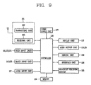
- FIG. 9 is a block diagram of the portable terminal 100 according to one embodiment of the present invention.
- the portable terminal 100 may comprise a wireless communication module 191, user input units 116, 123 and 124, image input units 115 and 128, an audio input unit 117, a display unit 113, audio output units 114 and 131, a sensing unit 196, an interface unit 126, a broadcast receiving module 195, a memory 194, a power supply unit 127, and a controller 190.
- a wireless communication module 191 user input units 116, 123 and 124, image input units 115 and 128, an audio input unit 117, a display unit 113, audio output units 114 and 131, a sensing unit 196, an interface unit 126, a broadcast receiving module 195, a memory 194, a power supply unit 127, and a controller 190.
- the controller 190 typically controls the overall operations of the portable terminal 100. For example, the controller 190 performs controlling and processing associated with voice calls, data communications, video calls, and the like. In addition, the controller 190 controls functions of the portable terminal 100 relating to the present invention, as well as general functions.
- the communication module 191 transmits/receives wireless signals to/from a base station through an antenna. For instance, the wireless communication module 191 transmits/receives voice data, text data, image data, and control data under control of the controller 190.
- the wireless communication module 191 includes a transmitting unit 192 for transmitting signals after a modulation process, and a receiving unit 192 for demodulating received signals.
- the user input units 116, 123 and 124 shown in FIG. 1 provide, to the controller 190, key input data input by a user so as to control the operation of the portable terminal 100.
- the image input units 115 and 128 process image frames such as still images or moving images captured by an image sensor in a video-call mode or a capturing mode. Then, the processed image frames are converted to image data that can be displayed on the display unit 113, thereby being output to the display unit 113. Image frames processed by the first and second image input units 115 and 128 are stored in the memory 194 under control of the controller 190, or are transmitted to outside through the wireless communication module 191.
- the audio input unit 117 receives an external audio signal through a microphone in a call mode, or a recording mode, or a voice recognition mode, and the like, and then processes the received signal into electric voice data.
- the processed voice data is converted into data that can be transmitted to the base station through the wireless communication module 191, and then is output to the wireless communication module 191.
- the processed voice data is output so as to be stored in the memory 194.
- the audio input unit 117 may include assorted noise removing algorithms to remove noise generated in the course of receiving the external audio signal.
- the display unit 113 may output information processed in the portable terminal. For example, when the portable terminal 100 operates in a phone call mode, the display unit 113 will provide a User Interface (UI) or a Graphic User Interface (GUI) which includes information associated with the call. As another example, if the portable terminal 100 is in a video call mode or a capturing mode, the display unit 113 may display captured images, or UI or GUI under control of the controller 190. When the display unit 113 includes a touch screen, it may be used as an input device as well as an output device.
- UI User Interface
- GUI Graphic User Interface
- the audio output units 114 and 131 convert audio data received from the wireless communication module 191, or audio data stored in the memory 194, under control of the controller 190. Then, the audio output units 114 and 131 output the converted data to outside.
- the audio output units 114 and 131 output audio signals relating to functions performed in the portable terminal 100, such as sound indicating a call signal reception, or sound indicating a message reception.
- These audio output units 114 and 131 include a speaker, a receiver, a buzzer, etc.
- the sensing unit 196 senses a current status of the portable terminal 100 such as an open/close status of the portable terminal, a position of the portable terminal 100, or whether a user has contacted the portable terminal 100, thereby generating sensing signals to control the operation of the portable terminal 100. For instance, if the portable terminal 100 is a slide phone, the sensing unit 196 senses whether the slide phone has been open or not, and outputs the sensing result to the controller 190, thereby controlling the operation of the portable terminal 100. Furthermore, the sensing unit 196 performs sensing functions relating to whether power has been supplied from the power supply unit 127, or whether the interface unit 126 has been coupled to an external device, and the like.
- the interface unit 126 interfaces a wire/wireless headset, an external charger, a wire/wireless data port, a card socket (e.g., memory card, SIM/UIM card), and the like, with any types of external devices connected to the portable terminal 100.
- the interface unit 126 transmits data or power received from external devices, to each component in the portable terminal, or transmits data in the portable terminal 100 to the external devices.
- the memory 194 may store programs to be processed and controlled by the controller 190, or may temporarily store input/output data (e.g., phonebook, messages, still images, moving images, etc.).
- the memory 194 may store programs to control the operation of the portable terminal 100 according to the present invention.
- the memory 194 may be implemented using any type of suitable storage medium including a flash memory type, a hard disk type, a multimedia card micro type, a memory card type (e.g., SD or DX memory), Random Access Memory (RAM), Read-Only Memory (ROM), and the like.
- the broadcast receiving module 195 receives broadcasting signals transmitted through satellite or terrestrial wave, and then converts them to broadcasting data that can be output to the audio output units 114 and 131 and the display unit 113, thereby outputting the broadcasting data to the controller 190.
- the broadcast receiving module 195 receives broadcasting-related additional data (e.g., Electric Program Guide: EPG, channel list, and the like). Broadcasting data and additional data converted by the broadcast receiving module 195 may be stored in the memory 194.
- the power supply unit 127 receives inner or outer power, and supplies the power to each component of the portable terminal under control of the controller 190.
- the FPCB between the upper and lower bodies is drawn into the upper body. This may prevent the FPCB from being exposed to outside, and may enhance the appearance.
Abstract
Description
- The present invention relates to a portable terminal, and particularly, to a portable terminal configured to be open and closed in a sliding manner.
- A portable terminal is a device that can be carried around and has one or more functions such as voice and video call communication, inputting and outputting information, storing data, and the like.
- As such functions become more diversified, the portable terminal can support more complicated functions such as capturing images or video, reproducing music or video files, playing games, receiving broadcast signals, and the like. By comprehensively and collectively implementing such functions, the portable terminal may be embodied in the form of a multimedia player or device.
- In order to implement various functions of such multimedia players or devices, the multimedia player requires sufficient support in terms of hardware or software, for which numerous attempts are being made and implemented. For example, a user interface allowing users to easily and conveniently search for and select one or more functions is provided.
- As the portable terminal is considered as a personal belonging, form factors are variously implemented so that selections according to each personality can be facilitated. The portable terminal has various types such as a bar type in which an input unit, an output unit, and a display unit are disposed on one body, a folder type in which one body is rotated to be open or closed with respect to another body, a swing type, and a slide type in which one body is performs a sliding motion with respect to another body thus to be open or closed.
- Among these various types, the slide type is being spotlighted due to a simple opening operation, and a characteristic that a display unit is easily recognized by being always exposed to outside of the portable terminal. However, when increasing a sliding distance (stroke) in the slide type portable terminal, a flexible printed circuit board (FPCB), a means for electrically connecting two bodies to each other may be exposed to outside.
-
US 2003/0081375 A1 describes a portable information terminal comprising an operating unit and a main unit. The operating unit is configured in such a manner as to freely slide with respect to the main unit. The operating unit and the main unit are electrically and mechanically connected by a resilient cable member having a spiral winding. The resilient cable member having the spiral winding includes an FPC stuck to either one surface or both surfaces of the resilient cable member. - Therefore, an object of the present invention is to provide a portable terminal capable of utilizing a wide user interface region by opening and closing one body in a sliding manner with respect to another body, capable of preventing a flexible printed circuit board (FPCB) from being exposed to outside when implementing a long stroke, and capable of having an enhanced appearance.
- This object is solved by the features of the independent claim.
- There is provided a portable terminal, preferably comprising: a lower body; an upper body disposed to overlap the lower body, and formed to be in an open configuration which exposes a part of an upper surface of the lower body, and a closed configuration which covers the one part by a sliding motion; a flexible printed circuit board (FPCB) having one end connected to the lower body and another end connected to the upper body, and formed to be bent as the upper body moves with respect to the lower body; and an FPCB retention unit configured to elastically move one or more bent portions of the FPCB into an accommodation space formed in the upper body when the upper body moves from a closed configuration to an open configuration.
- The FPCB retention unit may include a first holder fixed to an inner side of the upper body; a second holder movably mounted to the accommodation space of the upper body, and configured to pull the bent portion; and a spring supported between the first and second holders, and configured to restore the second holder to a direction approaching to the first holder when the closed configuration is converted into the open configuration.
- The portable terminal may further comprise a guide unit configured to guide the second holder to linearly move with pulling the bent portion.
- The guide unit may include a rail formed along a moving direction of the second holder; and a sliding hanger having one end connected to the second holder, and another end which allows the FPCB to be hung, and configured to perform a sliding motion along the rail.
- The sliding hanger may be formed by bending a pin or a rod formed of metallic material. In this case, the rail may be formed in one pair, and both ends of the sliding rail may be configured to move with contacting the one pair of rails.
- The sliding hanger may further comprise a first rolling unit configured to roll-contact the bent portion.
- The first rolling unit may include a first roller rotatably mounted to the sliding hanger, and a first revolver formed on an outer circumferential surface of the first roller so as to roll-contact the bent portion of the FPCB. The first revolver may be formed of elastomer which can be elastically transformed. And, the spring may be implemented as a tensile coil spring.
- The FPCB may further include a reverse bent portion bent in an opposite direction to the bent portion, and the reverse bent portion may be configured to contact a second rolling unit rotated by being fixed to the upper body.
- The portable terminal may further comprise a slide module configured to elastically guide the upper body when the upper body moves to an open or closed configuration.
- The slide module may include a first slide member fixed to the lower body; a second slide member fixed to the upper body, and formed at the first slide member so as to perform a sliding motion; and an elastic module disposed between the first and second slide members, and configured to store an elastic force therein while the second slide member performs a sliding motion by a predetermined distance, and to move the second slide member with using the stored elastic energy when the second slide member moves by a distance more than the predetermined distance.
- The upper body may be configured to perform a sliding motion in a width direction. And, a 'qwerty' type of key pad may be installed at the lower body.
- The foregoing and other objects, features, aspects and advantages of the present invention will become more apparent from the following detailed description of the present invention when taken in conjunction with the accompanying drawings.
- The accompanying drawings, which are included to provide a further understanding of the invention and are incorporated in and constitute a part of this specification, illustrate embodiments of the invention and together with the description serve to explain the principles of the invention.
- In the drawings:
-
FIG. 1 is a perspective view showing a closed configuration of a portable terminal according to one embodiment of the present invention; -
FIG. 2 is a perspective view showing an open configuration of the portable terminal ofFIG. 1 ; -
FIG. 3 is a perspective view showing a rear surface of the portable terminal ofFIG. 2 ; -
FIG. 4 is a disassembled perspective vie of the portable terminal according to one embodiment of the present invention; -
FIG. 5 is a perspective view of a slide module ofFIG. 4 ; -
FIG. 6 is a sectional view taken along line 'VI-VI' inFIG. 1 ; -
FIG. 7 is a sectional view of the portable terminal, which shows an intermediate configuration between a closed configuration and an open configuration; -
FIG. 8 is a sectional view of the portable terminal, which shows an open configuration; and -
FIG. 9 is a block diagram of the portable terminal according to the present invention. - Description will now be given in detail of the present invention, with reference to the accompanying drawings.
- For the sake of brief description with reference to the drawings, the same or equivalent components will be provided with the same reference numbers, and description thereof will not be repeated.
- The portable terminal according to exemplary embodiments of the present invention will now be described with reference to the accompanying drawings. In the following description, usage of suffixes such as 'module', 'part' or 'unit' used for referring to elements is given merely to facilitate explanation of the present invention, without having any significant meaning by itself.
- Hereinafter, a portable terminal according to the present invention will be explained in more detail with reference to the attached drawings. The same configurations as those of the aforementioned embodiment will be provided with the same reference numerals, and their detailed explanations will be omitted.
-
FIGS. 1 and 2 are perspective views of a portable terminal according to the present invention, in whichFIG. 1 shows a closed configuration of the portable terminal andFIG. 2 shows an open configuration of the portable terminal. - As shown in
FIGS. 1 and 2 , theportable terminal 100 includes anupper body 110 and alower body 120 coupled to each other so as to be movable with respect to each other. Theportable terminal 100 shown inFIGS. 1 and 2 is open by a sliding motion in a width direction (horizontal direction). However, theportable terminal 100 may be configured to be open by a sliding motion in a length direction (vertical direction). - As shown in
FIG. 1 , a state that theupper body 110 overlaps thelower body 120 may be referred to as a 'closed configuration'. As shown inFIG. 2 , a state that theupper body 110 is moved in one direction thus to expose at least one part of thelower body 120 may be referred to as an 'open configuration. In the preferred embodiment, theupper body 110 and thelower body 120 perform a sliding motion with respect to abase 130. However, the present invention is not limited to this. For instance, one of theupper body 110 and thelower body 120 may be configured to swing or swivel with respect to the other. - Typically, the
portable terminal 100 functions in a standby mode when in the closed configuration, but the standby mode may be released by a user's manipulation. Also, the portable terminal functions in a call mode, etc. when in the opened configuration. Here, the call mode, etc. may be converted into a standby mode according to a user's manipulation or time lapse. - Various components may be arranged on upper surfaces of the
upper body 110 and thelower body 120 according to a function implemented by theportable terminal 100 with emphasis, or according to a type of a user interface. For instance, as shown inFIG. 2 , adisplay unit 113 may be disposed on an upper surface of theupper body 110, and asecond manipulation portion 123 for inputting a control command may be disposed on an upper surface of thelower body 120. - Referring to
FIG. 1 , a case forming the appearance of the upper body 110 (casing, housing cover, etc.) is formed by afront case 111 and arear case 112. Each kind of electronic components are mounted in a space formed by thefront case 111 and therear case 112. If desired, one or more intermediate cases may be provided between thefront case 111 and therear case 112. The front and rear cases are usually formed by injection-molding synthetic resin, or formed with using metallic material such as stainless steel (STS) and titanium (Ti). - On the
front case 111 of theupper body 110, may be arranged adisplay unit 113, anaudio output unit 114, a firstimage input unit 115, afirst manipulation unit 116, and anaudio input unit 117. - The
display unit 113 includes a display module for visually displaying information such as a liquid crystal displays (LCD) module, an organic light emitting diodes (OLED) module, and a transparent OLED (TOLED) module. - The
display unit 113 further comprises a touch screen to allow information to be inputted by a user's touch. Number keys that can be inputted in a touch manner may be outputted to thedisplay unit 113. - The
display unit 113 may be formed to generated various tactile effects recognized by a user when being touched. This may be implemented by a haptic module interworking with thedisplay unit 113. A representative tactile effect generated by the haptic module is vibration. The haptic module may be variously arranged according to a configuration aspect of not only thedisplay unit 113 but also theportable terminal 100. - The
audio output unit 114 may be implemented in the form of a receiver or a speaker. The firstimage input unit 115 may be implemented as a camera module for capturing a still image or a moving image of a user, etc. Thefirst manipulation unit 116 receives a command for controlling the operation of the portable terminal according to one embodiment of the present invention. Theaudio input unit 117 may be implemented in the form of a microphone, and may be arranged to be symmetric to theaudio output unit 114 based on thedisplay unit 113. - Like the
upper body 110, thelower body 120 may include afront case 121 and arear case 122. A second manipulation unit 123 (refer toFIG. 2 ) may be disposed on a front surface of thefront case 121 of thelower body 120. - A broadcast
signal receiving antenna 132 as well as an antenna for calling may be disposed at one side of thelower body 120. Theantenna 132 may be installed so as to be withdrawn from thelower body 120. - Referring to
FIG. 2 , once theupper body 110 performs a sliding motion with respect to thelower body 120, thesecond manipulation unit 123 disposed on a front surface of thelower body 120 which overlaps theupper body 110 in a closed configuration (a state ofFIG. 1 ) is exposed out from theupper body 110. - Keys of the exposed
second manipulation unit 123 may be configured to receive inputs relating to contents outputted to thedisplay unit 113. Thesecond manipulation unit 123 may include number keys or character keys, and the keys may be arranged in a QWERTY manner. - If the
second manipulation unit 123 is a touch screen, icons of functional keys may be outputted to an exposed part of the touch screen so as to be inputted in a touching manner. For instance, in case of outputting a moving image to thedisplay unit 113, the functional keys may be configured to receive commands for implementing functions such as 'temporal stop', 'play', 'forward', 'backward', and 'play list'. - In the aforementioned embodiment, the
second manipulation unit 123 was arranged on a front surface of thelower body 120. However, the present invention is not limited to this. For instance, an additional display unit interworking with thedisplay unit 113 may be arranged on the front surface of thelower body 120. -
FIG. 3 is a perspective view showing a rear surface of theportable terminal 100 ofFIG. 2 . - Referring to
FIG. 3 , athird manipulation unit 124, aninterface unit 126, etc. may be disposed on a side surface of thelower body 120. - The first to
third manipulation units - For instance, the user input units may be implemented as a dome switch or a touch screen or a touch pad to input information or commands by a user's push or touch. Also, the user input units may be implemented as a jog wheel or a jog switch.
- In a functional aspect, the
first manipulation unit 116 may serve to input commands such as 'START', 'END', and 'SCOLL', and thesecond manipulation unit 123 may serve to input numbers, characters, or symbols. And, thethird manipulation unit 124 may be operated as a hot key for performing a particular function such as activation of the firstimage input unit 115. - The
interface unit 126 serves as a passage through which theportable terminal 100 of the present invention exchanges data with external devices. For instance, theinterface unit 126 include wired/wireless terminals to be connected to earphones, power supplies to supply power to short-range communication ports (e.g., IrDA port, Bluetooth port, and wireless LAN port). - Also, the
interface unit 126 may be implemented as a card socket (e.g., for coupling to a memory card, subscriber identity module (SIM) card, and user identity module (UIM) card). - A
power supply unit 127 for supplying power to theportable terminal 100 is mounted to thelower body 120. Thepower supply unit 127 may be implemented as a rechargeable battery detachably coupled to the portable terminal for charging. - A second
image input unit 128 may be further mounted to therear case 122 of thelower body 120. The secondimage input unit 128 may be a camera having an opposite capturing direction to the first image input unit 115 (refer toFIG. 1 ), and having different pixels from the first image input unit. - For instance, the first
image input unit 115 operates with a relatively lower resolution than the secondimage input unit 128. Such an arrangement works well during a video conference, for example. The relatively higher resolution of theimage input unit 128 is useful for obtaining higher quality pictures for later use. - A
flash 129 and amirror 130 are arranged near the secondimage input unit 128. When capturing an object by the secondimage input unit 128, theflash 129 provides light toward the object. Themirror 130 is useful for assisting a user to position the secondimage input unit 128 in a self-portrait mode. - A second
audio output unit 131 may be further arranged on therear case 122. - The second
audio output unit 131 may implement a stereo function together with the first audio output unit 114 (refer toFIG. 1 ), and may be used for calling in a speaker phone mode. - In the above embodiment, the second
image input unit 128 was arranged on therear case 122. However, the present invention is not limited to this. For instance, at least one of the components 128-131 explained to be arranged on therear case 122 may be mounted on therear case 112 of theupper body 110. In this case, the components arranged on therear case 112 can be protected by thelower body 120 in a closed configuration. Also, the firstimage input unit 115 may be configured to be rotatably formed to capture an object which can be captured by the secondimage input unit 128, even if the secondimage input unit 128 is not additionally provided. - In order to slide the
lower body 120 when theupper body 110 performs a sliding motion, theupper body 110 and thelower body 120 are connected to each other by a slide module 360 (refer toFIG. 3 ). The slide module 360 serves to slide theupper body 110 with respect to thelower body 120 in closed and open configurations. - If the
upper body 110 is much slid, a front surface of thelower body 120 has a larger exposed area. As the exposed area becomes larger, thesecond manipulation unit 123 may have keys arranged with a larger size, or may have a larger number of keys. -
FIG. 4 is a disassembled perspective view of the portable terminal according to one embodiment of the present invention. - A
slide module 160 is provided between anupper body 110 and alower body 120. Theslide module 160 guides theupper body 110 to perform a sliding motion with respect to thelower body 120. - The
slide module 160 may include first andsecond slide members - Referring to
FIG. 4 , thefirst slide member 170 is mounted to therear case 112 of theupper body 110. Thefirst slide member 170 may be formed of a metallic material such as Stainless Steel (SUS), and may be formed in the form of a plate or a sheet. - The
second slide member 180 is connected to thefirst slide member 170 so as to perform a relative sliding motion. Thesecond slide member 180 may includeguide rails first slide member 170 move. - The
second slide member 180 may be formed on one surface of thefront case 121 which forms the appearance of thelower body 120. That is, thesecond slide member 180 is integrally fabricated with thelower body 120 to reduce the number of components and fabrication processes, thereby reducing the fabrication costs of the portable terminal. However, the present invention is not limited to this. That is, thesecond slide member 180 may be coupled to one surface of thelower body 120 as an additional component. - An
elastic module 165 may be provided between the first andsecond slide members elastic module 165 provides an elastic force so that the first andsecond slide members second slide members - The
first slide member 170 may be provided with first and second guide holes 174 and 175. The first and second guide holes 174 and 175 may be implemented as through holes penetratingly formed at thefirst slide member 170, and may be configured in the form of slots extending in a sliding direction of the upper andlower bodies - The
first slide member 170 may be further provided with astrength reinforcing unit 176 for covering the first and second guide holes 174 and 175. Thestrength reinforcing unit 176 is formed so that both ends thereof are protruding from a base plate 371, respectively, and a region between the two ends can cover the first and second guide holes 174 and 175. Under these configurations, peripheral strength of the first and second guide holes 174 and 175 may be reinforced. - The
second slide member 180 may include abase plate 184, and first and secondslide rail units - The
base plate 184 is formed on thefront case 121 of thelower body 120, and a supportingplate 123a which supports thesecond manipulation unit 123 may be mounted on an upper surface of thebase plate 184. The first and secondslide rail units base plate 184. - The first
slide rail unit 181 is slidably coupled to one side surface of the first slide member 171 and thefirst guide hole 174.Guide rails first guide hole 174 may be formed at the firstslide rail unit 181. - The second
slide rail unit 182 is slidably coupled to another side surface of the first slide member 171 and thesecond guide hole 175.Guide rails second guide hole 175 may be formed at the secondslide rail unit 182. - The upper and
lower bodies FPCB retention unit 200 configured to transfer theFPCB 150 when the upper andlower bodies first slide member 170. - Hereinafter, a detailed structure of the
FPCB retention unit 200 will be explained. -
FIG. 5 is a perspective view of a slide module, which shows a configuration of theFPCB retention unit 200.FIG. 5 shows the slide module in a closed configuration, andFIG. 6 is a sectional view taken along line 'VI-VI' inFIG. 1 . - Referring to
FIG. 6 , first and secondelectronic components lower bodies FIG. 6 , the firstelectronic component 141a may be a display module, and the secondelectronic component 141b may be a printed circuit board. - The first and second
electronic components FPCB 150. Accordingly, even if electronic components are mounted in the upper andlower bodies second manipulation unit 123 may be displayed on thedisplay unit 113. - The
FPCB 150 is configured to penetrate first andsecond openings lower bodies - The first and
second openings lower bodies upper body 110 performs a sliding motion from a closed configuration to an open configuration. Referring toFIG. 6 , thefirst opening 142a and thesecond opening 142b are disposed in directions opposite to each other. The first andsecond openings upper bodies - The
FPCB 150 is connected to the firstelectronic component 141 a. And, theFPCB 150 includes afirst part 151 having a firstbent portion 154 thereon, and asecond part 152 extending from thefirst part 151 and connected to the secondelectronic component 141b. - The
first part 151 is connected to the first electronic component by passing through thefirst opening 142a, and is configured to have the firstbent portion 154 thereon in anaccommodation space 143 formed between thefirst slide member 170 and theupper body 110. Front and rear surfaces based on thefirst part 151 are arranged to be in parallel to a main surface of the upper body 110 (i.e., a surface where a display is arranged). - In the preferred embodiment, the
accommodation space 143 is formed between thefirst slide member 170 and theupper body 110. However, theaccommodation space 143 may be formed in theupper body 110. - The
second part 152 is extending from thefirst part 151 thus to be connected to the secondelectronic component 141b. Thesecond part 152 has a second bent portion 155 thereon thus to be extending up to thesecond opening 142b, and then is connected to the secondelectronic component 141b by passing through thesecond opening 142b. Here, the second bent portion 155 is bent in an opposite direction to the firstbent portion 154. - When the
upper body 110 is moved to an open configuration from a closed configuration, theFPCB retention unit 200 moves the firstbent portion 154 toward a moving direction of theupper body 110, thereby transmitting at least one part of thesecond part 152 into theaccommodation space 143. - Referring to
FIGS. 5 and6 , theFPCB retention unit 200 may include aholder 220, anotherholder 210 and aspring 230. - The
other holder 210 is fixed to thefirst slide member 170, and is disposed in theaccommodation space 143. - The
holder 220 is configured to perform a sliding motion in theaccommodation space 143, and is connected to the firstbent portion 154 of theFPCB 150. - The
holder 220 may be mounted on thefirst slide member 170 so as to be slidably moved. For this, a guide unit 240 for guiding a slide motion of theholder 220 may be provided between theholder 220 and thefirst slide member 170. - The guide unit 240 may include a sliding
hanger 241 connected to theholder 200, and a rail 242 formed on thefirst slide member 170 and configured to guide movement of the slidinghanger 241 inserted thereinto. - The sliding
hanger 241 may be formed by bending a metallic pin or rod, and the rail 242 is protruding from thefirst slide member 170 thus to accommodate therein one side of the slidinghanger 241. A firstbent portion 154 of theFPCB 150 may be connected to the rail 242. - The rail 242 is implemented in the form of a guide rail having a predetermined length, and the sliding
hanger 241 may be positioned at one end of the rail 242 in a closed configuration. - A
first rolling unit 250 roll-contacting the firstbent portion 154 of theFPCB 150 may be additionally provided at theholder 220. In the preferred embodiment, thefirst rolling unit 250 is mounted to the slidinghanger 241. - The
first rolling unit 250 may include afirst roller 251 rotatably mounted to the slidinghanger 241, and afirst revolver 252 formed on an outer circumferential surface of thefirst roller 251 so as to roll-contact the firstbent portion 154 of theFPCB 150. Thefirst revolver 252 may be formed of an elastic material such as elastomer. Thefirst rolling unit 250 serves to reduce friction applied to the surface of theFPCB 150 when theFPCB 150 is transferred. - The
spring 230 connects theother holder 210 and theholder 220 to each other, and provides an elastic force to move theholder 220 when the current state of the portable terminal is converted to an open configuration from a closed configuration. Thespring 250 may be implemented in the form of a compression spring. In this case, the spring is arranged with a tensile state in a closed configuration as shown inFIG. 5 . The spring generates compressive force as the current state of the portable terminal is converted to an open configuration from a closed configuration. As a result, the slidinghanger 251 performs a sliding motion toward another end of therail 252. - A
second rolling unit 260 roll-contacting the second bent portion 155 of theFPCB 150 may be further provided at thefirst slide member 170. Thesecond rolling unit 260 may have a similar configuration to thefirst rolling unit 250. That is, thesecond rolling unit 260 may include asecond roller 261 rotatably mounted to thefirst slide member 170, and asecond revolver 262 formed on an outer circumferential surface of thesecond roller 261 so as to roll-contact the second bent portion 155 of theFPCB 150. - Hereinafter, the operation of the FPCB retention unit will be explained with reference to
FIGS. 7 and8 . -
FIG. 7 is a sectional view of the portable terminal, which shows an intermediate configuration between a closed configuration and an open configuration, andFIG. 8 is a sectional view of the portable terminal, which shows an open configuration. - Hereinafter, a relative motion of the
upper body 110 with respect to thelower body 120 will be explained. - Once a user pushes the
upper body 110 in a closed configuration, theupper body 110 performs a sliding motion with respect to thelower body 120 as shown inFIG. 7 . - Here, the
spring 230 provides an elastic force to theholder 220 in the same direction as a moving direction of theupper body 110. By the elastic force of thespring 230, the firstbent portion 154 of theFPCB 150 is moved toward a moving direction of theupper body 110. As a result, a part of thesecond part 152 of theFPCB 150 is transferred to theaccommodation space 143. - During this process, the first and second rolling
units FPCB 150 to be smoothly transferred, and prevent excessive friction from occurring from the first and secondbent portions 154 and 155. - If the current configuration of the portable terminal is converted into an open configuration from a closed configuration as shown in
FIG. 8 , the firstbent portion 154 of theFPCB 150 continuously moves to be positioned at the end of theaccommodation space 143. Furthermore, most parts of thesecond part 152 of theFPCB 150 move into theaccommodation space 143. - If the current configuration of the portable terminal is converted into a closed configuration from an open configuration, the
holder 220 moves to the original position according to reverse orders to the aforementioned orders, and thesecond part 252 of theFPCB 150 is transferred to outside of theaccommodation space 143. - The mobility of the first
bent portion 154 of the FPCB enables a long distance between the first andsecond openings second openings second openings lower bodies lower bodies lower bodies second openings - In the aforementioned embodiment, the
accommodation space 143 configured to accommodate theFPCB 150 therein is formed between theupper body 110 and theslide module 160. However, theslide module 160 is not an absolutely necessary component in the present invention. The upper andlower bodies slide module 160. In this case, theaccommodation space 143 is formed in theupper body 110, and theFPCB retention unit 200 is also mounted in theupper body 110. -
FIG. 9 is a block diagram of theportable terminal 100 according to one embodiment of the present invention. - Referring to
FIG. 9 , theportable terminal 100 according to one embodiment of the present invention may comprise awireless communication module 191,user input units image input units audio input unit 117, adisplay unit 113,audio output units sensing unit 196, aninterface unit 126, abroadcast receiving module 195, amemory 194, apower supply unit 127, and acontroller 190. - The
controller 190 typically controls the overall operations of theportable terminal 100. For example, thecontroller 190 performs controlling and processing associated with voice calls, data communications, video calls, and the like. In addition, thecontroller 190 controls functions of theportable terminal 100 relating to the present invention, as well as general functions. - The
communication module 191 transmits/receives wireless signals to/from a base station through an antenna. For instance, thewireless communication module 191 transmits/receives voice data, text data, image data, and control data under control of thecontroller 190. Thewireless communication module 191 includes a transmittingunit 192 for transmitting signals after a modulation process, and a receivingunit 192 for demodulating received signals. - The
user input units FIG. 1 provide, to thecontroller 190, key input data input by a user so as to control the operation of theportable terminal 100. - The
image input units display unit 113, thereby being output to thedisplay unit 113. Image frames processed by the first and secondimage input units memory 194 under control of thecontroller 190, or are transmitted to outside through thewireless communication module 191. - The
audio input unit 117 receives an external audio signal through a microphone in a call mode, or a recording mode, or a voice recognition mode, and the like, and then processes the received signal into electric voice data. In the case of a call mode, the processed voice data is converted into data that can be transmitted to the base station through thewireless communication module 191, and then is output to thewireless communication module 191. In the case of a recording mode, the processed voice data is output so as to be stored in thememory 194. - The
audio input unit 117 may include assorted noise removing algorithms to remove noise generated in the course of receiving the external audio signal. - The
display unit 113 may output information processed in the portable terminal. For example, when theportable terminal 100 operates in a phone call mode, thedisplay unit 113 will provide a User Interface (UI) or a Graphic User Interface (GUI) which includes information associated with the call. As another example, if theportable terminal 100 is in a video call mode or a capturing mode, thedisplay unit 113 may display captured images, or UI or GUI under control of thecontroller 190. When thedisplay unit 113 includes a touch screen, it may be used as an input device as well as an output device. - In a call mode or a recording mode, a voice recognition mode, a broadcasting signal reception mode, and the like, the
audio output units wireless communication module 191, or audio data stored in thememory 194, under control of thecontroller 190. Then, theaudio output units - The
audio output units portable terminal 100, such as sound indicating a call signal reception, or sound indicating a message reception. Theseaudio output units - The
sensing unit 196 senses a current status of theportable terminal 100 such as an open/close status of the portable terminal, a position of theportable terminal 100, or whether a user has contacted theportable terminal 100, thereby generating sensing signals to control the operation of theportable terminal 100. For instance, if theportable terminal 100 is a slide phone, thesensing unit 196 senses whether the slide phone has been open or not, and outputs the sensing result to thecontroller 190, thereby controlling the operation of theportable terminal 100. Furthermore, thesensing unit 196 performs sensing functions relating to whether power has been supplied from thepower supply unit 127, or whether theinterface unit 126 has been coupled to an external device, and the like. - The
interface unit 126 interfaces a wire/wireless headset, an external charger, a wire/wireless data port, a card socket (e.g., memory card, SIM/UIM card), and the like, with any types of external devices connected to theportable terminal 100. Theinterface unit 126 transmits data or power received from external devices, to each component in the portable terminal, or transmits data in theportable terminal 100 to the external devices. - The
memory 194 may store programs to be processed and controlled by thecontroller 190, or may temporarily store input/output data (e.g., phonebook, messages, still images, moving images, etc.). Thememory 194 may store programs to control the operation of theportable terminal 100 according to the present invention. Thememory 194 may be implemented using any type of suitable storage medium including a flash memory type, a hard disk type, a multimedia card micro type, a memory card type (e.g., SD or DX memory), Random Access Memory (RAM), Read-Only Memory (ROM), and the like. - The
broadcast receiving module 195 receives broadcasting signals transmitted through satellite or terrestrial wave, and then converts them to broadcasting data that can be output to theaudio output units display unit 113, thereby outputting the broadcasting data to thecontroller 190. Thebroadcast receiving module 195 receives broadcasting-related additional data (e.g., Electric Program Guide: EPG, channel list, and the like). Broadcasting data and additional data converted by thebroadcast receiving module 195 may be stored in thememory 194. - The
power supply unit 127 receives inner or outer power, and supplies the power to each component of the portable terminal under control of thecontroller 190. - According to the present invention, when the upper body is in an open configuration, the FPCB between the upper and lower bodies is drawn into the upper body. This may prevent the FPCB from being exposed to outside, and may enhance the appearance.
- Furthermore, since the FPCB is effectively covered, a stroke between an open configuration and a closed configuration may be increased.
- The foregoing embodiments and advantages are merely exemplary and are not to be construed as limiting the present disclosure. The present teachings can be readily applied to other types of apparatuses. This description is intended to be illustrative, and not to limit the scope of the claims. Many alternatives, modifications, and variations will be apparent to those skilled in the art. The features, structures, methods, and other characteristics of the exemplary embodiments described herein may be combined in various ways to obtain additional and/or alternative exemplary embodiments.
- As the present features may be embodied in several forms without departing from the characteristics thereof, it should also be understood that the above-described embodiments are not limited by any of the details of the foregoing description, unless otherwise specified, but rather should be construed broadly within its scope as defined in the appended claims, and therefore all changes and modifications that fall within the metes and bounds of the claims, or equivalents of such metes and bounds are therefore intended to be embraced by the appended claims.
Claims (15)
- A portable terminal, comprising:- a lower body (120);- an upper body (110) disposed to overlap the lower body, and formed to be in an open configuration which exposes a part of an upper surface of the lower body, and a closed configuration which covers the part by a sliding motion;- a flexible printed circuit board (FPCB; 150) having one end connected to the lower body and another end connected to the upper body, and formed to be bent as the upper body moves with respect to the lower body; and- an FPCB retention unit (200) configured to elastically move a bent portion (154) of the FPCB into an accommodation space (143) formed in the upper body when the upper body moves from a closed configuration to an open configuration,characterized in that
the FPCB retention unit (200) comprises a holder (220) connected to the bent portion (154) of the FPCB and configured to perform a sliding motion in the accommodation space (143). - The portable terminal of claim 1, wherein the holder (220) is movably mounted to the accommodation space (143) of the upper body (110), and configured to pull the bent portion (154), and wherein the FPCB retention unit (200) further comprises:- another holder (210) fixed to an inner side of the upper body (110); and- a spring (230) supported between the other holder (210) and the holder (220), and configured to restore the holder (220) to a direction approaching to the other holder (210) when the closed configuration is converted into the open configuration.
- The portable terminal of claims 1 or 2, further comprising a guide unit (240) configured to guide the holder (220) to linearly move with pulling the bent portion (154).
- The portable terminal of claim 3, wherein the guide unit (240) comprises:- a rail (242) formed along a moving direction of the holder (220); and- a sliding hanger (241) having one end connected to the holder (220), and another end which allows the FPCB to be hung, and configured to perform a sliding motion along the rail (242).
- The portable terminal of claim 4, wherein the sliding hanger (241) is formed by bending a pin or a rod formed of metallic material.
- The portable terminal of claim 4, wherein the rail (242) is formed in one pair, and both ends of the sliding rail are configured to move with contacting the one pair of rails.
- The portable terminal of any one claims 4 to 6, wherein the sliding hanger (241) further comprises a first rolling unit (250) configured to roll-contact the bent portion (154).
- The portable terminal of claim 7, wherein the first rolling unit comprises:- a first roller (251) rotatably mounted to the sliding hanger (241); and- a first revolver (252) formed on an outer circumferential surface of the first roller (251) so as to roll-contact the bent portion (154) of the FPCB.
- The portable terminal of claim 7, wherein the first revolver (252) is formed of elastomer which can be elastically transformed.
- The portable terminal of any one of claims 2 to 9, wherein the spring (230) is implemented as a tensile coil spring.
- The portable terminal of any one of claims 1 to 10, wherein the FPCB (150) further comprises a reverse bent portion (155) bent in an opposite direction to the bent portion (154), and the reverse bent portion (155) is configured to contact a second rolling unit rotated by being fixed to the upper body (110).
- The portable terminal of any one of claims 1 to 11, further comprising a slide module (160) configured to elastically guide the upper body (110) when the upper body (110) moves to an open or closed configuration.
- The portable terminal of claim 12, wherein the slide module (160) comprises:- a first slide member (170) fixed to the lower body (120);- a second slide member (180) fixed to the upper body (110), and formed at the first slide member (170) so as to perform a sliding motion; and- an elastic module (165) disposed between the first and second slide members, and configured to store an elastic force therein while the second slide member (180) performs a sliding motion by a predetermined distance, and to move the second slide member (180) with using the stored elastic energy when the second slide member moves by a distance more than the predetermined distance.
- The portable terminal of claim 1, wherein the upper body (110) is configured to perform a sliding motion in a width direction.
- The portable terminal of claim 1, wherein a 'QWERTY' type of key pad is installed at the lower body (120).
Applications Claiming Priority (1)
| Application Number | Priority Date | Filing Date | Title |
|---|---|---|---|
| KR1020090079960A KR101649625B1 (en) | 2009-08-27 | 2009-08-27 | Portable terminal |
Publications (2)
| Publication Number | Publication Date |
|---|---|
| EP2290918A1 EP2290918A1 (en) | 2011-03-02 |
| EP2290918B1 true EP2290918B1 (en) | 2012-02-22 |
Family
ID=43128301
Family Applications (1)
| Application Number | Title | Priority Date | Filing Date |
|---|---|---|---|
| EP10008574A Not-in-force EP2290918B1 (en) | 2009-08-27 | 2010-08-17 | Portable terminal |
Country Status (5)
| Country | Link |
|---|---|
| US (1) | US8644026B2 (en) |
| EP (1) | EP2290918B1 (en) |
| KR (1) | KR101649625B1 (en) |
| CN (1) | CN102006740A (en) |
| AT (1) | ATE546945T1 (en) |
Families Citing this family (7)
| Publication number | Priority date | Publication date | Assignee | Title |
|---|---|---|---|---|
| TWI407758B (en) * | 2009-05-27 | 2013-09-01 | Htc Corp | Electronic device |
| CN102306050A (en) * | 2011-05-31 | 2012-01-04 | 埃派克森微电子(上海)股份有限公司 | Portable electronic device |
| CN102609115A (en) * | 2012-01-17 | 2012-07-25 | 埃派克森微电子(上海)股份有限公司 | Portable electronic device |
| US20130229359A1 (en) * | 2012-03-05 | 2013-09-05 | Shun On Electronic Co., Ltd. | Electronic apparatus |
| CN102801007B (en) * | 2012-08-20 | 2015-12-09 | 惠州Tcl移动通信有限公司 | A kind of slide phone and FPC syndeton thereof |
| TWI476569B (en) * | 2012-09-24 | 2015-03-11 | Quanta Comp Inc | Portable electrical device |
| CN111314514B (en) * | 2020-02-26 | 2021-07-16 | 维沃移动通信有限公司 | Lifting device and electronic equipment |
Family Cites Families (9)
| Publication number | Priority date | Publication date | Assignee | Title |
|---|---|---|---|---|
| JP3656742B2 (en) * | 2001-10-30 | 2005-06-08 | 日本電気株式会社 | Portable information terminal |
| TWM250349U (en) * | 2003-12-22 | 2004-11-11 | Quanta Comp Inc | Automatic telescopic device of flexible printed circuit board |
| KR20060005063A (en) * | 2004-07-12 | 2006-01-17 | 주식회사 팬택 | Sliding type mobile communication terminal having function of winding fpcb |
| US20090029741A1 (en) * | 2006-03-02 | 2009-01-29 | Matsushita Electric Industrial Co., Ltd. | Portable terminal |
| KR100830967B1 (en) | 2007-01-29 | 2008-05-20 | (주)케이티에프테크놀로지스 | Portable terminal having fpcb protecting device |
| JP4362578B2 (en) * | 2007-05-10 | 2009-11-11 | シャープ株式会社 | Operating procedure display system |
| TWI320686B (en) * | 2007-05-31 | 2010-02-11 | High Tech Comp Corp | Electronic device |
| CN101351099A (en) | 2007-07-18 | 2009-01-21 | 深圳富泰宏精密工业有限公司 | Portable electronic device |
| US8265721B2 (en) * | 2008-12-15 | 2012-09-11 | Nokia Corporation | Biasing apparatus |
-
2009
- 2009-08-27 KR KR1020090079960A patent/KR101649625B1/en active IP Right Grant
-
2010
- 2010-08-17 AT AT10008574T patent/ATE546945T1/en active
- 2010-08-17 EP EP10008574A patent/EP2290918B1/en not_active Not-in-force
- 2010-08-20 US US12/860,321 patent/US8644026B2/en not_active Expired - Fee Related
- 2010-08-26 CN CN2010102655796A patent/CN102006740A/en active Pending
Also Published As
| Publication number | Publication date |
|---|---|
| KR20110022385A (en) | 2011-03-07 |
| KR101649625B1 (en) | 2016-08-19 |
| US8644026B2 (en) | 2014-02-04 |
| CN102006740A (en) | 2011-04-06 |
| US20110051380A1 (en) | 2011-03-03 |
| ATE546945T1 (en) | 2012-03-15 |
| EP2290918A1 (en) | 2011-03-02 |
Similar Documents
| Publication | Publication Date | Title |
|---|---|---|
| KR101427264B1 (en) | Portable terminal | |
| KR101495157B1 (en) | Portable terminal | |
| US8060165B2 (en) | Portable terminal | |
| EP2290918B1 (en) | Portable terminal | |
| EP2144424B1 (en) | Mobile terminal with tilting display | |
| EP2434730A1 (en) | Slidable and tiltable portable terminal | |
| US8831695B2 (en) | Hinge unit and portable terminal using the same | |
| EP2166736B1 (en) | Slide module and portable terminal having the same | |
| KR101587141B1 (en) | Portable terminal | |
| KR20090069022A (en) | Slide-type portable terminal | |
| KR101474436B1 (en) | Portable terminal | |
| KR101545571B1 (en) | Portable terminal | |
| KR101427275B1 (en) | Portable terminal | |
| KR101463816B1 (en) | Battery pack and portable terminal having the same | |
| KR101545572B1 (en) | Slide module and portable terminal having the same | |
| KR101529919B1 (en) | Portable terminal | |
| KR101474435B1 (en) | Portable terminal | |
| KR101404753B1 (en) | Portable terminal | |
| KR101437976B1 (en) | Slide module and portable terminal having the same | |
| KR101437967B1 (en) | Mobile terminal having reinforce portion for connector | |
| KR101587136B1 (en) | Portable terminal | |
| KR101587134B1 (en) | Portable terminal | |
| KR20110062571A (en) | Portable terminal | |
| KR20100039741A (en) | Portable terminal | |
| KR20100135595A (en) | Portable terminal |
Legal Events
| Date | Code | Title | Description |
|---|---|---|---|
| PUAI | Public reference made under article 153(3) epc to a published international application that has entered the european phase |
Free format text: ORIGINAL CODE: 0009012 |
|
| AK | Designated contracting states |
Kind code of ref document: A1 Designated state(s): AL AT BE BG CH CY CZ DE DK EE ES FI FR GB GR HR HU IE IS IT LI LT LU LV MC MK MT NL NO PL PT RO SE SI SK SM TR |
|
| AX | Request for extension of the european patent |
Extension state: BA ME RS |
|
| 17P | Request for examination filed |
Effective date: 20110323 |
|
| GRAP | Despatch of communication of intention to grant a patent |
Free format text: ORIGINAL CODE: EPIDOSNIGR1 |
|
| RIC1 | Information provided on ipc code assigned before grant |
Ipc: H04M 1/02 20060101AFI20110729BHEP Ipc: H01R 35/00 20060101ALI20110729BHEP |
|
| GRAS | Grant fee paid |
Free format text: ORIGINAL CODE: EPIDOSNIGR3 |
|
| GRAA | (expected) grant |
Free format text: ORIGINAL CODE: 0009210 |
|
| AK | Designated contracting states |
Kind code of ref document: B1 Designated state(s): AL AT BE BG CH CY CZ DE DK EE ES FI FR GB GR HR HU IE IS IT LI LT LU LV MC MK MT NL NO PL PT RO SE SI SK SM TR |
|
| REG | Reference to a national code |
Ref country code: GB Ref legal event code: FG4D |
|
| REG | Reference to a national code |
Ref country code: CH Ref legal event code: EP |
|
| REG | Reference to a national code |
Ref country code: AT Ref legal event code: REF Ref document number: 546945 Country of ref document: AT Kind code of ref document: T Effective date: 20120315 |
|
| REG | Reference to a national code |
Ref country code: IE Ref legal event code: FG4D |
|
| REG | Reference to a national code |
Ref country code: DE Ref legal event code: R096 Ref document number: 602010000873 Country of ref document: DE Effective date: 20120412 |
|
| REG | Reference to a national code |
Ref country code: NL Ref legal event code: VDEP Effective date: 20120222 |
|
| LTIE | Lt: invalidation of european patent or patent extension |
Effective date: 20120222 |
|
| PG25 | Lapsed in a contracting state [announced via postgrant information from national office to epo] |
Ref country code: LT Free format text: LAPSE BECAUSE OF FAILURE TO SUBMIT A TRANSLATION OF THE DESCRIPTION OR TO PAY THE FEE WITHIN THE PRESCRIBED TIME-LIMIT Effective date: 20120222 Ref country code: HR Free format text: LAPSE BECAUSE OF FAILURE TO SUBMIT A TRANSLATION OF THE DESCRIPTION OR TO PAY THE FEE WITHIN THE PRESCRIBED TIME-LIMIT Effective date: 20120222 Ref country code: IS Free format text: LAPSE BECAUSE OF FAILURE TO SUBMIT A TRANSLATION OF THE DESCRIPTION OR TO PAY THE FEE WITHIN THE PRESCRIBED TIME-LIMIT Effective date: 20120622 Ref country code: NO Free format text: LAPSE BECAUSE OF FAILURE TO SUBMIT A TRANSLATION OF THE DESCRIPTION OR TO PAY THE FEE WITHIN THE PRESCRIBED TIME-LIMIT Effective date: 20120522 Ref country code: NL Free format text: LAPSE BECAUSE OF FAILURE TO SUBMIT A TRANSLATION OF THE DESCRIPTION OR TO PAY THE FEE WITHIN THE PRESCRIBED TIME-LIMIT Effective date: 20120222 |
|
| PG25 | Lapsed in a contracting state [announced via postgrant information from national office to epo] |
Ref country code: FI Free format text: LAPSE BECAUSE OF FAILURE TO SUBMIT A TRANSLATION OF THE DESCRIPTION OR TO PAY THE FEE WITHIN THE PRESCRIBED TIME-LIMIT Effective date: 20120222 Ref country code: BE Free format text: LAPSE BECAUSE OF FAILURE TO SUBMIT A TRANSLATION OF THE DESCRIPTION OR TO PAY THE FEE WITHIN THE PRESCRIBED TIME-LIMIT Effective date: 20120222 Ref country code: PT Free format text: LAPSE BECAUSE OF FAILURE TO SUBMIT A TRANSLATION OF THE DESCRIPTION OR TO PAY THE FEE WITHIN THE PRESCRIBED TIME-LIMIT Effective date: 20120622 Ref country code: LV Free format text: LAPSE BECAUSE OF FAILURE TO SUBMIT A TRANSLATION OF THE DESCRIPTION OR TO PAY THE FEE WITHIN THE PRESCRIBED TIME-LIMIT Effective date: 20120222 Ref country code: GR Free format text: LAPSE BECAUSE OF FAILURE TO SUBMIT A TRANSLATION OF THE DESCRIPTION OR TO PAY THE FEE WITHIN THE PRESCRIBED TIME-LIMIT Effective date: 20120523 |
|
| REG | Reference to a national code |
Ref country code: AT Ref legal event code: MK05 Ref document number: 546945 Country of ref document: AT Kind code of ref document: T Effective date: 20120222 |
|
| PG25 | Lapsed in a contracting state [announced via postgrant information from national office to epo] |
Ref country code: CY Free format text: LAPSE BECAUSE OF FAILURE TO SUBMIT A TRANSLATION OF THE DESCRIPTION OR TO PAY THE FEE WITHIN THE PRESCRIBED TIME-LIMIT Effective date: 20120222 |
|
| PG25 | Lapsed in a contracting state [announced via postgrant information from national office to epo] |
Ref country code: RO Free format text: LAPSE BECAUSE OF FAILURE TO SUBMIT A TRANSLATION OF THE DESCRIPTION OR TO PAY THE FEE WITHIN THE PRESCRIBED TIME-LIMIT Effective date: 20120222 Ref country code: CZ Free format text: LAPSE BECAUSE OF FAILURE TO SUBMIT A TRANSLATION OF THE DESCRIPTION OR TO PAY THE FEE WITHIN THE PRESCRIBED TIME-LIMIT Effective date: 20120222 Ref country code: DK Free format text: LAPSE BECAUSE OF FAILURE TO SUBMIT A TRANSLATION OF THE DESCRIPTION OR TO PAY THE FEE WITHIN THE PRESCRIBED TIME-LIMIT Effective date: 20120222 Ref country code: SI Free format text: LAPSE BECAUSE OF FAILURE TO SUBMIT A TRANSLATION OF THE DESCRIPTION OR TO PAY THE FEE WITHIN THE PRESCRIBED TIME-LIMIT Effective date: 20120222 Ref country code: SE Free format text: LAPSE BECAUSE OF FAILURE TO SUBMIT A TRANSLATION OF THE DESCRIPTION OR TO PAY THE FEE WITHIN THE PRESCRIBED TIME-LIMIT Effective date: 20120222 Ref country code: PL Free format text: LAPSE BECAUSE OF FAILURE TO SUBMIT A TRANSLATION OF THE DESCRIPTION OR TO PAY THE FEE WITHIN THE PRESCRIBED TIME-LIMIT Effective date: 20120222 Ref country code: EE Free format text: LAPSE BECAUSE OF FAILURE TO SUBMIT A TRANSLATION OF THE DESCRIPTION OR TO PAY THE FEE WITHIN THE PRESCRIBED TIME-LIMIT Effective date: 20120222 |
|
| PG25 | Lapsed in a contracting state [announced via postgrant information from national office to epo] |
Ref country code: SK Free format text: LAPSE BECAUSE OF FAILURE TO SUBMIT A TRANSLATION OF THE DESCRIPTION OR TO PAY THE FEE WITHIN THE PRESCRIBED TIME-LIMIT Effective date: 20120222 |
|
| PLBE | No opposition filed within time limit |
Free format text: ORIGINAL CODE: 0009261 |
|
| STAA | Information on the status of an ep patent application or granted ep patent |
Free format text: STATUS: NO OPPOSITION FILED WITHIN TIME LIMIT |
|
| 26N | No opposition filed |
Effective date: 20121123 |
|
| PG25 | Lapsed in a contracting state [announced via postgrant information from national office to epo] |
Ref country code: AT Free format text: LAPSE BECAUSE OF FAILURE TO SUBMIT A TRANSLATION OF THE DESCRIPTION OR TO PAY THE FEE WITHIN THE PRESCRIBED TIME-LIMIT Effective date: 20120222 |
|
| REG | Reference to a national code |
Ref country code: DE Ref legal event code: R097 Ref document number: 602010000873 Country of ref document: DE Effective date: 20121123 |
|
| PG25 | Lapsed in a contracting state [announced via postgrant information from national office to epo] |
Ref country code: MC Free format text: LAPSE BECAUSE OF NON-PAYMENT OF DUE FEES Effective date: 20120831 |
|
| PG25 | Lapsed in a contracting state [announced via postgrant information from national office to epo] |
Ref country code: ES Free format text: LAPSE BECAUSE OF FAILURE TO SUBMIT A TRANSLATION OF THE DESCRIPTION OR TO PAY THE FEE WITHIN THE PRESCRIBED TIME-LIMIT Effective date: 20120602 |
|
| REG | Reference to a national code |
Ref country code: IE Ref legal event code: MM4A |
|
| PG25 | Lapsed in a contracting state [announced via postgrant information from national office to epo] |
Ref country code: BG Free format text: LAPSE BECAUSE OF FAILURE TO SUBMIT A TRANSLATION OF THE DESCRIPTION OR TO PAY THE FEE WITHIN THE PRESCRIBED TIME-LIMIT Effective date: 20120522 Ref country code: IE Free format text: LAPSE BECAUSE OF NON-PAYMENT OF DUE FEES Effective date: 20120817 |
|
| PG25 | Lapsed in a contracting state [announced via postgrant information from national office to epo] |
Ref country code: MT Free format text: LAPSE BECAUSE OF FAILURE TO SUBMIT A TRANSLATION OF THE DESCRIPTION OR TO PAY THE FEE WITHIN THE PRESCRIBED TIME-LIMIT Effective date: 20120222 Ref country code: AL Free format text: LAPSE BECAUSE OF FAILURE TO SUBMIT A TRANSLATION OF THE DESCRIPTION OR TO PAY THE FEE WITHIN THE PRESCRIBED TIME-LIMIT Effective date: 20120222 |
|
| PG25 | Lapsed in a contracting state [announced via postgrant information from national office to epo] |
Ref country code: TR Free format text: LAPSE BECAUSE OF FAILURE TO SUBMIT A TRANSLATION OF THE DESCRIPTION OR TO PAY THE FEE WITHIN THE PRESCRIBED TIME-LIMIT Effective date: 20120222 |
|
| PG25 | Lapsed in a contracting state [announced via postgrant information from national office to epo] |
Ref country code: LU Free format text: LAPSE BECAUSE OF NON-PAYMENT OF DUE FEES Effective date: 20120817 Ref country code: SM Free format text: LAPSE BECAUSE OF FAILURE TO SUBMIT A TRANSLATION OF THE DESCRIPTION OR TO PAY THE FEE WITHIN THE PRESCRIBED TIME-LIMIT Effective date: 20120222 |
|
| PG25 | Lapsed in a contracting state [announced via postgrant information from national office to epo] |
Ref country code: HU Free format text: LAPSE BECAUSE OF FAILURE TO SUBMIT A TRANSLATION OF THE DESCRIPTION OR TO PAY THE FEE WITHIN THE PRESCRIBED TIME-LIMIT Effective date: 20100817 |
|
| REG | Reference to a national code |
Ref country code: CH Ref legal event code: PL |
|
| PG25 | Lapsed in a contracting state [announced via postgrant information from national office to epo] |
Ref country code: CH Free format text: LAPSE BECAUSE OF NON-PAYMENT OF DUE FEES Effective date: 20140831 Ref country code: LI Free format text: LAPSE BECAUSE OF NON-PAYMENT OF DUE FEES Effective date: 20140831 |
|
| REG | Reference to a national code |
Ref country code: FR Ref legal event code: PLFP Year of fee payment: 6 |
|
| PG25 | Lapsed in a contracting state [announced via postgrant information from national office to epo] |
Ref country code: MK Free format text: LAPSE BECAUSE OF FAILURE TO SUBMIT A TRANSLATION OF THE DESCRIPTION OR TO PAY THE FEE WITHIN THE PRESCRIBED TIME-LIMIT Effective date: 20120222 |
|
| PGFP | Annual fee paid to national office [announced via postgrant information from national office to epo] |
Ref country code: DE Payment date: 20150713 Year of fee payment: 6 Ref country code: GB Payment date: 20150714 Year of fee payment: 6 |
|
| PGFP | Annual fee paid to national office [announced via postgrant information from national office to epo] |
Ref country code: FR Payment date: 20150625 Year of fee payment: 6 |
|
| PGFP | Annual fee paid to national office [announced via postgrant information from national office to epo] |
Ref country code: IT Payment date: 20150813 Year of fee payment: 6 |
|
| REG | Reference to a national code |
Ref country code: DE Ref legal event code: R119 Ref document number: 602010000873 Country of ref document: DE |
|
| GBPC | Gb: european patent ceased through non-payment of renewal fee |
Effective date: 20160817 |
|
| REG | Reference to a national code |
Ref country code: FR Ref legal event code: ST Effective date: 20170428 |
|
| PG25 | Lapsed in a contracting state [announced via postgrant information from national office to epo] |
Ref country code: DE Free format text: LAPSE BECAUSE OF NON-PAYMENT OF DUE FEES Effective date: 20170301 Ref country code: FR Free format text: LAPSE BECAUSE OF NON-PAYMENT OF DUE FEES Effective date: 20160831 Ref country code: GB Free format text: LAPSE BECAUSE OF NON-PAYMENT OF DUE FEES Effective date: 20160817 |
|
| PG25 | Lapsed in a contracting state [announced via postgrant information from national office to epo] |
Ref country code: IT Free format text: LAPSE BECAUSE OF NON-PAYMENT OF DUE FEES Effective date: 20160817 |