EP2290731A1 - Battery pack - Google Patents
Battery pack Download PDFInfo
- Publication number
- EP2290731A1 EP2290731A1 EP20100008860 EP10008860A EP2290731A1 EP 2290731 A1 EP2290731 A1 EP 2290731A1 EP 20100008860 EP20100008860 EP 20100008860 EP 10008860 A EP10008860 A EP 10008860A EP 2290731 A1 EP2290731 A1 EP 2290731A1
- Authority
- EP
- European Patent Office
- Prior art keywords
- battery
- batteries
- holder
- battery pack
- dividing walls
- Prior art date
- Legal status (The legal status is an assumption and is not a legal conclusion. Google has not performed a legal analysis and makes no representation as to the accuracy of the status listed.)
- Granted
Links
Images


Classifications
-
- H—ELECTRICITY
- H01—ELECTRIC ELEMENTS
- H01M—PROCESSES OR MEANS, e.g. BATTERIES, FOR THE DIRECT CONVERSION OF CHEMICAL ENERGY INTO ELECTRICAL ENERGY
- H01M10/00—Secondary cells; Manufacture thereof
- H01M10/60—Heating or cooling; Temperature control
- H01M10/65—Means for temperature control structurally associated with the cells
- H01M10/651—Means for temperature control structurally associated with the cells characterised by parameters specified by a numeric value or mathematical formula, e.g. ratios, sizes or concentrations
- H01M10/652—Means for temperature control structurally associated with the cells characterised by parameters specified by a numeric value or mathematical formula, e.g. ratios, sizes or concentrations characterised by gradients
-
- H—ELECTRICITY
- H01—ELECTRIC ELEMENTS
- H01M—PROCESSES OR MEANS, e.g. BATTERIES, FOR THE DIRECT CONVERSION OF CHEMICAL ENERGY INTO ELECTRICAL ENERGY
- H01M50/00—Constructional details or processes of manufacture of the non-active parts of electrochemical cells other than fuel cells, e.g. hybrid cells
- H01M50/20—Mountings; Secondary casings or frames; Racks, modules or packs; Suspension devices; Shock absorbers; Transport or carrying devices; Holders
- H01M50/262—Mountings; Secondary casings or frames; Racks, modules or packs; Suspension devices; Shock absorbers; Transport or carrying devices; Holders with fastening means, e.g. locks
-
- H—ELECTRICITY
- H01—ELECTRIC ELEMENTS
- H01M—PROCESSES OR MEANS, e.g. BATTERIES, FOR THE DIRECT CONVERSION OF CHEMICAL ENERGY INTO ELECTRICAL ENERGY
- H01M10/00—Secondary cells; Manufacture thereof
- H01M10/60—Heating or cooling; Temperature control
- H01M10/61—Types of temperature control
- H01M10/613—Cooling or keeping cold
-
- H—ELECTRICITY
- H01—ELECTRIC ELEMENTS
- H01M—PROCESSES OR MEANS, e.g. BATTERIES, FOR THE DIRECT CONVERSION OF CHEMICAL ENERGY INTO ELECTRICAL ENERGY
- H01M10/00—Secondary cells; Manufacture thereof
- H01M10/60—Heating or cooling; Temperature control
- H01M10/61—Types of temperature control
- H01M10/617—Types of temperature control for achieving uniformity or desired distribution of temperature
-
- H—ELECTRICITY
- H01—ELECTRIC ELEMENTS
- H01M—PROCESSES OR MEANS, e.g. BATTERIES, FOR THE DIRECT CONVERSION OF CHEMICAL ENERGY INTO ELECTRICAL ENERGY
- H01M10/00—Secondary cells; Manufacture thereof
- H01M10/60—Heating or cooling; Temperature control
- H01M10/64—Heating or cooling; Temperature control characterised by the shape of the cells
- H01M10/643—Cylindrical cells
-
- H—ELECTRICITY
- H01—ELECTRIC ELEMENTS
- H01M—PROCESSES OR MEANS, e.g. BATTERIES, FOR THE DIRECT CONVERSION OF CHEMICAL ENERGY INTO ELECTRICAL ENERGY
- H01M10/00—Secondary cells; Manufacture thereof
- H01M10/60—Heating or cooling; Temperature control
- H01M10/65—Means for temperature control structurally associated with the cells
- H01M10/655—Solid structures for heat exchange or heat conduction
- H01M10/6554—Rods or plates
- H01M10/6555—Rods or plates arranged between the cells
-
- H—ELECTRICITY
- H01—ELECTRIC ELEMENTS
- H01M—PROCESSES OR MEANS, e.g. BATTERIES, FOR THE DIRECT CONVERSION OF CHEMICAL ENERGY INTO ELECTRICAL ENERGY
- H01M50/00—Constructional details or processes of manufacture of the non-active parts of electrochemical cells other than fuel cells, e.g. hybrid cells
- H01M50/20—Mountings; Secondary casings or frames; Racks, modules or packs; Suspension devices; Shock absorbers; Transport or carrying devices; Holders
- H01M50/204—Racks, modules or packs for multiple batteries or multiple cells
- H01M50/207—Racks, modules or packs for multiple batteries or multiple cells characterised by their shape
- H01M50/213—Racks, modules or packs for multiple batteries or multiple cells characterised by their shape adapted for cells having curved cross-section, e.g. round or elliptic
-
- H—ELECTRICITY
- H01—ELECTRIC ELEMENTS
- H01M—PROCESSES OR MEANS, e.g. BATTERIES, FOR THE DIRECT CONVERSION OF CHEMICAL ENERGY INTO ELECTRICAL ENERGY
- H01M50/00—Constructional details or processes of manufacture of the non-active parts of electrochemical cells other than fuel cells, e.g. hybrid cells
- H01M50/20—Mountings; Secondary casings or frames; Racks, modules or packs; Suspension devices; Shock absorbers; Transport or carrying devices; Holders
- H01M50/289—Mountings; Secondary casings or frames; Racks, modules or packs; Suspension devices; Shock absorbers; Transport or carrying devices; Holders characterised by spacing elements or positioning means within frames, racks or packs
-
- H—ELECTRICITY
- H01—ELECTRIC ELEMENTS
- H01M—PROCESSES OR MEANS, e.g. BATTERIES, FOR THE DIRECT CONVERSION OF CHEMICAL ENERGY INTO ELECTRICAL ENERGY
- H01M10/00—Secondary cells; Manufacture thereof
- H01M10/60—Heating or cooling; Temperature control
- H01M10/62—Heating or cooling; Temperature control specially adapted for specific applications
- H01M10/625—Vehicles
-
- H—ELECTRICITY
- H01—ELECTRIC ELEMENTS
- H01M—PROCESSES OR MEANS, e.g. BATTERIES, FOR THE DIRECT CONVERSION OF CHEMICAL ENERGY INTO ELECTRICAL ENERGY
- H01M10/00—Secondary cells; Manufacture thereof
- H01M10/60—Heating or cooling; Temperature control
- H01M10/65—Means for temperature control structurally associated with the cells
- H01M10/655—Solid structures for heat exchange or heat conduction
- H01M10/6551—Surfaces specially adapted for heat dissipation or radiation, e.g. fins or coatings
-
- H—ELECTRICITY
- H01—ELECTRIC ELEMENTS
- H01M—PROCESSES OR MEANS, e.g. BATTERIES, FOR THE DIRECT CONVERSION OF CHEMICAL ENERGY INTO ELECTRICAL ENERGY
- H01M10/00—Secondary cells; Manufacture thereof
- H01M10/60—Heating or cooling; Temperature control
- H01M10/65—Means for temperature control structurally associated with the cells
- H01M10/659—Means for temperature control structurally associated with the cells by heat storage or buffering, e.g. heat capacity or liquid-solid phase changes or transition
-
- Y—GENERAL TAGGING OF NEW TECHNOLOGICAL DEVELOPMENTS; GENERAL TAGGING OF CROSS-SECTIONAL TECHNOLOGIES SPANNING OVER SEVERAL SECTIONS OF THE IPC; TECHNICAL SUBJECTS COVERED BY FORMER USPC CROSS-REFERENCE ART COLLECTIONS [XRACs] AND DIGESTS
- Y02—TECHNOLOGIES OR APPLICATIONS FOR MITIGATION OR ADAPTATION AGAINST CLIMATE CHANGE
- Y02E—REDUCTION OF GREENHOUSE GAS [GHG] EMISSIONS, RELATED TO ENERGY GENERATION, TRANSMISSION OR DISTRIBUTION
- Y02E60/00—Enabling technologies; Technologies with a potential or indirect contribution to GHG emissions mitigation
- Y02E60/10—Energy storage using batteries
Definitions
- the present invention relates to a battery pack having many batteries disposed in multiple rows and columns, and in particular to a battery pack optimal for use on-board an electric vehicle such as an electric motor-bike (e.g. electric motor scooter and electric motorcycle) as a power source to supply high power to a driving motor.
- an electric vehicle such as an electric motor-bike (e.g. electric motor scooter and electric motorcycle) as a power source to supply high power to a driving motor.
- an electric motor-bike e.g. electric motor scooter and electric motorcycle
- a battery pack used in high power applications such as in an electric motor-bike has many batteries disposed in multiple rows and columns connected in series and parallel.
- This type of battery pack has a plurality of batteries connected in series to increase output voltage, and connected in parallel to increase output current.
- a battery pack used in high output applications is charged and discharged with high currents causing battery temperature to rise. Battery electrical characteristics change with temperature. If temperature differences develop in a battery pack housing a plurality of batteries, those temperature differences result in non-uniform battery characteristics. Battery characteristic non-uniformity accelerates degradation of a given battery, and shortens the life-time of the entire battery pack. This is because battery characteristic non-uniformity causes remaining battery capacity differences, and remaining battery capacity differences make it easy to overcharge or over-discharge a given battery.
- the present invention was developed with the object of correcting the drawbacks of the battery packs described above.
- the battery pack of the present invention is provided with a plurality of batteries 1 that can be charged, and battery holders 2 that dispose the batteries 1 in multiple rows and columns and in parallel orientation.
- the battery holders 2 are provided with insertion sections 21 separated by dividing walls 22 where batteries 1 are inserted and held in fixed positions. Each battery 1 contacts the dividing walls 22 in a thermally coupled manner to transfer and dissipate heat generated by the batteries 1 to the battery holders 2. Further, the thickness of the battery holder 2 dividing walls 22 increases from the periphery regions to the center regions to make the heat capacity of the dividing walls 22 thermally coupled with batteries 1 disposed in center regions of the battery holders 2 greater than the heat capacity of the dividing walls 22 thermally coupled with batteries 1 disposed in periphery regions of the battery holders 2.
- the battery pack described above can reduce battery temperature differences while having a simple structure that can be inexpensively manufactured in quantity. Further, the battery pack has the characteristic that temperature differences between individual batteries can be reduced with battery holders that dispose many batteries in multiple rows and columns.
- the battery pack of the present invention has batteries 1 that are circular cylindrical batteries, and battery holder 2 insertion sections 21 that are circular cylinders conforming to the battery 1 surfaces.
- the thinnest part of the insertion section 21 dividing walls 22 can be made thicker in center regions of the battery holders 2 than in periphery regions.
- circular cylindrical batteries can be thermally coupled with the dividing walls to reduce circular cylindrical battery temperature differences.
- the battery holders 2 can be made of insulating plastic. In this battery pack, heat generated by each battery can be dissipated to the dividing walls to reduce battery temperature differences while insulating adjacent batteries via the battery holders.
- space between the batteries 1 and the battery holders 2 can be filled with potting resin 7.
- thermal coupling between the batteries and the battery holders can be further improved via the potting resin. Consequently, battery heat can be efficiently transferred to and dissipated in the battery holder dividing walls.
- a battery case 3 can be provided to house the battery holders 2, and the inside of the battery case 3 can be filled with potting resin 7 to embed the batteries 1 in potting resin 7. Since the batteries in this battery pack are embedded in potting resin, the battery heat dissipating area is increased, and heat generated by the batteries can be efficiently dissipated.
- each battery holder 2 can be configured as a pair of separate holder units 2A, and the ends of each battery 1 can be inserted in insertion sections 21 in the separate holder units 2A to dispose the batteries 1 in fixed positions.
- fasteners 23 can be provided to fix the relative connecting position of a pair of holder units 2A, and the battery pack can be configured to join each pair of holder units 2A via the fasteners 23 while establishing flow gaps 24 that pass potting resin 7 through opposing surfaces of the holder units 2A.
- Each pair of holder units 2A can be joined via fasteners 23 establishing flow gaps 24, and potting resin introduced into the battery case 3 can flow through the flow gaps 24 into each holder unit 2A insertion section 21.
- potting resin can be introduced into the battery case to fill regions between the batteries and the battery holders without vacancies to thermally couple the batteries and the battery holders in an ideal manner.
- potting resin can be smoothly introduced between each battery and its insertion section without vacancies to thermally couple all the batteries in an ideal manner with the battery holders.
- the fasteners 23 can be connecting bosses 23X that protrude from opposing surfaces of a pair of holder units 2A.
- the connecting bosses 23X on one side can be inserted in the connecting bosses 23X on the other side to join the pair of holder units 2A in a manner that establishes flow gaps 24.
- pairs of holder units can be simply, easily, and accurately joined in a manner establishing flow gaps. Therefore, connected pairs of holder units can be loaded in the battery case and potting resin can be introduced to fill between the batteries and the battery holders without vacancies.
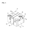
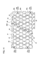
- Fig. 1 is an oblique view of a battery pack for the first embodiment of the present invention
- the battery pack of the present invention is primarily installed on-board an electric motor-bike to supply power to a motor that drives the bike.
- the present invention since the present invention has many batteries arrayed in multiple rows and columns to increase output, it is optimal for use in high output applications such as an electric vehicle.
- the battery pack of the present invention is most suitable for use as a power source in an electric vehicle such as an electric motor-bike (including an electric motor scooter and an electric motorcycle), a bicycle with electrical-assist, an electric wheel-chair, an electric three-wheeled vehicle, and an electric go-cart.
- an electric vehicle such as an electric motor-bike (including an electric motor scooter and an electric motorcycle), a bicycle with electrical-assist, an electric wheel-chair, an electric three-wheeled vehicle, and an electric go-cart.
- an electric motor-bike including an electric motor scooter and an electric motorcycle
- a bicycle with electrical-assist an electric wheel-chair
- an electric three-wheeled vehicle an electric go-cart.
- the following describes
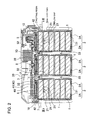
- the battery pack of Figs. 1-5 has a plurality of batteries 1 disposed in multiple rows and columns in battery holders 2 to form battery blocks 10, and a plurality of battery blocks 10 are housed in a battery case 3.
- the battery pack of the figures has three battery blocks 10 arranged in three parallel rows inside the battery case 3.
- the battery pack of the figures has battery blocks 10 housed in a plastic battery case 3, the battery pack of the present invention does not necessarily require containment of the battery blocks in a battery case.
- the battery blocks can be covered with an insulating film such as heat-shrink film, or the battery blocks can be embedded in potting resin without housing them in a battery case.
- a battery block 10 is provided with a plurality of batteries 1 that can be charged, and a battery holder 2 that disposes the batteries 1 in multiple rows and columns, and in parallel orientation.
- the battery block 10 of the figures is provided with a circuit board 5 connected to the batteries 1 via lead-plates 4, and the circuit board 5 is disposed in a fixed position on the battery holder 2.
- the batteries 1 are lithium ion rechargeable batteries. However, the batteries can also be nickel-hydride batteries or nickel-cadmium batteries. Further, although the batteries 1 in the battery pack of the figures are circular cylindrical batteries the batteries can also be rectangular batteries.
- the battery block 10 of the figures has batteries arranged in parallel orientation in multiple rows and columns, and the battery holder 2 retains each battery 1 in a fixed position with the end planes of each battery 1 aligned in the same plane.
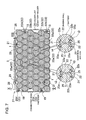
- the battery block 10 of the figures has a plurality of batteries 1 arranged in parallel orientation with ten batteries 1 arranged in a row and stacked in six rows to make a total array of sixty batteries 1. Specifically, the battery block 10 disposes batteries 1 in an array of six rows and ten columns.
- the battery block 10 of the figures has vertically adjacent batteries 1 offset to fill the valleys between batteries 1 and dispose the batteries 1 in zigzagging vertical columns.
- the battery block 10 of the figures disposes batteries 1 in six rows and ten columns, the present invention does not limit the number of batteries or the battery array configuration of the battery blocks.
- the battery pack of Figs. 2-5 has three battery blocks 10 housed in the battery case 3. Therefore, the battery pack is provided with a total of 180 batteries 1.
- the battery pack of the present invention does not specify the number of battery blocks housed in the battery case, and these types of specifications are set to numbers optimal for the application.
- a plurality of batteries 1 are connected in series and parallel by weld-attaching lead-plates 4 to both ends of each battery 1.
- the lead-plates 4 connect batteries 1 in the same row in series, and connect batteries 1 disposed in the same zigzagging column in parallel.
- the lead-plates 4 are metal plates welded to the electrode terminals at the ends of the batteries 1 to connect batteries 1 in the same column parallel. Since the battery block 10 of Figs. 6-9 has batteries 1 in the same column disposed in a zigzag pattern, the lead-plates 4 also have a zigzag shape.
- a lead-plate 4 that connects batteries 1 in adjacent columns in series has a zigzag shape and a width that can connect two columns of batteries 1 together. In the battery block 10 of Fig.
- lead-plates 4 connect ten batteries 1 in series and six batteries 1 in parallel. Specifically, sixty batteries 1 are connected ten in series and six in parallel by the lead-plates 4.
- the output voltage of the battery pack can be adjusted by the number of batteries 1 connected in series, and the output current can be adjusted by the number of batteries 1 connected in parallel. Since the battery block 10 of the figures has ten batteries 1 connected in series, output voltage is ten times the battery voltage. Accordingly, a battery block 10 that uses lithium ion batteries with a specified voltage of 3.7V has an output voltage of 37V.
- each lead-plate 4 is connected to the circuit board 5 mounted on the battery holder 2. This allows protection circuitry (not illustrated) on the circuit board 5 to detect the voltage of each battery 1.
- Each lead-plate 4 is provided with a connecting tab 4A protruding from one end that connects to the circuit board 5.
- Each lead-plate 4 has a lead-wire 6 connected to the connecting tab 4A to connect the lead-plates 4 to the circuit board 5 protection circuitry.
- a battery holder 2 is provided with insertion sections 21 separated by dividing walls 22 to insert and hold the batteries 1 in fixed positions. Batteries inserted in the insertion sections 21 make contact with the dividing walls 22 in a thermally coupled manner. Heat generated by the batteries 1 is transferred to, and dissipated in the battery holder 2.
- the battery holder 2 holds batteries 1 inserted in the insertion sections 21 in fixed positions.
- the battery holder 2 is fabricated by molding insulating plastic. Since the battery block 10 shown in the figures is provided with sixty batteries 1, the battery holder 2 is shaped with dividing walls 22 that establish sixty insertion sections 21 and is formed entirely from plastic as an integrated structure.
- the insertion sections 21 have both ends open to allow electrode terminals at the ends of the inserted batteries 1 to be exposed to the outside.
- the thickness of the battery holder 2 dividing walls 22 increases from the periphery regions to the center regions. Since the battery block 10 of Figs. 7 , 9 , and 11 has circular cylindrical batteries 1, the battery holder 2 insertion sections 21 are circular cylinders that conform to the battery 1 surfaces. In this battery holder 2, dividing wall 22 thickness varies with position, and adjacent circular cylindrical battery 1 surfaces are closest in regions where the dividing walls 22 are thinnest. The thin part 22a of the battery holder 2 dividing walls 22 becomes thicker at center regions than at periphery regions. In the battery holder 2 of Fig.
- the thin part 22a of the dividing walls 22 in this battery block 10 which has batteries 1 disposed in multiple rows, becomes thicker towards the center row of batteries 1, the thickness of the thin part 22b of dividing walls 22 in the same row is the same.
- the thickness of battery holder dividing walls in the same row can also vary to become thicker at the center than at the periphery.
- the heat capacity of dividing walls 22 thermally coupled with batteries 1 disposed in center regions is greater than the heat capacity of dividing walls 22 thermally coupled with batteries 1 disposed in periphery regions. This is because the heat capacity of the dividing walls 22 is proportional to the product of their specific heat and volume. Dividing walls 22 with large heat capacity can reduce the temperature rise corresponding to a given amount of heat energy absorbed from the batteries 1. Therefore, by making the heat capacity of dividing walls 22 thermally coupled with batteries 1 disposed in center regions greater than that of dividing walls 22 thermally coupled with batteries 1 disposed in periphery regions, the temperature rise of batteries 1 disposed in the center regions can be reduced.
- the temperature of batteries 1 in the periphery regions tends to be lower.
- the temperature of batteries 1 in the center regions has a tendency to become higher.
- the amount of battery 1 heat energy absorbed by dividing walls 22 at the center regions can be increased and the temperature rise of the center region batteries 1 can be reduced.
- temperature differences between batteries 1 disposed in the periphery regions and batteries 1 disposed in the center regions can be reduced.
- the battery pack of Figs. 2 and 3 has battery blocks 10 inserted in the battery case 3 and those battery blocks 10 are embedded in potting resin 7. All the batteries 1 can be completely embedded in potting resin 7 to thermally couple each battery 1 in an ideal manner with the battery case 3. However, it is not necessary to completely embed all the batteries 1 in potting resin 7. For example, a configuration that leaves part of the top row of batteries 1 just contacting the potting resin 7 is also possible. In a battery pack filled with potting resin 7, potting resin 7 can fill between the batteries 1 and the battery holder 2 insertion sections 21 to thermally couple the batteries 1 and the battery holders 2 in an ideal manner.
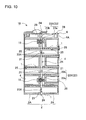
- the battery holder 2 shown in Figs. 6 , 8 , and 9 is divided into a pair of holder units 2A.
- the ends of each battery 1 are inserted into the insertion sections 21 of the separated holder units 2A to dispose the batteries 1 in fixed positions.
- Each holder unit 2A is provided with insertion sections 21 that can accept insertion of approximately half of each battery 1, and each battery 1 is inserted in a pair of holder units 2A to retain it in a fixed position.
- fasteners 23 are provided to set the relative position for joining the pair of holder units 2A.
- the fasteners 23 are configured to join a pair of holder units 2A in a manner that establishes flow gaps 24 that pass potting resin 7 between opposing surfaces of the holder units 2A.
- the fasteners 23 join a pair of holder units 2A in a manner that establishes flow gaps 24 between opposing surfaces that are for example, 1 mm to 10mm, preferably 2mm to 8mm, and more preferably 3mm to 6mm.
- the fasteners 23 shown in Fig. 10 are connecting bosses 23X that protrude from the opposing surfaces of a pair of holder units 2A.
- the fasteners 23, which are connecting bosses 23X are formed from plastic in single-piece construction with the holder units 2A.
- the connecting bosses 23X on one side have connecting projections 23a with circular cylindrical ends, and the ends of the connecting bosses 23X on the other side are provided with connecting cylinders 23b that accept insertion of the connecting projections 23a.
- These fasteners 23 join a pair of holder units 2A and establish flow gaps 24 by inserting the connecting projections 23a of the connecting bosses 23X on one side into the connecting cylinders 23b of the connecting bosses 23X on the other side.
- the holder units 2A have connecting bosses 23X established in the four corner regions of their opposing surfaces.
- the fasteners 23X are established in a plurality of locations to join the holder units 2A while forming flow gaps 24.
- the size of the flow gaps 24 can be set by the amount of protrusion of the connecting bosses 23X from the opposing surfaces of the holder units 2A. Specifically, the amount of protrusion of the connecting bosses 23X is a height that forms a given flow gap 24 width when the connecting projections 23a are inserted in the connecting cylinders 23b.
- a pair of holder units 2A connected via the fasteners 23 described above allows potting resin 7 filling the battery case 3 to flow smoothly from the flow gaps 24 into the insertion sections 21 and fill without forming vacancies.
- potting resin 7 can fill between the batteries 1 and the insertion sections 21 without forming vacancies.
- each holder unit 2A insertion section 21 tapers from holder unit 2A opposing surfaces, which have flow gaps 24 established, towards the battery 1 end regions. Specifically, by tapering the insides of the insertion sections 21 from the center of the battery holder 2 towards both end regions, potting resin 7 flowing in from the flow gaps 24 can be introduced more smoothly into the insertion sections 21.
- the insertion sections 21 that dispose the circular cylindrical batteries 1 in fixed positions have circular cylindrical shapes, the inside diameter of the insertion sections 21 becomes smaller from the center region towards both end regions, and the inside diameter of both ends of the insertion sections 21 is approximately equal to the outside diameter of the batteries 1 to retain the batteries 1 accurately in fixed positions.
- batteries 1 can also be smoothly inserted into each holder unit 2A insertion section 21. Further, with the batteries 1 inserted in the insertion sections 21, both ends of the batteries 1 contact the inside surfaces of the insertion sections 21 to hold the batteries 1 in fixed positions.
- a battery holder 2 with potting resin 7 that fills the insertion sections 21 can be provided with filling grooves 25 on the insides surfaces of the insertion sections 21 extending in the lengthwise direction of the batteries 1.
- the filling grooves 25 are provided in a plurality of rows on the inside surface of each insertion section 21.
- potting resin 7 in a viscous fluid state introduced from the flow gaps 24 between the holder units 2A can flow into the filling grooves 25 to smoothly fill the space between the batteries 1 and the insertion sections 21 without vacancies.
- the battery holder 2 has lead-plates 4 disposed at the openings established at both ends of the insertion sections 21.
- the lead-plates 4 are disposed outside the insertion sections 21 and are weld-attached to the ends of the batteries 21 exposed outside the open ends of the insertion sections 21.
- the battery holder 2 of Figs. 6 and 8 is provided with alignment cavities 26 at the open ends of the insertion sections 21 that mate with the lead-plates 4, and the lead-plates 4 are fitted into those alignment cavities 26 and held in fixed positions.
- the shape of the alignment cavities 26 is made slightly larger than the outline of the lead-plates 4, and the lead-plates 4 are inserted in the alignment cavities 26 and disposed in fixed positions.
- a battery holder 2 that is formed in separate pieces is connected by screwing set screws 19 into the connecting bosses 23X, which are formed in single-piece construction.
- the battery holder 2 of Fig. 9 is provided with connecting bosses 23X formed in single-piece construction at the perimeter of the battery holder 2.
- the connecting bosses 23X have cylindrical shapes and set screws 19 are inserted inside the cylindrical connecting bosses 23X.
- a battery holder 2 formed in separate pieces can also be joined in a locking fit configuration, joined by bonding, or joined by a combination of these methods.
- the battery pack of the present invention does not limit the battery holder to that structure.
- the battery holder can also be any other structure that can dispose a plurality of batteries in fixed positions in insertion sections.
- the battery holder can also be a single piece that does not divide into sub-components, or it can be a structure made up of two or more separate pieces.
- the battery pack of the present invention does not necessarily require the batteries to be embedded in potting resin. In this type of battery pack, contact surface area of the batteries and the inside surfaces of the battery holder insertion sections is increased to thermally couple the batteries and the battery holder.
- the battery block 10 of Figs. 6 and 7 has a circuit board 5 mounted on its top surface.
- the battery block 10 of the figures which has batteries 1 oriented horizontally, has the circuit board 5 disposed in a horizontal orientation.
- the battery holder 2 shown in the figures is provided with a circuit board mounting section 27 that aligns the circuit board 5 in a fixed position.
- the battery holder 2 shown in the figures has alignment ribs 28 formed in single-piece construction projecting upward around the perimeter of the top surface to establish the circuit board mounting section 27.
- the battery holder 2 of the figures is a pair of battery holders 2A joined together and alignment ribs 28 are provided around the top surface perimeter edges of each holder unit 2A except along opposing edges. This allows the circuit board 5 to be disposed on the top surface of the battery holder 2.
- the circuit board mounting section 27 alignment rib 28 outline has a shape that conforms to the perimeter of the circuit board 5.
- the battery holder 2 shown in the figures is provided with connecting bosses 29 formed in single-piece construction that protrude from the top surface.
- the circuit board 5 is mounted on the connecting bosses 29 via set screws 18 to dispose the circuit board 5 in a position separated from the top surface of the battery holder 2.
- the circuit board 5 can have electronic components (not illustrated) mounted on the side opposite the battery holder 2 to implement circuitry such as protection circuitry.
- the circuit board can also be mounted on the battery holder in a locking fit configuration instead of using set screws.
- alignment ribs 28 opposite edges on both sides of the circuit board 5 are provided with cut-outs 28A to run circuit board 5 lead-wires 6 off the circuit board 5.
- the cut-outs 28A are provided in positions corresponding to the positions of the lead-wires 6 attached to the circuit board 5.
- the lead-wires 6 can be disposed without running them over the tops of the alignment ribs 28.
- the lead-wires 6 extending off the circuit board 5 through the cut-outs 28A are connected to the connecting tabs 4A on the lead-plates 4 to connect the lead-plates 4 to the circuit board 5.
- the circuit board 5 is connected to the batteries 1 via the lead-wires 6 and the lead-plates 4.
- the circuit board 5 implements circuitry such as control circuitry (not illustrated) that detects the voltage of each battery 1 and controls charging and discharging of the plurality of batteries 1, and protection circuitry (not illustrated) that cuts-off charging and discharging current.
- the protection circuitry switches a switching device OFF to cut-off discharging current when the voltage of any battery drops below a minimum voltage. Protection circuitry also switches a switching device OFF to stop charging when the voltage of any battery becomes greater than a maximum voltage.
- a battery pack having protection circuitry implemented to detect the voltage of each battery and control charging and discharging can be operated safely while protecting the batteries 1.
- circuit board 5 also implements temperature detection circuitry that detects abnormal battery 1 temperature.
- Circuit board 5 temperature detection circuitry detects abnormal battery 1 temperature rise and controls battery 1 charging and discharging by operations such as restraining battery 1 charging and discharging current or stopping charging and discharging.
- the battery case 3 is fabricated by molding plastic.
- the battery case 3 of Figs. 2-5 is formed in a box shape with an open top.
- This battery case 3 houses three battery blocks 10 arranged in parallel orientation and has hollow partitions 32 provided between the three battery blocks 10 for cooling.
- the hollow partitions 32 extend upward from the bottom panel 31 of the battery case 3, and hollow regions 33 open at the bottom are established inside the hollow partitions 32.
- These hollow partitions 32 are in close proximity to the battery blocks 10 disposed on both sides, are thermally coupled to the battery blocks 10, and radiate battery block 10 heat outside the battery case 3.
- the hollow partitions 32 increase the heat radiating surface area in contact with the ambient air to efficiently radiate battery 1 heat to the outside.
- the hollow partitions 32 can suppress conditions that induce thermal runaway of the battery blocks 10 disposed on both sides of the hollow partitions 32. This is because abnormal temperature rise in a battery block 10 on one side of a hollow partition 32 is isolated by the hollow region 33 inside the hollow partition 32.
- the battery pack of the figures is provided with a connecting plate 40 that connects a plurality of battery blocks 10.
- the connecting plate 40 is disposed on the top surfaces of the plurality of battery blocks 10, is attached to each battery block 10 via set screws (not illustrated), and joins the plurality of battery blocks 10 as a single unit. Since the battery blocks 10 of the figures have circuit boards 5 mounted on their top surfaces, the circuit boards 5 are disposed between the connecting plate 40 and the battery holders 2 and are protected by the connecting plate 40.
- the plurality of battery blocks 10 can be joined as a single unit by the connecting plate 40 and housed in the battery case 3 while protecting the circuit boards 5 with the connecting plate 40.
- the connecting plate 40 is fabricated by molding plastic.
- the connecting plate 40 of Fig. 4 has perimeter walls 42 formed in single-piece construction projecting upward and downward along the perimeter of a base plate 41, which is disposed opposite the top surfaces of the plurality of battery blocks 10.
- the perimeter walls 42 have an outline that conforms to the inside surfaces of the open top of the battery case 3 to fit the connecting plate 40 inside the edges of the open region of the battery case 3.
- the connecting plate 40 has a primary circuit board 60 mounted on its upper surface.
- the primary circuit board 60 is connected to the circuit boards 5 mounted on each battery block 10 via lead-wires (not illustrated).
- the primary circuit board 60 implements protection circuitry (not illustrated) that inputs signals from each circuit board 5 and controls battery 1 charging and discharging.
- Electronic components (not illustrated) are mounted on the primary circuit board 60 to implement circuitry such as switching devices that control discharging current based on signals input from the circuit boards 5, and relay control circuitry that controls battery 1 current.
- a switching device can be switched OFF to cut-off battery 1 current when the voltage of any battery 1 becomes greater than a maximum voltage, when the voltage of any battery 1 becomes less than a minimum voltage, when battery 1 temperature becomes greater than a maximum temperature, or when battery 1 temperature becomes less than a minimum temperature.
- a battery pack which detects parameters such as the voltage and temperature of each battery 1 and controls battery current, can be safely operated while protecting the batteries 1.
- the plurality of battery blocks 10 are joined as a unit by the connecting plate 40 and held in a battery case 3.
- a battery case 3 divided by hollow partitions 32 houses a battery block 10 in each partitioned section.
- the connecting plate 40 that joins the plurality of battery blocks 10 is fit into the open region of the battery case 3 and held in place by set screws (not illustrated).
- the battery pack is filled with potting resin 7 in a manner that embeds the battery blocks 10, and more specifically embeds the batteries 1, housed in the battery case 3.
- the potting resin 7 is a resin such as urethane resin, epoxy resin, or silicone resin that is introduced in the unhardened viscous fluid state to embed the batteries 1 and battery holders 2.
- potting resin 7 adheres closely to the inside surfaces of the battery case 3 without forming vacancies to form ideal thermal coupling between the potting resin 7 and the battery case 3.
- a battery pack with batteries embedded in potting resin can also be formed by inserting the battery blocks in shaping containers, filling the shaping containers with potting resin, removing the battery blocks from the shaping containers after potting resin hardening, and inserting the battery blocks in the battery case.
- the inside shape of the shaping containers equivalent to the inside shape of the battery case, the potting resin can make close contact with the inside surfaces of the battery case. Since the battery blocks embedded in potting resin in this battery pack can be removed from the battery case, it has the feature that maintenance such as battery block replacement can be performed.
- the battery pack described above is assembled in the following manner.
Landscapes
- Chemical & Material Sciences (AREA)
- Chemical Kinetics & Catalysis (AREA)
- Electrochemistry (AREA)
- General Chemical & Material Sciences (AREA)
- Manufacturing & Machinery (AREA)
- Engineering & Computer Science (AREA)
- General Physics & Mathematics (AREA)
- Mathematical Analysis (AREA)
- Mathematical Optimization (AREA)
- Pure & Applied Mathematics (AREA)
- Algebra (AREA)
- Physics & Mathematics (AREA)
- Battery Mounting, Suspending (AREA)
- Secondary Cells (AREA)
Abstract
Description
- The present invention relates to a battery pack having many batteries disposed in multiple rows and columns, and in particular to a battery pack optimal for use on-board an electric vehicle such as an electric motor-bike (e.g. electric motor scooter and electric motorcycle) as a power source to supply high power to a driving motor.
- A battery pack used in high power applications such as in an electric motor-bike has many batteries disposed in multiple rows and columns connected in series and parallel. This type of battery pack has a plurality of batteries connected in series to increase output voltage, and connected in parallel to increase output current. A battery pack used in high output applications is charged and discharged with high currents causing battery temperature to rise. Battery electrical characteristics change with temperature. If temperature differences develop in a battery pack housing a plurality of batteries, those temperature differences result in non-uniform battery characteristics. Battery characteristic non-uniformity accelerates degradation of a given battery, and shortens the life-time of the entire battery pack. This is because battery characteristic non-uniformity causes remaining battery capacity differences, and remaining battery capacity differences make it easy to overcharge or over-discharge a given battery. Since battery degradation is accelerated by over-charging and over-discharging, a given battery degrades under these conditions and the life-time of the entire battery pack is shortened. A battery pack having a structure intended to reduce battery temperature differences has been developed to prevent this detrimental effect. (Refer to Japanese Laid-Open Patent Publication
2009-4163 - In the battery pack of
JP 2009-4163-A 2003-77440 - In the battery pack of
JP 2009-4163-A - In the battery pack of
JP 2003-77440-A - The present invention was developed with the object of correcting the drawbacks of the battery packs described above. Thus, it is a primary object of the present invention to provide a battery pack that can reduce battery temperature differences while allowing inexpensive manufacture in quantity. Further, it is another important object of the present invention to provide a battery pack that can reduce temperature differences between individual batteries with battery holders that dispose many batteries in multiple rows and columns.
- The battery pack of the present invention is provided with a plurality of
batteries 1 that can be charged, andbattery holders 2 that dispose thebatteries 1 in multiple rows and columns and in parallel orientation. Thebattery holders 2 are provided withinsertion sections 21 separated by dividingwalls 22 wherebatteries 1 are inserted and held in fixed positions. Eachbattery 1 contacts the dividingwalls 22 in a thermally coupled manner to transfer and dissipate heat generated by thebatteries 1 to thebattery holders 2. Further, the thickness of thebattery holder 2 dividingwalls 22 increases from the periphery regions to the center regions to make the heat capacity of the dividingwalls 22 thermally coupled withbatteries 1 disposed in center regions of thebattery holders 2 greater than the heat capacity of the dividingwalls 22 thermally coupled withbatteries 1 disposed in periphery regions of thebattery holders 2. - The battery pack described above can reduce battery temperature differences while having a simple structure that can be inexpensively manufactured in quantity. Further, the battery pack has the characteristic that temperature differences between individual batteries can be reduced with battery holders that dispose many batteries in multiple rows and columns.
- The battery pack of the present invention has
batteries 1 that are circular cylindrical batteries, andbattery holder 2insertion sections 21 that are circular cylinders conforming to thebattery 1 surfaces. The thinnest part of theinsertion section 21 dividingwalls 22 can be made thicker in center regions of thebattery holders 2 than in periphery regions. In this battery pack, circular cylindrical batteries can be thermally coupled with the dividing walls to reduce circular cylindrical battery temperature differences. - In the battery pack of the present invention, the
battery holders 2 can be made of insulating plastic. In this battery pack, heat generated by each battery can be dissipated to the dividing walls to reduce battery temperature differences while insulating adjacent batteries via the battery holders. - In the battery pack of the present invention, space between the
batteries 1 and thebattery holders 2 can be filled withpotting resin 7. In this battery pack, thermal coupling between the batteries and the battery holders can be further improved via the potting resin. Consequently, battery heat can be efficiently transferred to and dissipated in the battery holder dividing walls. - In the battery pack of the present invention, a
battery case 3 can be provided to house thebattery holders 2, and the inside of thebattery case 3 can be filled withpotting resin 7 to embed thebatteries 1 inpotting resin 7. Since the batteries in this battery pack are embedded in potting resin, the battery heat dissipating area is increased, and heat generated by the batteries can be efficiently dissipated. - In the battery pack of the present invention, each
battery holder 2 can be configured as a pair ofseparate holder units 2A, and the ends of eachbattery 1 can be inserted ininsertion sections 21 in theseparate holder units 2A to dispose thebatteries 1 in fixed positions. Further,fasteners 23 can be provided to fix the relative connecting position of a pair ofholder units 2A, and the battery pack can be configured to join each pair ofholder units 2A via thefasteners 23 while establishingflow gaps 24 that passpotting resin 7 through opposing surfaces of theholder units 2A. Each pair ofholder units 2A can be joined viafasteners 23 establishingflow gaps 24, and potting resin introduced into thebattery case 3 can flow through theflow gaps 24 into eachholder unit 2Ainsertion section 21. - In this battery pack, potting resin can be introduced into the battery case to fill regions between the batteries and the battery holders without vacancies to thermally couple the batteries and the battery holders in an ideal manner. In particular, in an array of many batteries in multiple rows and columns, potting resin can be smoothly introduced between each battery and its insertion section without vacancies to thermally couple all the batteries in an ideal manner with the battery holders.
- In the battery pack of the present invention, the
fasteners 23 can be connectingbosses 23X that protrude from opposing surfaces of a pair ofholder units 2A. The connectingbosses 23X on one side can be inserted in the connectingbosses 23X on the other side to join the pair ofholder units 2A in a manner that establishesflow gaps 24. In this battery pack, pairs of holder units can be simply, easily, and accurately joined in a manner establishing flow gaps. Therefore, connected pairs of holder units can be loaded in the battery case and potting resin can be introduced to fill between the batteries and the battery holders without vacancies. - The above and further objects of the present invention as well as the features thereof will become more apparent from the following detailed description to be made in conjunction with the accompanying drawings.
-
Fig. 1 is an oblique view of a battery pack for the first embodiment of the present invention; -
Fig. 2 is a cross-section through the line II-II of the battery pack shown inFig. 1 ; -
Fig. 3 is a cross-section through the line III-III of the battery pack shown inFig. 2 ; -
Fig. 4 is an exploded oblique view of the battery pack shown inFig. 1 ; -
Fig. 5 is an exploded oblique view of the battery case and battery blocks of the battery pack shown inFig. 4 ; -
Fig. 6 is an oblique view of a battery block; -
Fig. 7 is a vertical cross-section of the battery block shown inFig. 6 ; -
Fig. 8 is an exploded oblique view of the battery block shown inFig. 6 ; -
Fig. 9 is an exploded oblique view of the battery holder of the battery block shown inFig. 8 ; -
Fig. 10 is a cross-section through the line X-X of the battery block shown inFig. 7 ; and -
Fig. 11 is a front view from the inside of a holder unit of the battery holder shown inFig. 9 . - The following describes embodiments of the present invention based on the figures.
- The battery pack of the present invention is primarily installed on-board an electric motor-bike to supply power to a motor that drives the bike. In particular, since the present invention has many batteries arrayed in multiple rows and columns to increase output, it is optimal for use in high output applications such as an electric vehicle. Accordingly, the battery pack of the present invention is most suitable for use as a power source in an electric vehicle such as an electric motor-bike (including an electric motor scooter and an electric motorcycle), a bicycle with electrical-assist, an electric wheel-chair, an electric three-wheeled vehicle, and an electric go-cart. The following describes in detail embodiments of a battery pack used in an electric motor-bike. However, the battery pack of the present invention is in no way limited to electric motor-bike applications.
- The battery pack of
Figs. 1-5 has a plurality ofbatteries 1 disposed in multiple rows and columns inbattery holders 2 to form battery blocks 10, and a plurality of battery blocks 10 are housed in abattery case 3. The battery pack of the figures has threebattery blocks 10 arranged in three parallel rows inside thebattery case 3. Although the battery pack of the figures has battery blocks 10 housed in aplastic battery case 3, the battery pack of the present invention does not necessarily require containment of the battery blocks in a battery case. For example, the battery blocks can be covered with an insulating film such as heat-shrink film, or the battery blocks can be embedded in potting resin without housing them in a battery case. - As shown in
Figs. 6-10 , abattery block 10 is provided with a plurality ofbatteries 1 that can be charged, and abattery holder 2 that disposes thebatteries 1 in multiple rows and columns, and in parallel orientation. In addition, thebattery block 10 of the figures is provided with acircuit board 5 connected to thebatteries 1 via lead-plates 4, and thecircuit board 5 is disposed in a fixed position on thebattery holder 2. - The
batteries 1 are lithium ion rechargeable batteries. However, the batteries can also be nickel-hydride batteries or nickel-cadmium batteries. Further, although thebatteries 1 in the battery pack of the figures are circular cylindrical batteries the batteries can also be rectangular batteries. Thebattery block 10 of the figures has batteries arranged in parallel orientation in multiple rows and columns, and thebattery holder 2 retains eachbattery 1 in a fixed position with the end planes of eachbattery 1 aligned in the same plane. Thebattery block 10 of the figures has a plurality ofbatteries 1 arranged in parallel orientation with tenbatteries 1 arranged in a row and stacked in six rows to make a total array of sixtybatteries 1. Specifically, thebattery block 10 disposesbatteries 1 in an array of six rows and ten columns. Thebattery block 10 of the figures has verticallyadjacent batteries 1 offset to fill the valleys betweenbatteries 1 and dispose thebatteries 1 in zigzagging vertical columns. Although thebattery block 10 of the figures disposesbatteries 1 in six rows and ten columns, the present invention does not limit the number of batteries or the battery array configuration of the battery blocks. - The battery pack of
Figs. 2-5 has threebattery blocks 10 housed in thebattery case 3. Therefore, the battery pack is provided with a total of 180batteries 1. However, the battery pack of the present invention does not specify the number of battery blocks housed in the battery case, and these types of specifications are set to numbers optimal for the application. - A plurality of
batteries 1 are connected in series and parallel by weld-attaching lead-plates 4 to both ends of eachbattery 1. The lead-plates 4connect batteries 1 in the same row in series, and connectbatteries 1 disposed in the same zigzagging column in parallel. The lead-plates 4 are metal plates welded to the electrode terminals at the ends of thebatteries 1 to connectbatteries 1 in the same column parallel. Since thebattery block 10 ofFigs. 6-9 hasbatteries 1 in the same column disposed in a zigzag pattern, the lead-plates 4 also have a zigzag shape. A lead-plate 4 that connectsbatteries 1 in adjacent columns in series has a zigzag shape and a width that can connect two columns ofbatteries 1 together. In thebattery block 10 ofFig. 8 , lead-plates 4 connect tenbatteries 1 in series and sixbatteries 1 in parallel. Specifically, sixtybatteries 1 are connected ten in series and six in parallel by the lead-plates 4. The output voltage of the battery pack can be adjusted by the number ofbatteries 1 connected in series, and the output current can be adjusted by the number ofbatteries 1 connected in parallel. Since thebattery block 10 of the figures has tenbatteries 1 connected in series, output voltage is ten times the battery voltage. Accordingly, abattery block 10 that uses lithium ion batteries with a specified voltage of 3.7V has an output voltage of 37V. - In the
battery block 10 of the figures, each lead-plate 4 is connected to thecircuit board 5 mounted on thebattery holder 2. This allows protection circuitry (not illustrated) on thecircuit board 5 to detect the voltage of eachbattery 1. Each lead-plate 4 is provided with a connectingtab 4A protruding from one end that connects to thecircuit board 5. Each lead-plate 4 has a lead-wire 6 connected to the connectingtab 4A to connect the lead-plates 4 to thecircuit board 5 protection circuitry. - As shown in
Figs. 7 ,9 , and11 , abattery holder 2 is provided withinsertion sections 21 separated by dividingwalls 22 to insert and hold thebatteries 1 in fixed positions. Batteries inserted in theinsertion sections 21 make contact with the dividingwalls 22 in a thermally coupled manner. Heat generated by thebatteries 1 is transferred to, and dissipated in thebattery holder 2. Thebattery holder 2 holdsbatteries 1 inserted in theinsertion sections 21 in fixed positions. Thebattery holder 2 is fabricated by molding insulating plastic. Since thebattery block 10 shown in the figures is provided with sixtybatteries 1, thebattery holder 2 is shaped with dividingwalls 22 that establish sixtyinsertion sections 21 and is formed entirely from plastic as an integrated structure. Theinsertion sections 21 have both ends open to allow electrode terminals at the ends of the insertedbatteries 1 to be exposed to the outside. - The thickness of the
battery holder 2dividing walls 22 increases from the periphery regions to the center regions. Since thebattery block 10 ofFigs. 7 ,9 , and11 has circularcylindrical batteries 1, thebattery holder 2insertion sections 21 are circular cylinders that conform to thebattery 1 surfaces. In thisbattery holder 2, dividingwall 22 thickness varies with position, and adjacent circularcylindrical battery 1 surfaces are closest in regions where the dividingwalls 22 are thinnest. Thethin part 22a of thebattery holder 2dividing walls 22 becomes thicker at center regions than at periphery regions. In thebattery holder 2 ofFig. 11 , thethin part 22a of the dividingwalls 22 becomes gradually thicker from the periphery to the center with thickness varying from t1=1.5mm, to t2=2.0mm, t3=2.5mm, and t4=3.0mm. Although thethin part 22a of the dividingwalls 22 in thisbattery block 10, which hasbatteries 1 disposed in multiple rows, becomes thicker towards the center row ofbatteries 1, the thickness of thethin part 22b of dividingwalls 22 in the same row is the same. However, the thickness of battery holder dividing walls in the same row can also vary to become thicker at the center than at the periphery. - In a
battery holder 2 withthicker dividing walls 22 at the center regions than at the periphery regions, the heat capacity of dividingwalls 22 thermally coupled withbatteries 1 disposed in center regions is greater than the heat capacity of dividingwalls 22 thermally coupled withbatteries 1 disposed in periphery regions. This is because the heat capacity of the dividingwalls 22 is proportional to the product of their specific heat and volume. Dividingwalls 22 with large heat capacity can reduce the temperature rise corresponding to a given amount of heat energy absorbed from thebatteries 1. Therefore, by making the heat capacity of dividingwalls 22 thermally coupled withbatteries 1 disposed in center regions greater than that of dividingwalls 22 thermally coupled withbatteries 1 disposed in periphery regions, the temperature rise ofbatteries 1 disposed in the center regions can be reduced. Since heat is radiated to the outside from the periphery regions of thebattery holder 22, the temperature ofbatteries 1 in the periphery regions tends to be lower. In other words, the temperature ofbatteries 1 in the center regions has a tendency to become higher. However, in abattery holder 2 with higher heatcapacity dividing walls 22 in the center regions, the amount ofbattery 1 heat energy absorbed by dividingwalls 22 at the center regions can be increased and the temperature rise of thecenter region batteries 1 can be reduced. As a result, temperature differences betweenbatteries 1 disposed in the periphery regions andbatteries 1 disposed in the center regions can be reduced. - The battery pack of
Figs. 2 and3 has battery blocks 10 inserted in thebattery case 3 and those battery blocks 10 are embedded inpotting resin 7. All thebatteries 1 can be completely embedded inpotting resin 7 to thermally couple eachbattery 1 in an ideal manner with thebattery case 3. However, it is not necessary to completely embed all thebatteries 1 inpotting resin 7. For example, a configuration that leaves part of the top row ofbatteries 1 just contacting thepotting resin 7 is also possible. In a battery pack filled withpotting resin 7, pottingresin 7 can fill between thebatteries 1 and thebattery holder 2insertion sections 21 to thermally couple thebatteries 1 and thebattery holders 2 in an ideal manner. To smoothly fillbattery holder 2insertion sections 21 without vacancies withpotting resin 7 in a viscous fluid state, thebattery holder 2 shown inFigs. 6 ,8 , and9 is divided into a pair ofholder units 2A. In thisbattery holder 2, the ends of eachbattery 1 are inserted into theinsertion sections 21 of the separatedholder units 2A to dispose thebatteries 1 in fixed positions. Eachholder unit 2A is provided withinsertion sections 21 that can accept insertion of approximately half of eachbattery 1, and eachbattery 1 is inserted in a pair ofholder units 2A to retain it in a fixed position. Further, to smoothly fill without vacancies the space betweenholder unit 2A insertion sections 21 andbatteries 1 withpotting resin 7,fasteners 23 are provided to set the relative position for joining the pair ofholder units 2A. - The
fasteners 23 are configured to join a pair ofholder units 2A in a manner that establishesflow gaps 24 that passpotting resin 7 between opposing surfaces of theholder units 2A. Thefasteners 23 join a pair ofholder units 2A in a manner that establishesflow gaps 24 between opposing surfaces that are for example, 1 mm to 10mm, preferably 2mm to 8mm, and more preferably 3mm to 6mm. Thefasteners 23 shown inFig. 10 are connectingbosses 23X that protrude from the opposing surfaces of a pair ofholder units 2A. Thefasteners 23, which are connectingbosses 23X, are formed from plastic in single-piece construction with theholder units 2A. The connectingbosses 23X on one side have connectingprojections 23a with circular cylindrical ends, and the ends of the connectingbosses 23X on the other side are provided with connectingcylinders 23b that accept insertion of the connectingprojections 23a. Thesefasteners 23 join a pair ofholder units 2A and establishflow gaps 24 by inserting the connectingprojections 23a of the connectingbosses 23X on one side into the connectingcylinders 23b of the connectingbosses 23X on the other side. Theholder units 2A have connectingbosses 23X established in the four corner regions of their opposing surfaces. Thefasteners 23X are established in a plurality of locations to join theholder units 2A while formingflow gaps 24. The size of theflow gaps 24 can be set by the amount of protrusion of the connectingbosses 23X from the opposing surfaces of theholder units 2A. Specifically, the amount of protrusion of the connectingbosses 23X is a height that forms a givenflow gap 24 width when the connectingprojections 23a are inserted in the connectingcylinders 23b. - A pair of
holder units 2A connected via thefasteners 23 described above allows pottingresin 7 filling thebattery case 3 to flow smoothly from theflow gaps 24 into theinsertion sections 21 and fill without forming vacancies. In particular, with longnarrow batteries 1 inserted in theinsertion sections 21, pottingresin 7 can fill between thebatteries 1 and theinsertion sections 21 without forming vacancies. - Further, as shown by the broken lines indicating battery outlines in
Fig. 10 , the shape of the inside of eachholder unit 2A insertion section 21 tapers fromholder unit 2A opposing surfaces, which haveflow gaps 24 established, towards thebattery 1 end regions. Specifically, by tapering the insides of theinsertion sections 21 from the center of thebattery holder 2 towards both end regions, pottingresin 7 flowing in from theflow gaps 24 can be introduced more smoothly into theinsertion sections 21. Theinsertion sections 21 that dispose the circularcylindrical batteries 1 in fixed positions have circular cylindrical shapes, the inside diameter of theinsertion sections 21 becomes smaller from the center region towards both end regions, and the inside diameter of both ends of theinsertion sections 21 is approximately equal to the outside diameter of thebatteries 1 to retain thebatteries 1 accurately in fixed positions. In addition to allowingpotting resin 7 to smoothly fill theseinsertion sections 21,batteries 1 can also be smoothly inserted into eachholder unit 2A insertion section 21. Further, with thebatteries 1 inserted in theinsertion sections 21, both ends of thebatteries 1 contact the inside surfaces of theinsertion sections 21 to hold thebatteries 1 in fixed positions. - Further, as shown in
Fig. 7 , abattery holder 2 withpotting resin 7 that fills theinsertion sections 21 can be provided with fillinggrooves 25 on the insides surfaces of theinsertion sections 21 extending in the lengthwise direction of thebatteries 1. The fillinggrooves 25 are provided in a plurality of rows on the inside surface of eachinsertion section 21. In thisbattery holder 2, pottingresin 7 in a viscous fluid state introduced from theflow gaps 24 between theholder units 2A can flow into the fillinggrooves 25 to smoothly fill the space between thebatteries 1 and theinsertion sections 21 without vacancies. - In addition, the
battery holder 2 has lead-plates 4 disposed at the openings established at both ends of theinsertion sections 21. The lead-plates 4 are disposed outside theinsertion sections 21 and are weld-attached to the ends of thebatteries 21 exposed outside the open ends of theinsertion sections 21. Thebattery holder 2 ofFigs. 6 and8 is provided withalignment cavities 26 at the open ends of theinsertion sections 21 that mate with the lead-plates 4, and the lead-plates 4 are fitted into thosealignment cavities 26 and held in fixed positions. The shape of thealignment cavities 26 is made slightly larger than the outline of the lead-plates 4, and the lead-plates 4 are inserted in thealignment cavities 26 and disposed in fixed positions. - As shown in
Fig. 10 , abattery holder 2 that is formed in separate pieces is connected by screwing setscrews 19 into the connectingbosses 23X, which are formed in single-piece construction. Thebattery holder 2 ofFig. 9 is provided with connectingbosses 23X formed in single-piece construction at the perimeter of thebattery holder 2. The connectingbosses 23X have cylindrical shapes and setscrews 19 are inserted inside the cylindrical connectingbosses 23X. However, although not illustrated, abattery holder 2 formed in separate pieces can also be joined in a locking fit configuration, joined by bonding, or joined by a combination of these methods. - Although the
battery holder 2 described above is formed from plastic in two separate pieces, the battery pack of the present invention does not limit the battery holder to that structure. The battery holder can also be any other structure that can dispose a plurality of batteries in fixed positions in insertion sections. For example, the battery holder can also be a single piece that does not divide into sub-components, or it can be a structure made up of two or more separate pieces. Further, the battery pack of the present invention does not necessarily require the batteries to be embedded in potting resin. In this type of battery pack, contact surface area of the batteries and the inside surfaces of the battery holder insertion sections is increased to thermally couple the batteries and the battery holder. - The
battery block 10 ofFigs. 6 and7 has acircuit board 5 mounted on its top surface. Thebattery block 10 of the figures, which hasbatteries 1 oriented horizontally, has thecircuit board 5 disposed in a horizontal orientation. Thebattery holder 2 shown in the figures is provided with a circuitboard mounting section 27 that aligns thecircuit board 5 in a fixed position. Thebattery holder 2 shown in the figures hasalignment ribs 28 formed in single-piece construction projecting upward around the perimeter of the top surface to establish the circuitboard mounting section 27. Thebattery holder 2 of the figures is a pair ofbattery holders 2A joined together andalignment ribs 28 are provided around the top surface perimeter edges of eachholder unit 2A except along opposing edges. This allows thecircuit board 5 to be disposed on the top surface of thebattery holder 2. To align and dispose thecircuit board 5 inside thealignment ribs 28, the circuitboard mounting section 27alignment rib 28 outline has a shape that conforms to the perimeter of thecircuit board 5. Further, thebattery holder 2 shown in the figures is provided with connectingbosses 29 formed in single-piece construction that protrude from the top surface. Thecircuit board 5 is mounted on the connectingbosses 29 viaset screws 18 to dispose thecircuit board 5 in a position separated from the top surface of thebattery holder 2. Thecircuit board 5 can have electronic components (not illustrated) mounted on the side opposite thebattery holder 2 to implement circuitry such as protection circuitry. Although not illustrated, the circuit board can also be mounted on the battery holder in a locking fit configuration instead of using set screws. - Further, in the
battery holder 2 of the figures,alignment ribs 28 opposite edges on both sides of thecircuit board 5 are provided with cut-outs 28A to runcircuit board 5 lead-wires 6 off thecircuit board 5. The cut-outs 28A are provided in positions corresponding to the positions of the lead-wires 6 attached to thecircuit board 5. In thisbattery holder 2, by running the lead-wires 6 off both sides of thecircuit board 5 through the cut-outs 28A, the lead-wires 6 can be disposed without running them over the tops of thealignment ribs 28. The lead-wires 6 extending off thecircuit board 5 through the cut-outs 28A are connected to the connectingtabs 4A on the lead-plates 4 to connect the lead-plates 4 to thecircuit board 5. - The
circuit board 5 is connected to thebatteries 1 via the lead-wires 6 and the lead-plates 4. Thecircuit board 5 implements circuitry such as control circuitry (not illustrated) that detects the voltage of eachbattery 1 and controls charging and discharging of the plurality ofbatteries 1, and protection circuitry (not illustrated) that cuts-off charging and discharging current. The protection circuitry switches a switching device OFF to cut-off discharging current when the voltage of any battery drops below a minimum voltage. Protection circuitry also switches a switching device OFF to stop charging when the voltage of any battery becomes greater than a maximum voltage. A battery pack having protection circuitry implemented to detect the voltage of each battery and control charging and discharging can be operated safely while protecting thebatteries 1. Further, thecircuit board 5 also implements temperature detection circuitry that detectsabnormal battery 1 temperature.Circuit board 5 temperature detection circuitry detectsabnormal battery 1 temperature rise and controlsbattery 1 charging and discharging by operations such as restrainingbattery 1 charging and discharging current or stopping charging and discharging. - The
battery case 3 is fabricated by molding plastic. Thebattery case 3 ofFigs. 2-5 is formed in a box shape with an open top. Thisbattery case 3 houses threebattery blocks 10 arranged in parallel orientation and hashollow partitions 32 provided between the threebattery blocks 10 for cooling. Thehollow partitions 32 extend upward from thebottom panel 31 of thebattery case 3, andhollow regions 33 open at the bottom are established inside thehollow partitions 32. Thesehollow partitions 32 are in close proximity to the battery blocks 10 disposed on both sides, are thermally coupled to the battery blocks 10, andradiate battery block 10 heat outside thebattery case 3. In particular, thehollow partitions 32 increase the heat radiating surface area in contact with the ambient air to efficientlyradiate battery 1 heat to the outside. Further, as a result of the thermal insulating properties of thehollow regions 33, thehollow partitions 32 can suppress conditions that induce thermal runaway of the battery blocks 10 disposed on both sides of thehollow partitions 32. This is because abnormal temperature rise in abattery block 10 on one side of ahollow partition 32 is isolated by thehollow region 33 inside thehollow partition 32. - Further, the battery pack of the figures is provided with a connecting
plate 40 that connects a plurality of battery blocks 10. As shown inFigs. 2 and4 , the connectingplate 40 is disposed on the top surfaces of the plurality of battery blocks 10, is attached to eachbattery block 10 via set screws (not illustrated), and joins the plurality of battery blocks 10 as a single unit. Since the battery blocks 10 of the figures havecircuit boards 5 mounted on their top surfaces, thecircuit boards 5 are disposed between the connectingplate 40 and thebattery holders 2 and are protected by the connectingplate 40. In this battery pack, the plurality of battery blocks 10 can be joined as a single unit by the connectingplate 40 and housed in thebattery case 3 while protecting thecircuit boards 5 with the connectingplate 40. The connectingplate 40 is fabricated by molding plastic. The connectingplate 40 ofFig. 4 hasperimeter walls 42 formed in single-piece construction projecting upward and downward along the perimeter of abase plate 41, which is disposed opposite the top surfaces of the plurality of battery blocks 10. Theperimeter walls 42 have an outline that conforms to the inside surfaces of the open top of thebattery case 3 to fit the connectingplate 40 inside the edges of the open region of thebattery case 3. - Further, as shown in
Figs. 2 and4 , the connectingplate 40 has aprimary circuit board 60 mounted on its upper surface. Theprimary circuit board 60 is connected to thecircuit boards 5 mounted on eachbattery block 10 via lead-wires (not illustrated). Theprimary circuit board 60 implements protection circuitry (not illustrated) that inputs signals from eachcircuit board 5 and controlsbattery 1 charging and discharging. Electronic components (not illustrated) are mounted on theprimary circuit board 60 to implement circuitry such as switching devices that control discharging current based on signals input from thecircuit boards 5, and relay control circuitry that controlsbattery 1 current. In a battery pack with aprimary circuit board 60 connected to a plurality ofcircuit boards 5 via lead-wires (not illustrated), a switching device can be switched OFF to cut-offbattery 1 current when the voltage of anybattery 1 becomes greater than a maximum voltage, when the voltage of anybattery 1 becomes less than a minimum voltage, whenbattery 1 temperature becomes greater than a maximum temperature, or whenbattery 1 temperature becomes less than a minimum temperature. A battery pack, which detects parameters such as the voltage and temperature of eachbattery 1 and controls battery current, can be safely operated while protecting thebatteries 1. - The plurality of battery blocks 10 are joined as a unit by the connecting
plate 40 and held in abattery case 3. Abattery case 3 divided byhollow partitions 32 houses abattery block 10 in each partitioned section. The connectingplate 40 that joins the plurality of battery blocks 10 is fit into the open region of thebattery case 3 and held in place by set screws (not illustrated). - In addition, the battery pack is filled with
potting resin 7 in a manner that embeds the battery blocks 10, and more specifically embeds thebatteries 1, housed in thebattery case 3. Thepotting resin 7 is a resin such as urethane resin, epoxy resin, or silicone resin that is introduced in the unhardened viscous fluid state to embed thebatteries 1 andbattery holders 2. In a battery pack withpotting resin 7 filling thebattery case 3 that holds the battery blocks 10, pottingresin 7 adheres closely to the inside surfaces of thebattery case 3 without forming vacancies to form ideal thermal coupling between the pottingresin 7 and thebattery case 3. However, a battery pack with batteries embedded in potting resin can also be formed by inserting the battery blocks in shaping containers, filling the shaping containers with potting resin, removing the battery blocks from the shaping containers after potting resin hardening, and inserting the battery blocks in the battery case. By making the inside shape of the shaping containers equivalent to the inside shape of the battery case, the potting resin can make close contact with the inside surfaces of the battery case. Since the battery blocks embedded in potting resin in this battery pack can be removed from the battery case, it has the feature that maintenance such as battery block replacement can be performed. - The battery pack described above is assembled in the following manner.
- (1) As shown in
Fig. 9 , after inserting all thebatteries 1 in theinsertion sections 21 of twoseparate holder units 2A, theholder units 2A are joined to form thebattery holder 2. Theholder units 2A are joined by thefasteners 23 formingflow gaps 24 in the opposing surfaces. Further, as shown inFig. 8 , lead-plates 4 are weld-attached to the electrode terminals at the ends of eachbattery 1. - (2) As shown in
Fig. 8 , acircuit board 5 is mounted on the top surface of thebattery holder 2. Set screws 18 are passed through thecircuit board 5 to attach thecircuit board 5 to thebattery holder 2. - (3) The connecting
tabs 4A of the lead-plates 4 are connected to thecircuit board 5 via the lead-wires 6.
The assembly steps described above assemble eachbattery block 10. -
- (4) As shown in
Fig. 4 , a plurality of battery blocks 10 is inserted in thebattery case 3 and the connectingplate 40 is connected to those battery blocks 10. - (5) As shown in
Fig. 2 , thebattery case 3 is filled withunhardened potting resin 7 in a viscous fluid state. - (6) After hardening the
potting resin 7, acase cover 30 is attached to close-off the open region of thebattery case 3. The case cover 30 is attached byset screws 14 that pass through the perimeter of thecase cover 30 and screw into connectingbosses 36 provided at the open region of thebattery case 3. - It should be apparent to those with an ordinary skill in the art that while various preferred embodiments of the invention have been shown and described, it is contemplated that the invention is not limited to the particular embodiments disclosed, which are deemed to be merely illustrative of the inventive concepts and should not be interpreted as limiting the scope of the invention, and which are suitable for all modifications and changes falling within the spirit and scope of the invention as defined in the appended claims.
-
- 1
- BATTERY
- 2
- BATTERY HOLDER
- 2A
- HOLDER UNIT
- 3
- BATTERY CASE
- 4
- LEAD-PLATE
- 4A
- CONNECTING TAB
- 5
- CIRCUIT BOARD
- 6
- LEAD-WIRE
- 7
- POTTING RESIN
- 10
- BATTERY BLOCK
- 14
- SET SCREW
- 18
- SET SCREW
- 19
- SET SCREW
- 21
- INSERTION SECTION
- 22
- DIVIDING WALL
- 22a
- THIN PART
- 22b
- THIN PART
- 23
- FASTENER
- 23X
- CONNECTING BOSS
- 23a
- CONNECTING PROJECTION
- 23b
- CONNECTING CYLINDER
- 24
- FLOW GAP
- 25
- FILLING GROOVE
- 26
- ALIGNMENT CAVITY
- 27
- MOUNTING SECTION
- 28
- ALIGNMENT RIB
- 28A
- CUT-OUT
- 29
- CONNECTING BOSS
- 30
- CASE COVER
- 31
- BOTTOM PANEL
- 32
- HOLLOW PARTITION
- 33
- HOLLOW REGION
- 36
- CONNECTING BOSS
- 40
- CONNECTING PLATE
- 41
- BASE PLATE
- 42
- PERIMETER WALL
- 60
- PRIMARY CIRCUIT BOARD
Claims (15)
- A battery pack comprising:a plurality of batteries (1) that can be charged; andbattery holders (2) that dispose the batteries (1) in multiple rows and columns and in parallel orientation,wherein the battery holders (2) are provided with insertion sections (21) separated by dividing walls (22) where the batteries (1) are inserted and disposed in fixed positions; and each battery (1) contacts the dividing walls (22) and thermally couples with the dividing walls (22) to transfer and dissipate heat generated by the batteries (1) to the battery holders (2),
characterized in thatthe battery holder (2) dividing walls (22) are thicker at center regions than at periphery (surface) regions making the heat capacity of the dividing walls (22) thermally coupled with the batteries (1) disposed in center regions of the battery holders (2) greater than the heat capacity of the dividing walls (22) thermally coupled with the batteries (1) disposed in periphery regions of the battery holders 2. - The battery pack as cited in claim 1 wherein the batteries (1) are circular cylindrical batteries; the battery holder (2) insertion sections (21) are circular cylinders conforming to the battery (1) surfaces; and the thinnest part of the insertion section (21) dividing walls (22) is thicker in center regions of the battery holders (2) than in periphery regions.
- The battery pack as cited in claim 1 wherein the thin part (22a) of the dividing walls (22) of the battery holder (2) becomes thicker towards the center row of batteries (1) disposed in multiple rows, and the thickness of the thin part (22b) of dividing walls (22) in the same row is the same.
- The battery pack as cited in claim 1 wherein the thin part (22a) of the dividing walls (22) of the battery holder (2) becomes thicker towards the center row of batteries (1) disposed in multiple rows, and the thickness of the thin part of dividing walls in the same row becomes thicker towards the center of the row than at either end.
- The battery pack as cited in claim 1 wherein the battery holder (2) is made of insulating plastic.
- The battery pack as cited in claim 1 wherein space between the battery holder (2) and the batteries (1) is filled with potting resin (7).
- The battery pack as cited in claim 6 wherein a battery case (3) is provided to house the battery holders (2), and the inside of the battery case (3) is filled with potting resin (7) to embed the batteries (1) in potting resin (7).
- The battery pack as cited in claim 7 wherein each battery holder (2) is a pair of separate holder units (2A); the ends of each battery (1) are inserted in the insertion sections (21) of the separate holder units (2A) to dispose the batteries (1) in fixed positions,
wherein fasteners (23) are provided that fix the relative connecting position of the pair of holder units (2A); the fasteners (23) are configured to join the pair of holder units (2A) while establishing flow gaps (24) that pass potting resin (7) through the opposing surfaces of the holder units (2A), and
wherein the pair of holder units (2A) is joined via the fasteners (23) establishing flow gaps (24); and potting resin introduced into the battery case (3) flows through the flow gaps (24) into each holder unit (2A) insertion section (21). - The battery pack as cited in claim 8 wherein the fasteners (23) are connecting bosses (23X) protruding from opposing surfaces of the pair of holder units (2A); and the connecting bosses (23X) on one side insert in the connecting bosses (23X) on the other side to join the pair of holder units (2A) in a manner that establishes flow gaps (24).
- The battery pack as cited in claim 6 wherein the potting resin (7) completely embeds all the batteries (1).
- The battery pack as cited in claim 6 wherein potting resin (7) fills the space between the batteries (1) and the battery holder (2) insertion sections (21).
- The battery pack as cited in claim 11 wherein filling grooves (25) are provided on the inside surfaces of the battery holder (2) insertion sections (21) extending in the lengthwise direction of the batteries (1); a plurality of rows of filling grooves (25) is provided on the inside surface of each insertion section (21); and potting resin (7) flows into the filling grooves (25) to fill the space between the batteries (1) and the inside surfaces of the insertion sections (21).
- The battery pack as cited in claim 11 wherein the shape of the inside of the battery holder (2) insertion sections (21) tapers to reduce the inside diameter from the center of the insertion sections (21) towards both end regions.
- The battery pack as cited in claim 1 wherein a plurality of batteries (1) is disposed in multiple rows and columns in a battery holder (2) to form a battery block (10); and a plurality of battery blocks (10) is housed in the battery case (3).
- The battery pack as cited in claim 14 wherein potting resin (7) fills the battery case (3) to embed the battery blocks (10) housed in the battery case (3).
Applications Claiming Priority (1)
| Application Number | Priority Date | Filing Date | Title |
|---|---|---|---|
| JP2009196094A JP5496576B2 (en) | 2009-08-26 | 2009-08-26 | Battery pack |
Publications (2)
| Publication Number | Publication Date |
|---|---|
| EP2290731A1 true EP2290731A1 (en) | 2011-03-02 |
| EP2290731B1 EP2290731B1 (en) | 2016-10-12 |
Family
ID=43297148
Family Applications (1)
| Application Number | Title | Priority Date | Filing Date |
|---|---|---|---|
| EP10008860.8A Active EP2290731B1 (en) | 2009-08-26 | 2010-08-25 | Battery pack |
Country Status (3)
| Country | Link |
|---|---|
| EP (1) | EP2290731B1 (en) |
| JP (1) | JP5496576B2 (en) |
| CN (1) | CN102005599B (en) |
Cited By (21)
| Publication number | Priority date | Publication date | Assignee | Title |
|---|---|---|---|---|
| DE102011009768A1 (en) * | 2011-01-28 | 2012-08-02 | Bombardier Transportation Gmbh | Holding a plurality of electrical energy storage cells |
| CN102870253A (en) * | 2011-03-17 | 2013-01-09 | 松下电器产业株式会社 | Battery block |
| CN103178220A (en) * | 2011-12-26 | 2013-06-26 | 河南科隆集团有限公司 | Novel battery holder for electric vehicle |
| CN103176133A (en) * | 2011-12-26 | 2013-06-26 | 河南科隆集团有限公司 | Novel battery SOC (System On Chip) acquisition signal plate |
| US20140050962A1 (en) * | 2012-08-16 | 2014-02-20 | C. & E. Fein Gmbh | Compact rechargeable battery - screw connection of cell holders |
| EP2782206A1 (en) * | 2013-03-19 | 2014-09-24 | Kabushiki Kaisha Toshiba | Secondary battery control device |
| EP2797138A1 (en) * | 2013-04-23 | 2014-10-29 | Samsung SDI Co., Ltd. | Battery pack |
| EP2744015A4 (en) * | 2011-08-10 | 2014-12-24 | Panasonic Corp | BATTERY PACK AND BATTERY MODULE CONTAINING IT |
| WO2015065254A1 (en) * | 2013-10-30 | 2015-05-07 | Husqvarna Ab | Flexible battery cell retainer |
| US9153799B2 (en) | 2013-04-29 | 2015-10-06 | Lg Chem, Ltd. | Battery module for vehicle's battery pack |
| US9209637B2 (en) | 2013-03-15 | 2015-12-08 | Kabushiki Kaisha Toshiba | Battery control apparatus |
| US9768426B2 (en) | 2011-06-01 | 2017-09-19 | Elringklinger Ag | Cover for an electro-chemical device |
| EP3264495A1 (en) * | 2016-07-01 | 2018-01-03 | Optimum Battery Co., Ltd. | Current collecting board assembly and power battery pack using same |
| WO2019229006A1 (en) | 2018-05-28 | 2019-12-05 | Robert Bosch Gmbh | Housing for a battery module, and battery module |
| EP3758087A4 (en) * | 2018-02-22 | 2021-03-24 | SANYO Electric Co., Ltd. | Battery pack and method for producing same |
| WO2021181199A1 (en) * | 2020-03-10 | 2021-09-16 | Poynting Antennas (Pty) Limited | Battery assembly |
| CN113767514A (en) * | 2019-11-25 | 2021-12-07 | 株式会社Lg新能源 | Battery modules and battery packs |
| US11233285B2 (en) | 2018-01-17 | 2022-01-25 | Lg Chem, Ltd. | Multilayered cylindrical battery module having heat dissipation and chain ignition preventing structure and battery pack comprising same |
| US20220328920A1 (en) * | 2021-04-07 | 2022-10-13 | Rad Power Bikes Inc. | Battery packs for electric bicycles |
| SE2250769A1 (en) * | 2022-06-22 | 2023-12-23 | Northvolt Ab | Wrapping for a cell in a potted battery module |
| CN117895172A (en) * | 2024-03-05 | 2024-04-16 | 广东力科新能源有限公司 | A battery module |
Families Citing this family (30)
| Publication number | Priority date | Publication date | Assignee | Title |
|---|---|---|---|---|
| JP5651444B2 (en) * | 2010-11-30 | 2015-01-14 | パナソニックIpマネジメント株式会社 | Battery module |
| CN103515554A (en) * | 2012-06-27 | 2014-01-15 | 李佳原 | Waterproof, fireproof, shockproof and explosion-proof four-in-one vehicle battery and manufacturing method thereof |
| JP5942645B2 (en) * | 2012-07-05 | 2016-06-29 | 株式会社デンソー | Battery unit |
| JP2014044884A (en) * | 2012-08-27 | 2014-03-13 | Sanyo Electric Co Ltd | Battery system, and electric vehicle and power storage device having battery system |
| WO2014178565A1 (en) * | 2013-04-29 | 2014-11-06 | 주식회사 엘지화학 | Battery module comprised in battery pack for motor vehicle |
| US10347894B2 (en) | 2017-01-20 | 2019-07-09 | Tesla, Inc. | Energy storage system |
| CN104576994B (en) * | 2014-12-19 | 2017-08-11 | 广东亿纬赛恩斯新能源系统有限公司 | Battery block structure and the battery pack comprising it |
| EP3357107B1 (en) * | 2015-10-01 | 2023-06-07 | Gogoro Inc. | Frame for portable electrical energy storage cells |
| DE102015219280A1 (en) * | 2015-10-06 | 2017-04-06 | Robert Bosch Gmbh | Battery system with potting compound |
| WO2017081838A1 (en) * | 2015-11-12 | 2017-05-18 | パナソニックIpマネジメント株式会社 | Battery pack |
| WO2017125985A1 (en) * | 2016-01-21 | 2017-07-27 | パナソニックIpマネジメント株式会社 | Battery module |
| WO2018003468A1 (en) * | 2016-06-29 | 2018-01-04 | パナソニックIpマネジメント株式会社 | Battery block |
| JP6846135B2 (en) * | 2016-08-23 | 2021-03-24 | 藤森工業株式会社 | Batteries |
| JP6846689B2 (en) * | 2016-08-24 | 2021-03-24 | パナソニックIpマネジメント株式会社 | Battery module |
| DE102016220989A1 (en) * | 2016-10-25 | 2018-04-26 | Robert Bosch Gmbh | Battery cell holder for resiliently receiving at least one battery cell, battery module housing and battery module and method for producing the battery module |
| KR102172516B1 (en) | 2016-12-14 | 2020-10-30 | 주식회사 엘지화학 | Air cooling type secondary battery pack |
| WO2018179733A1 (en) * | 2017-03-31 | 2018-10-04 | 三洋電機株式会社 | Battery pack |
| JP7174707B2 (en) * | 2017-09-29 | 2022-11-17 | 三洋電機株式会社 | power supply |
| DE102018100912B4 (en) * | 2018-01-17 | 2020-12-10 | Stöcklin Logistik Ag | Battery power supply for an industrial truck and industrial truck used in a hazardous area |
| JP7078892B2 (en) * | 2018-03-14 | 2022-06-01 | トヨタ自動車株式会社 | Power storage device |
| CN108767361B (en) * | 2018-04-25 | 2020-10-20 | 中国科学院广州能源研究所 | A system and method for thermal management of outdoor batteries |
| JP6845833B2 (en) | 2018-08-30 | 2021-03-24 | 第一工業製薬株式会社 | Battery holder and battery pack |
| US11145932B2 (en) | 2018-09-24 | 2021-10-12 | Milwaukee Electric Tool Corporation | Battery cell module and battery pack |
| KR102924317B1 (en) * | 2019-12-31 | 2026-02-05 | 삼성에스디아이 주식회사 | Battery pack |
| CN111477792B (en) * | 2020-04-15 | 2022-08-09 | 中车资阳机车有限公司 | Battery pack of battery system of hybrid power locomotive and battery system |
| KR20230018233A (en) * | 2021-07-29 | 2023-02-07 | 주식회사 엘지에너지솔루션 | Battery module and battery pack including the same |
| EP4399763A4 (en) | 2021-09-10 | 2025-07-09 | Milwaukee Electric Tool Corp | BATTERY PACK |
| WO2025115786A1 (en) * | 2023-11-30 | 2025-06-05 | パナソニックIpマネジメント株式会社 | Battery pack |
| KR20250109461A (en) * | 2024-01-10 | 2025-07-17 | 삼성에스디아이 주식회사 | Battery module |
| WO2025225031A1 (en) * | 2024-04-26 | 2025-10-30 | 日本碍子株式会社 | Thermal insulation material and method for producing thermal insulation material |
Citations (8)
| Publication number | Priority date | Publication date | Assignee | Title |
|---|---|---|---|---|
| JP2003077440A (en) | 2001-09-03 | 2003-03-14 | Sanyo Electric Co Ltd | Battery pack |
| US20070072061A1 (en) * | 2005-09-28 | 2007-03-29 | Hideo Shimizu | Power supply unit and method for cooling battery contained therein |
| WO2008034584A1 (en) * | 2006-09-18 | 2008-03-27 | Magna Steyr Fahrzeugtechnik Ag & Co Kg | Modular battery unit |
| DE102007010744A1 (en) * | 2007-02-27 | 2008-08-28 | Daimler Ag | Battery cell and cell assembly of a battery |
| DE102007010751A1 (en) * | 2007-02-27 | 2008-08-28 | Daimler Ag | battery case |
| JP2009004163A (en) | 2007-06-20 | 2009-01-08 | Toyota Motor Corp | Power storage device |
| US20090111015A1 (en) * | 2006-05-11 | 2009-04-30 | Johnson Controls - Saft Advanced Power Solutions Llc | Modular battery system |
| DE102008034699A1 (en) * | 2008-07-26 | 2010-01-28 | Daimler Ag | Battery for use in motor vehicle e.g. fuel-cell vehicle, has battery cells connected with one another in series and/or in parallel by cell connector and thermally insulated from each other along its longitudinal axes by insulation unit |
Family Cites Families (8)
| Publication number | Priority date | Publication date | Assignee | Title |
|---|---|---|---|---|
| JP4176884B2 (en) * | 1998-10-08 | 2008-11-05 | ポリマテック株式会社 | Battery storage structure and storage method for electric vehicle |
| JP4641737B2 (en) * | 2004-04-30 | 2011-03-02 | 三洋電機株式会社 | Pack battery |
| JP4958409B2 (en) * | 2005-06-01 | 2012-06-20 | 三洋電機株式会社 | Assembled battery |
| JP4849848B2 (en) * | 2005-08-31 | 2012-01-11 | 三洋電機株式会社 | Assembled battery |
| JP4993935B2 (en) * | 2006-04-04 | 2012-08-08 | 三洋電機株式会社 | Assembled battery |
| JP5173227B2 (en) * | 2007-03-30 | 2013-04-03 | 三洋電機株式会社 | Pack battery |
| JP5294575B2 (en) * | 2007-05-26 | 2013-09-18 | 三洋電機株式会社 | Pack battery and manufacturing method thereof |
| FR2924857B1 (en) * | 2007-12-06 | 2014-06-06 | Valeo Equip Electr Moteur | ELECTRICAL SUPPLY DEVICE COMPRISING A RECEPTION UNIT FOR ULTRA CAPACITY STORAGE UNITS |
-
2009
- 2009-08-26 JP JP2009196094A patent/JP5496576B2/en active Active
-
2010
- 2010-08-25 CN CN201010264025.4A patent/CN102005599B/en active Active
- 2010-08-25 EP EP10008860.8A patent/EP2290731B1/en active Active
Patent Citations (8)
| Publication number | Priority date | Publication date | Assignee | Title |
|---|---|---|---|---|
| JP2003077440A (en) | 2001-09-03 | 2003-03-14 | Sanyo Electric Co Ltd | Battery pack |
| US20070072061A1 (en) * | 2005-09-28 | 2007-03-29 | Hideo Shimizu | Power supply unit and method for cooling battery contained therein |
| US20090111015A1 (en) * | 2006-05-11 | 2009-04-30 | Johnson Controls - Saft Advanced Power Solutions Llc | Modular battery system |
| WO2008034584A1 (en) * | 2006-09-18 | 2008-03-27 | Magna Steyr Fahrzeugtechnik Ag & Co Kg | Modular battery unit |
| DE102007010744A1 (en) * | 2007-02-27 | 2008-08-28 | Daimler Ag | Battery cell and cell assembly of a battery |
| DE102007010751A1 (en) * | 2007-02-27 | 2008-08-28 | Daimler Ag | battery case |
| JP2009004163A (en) | 2007-06-20 | 2009-01-08 | Toyota Motor Corp | Power storage device |
| DE102008034699A1 (en) * | 2008-07-26 | 2010-01-28 | Daimler Ag | Battery for use in motor vehicle e.g. fuel-cell vehicle, has battery cells connected with one another in series and/or in parallel by cell connector and thermally insulated from each other along its longitudinal axes by insulation unit |
Cited By (33)
| Publication number | Priority date | Publication date | Assignee | Title |
|---|---|---|---|---|
| DE102011009768A1 (en) * | 2011-01-28 | 2012-08-02 | Bombardier Transportation Gmbh | Holding a plurality of electrical energy storage cells |
| CN102870253A (en) * | 2011-03-17 | 2013-01-09 | 松下电器产业株式会社 | Battery block |
| US9548477B2 (en) | 2011-03-17 | 2017-01-17 | Panasonic Intellectual Property Management Co., Ltd. | Battery block |
| US20130344376A1 (en) * | 2011-03-17 | 2013-12-26 | Panasonic Corporation | Battery block |
| CN102870253B (en) * | 2011-03-17 | 2015-04-08 | 松下电器产业株式会社 | Battery block |
| US9768426B2 (en) | 2011-06-01 | 2017-09-19 | Elringklinger Ag | Cover for an electro-chemical device |
| EP2744015A4 (en) * | 2011-08-10 | 2014-12-24 | Panasonic Corp | BATTERY PACK AND BATTERY MODULE CONTAINING IT |
| CN103178220A (en) * | 2011-12-26 | 2013-06-26 | 河南科隆集团有限公司 | Novel battery holder for electric vehicle |
| CN103178220B (en) * | 2011-12-26 | 2017-06-13 | 河南科隆集团有限公司 | A kind of battery support of electric vehicle |
| CN103176133A (en) * | 2011-12-26 | 2013-06-26 | 河南科隆集团有限公司 | Novel battery SOC (System On Chip) acquisition signal plate |
| US20160365550A1 (en) * | 2012-08-16 | 2016-12-15 | C. & E. Fein Gmbh | Compact battery cell holder |
| US20140050962A1 (en) * | 2012-08-16 | 2014-02-20 | C. & E. Fein Gmbh | Compact rechargeable battery - screw connection of cell holders |
| US9209637B2 (en) | 2013-03-15 | 2015-12-08 | Kabushiki Kaisha Toshiba | Battery control apparatus |
| EP2782206A1 (en) * | 2013-03-19 | 2014-09-24 | Kabushiki Kaisha Toshiba | Secondary battery control device |
| US9419261B2 (en) | 2013-04-23 | 2016-08-16 | Samsung Sdi Co., Ltd. | Battery pack |
| EP2797138A1 (en) * | 2013-04-23 | 2014-10-29 | Samsung SDI Co., Ltd. | Battery pack |
| US9153799B2 (en) | 2013-04-29 | 2015-10-06 | Lg Chem, Ltd. | Battery module for vehicle's battery pack |
| US20160285143A1 (en) * | 2013-10-30 | 2016-09-29 | Husqvarna Ab | Flexible battery cell retainer |
| US10347954B2 (en) * | 2013-10-30 | 2019-07-09 | Husqvarna Ab | Flexible battery cell retainer |
| WO2015065254A1 (en) * | 2013-10-30 | 2015-05-07 | Husqvarna Ab | Flexible battery cell retainer |
| EP3264495A1 (en) * | 2016-07-01 | 2018-01-03 | Optimum Battery Co., Ltd. | Current collecting board assembly and power battery pack using same |
| US20180006279A1 (en) * | 2016-07-01 | 2018-01-04 | Optimum Battery Co., Ltd. | Current collecting board assembly and power battery pack using same |
| US11233285B2 (en) | 2018-01-17 | 2022-01-25 | Lg Chem, Ltd. | Multilayered cylindrical battery module having heat dissipation and chain ignition preventing structure and battery pack comprising same |
| EP3758087A4 (en) * | 2018-02-22 | 2021-03-24 | SANYO Electric Co., Ltd. | Battery pack and method for producing same |
| WO2019229006A1 (en) | 2018-05-28 | 2019-12-05 | Robert Bosch Gmbh | Housing for a battery module, and battery module |
| CN113767514A (en) * | 2019-11-25 | 2021-12-07 | 株式会社Lg新能源 | Battery modules and battery packs |
| EP3937299A4 (en) * | 2019-11-25 | 2022-06-22 | LG Energy Solution, Ltd. | BATTERY MODULE AND BATTERY PACK |
| WO2021181199A1 (en) * | 2020-03-10 | 2021-09-16 | Poynting Antennas (Pty) Limited | Battery assembly |
| US20220328920A1 (en) * | 2021-04-07 | 2022-10-13 | Rad Power Bikes Inc. | Battery packs for electric bicycles |
| WO2022216839A1 (en) * | 2021-04-07 | 2022-10-13 | Rad Power Bikes Inc. | Battery packs for electric bicycles |
| SE2250769A1 (en) * | 2022-06-22 | 2023-12-23 | Northvolt Ab | Wrapping for a cell in a potted battery module |
| SE546359C2 (en) * | 2022-06-22 | 2024-10-15 | Northvolt Ab | Wrapping for a cell in a potted battery module |
| CN117895172A (en) * | 2024-03-05 | 2024-04-16 | 广东力科新能源有限公司 | A battery module |
Also Published As
| Publication number | Publication date |
|---|---|
| EP2290731B1 (en) | 2016-10-12 |
| CN102005599A (en) | 2011-04-06 |
| JP5496576B2 (en) | 2014-05-21 |
| CN102005599B (en) | 2014-06-18 |
| JP2011049011A (en) | 2011-03-10 |
Similar Documents
| Publication | Publication Date | Title |
|---|---|---|
| EP2290731B1 (en) | Battery pack | |
| EP2290728A1 (en) | Battery pack | |
| JP7318102B2 (en) | top cooling battery pack | |
| KR100700277B1 (en) | Battery pack of cartridge type | |
| JP6750117B2 (en) | Battery pack with crash beam and drainage structure | |
| JP5178154B2 (en) | Battery power system comprising an assembled battery unit and a plurality of assembled battery units | |
| KR101166023B1 (en) | Battery pack with improved heat dissipation efficiency | |
| JP7305025B2 (en) | A battery pack that integrates a mechanical fixing structure and an electrical fixing structure of a battery module | |
| US9608298B2 (en) | Battery pack | |
| KR100904373B1 (en) | Heat dissipation structure for secondary battery module, and switching board and secondary battery module comprising same | |
| KR101252936B1 (en) | Battery pack | |
| JP5178024B2 (en) | Battery pack | |
| WO2001075989A2 (en) | Extended life battery pack with active cooling | |
| JP2011049014A (en) | Battery pack of waterproof structure | |
| JP4492002B2 (en) | Battery module | |
| EP1753069A1 (en) | Battery module | |
| KR102877728B1 (en) | Battery module and battery pack having the same | |
| KR101806417B1 (en) | Unit Cell Pack Of Energy Storage System | |
| JP2025116215A (en) | Battery pack | |
| KR20060037598A (en) | Battery module | |
| WO2018179734A1 (en) | Battery pack | |
| US20250141014A1 (en) | Lithium battery pack for wheelchair and medical auxiliary driving equipment | |
| JP4876338B2 (en) | Battery module | |
| JP5142521B2 (en) | Pack battery | |
| KR100601501B1 (en) | Pack case of secondary battery |
Legal Events
| Date | Code | Title | Description |
|---|---|---|---|
| PUAI | Public reference made under article 153(3) epc to a published international application that has entered the european phase |
Free format text: ORIGINAL CODE: 0009012 |
|
| AK | Designated contracting states |
Kind code of ref document: A1 Designated state(s): AL AT BE BG CH CY CZ DE DK EE ES FI FR GB GR HR HU IE IS IT LI LT LU LV MC MK MT NL NO PL PT RO SE SI SK SM TR |
|
| AX | Request for extension of the european patent |
Extension state: BA ME RS |
|
| 17P | Request for examination filed |
Effective date: 20110831 |
|
| 17Q | First examination report despatched |
Effective date: 20111026 |
|
| REG | Reference to a national code |
Ref country code: DE Ref legal event code: R079 Ref document number: 602010037072 Country of ref document: DE Free format text: PREVIOUS MAIN CLASS: H01M0002100000 Ipc: H01M0010600000 |
|
| GRAP | Despatch of communication of intention to grant a patent |
Free format text: ORIGINAL CODE: EPIDOSNIGR1 |
|
| RIC1 | Information provided on ipc code assigned before grant |
Ipc: H01M 10/60 20140101AFI20160229BHEP |
|
| INTG | Intention to grant announced |
Effective date: 20160407 |
|
| GRAS | Grant fee paid |
Free format text: ORIGINAL CODE: EPIDOSNIGR3 |
|
| GRAA | (expected) grant |
Free format text: ORIGINAL CODE: 0009210 |
|
| RIN1 | Information on inventor provided before grant (corrected) |
Inventor name: HAINO, MASAMI Inventor name: YONEDA, HARUHIKO |
|
| RAP1 | Party data changed (applicant data changed or rights of an application transferred) |
Owner name: SANYO ELECTRIC CO., LTD. |
|
| AK | Designated contracting states |
Kind code of ref document: B1 Designated state(s): AL AT BE BG CH CY CZ DE DK EE ES FI FR GB GR HR HU IE IS IT LI LT LU LV MC MK MT NL NO PL PT RO SE SI SK SM TR |
|
| REG | Reference to a national code |
Ref country code: GB Ref legal event code: FG4D |
|
| REG | Reference to a national code |
Ref country code: CH Ref legal event code: EP |
|
| REG | Reference to a national code |
Ref country code: AT Ref legal event code: REF Ref document number: 837236 Country of ref document: AT Kind code of ref document: T Effective date: 20161015 |
|
| REG | Reference to a national code |
Ref country code: IE Ref legal event code: FG4D |
|
| REG | Reference to a national code |
Ref country code: DE Ref legal event code: R096 Ref document number: 602010037072 Country of ref document: DE |
|
| REG | Reference to a national code |
Ref country code: CH Ref legal event code: NV Representative=s name: KASCHE AND PARTNER AG, CH |
|
| REG | Reference to a national code |
Ref country code: LT Ref legal event code: MG4D |
|
| REG | Reference to a national code |
Ref country code: NL Ref legal event code: MP Effective date: 20161012 |
|
| PG25 | Lapsed in a contracting state [announced via postgrant information from national office to epo] |
Ref country code: LV Free format text: LAPSE BECAUSE OF FAILURE TO SUBMIT A TRANSLATION OF THE DESCRIPTION OR TO PAY THE FEE WITHIN THE PRESCRIBED TIME-LIMIT Effective date: 20161012 |
|
| REG | Reference to a national code |
Ref country code: AT Ref legal event code: MK05 Ref document number: 837236 Country of ref document: AT Kind code of ref document: T Effective date: 20161012 |
|
| PG25 | Lapsed in a contracting state [announced via postgrant information from national office to epo] |
Ref country code: GR Free format text: LAPSE BECAUSE OF FAILURE TO SUBMIT A TRANSLATION OF THE DESCRIPTION OR TO PAY THE FEE WITHIN THE PRESCRIBED TIME-LIMIT Effective date: 20170113 Ref country code: NO Free format text: LAPSE BECAUSE OF FAILURE TO SUBMIT A TRANSLATION OF THE DESCRIPTION OR TO PAY THE FEE WITHIN THE PRESCRIBED TIME-LIMIT Effective date: 20170112 Ref country code: LT Free format text: LAPSE BECAUSE OF FAILURE TO SUBMIT A TRANSLATION OF THE DESCRIPTION OR TO PAY THE FEE WITHIN THE PRESCRIBED TIME-LIMIT Effective date: 20161012 Ref country code: SE Free format text: LAPSE BECAUSE OF FAILURE TO SUBMIT A TRANSLATION OF THE DESCRIPTION OR TO PAY THE FEE WITHIN THE PRESCRIBED TIME-LIMIT Effective date: 20161012 |
|
| PG25 | Lapsed in a contracting state [announced via postgrant information from national office to epo] |
Ref country code: NL Free format text: LAPSE BECAUSE OF FAILURE TO SUBMIT A TRANSLATION OF THE DESCRIPTION OR TO PAY THE FEE WITHIN THE PRESCRIBED TIME-LIMIT Effective date: 20161012 Ref country code: AT Free format text: LAPSE BECAUSE OF FAILURE TO SUBMIT A TRANSLATION OF THE DESCRIPTION OR TO PAY THE FEE WITHIN THE PRESCRIBED TIME-LIMIT Effective date: 20161012 Ref country code: ES Free format text: LAPSE BECAUSE OF FAILURE TO SUBMIT A TRANSLATION OF THE DESCRIPTION OR TO PAY THE FEE WITHIN THE PRESCRIBED TIME-LIMIT Effective date: 20161012 Ref country code: IS Free format text: LAPSE BECAUSE OF FAILURE TO SUBMIT A TRANSLATION OF THE DESCRIPTION OR TO PAY THE FEE WITHIN THE PRESCRIBED TIME-LIMIT Effective date: 20170212 Ref country code: BE Free format text: LAPSE BECAUSE OF FAILURE TO SUBMIT A TRANSLATION OF THE DESCRIPTION OR TO PAY THE FEE WITHIN THE PRESCRIBED TIME-LIMIT Effective date: 20161012 Ref country code: HR Free format text: LAPSE BECAUSE OF FAILURE TO SUBMIT A TRANSLATION OF THE DESCRIPTION OR TO PAY THE FEE WITHIN THE PRESCRIBED TIME-LIMIT Effective date: 20161012 Ref country code: PT Free format text: LAPSE BECAUSE OF FAILURE TO SUBMIT A TRANSLATION OF THE DESCRIPTION OR TO PAY THE FEE WITHIN THE PRESCRIBED TIME-LIMIT Effective date: 20170213 Ref country code: PL Free format text: LAPSE BECAUSE OF FAILURE TO SUBMIT A TRANSLATION OF THE DESCRIPTION OR TO PAY THE FEE WITHIN THE PRESCRIBED TIME-LIMIT Effective date: 20161012 Ref country code: FI Free format text: LAPSE BECAUSE OF FAILURE TO SUBMIT A TRANSLATION OF THE DESCRIPTION OR TO PAY THE FEE WITHIN THE PRESCRIBED TIME-LIMIT Effective date: 20161012 |
|
| REG | Reference to a national code |
Ref country code: DE Ref legal event code: R097 Ref document number: 602010037072 Country of ref document: DE |
|
| PG25 | Lapsed in a contracting state [announced via postgrant information from national office to epo] |
Ref country code: EE Free format text: LAPSE BECAUSE OF FAILURE TO SUBMIT A TRANSLATION OF THE DESCRIPTION OR TO PAY THE FEE WITHIN THE PRESCRIBED TIME-LIMIT Effective date: 20161012 Ref country code: DK Free format text: LAPSE BECAUSE OF FAILURE TO SUBMIT A TRANSLATION OF THE DESCRIPTION OR TO PAY THE FEE WITHIN THE PRESCRIBED TIME-LIMIT Effective date: 20161012 Ref country code: CZ Free format text: LAPSE BECAUSE OF FAILURE TO SUBMIT A TRANSLATION OF THE DESCRIPTION OR TO PAY THE FEE WITHIN THE PRESCRIBED TIME-LIMIT Effective date: 20161012 Ref country code: RO Free format text: LAPSE BECAUSE OF FAILURE TO SUBMIT A TRANSLATION OF THE DESCRIPTION OR TO PAY THE FEE WITHIN THE PRESCRIBED TIME-LIMIT Effective date: 20161012 Ref country code: SK Free format text: LAPSE BECAUSE OF FAILURE TO SUBMIT A TRANSLATION OF THE DESCRIPTION OR TO PAY THE FEE WITHIN THE PRESCRIBED TIME-LIMIT Effective date: 20161012 |
|
| PLBE | No opposition filed within time limit |
Free format text: ORIGINAL CODE: 0009261 |
|
| STAA | Information on the status of an ep patent application or granted ep patent |
Free format text: STATUS: NO OPPOSITION FILED WITHIN TIME LIMIT |
|
| PG25 | Lapsed in a contracting state [announced via postgrant information from national office to epo] |
Ref country code: BG Free format text: LAPSE BECAUSE OF FAILURE TO SUBMIT A TRANSLATION OF THE DESCRIPTION OR TO PAY THE FEE WITHIN THE PRESCRIBED TIME-LIMIT Effective date: 20170112 Ref country code: IT Free format text: LAPSE BECAUSE OF FAILURE TO SUBMIT A TRANSLATION OF THE DESCRIPTION OR TO PAY THE FEE WITHIN THE PRESCRIBED TIME-LIMIT Effective date: 20161012 Ref country code: SM Free format text: LAPSE BECAUSE OF FAILURE TO SUBMIT A TRANSLATION OF THE DESCRIPTION OR TO PAY THE FEE WITHIN THE PRESCRIBED TIME-LIMIT Effective date: 20161012 |
|
| 26N | No opposition filed |
Effective date: 20170713 |
|
| PG25 | Lapsed in a contracting state [announced via postgrant information from national office to epo] |
Ref country code: SI Free format text: LAPSE BECAUSE OF FAILURE TO SUBMIT A TRANSLATION OF THE DESCRIPTION OR TO PAY THE FEE WITHIN THE PRESCRIBED TIME-LIMIT Effective date: 20161012 |
|
| PG25 | Lapsed in a contracting state [announced via postgrant information from national office to epo] |
Ref country code: MC Free format text: LAPSE BECAUSE OF FAILURE TO SUBMIT A TRANSLATION OF THE DESCRIPTION OR TO PAY THE FEE WITHIN THE PRESCRIBED TIME-LIMIT Effective date: 20161012 |
|
| GBPC | Gb: european patent ceased through non-payment of renewal fee |
Effective date: 20170825 |
|
| REG | Reference to a national code |
Ref country code: FR Ref legal event code: ST Effective date: 20180430 |
|
| REG | Reference to a national code |
Ref country code: IE Ref legal event code: MM4A |
|
| PG25 | Lapsed in a contracting state [announced via postgrant information from national office to epo] |
Ref country code: LU Free format text: LAPSE BECAUSE OF NON-PAYMENT OF DUE FEES Effective date: 20170825 |
|
| PG25 | Lapsed in a contracting state [announced via postgrant information from national office to epo] |
Ref country code: GB Free format text: LAPSE BECAUSE OF NON-PAYMENT OF DUE FEES Effective date: 20170825 Ref country code: IE Free format text: LAPSE BECAUSE OF NON-PAYMENT OF DUE FEES Effective date: 20170825 |
|
| PG25 | Lapsed in a contracting state [announced via postgrant information from national office to epo] |
Ref country code: FR Free format text: LAPSE BECAUSE OF NON-PAYMENT OF DUE FEES Effective date: 20170831 |
|
| PG25 | Lapsed in a contracting state [announced via postgrant information from national office to epo] |
Ref country code: MT Free format text: LAPSE BECAUSE OF NON-PAYMENT OF DUE FEES Effective date: 20170825 |
|
| PG25 | Lapsed in a contracting state [announced via postgrant information from national office to epo] |
Ref country code: HU Free format text: LAPSE BECAUSE OF FAILURE TO SUBMIT A TRANSLATION OF THE DESCRIPTION OR TO PAY THE FEE WITHIN THE PRESCRIBED TIME-LIMIT; INVALID AB INITIO Effective date: 20100825 |
|
| PG25 | Lapsed in a contracting state [announced via postgrant information from national office to epo] |
Ref country code: CY Free format text: LAPSE BECAUSE OF NON-PAYMENT OF DUE FEES Effective date: 20161012 |
|
| PG25 | Lapsed in a contracting state [announced via postgrant information from national office to epo] |
Ref country code: MK Free format text: LAPSE BECAUSE OF FAILURE TO SUBMIT A TRANSLATION OF THE DESCRIPTION OR TO PAY THE FEE WITHIN THE PRESCRIBED TIME-LIMIT Effective date: 20161012 |
|
| PG25 | Lapsed in a contracting state [announced via postgrant information from national office to epo] |
Ref country code: TR Free format text: LAPSE BECAUSE OF FAILURE TO SUBMIT A TRANSLATION OF THE DESCRIPTION OR TO PAY THE FEE WITHIN THE PRESCRIBED TIME-LIMIT Effective date: 20161012 |
|
| PG25 | Lapsed in a contracting state [announced via postgrant information from national office to epo] |
Ref country code: AL Free format text: LAPSE BECAUSE OF FAILURE TO SUBMIT A TRANSLATION OF THE DESCRIPTION OR TO PAY THE FEE WITHIN THE PRESCRIBED TIME-LIMIT Effective date: 20161012 |
|
| REG | Reference to a national code |
Ref country code: DE Ref legal event code: R081 Ref document number: 602010037072 Country of ref document: DE Owner name: PANASONIC ENERGY CO., LTD., MORIGUCHI-SHI, JP Free format text: FORMER OWNER: SANYO ELECTRIC CO., LTD., MORIGUCHI CITY, OSAKA, JP |
|
| P01 | Opt-out of the competence of the unified patent court (upc) registered |
Effective date: 20230808 |
|
| PGFP | Annual fee paid to national office [announced via postgrant information from national office to epo] |
Ref country code: DE Payment date: 20250820 Year of fee payment: 16 |
|
| PGFP | Annual fee paid to national office [announced via postgrant information from national office to epo] |
Ref country code: CH Payment date: 20250901 Year of fee payment: 16 |
|
| REG | Reference to a national code |
Ref country code: CH Ref legal event code: R17 Free format text: ST27 STATUS EVENT CODE: U-0-0-R10-R17 (AS PROVIDED BY THE NATIONAL OFFICE) Effective date: 20251212 |