EP2290623A2 - Media depository - Google Patents
Media depository Download PDFInfo
- Publication number
- EP2290623A2 EP2290623A2 EP10172271A EP10172271A EP2290623A2 EP 2290623 A2 EP2290623 A2 EP 2290623A2 EP 10172271 A EP10172271 A EP 10172271A EP 10172271 A EP10172271 A EP 10172271A EP 2290623 A2 EP2290623 A2 EP 2290623A2
- Authority
- EP
- European Patent Office
- Prior art keywords
- media
- entrance
- type
- container
- moveable
- Prior art date
- Legal status (The legal status is an assumption and is not a legal conclusion. Google has not performed a legal analysis and makes no representation as to the accuracy of the status listed.)
- Granted
Links
Images

Classifications
-
- G—PHYSICS
- G07—CHECKING-DEVICES
- G07D—HANDLING OF COINS OR VALUABLE PAPERS, e.g. TESTING, SORTING BY DENOMINATIONS, COUNTING, DISPENSING, CHANGING OR DEPOSITING
- G07D11/00—Devices accepting coins; Devices accepting, dispensing, sorting or counting valuable papers
- G07D11/10—Mechanical details
- G07D11/12—Containers for valuable papers
-
- G—PHYSICS
- G07—CHECKING-DEVICES
- G07D—HANDLING OF COINS OR VALUABLE PAPERS, e.g. TESTING, SORTING BY DENOMINATIONS, COUNTING, DISPENSING, CHANGING OR DEPOSITING
- G07D11/00—Devices accepting coins; Devices accepting, dispensing, sorting or counting valuable papers
- G07D11/10—Mechanical details
- G07D11/16—Handling of valuable papers
-
- G—PHYSICS
- G07—CHECKING-DEVICES
- G07D—HANDLING OF COINS OR VALUABLE PAPERS, e.g. TESTING, SORTING BY DENOMINATIONS, COUNTING, DISPENSING, CHANGING OR DEPOSITING
- G07D11/00—Devices accepting coins; Devices accepting, dispensing, sorting or counting valuable papers
- G07D11/50—Sorting or counting valuable papers
Definitions
- the present invention relates to a media depository.
- SSTs self-service terminals
- ATMs automated teller machines
- media items include cheques, cash (banknotes and/or coins), and other items.
- the media items may be deposited either individually, or as a bunch of either cash or cheques, or as a mixed bunch of cash and cheques.
- ATM owners prefer to restrict the footprint of an ATM because an ATM is typically located in an area of high value per square metre, such as a retail outlet or a bank branch. This means that there is a practical limit to the number of deposit containers that can be provided in an ATM.
- the ATM can no longer accept deposits of that type of media until a service person has visited the ATM and emptied the full container or containers.
- a service person has visited the ATM and emptied the full container or containers.
- the invention generally provides methods, systems, and apparatus for dynamic storage of different media types that require segregation.
- a media depository comprising: an input for receiving deposited media items and for conveying the deposited media items, one at a time; a discriminator arranged to receive individual deposited media items from the input, and to ascertain whether each individual deposited media item is a first type of media item or a second type of media item; and a combined media container arranged to receive individual deposited media items from the discriminator, the combined media container comprising: a first media entrance arranged to receive a first type of media item; a second media entrance, located opposite the first media entrance, and arranged to receive a second type of media item, different from the first type; a first moveable support arranged to receive the first type of media items inserted through the first entrance; a second moveable support, located opposite the first moveable support, and arranged to receive the second type of media items inserted through the second entrance; an urging mechanism coupled to the first and second moveable supports and arranged to urge the first moveable support towards the first media entrance and the second moveable support towards the second
- the first type of media item may be cheques.
- the second type of media item may be banknotes.
- the combined media container may be coupled to the discriminator by a first transport path arranged to transport cheques to the first media entrance, and coupled to the discriminator by a second transport path arranged to transport banknotes to the second media entrance.
- the moveable supports may comprise plates.
- Each of the first and second media entrances may further comprise one or more flaps which deflect inwards to allow media items to be inserted therethrough, but prevent media items from exiting through the entrances.
- the flaps may be hingeably coupled to the media entrances.
- the urging mechanism may comprise a resilient member coupled between the first and second moveable supports.
- the resilient member may comprise a coil spring, a gas spring, a leaf spring, or the like.
- the urging mechanism may comprise a plurality of resilient members coupled between the first and second moveable supports.
- the urging mechanism may comprise a ratchet mechanism.
- a detector may be provided to detect when the first and second moveable supports come within a predetermined distance of each other.
- the media depository may comprise a plurality of combined media containers, each combined media container storing two different types of media item. For example, eight different types of media item may be stored in four combined media containers.
- a self-service terminal including the media depository of the first aspect.
- a combined media container comprising: a storage chamber defining a first media entrance arranged to receive a first type of media item, and a second media entrance, located opposite the first media entrance, and arranged to receive a second type of media item, different from the first type of media item; a first moveable support located within the storage chamber and arranged to receive the first type of media items inserted through the first entrance; a second moveable support located within the storage chamber and opposite the first moveable support, and arranged to receive the second type of media items inserted through the second entrance; an urging mechanism coupled to the first and second moveable supports and arranged to urge the first moveable support towards the first media entrance and the second moveable support towards the second media entrance, so that the first and second moveable supports are initially located at the first and second entrances respectively, and move closer to each other as media items are deposited therein.
- a method of storing two different types of media item in a container comprising: receiving a first type of media item; conveying the first type of media item to a first entrance at a first side of a container; urging a first moveable support within the container further away from the first entrance by loading the first type of media item into the first side of the container; receiving a second type of media item; conveying the second type of media item to a second entrance at a second side of a container, opposite the first side; urging a second moveable support within the container further away from the second entrance, and towards the first entrance, by loading the second type of media item into the second side of the container; and detecting when the first and second moveable supports come within a predetermined distance of each other.
- the method may comprise the further step of alerting a depository incorporating the container in response to detecting when the first and second moveable supports come within a predetermined distance of each other.
- a combined media container that can be filled with cheques (or another type of media item) from one side and with banknotes (or another type of media item) from the opposite side.
- the two different types of media items are segregated by moveable supports that are forced back as new media items are inserted.
- the combined media container is full when the two moveable supports come within a predetermined distance of each other (which may be physical contact, that is, zero distance).
- first and second are used herein to denote entrances, paths, containers, and the like. These terms are provided merely to distinguish one element from another element and should not be interpreted as implying any precedence or priority of one element (for example, a first entrance) over another element (for example, a second entrance).
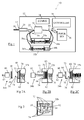
- Fig 1 is a schematic diagram of a media depository 10 (in the form of a combined banknote and cheque depository) according to one embodiment of the present invention.
- the combined depository 10 receives and stores both banknotes and cheques in one or more combined (mixed) media containers.
- the combined depository 10 includes a housing 12 defining an input aperture 14 for receiving a bunch 16 of media items.
- the combined depository 10 further comprises: a media item separator 20; a pivoting input transport 22; a discriminator 30; first and second combined media containers 32a,32b; a communications facility 34 for communicating with a terminal controller (not shown); a purge bin 36 for receiving media items that are unsuitable for deposit and not removed by the depositing customer; and a controller 38 for controlling the operation of the depository 10.
- the media item separator 20 is operable to separate a received bunch 16 of media items, and convey each separated media item onto the pivoting input transport 22 (when the pivoting input transport 22 is in the closed position).
- the pivoting input transport 22 conveys individual media items to the discriminator 30, which ascertains if a particular media item is a banknote, a cheque, or another type of document.
- the discriminator 30 includes a pair of imagers (not shown) for imaging both sides of a media item, and includes an algorithm (not shown) for validating banknotes, and for extracting data from cheques. Suitable discriminators are well known to those of skill in the art and are commercially available from a number of different vendors, so will not be described herein.
- the discriminator 30 conveys validation information (for example, banknote denomination, cheque amount, and the like) to the controller 38.
- a first path 40 links the discriminator 30 to either the purge bin 36 (when a diverter gate/escrow 42 is closed) or a first entrance loader 44a,b of one of the combined media containers 32a,32b (when the diverter gate/escrow 42 is open).
- this first transport path 40 is used to transport banknotes (referred to as the banknote transport path 40).
- the second path 50 links the discriminator 30 to a second entrance loader 54a,b (opposite the first entrance loader 44a,b) of the combined media containers 32a,32b when the pivoting input transport 22 is in the open position.
- this second transport path 50 is used to transport cheques (referred to as the cheque transport path 50).
- FIGs 2A to 2C are schematic front views of the second entrance loader 54b and the second container 32b.
- the first and second entrance loaders 44a,b and 54a,b are identical, so only one will be described in detail herein.
- Fig 2A illustrates the second entrance loader 54b in an inactive position but loaded with a cheque 58.
- Fig 2B illustrates the loader in an activated position, depositing the loaded cheque 58 into the second container 32b.
- Fig 2C illustrates the second entrance loader 54b returned to the inactive position after depositing the loaded cheque 58 into the second container 32b.
- the second entrance loader 54b comprises a motor 60 controlling a plunger 62 coupled to a media support 64. As shown in Fig 2A , when the plunger 62 is in the inactive position, the media support 64 can receive a cheque 58 conveyed via the cheque transport path 50.
- the second entrance 70 includes hinged flaps 72,74 that can be deflected inwards by the combination of the advancing media support 64 and the cheque 58.
- the second container 32b includes an urging mechanism 76 in the form of a resilient member (comprising a pair of coil springs) urging a moveable support 78 (in the form of a plate) against a horizontal stack of cheques 80 stored within the second container 32b, so that the stack of cheques 80 are in turn urged towards the second entrance 70.
- This causes the hinged flaps 72,74 to be deflected back to their rest position, as illustrated in Fig 2C .
- the cheque 58 becomes part of the stack 80 of cheques.
- a base 82 is provided within the container 32 for supporting the horizontal stack of cheques 80.
- the deflecting flaps 72,74 have a complementary profile to that of the media support 64 to allow the media support to pass through the deflecting flaps 72,74 when no cheque 58 is carried by the media support 64.
- Fig 4 is a schematic diagram illustrating a side view of the second container 32b.
- the second container 32b has a first entrance 170 (opposite, and corresponding to, second entrance 70), deflecting flaps 172,174 (opposite, and corresponding to, deflecting flaps 72,74), a banknote urging plate 178 (opposite, and corresponding to, cheque urging plate 78) for urging a horizontal stack of banknotes 180 stored within the second container 32b against the first entrance 170.
- the second container 32b includes a detector 84 in the form of a circuit that couples to the depository controller 38 when the second container 32b is installed in the depository housing 12.
- the circuit 84 communicates with a contact sensor 86 coupled to the cheque urging plate 78 and oriented towards the banknote urging plate 178.
- the circuit 84 changes state when the contact sensor 86 touches the banknote urging plate 178, thereby indicating to the depository controller 38 that the cheque urging plate 78 and the banknote urging plate 178 are within a predetermined distance of each other.
- the first and second containers 32a,b are inserted long side first (in contrast to conventional currency cassettes that are typically inserted short side first), but media items are loaded into the short sides of the first and second containers 32a,b (in contrast to currency hoppers that typically load media through an open top of the hopper).
- the first and second containers 32a,b include a removable lid (not shown) for allowing access to replenishers to the interior of the containers 32a,b.
- Fig 5 is a schematic diagram illustrating a self-service terminal 200 (in the form of an ATM) incorporating the combined banknote and cheque depository 10.
- the ATM 200 comprises a user interface 204 for receiving input (information and media) from, and providing output (information and media) to, a customer.
- the user interface 204 comprises: a moulded fascia 206 defining slots for accessing devices located within the ATM 200 and in registration with the slots; a display 208 aligned with opposing columns of function defined keys (FDKs) 210; an encrypting keypad 212; a token reader, in the form of a motorised card reader/writer (MCRW) device, located behind a card reader slot 214; a receipt printer located behind a receipt printer slot 216; a media dispenser 218, in the form of a cash dispenser, located behind a cash exit slot 220; and the combined banknote and cheque depository 10 located behind a depository slot 222.
- FDKs function defined keys
- MCRW motorised card reader/writer
- a customer inserts a card into the card reader slot 214, selects a deposit transaction using either the keypad 212 or an FDK 210, and then inserts a bunch of media items for deposit into depository slot 222.
- the depository 10 processes a deposited bunch of media items in a conventional manner, so this process will only be described very briefly herein.
- the media item separator 20 in the combined banknote and cheque depository 10 strips off individual media items from the deposited bunch, and conveys these one at a time, past the pivoting input transport 22 (which is in the closed position), to the discriminator 30.
- the discriminator 30 ascertains what the media item is, and whether it is genuine (if it is a banknote). If the media item cannot be ascertained, then it is sent to the diverter gate/escrow 42 for temporary storage while the rest of the media items in the deposited bunch are validated.
- the pivoting input transport 22 is moved to the open position, and the processed cheques are sent via the cheque transport path 50 to the second entrance loader 54 of either the first or second container 32a,b, depending on which container 32 is to be filled first.
- the diverter gate/escrow 42 is moved to (or maintained in) the open position to allow banknotes to be conveyed via the banknote transport path 40 to the first entrance loader 44 of either the first or second container 32a,b, depending on the denomination of banknote being conveyed.
- the diverter gate/escrow 42 is moved to (or maintained in) the open position to allow banknotes to be conveyed via the banknote transport path 40 to the first entrance loader 44 of either the first or second container 32a,b, depending on the denomination of banknote being conveyed.
- one container 32a will be used for one denomination
- another container 32b will be used for another denomination.
- Any media items that were not identified are reversed out of the diverter gate/escrow 42, through the discriminator 30 and returned to the customer via the depository slot 222 of the ATM 200. If not removed by the customer within a preset time period, the unidentified media items can be transported back to the purge bin 36.
- the urging plates 78,178 will gradually move closer together, compressing the coil springs 76, until the contact sensor 86 touches the banknote urging plate 178, triggering a state change in the circuit 84.
- This state change is communicated to the depository controller 38, which conveys a "container full" status message to an ATM controller (not shown) in the ATM 200.
- the depository 10 When one container (for example, 32a) is full, the depository 10 then conveys all further deposits to the remaining containers (for example, 32b) that are not yet full. Once all containers 32a,b are full, then the ATM 200 ceases to offer a deposit function to customers until the containers 32a,b have been emptied or replaced with empty containers 32.
- this embodiment has the advantage that the amount of storage space assigned to cheques and banknotes is automatic and dynamic.
- a different detector to the circuit 84 and contact sensor 86 may be provided.
- a potentiometer arrangement may be implemented by the urging plates sliding along a resistor, so that as the urging plates move closer to each other, the effective resistance of the resistor is lowered.
- Alternative electrical or mechanical detectors may be used, such as proximity detectors, strain gauges, and the like.
- the contact sensor 86 may be provided on arm extending from the plate 78 (or the plate 178); the length of the arm corresponding to the desired proximity of the two plates 78,178 that will trigger a container full condition.
- a plurality of contact sensors 86 may be provided on arms of different lengths, so that an early warning is provided that a container is nearing full storage capacity.
- the resilient member 76 may take a different form (such as a different number of coil springs, one or more leaf springs, a gas spring, a ratchet, or the like), or be located in a different part of the container, such as below the base 82.
- a different number of containers may be provided for receiving deposited media; for example, a greater or fewer number than two containers may be provided.
- Some containers may be provided to store counterfeit media in one part and suspect counterfeit media in the other part of the container.
- Some containers may store two denominations, one denomination in each of the two parts, so that the two denominations are segregated within one container.
- additional purge bins may be provided, for example, one for suspected counterfeit notes, and one for counterfeit notes.
- different media items may be deposited than cheques or banknotes, for example, passes, tickets, licences, or the like.
- the entrance loader may comprise a stacker wheel arrangement, or any other convenient media loading mechanism.
- the steps of the methods described herein may be carried out in any suitable order, or simultaneously where appropriate.
- the methods described herein may be performed by software in machine readable form on a tangible storage medium or as a propagating signal.
Landscapes
- Physics & Mathematics (AREA)
- General Physics & Mathematics (AREA)
- Pile Receivers (AREA)
- Separation, Sorting, Adjustment, Or Bending Of Sheets To Be Conveyed (AREA)
- Sheets, Magazines, And Separation Thereof (AREA)
Abstract
Description
- The present invention relates to a media depository.
- Media depositories are typically used in self-service terminals (SSTs), such as automated teller machines (ATMs) to receive and store media items deposited by customers. These media items include cheques, cash (banknotes and/or coins), and other items.
- The media items may be deposited either individually, or as a bunch of either cash or cheques, or as a mixed bunch of cash and cheques.
- ATM owners prefer to restrict the footprint of an ATM because an ATM is typically located in an area of high value per square metre, such as a retail outlet or a bank branch. This means that there is a practical limit to the number of deposit containers that can be provided in an ATM.
- It is desirable to segregate deposited cash and cheques by storing cash and cheques in different containers. However, it is difficult to predict the relative quantities of cash and cheques that will be deposited at any particular ATM. Each ATM only has a fixed, and relatively small, number of deposit containers. As a consequence, it is difficult to predict the number of deposit containers that should be allocated for cheques and the number of deposit containers that should be allocated for cash.
- Once one type of deposit container (for example, cheques) is full, then the ATM can no longer accept deposits of that type of media until a service person has visited the ATM and emptied the full container or containers. However, there is also a requirement to ensure that ATMs do not have to be serviced, replenished, or emptied (of deposited media, such as cash or cheques) too frequently.
- It would therefore be advantageous to provide an ATM having dynamic storage of cheques and cash during use of the ATM so that storage of cheques and cash can be optimised.
- Accordingly, the invention generally provides methods, systems, and apparatus for dynamic storage of different media types that require segregation.
- In addition to the Summary of Invention provided above and the subject matter disclosed below in the Detailed Description, the following paragraphs of this section are intended to provide further basis for alternative claim language for possible use during prosecution of this application, if required. If this application is granted, some aspects of the invention may relate to claims added during prosecution of this application, other aspects may relate to claims deleted during prosecution, other aspects may relate to subject matter never claimed. Furthermore, the various aspects detailed hereinafter are independent of each other, except where stated otherwise. Any claim corresponding to one aspect should not be construed as incorporating any element or feature of the other aspects unless explicitly stated in that claim.
- According to a first aspect there is provided a media depository comprising: an input for receiving deposited media items and for conveying the deposited media items, one at a time; a discriminator arranged to receive individual deposited media items from the input, and to ascertain whether each individual deposited media item is a first type of media item or a second type of media item; and a combined media container arranged to receive individual deposited media items from the discriminator, the combined media container comprising: a first media entrance arranged to receive a first type of media item; a second media entrance, located opposite the first media entrance, and arranged to receive a second type of media item, different from the first type; a first moveable support arranged to receive the first type of media items inserted through the first entrance; a second moveable support, located opposite the first moveable support, and arranged to receive the second type of media items inserted through the second entrance; an urging mechanism coupled to the first and second moveable supports and arranged to urge the first moveable support towards the first media entrance and the second moveable support towards the second media entrance, so that the first and second moveable supports are initially located at the first and second entrances respectively, and move closer to each other as media items are deposited.
- The first type of media item may be cheques.
- The second type of media item may be banknotes.
- The combined media container may be coupled to the discriminator by a first transport path arranged to transport cheques to the first media entrance, and coupled to the discriminator by a second transport path arranged to transport banknotes to the second media entrance.
- The moveable supports may comprise plates.
- Each of the first and second media entrances may further comprise one or more flaps which deflect inwards to allow media items to be inserted therethrough, but prevent media items from exiting through the entrances. The flaps may be hingeably coupled to the media entrances.
- The urging mechanism may comprise a resilient member coupled between the first and second moveable supports. The resilient member may comprise a coil spring, a gas spring, a leaf spring, or the like.
- The urging mechanism may comprise a plurality of resilient members coupled between the first and second moveable supports.
- The urging mechanism may comprise a ratchet mechanism.
- A detector may be provided to detect when the first and second moveable supports come within a predetermined distance of each other.
- The media depository may comprise a plurality of combined media containers, each combined media container storing two different types of media item. For example, eight different types of media item may be stored in four combined media containers.
- According to a second aspect there is provided a self-service terminal including the media depository of the first aspect.
- According to a third aspect there is provided a combined media container comprising: a storage chamber defining a first media entrance arranged to receive a first type of media item, and a second media entrance, located opposite the first media entrance, and arranged to receive a second type of media item, different from the first type of media item; a first moveable support located within the storage chamber and arranged to receive the first type of media items inserted through the first entrance; a second moveable support located within the storage chamber and opposite the first moveable support, and arranged to receive the second type of media items inserted through the second entrance; an urging mechanism coupled to the first and second moveable supports and arranged to urge the first moveable support towards the first media entrance and the second moveable support towards the second media entrance, so that the first and second moveable supports are initially located at the first and second entrances respectively, and move closer to each other as media items are deposited therein.
- According to a fourth aspect there is provided a method of storing two different types of media item in a container, the method comprising: receiving a first type of media item; conveying the first type of media item to a first entrance at a first side of a container; urging a first moveable support within the container further away from the first entrance by loading the first type of media item into the first side of the container; receiving a second type of media item; conveying the second type of media item to a second entrance at a second side of a container, opposite the first side; urging a second moveable support within the container further away from the second entrance, and towards the first entrance, by loading the second type of media item into the second side of the container; and detecting when the first and second moveable supports come within a predetermined distance of each other.
- The method may comprise the further step of alerting a depository incorporating the container in response to detecting when the first and second moveable supports come within a predetermined distance of each other.
- By virtue of these aspects of the invention, a combined media container is provided that can be filled with cheques (or another type of media item) from one side and with banknotes (or another type of media item) from the opposite side. The two different types of media items (for example, cheques and banknotes) are segregated by moveable supports that are forced back as new media items are inserted. The combined media container is full when the two moveable supports come within a predetermined distance of each other (which may be physical contact, that is, zero distance).
- The adjectives "first" and "second" are used herein to denote entrances, paths, containers, and the like. These terms are provided merely to distinguish one element from another element and should not be interpreted as implying any precedence or priority of one element (for example, a first entrance) over another element (for example, a second entrance).
- These and other aspects will be apparent from the following specific description, given by way of example, with reference to the accompanying drawings.
-
Fig 1 is a schematic diagram of a media depository according to one embodiment of the present invention; -
Figs 2A to 2C are schematic front views of parts (an entrance loader and its associated combined media container) of the media depository ofFig 1 ; -
Fig 3 is a schematic side view of the entrance loader ofFig 2 aligned with its associated combined media container of the media depository ofFig 1 ; -
Fig 4 is a schematic diagram illustrating the combined media container ofFigs 2A to 2C in more detail; and -
Fig 5 is a pictorial diagram illustrating a self-service terminal incorporating the media depository ofFig 1 . - Reference is first made to
Fig 1 , which is a schematic diagram of a media depository 10 (in the form of a combined banknote and cheque depository) according to one embodiment of the present invention. The combineddepository 10 receives and stores both banknotes and cheques in one or more combined (mixed) media containers. - The combined
depository 10 includes ahousing 12 defining aninput aperture 14 for receiving abunch 16 of media items. The combineddepository 10 further comprises: amedia item separator 20; apivoting input transport 22; adiscriminator 30; first and second combinedmedia containers communications facility 34 for communicating with a terminal controller (not shown); apurge bin 36 for receiving media items that are unsuitable for deposit and not removed by the depositing customer; and acontroller 38 for controlling the operation of thedepository 10. - The
media item separator 20 is operable to separate a receivedbunch 16 of media items, and convey each separated media item onto the pivoting input transport 22 (when thepivoting input transport 22 is in the closed position). - The
pivoting input transport 22 conveys individual media items to thediscriminator 30, which ascertains if a particular media item is a banknote, a cheque, or another type of document. Thediscriminator 30 includes a pair of imagers (not shown) for imaging both sides of a media item, and includes an algorithm (not shown) for validating banknotes, and for extracting data from cheques. Suitable discriminators are well known to those of skill in the art and are commercially available from a number of different vendors, so will not be described herein. Thediscriminator 30 conveys validation information (for example, banknote denomination, cheque amount, and the like) to thecontroller 38. - There are two media transport paths out of the
discriminator 30. - A
first path 40 links thediscriminator 30 to either the purge bin 36 (when a diverter gate/escrow 42 is closed) or afirst entrance loader 44a,b of one of the combinedmedia containers escrow 42 is open). In this embodiment, thisfirst transport path 40 is used to transport banknotes (referred to as the banknote transport path 40). - The
second path 50 links thediscriminator 30 to asecond entrance loader 54a,b (opposite thefirst entrance loader 44a,b) of the combinedmedia containers pivoting input transport 22 is in the open position. In this embodiment, thissecond transport path 50 is used to transport cheques (referred to as the cheque transport path 50). - Reference will now also be made to
Figs 2A to 2C , which are schematic front views of thesecond entrance loader 54b and thesecond container 32b. The first andsecond entrance loaders 44a,b and 54a,b are identical, so only one will be described in detail herein. -
Fig 2A illustrates thesecond entrance loader 54b in an inactive position but loaded with acheque 58.Fig 2B illustrates the loader in an activated position, depositing theloaded cheque 58 into thesecond container 32b.Fig 2C illustrates thesecond entrance loader 54b returned to the inactive position after depositing the loadedcheque 58 into thesecond container 32b. - The
second entrance loader 54b comprises amotor 60 controlling aplunger 62 coupled to amedia support 64. As shown inFig 2A , when theplunger 62 is in the inactive position, themedia support 64 can receive acheque 58 conveyed via thecheque transport path 50. - When the motor is activated, the
plunger 62 advances towards thesecond container 32b, as shown inFig 2B . Thesecond entrance 70 includes hingedflaps media support 64 and thecheque 58. - The
second container 32b includes anurging mechanism 76 in the form of a resilient member (comprising a pair of coil springs) urging a moveable support 78 (in the form of a plate) against a horizontal stack ofcheques 80 stored within thesecond container 32b, so that the stack ofcheques 80 are in turn urged towards thesecond entrance 70. This causes the hinged flaps 72,74 to be deflected back to their rest position, as illustrated inFig 2C . Once thecheque 58 has been deposited into thesecond container 32b by thesecond entrance loader 54b, thecheque 58 becomes part of thestack 80 of cheques. Abase 82 is provided within the container 32 for supporting the horizontal stack ofcheques 80. - As best seen in
Fig 3 , the deflecting flaps 72,74 have a complementary profile to that of themedia support 64 to allow the media support to pass through the deflecting flaps 72,74 when nocheque 58 is carried by themedia support 64. - Reference will now be made to
Fig 4 , which is a schematic diagram illustrating a side view of thesecond container 32b. Thesecond container 32b has a first entrance 170 (opposite, and corresponding to, second entrance 70), deflecting flaps 172,174 (opposite, and corresponding to, deflecting flaps 72,74), a banknote urging plate 178 (opposite, and corresponding to, cheque urging plate 78) for urging a horizontal stack ofbanknotes 180 stored within thesecond container 32b against thefirst entrance 170. - The
second container 32b includes adetector 84 in the form of a circuit that couples to thedepository controller 38 when thesecond container 32b is installed in thedepository housing 12. Thecircuit 84 communicates with acontact sensor 86 coupled to thecheque urging plate 78 and oriented towards thebanknote urging plate 178. Thecircuit 84 changes state when thecontact sensor 86 touches thebanknote urging plate 178, thereby indicating to thedepository controller 38 that thecheque urging plate 78 and thebanknote urging plate 178 are within a predetermined distance of each other. - In this embodiment, the first and
second containers 32a,b are inserted long side first (in contrast to conventional currency cassettes that are typically inserted short side first), but media items are loaded into the short sides of the first andsecond containers 32a,b (in contrast to currency hoppers that typically load media through an open top of the hopper). - In this embodiment, the first and
second containers 32a,b include a removable lid (not shown) for allowing access to replenishers to the interior of thecontainers 32a,b. - Reference will now be made to
Fig 5 , which is a schematic diagram illustrating a self-service terminal 200 (in the form of an ATM) incorporating the combined banknote andcheque depository 10. - The
ATM 200 comprises auser interface 204 for receiving input (information and media) from, and providing output (information and media) to, a customer. - The
user interface 204 comprises: amoulded fascia 206 defining slots for accessing devices located within theATM 200 and in registration with the slots; adisplay 208 aligned with opposing columns of function defined keys (FDKs) 210; an encryptingkeypad 212; a token reader, in the form of a motorised card reader/writer (MCRW) device, located behind acard reader slot 214; a receipt printer located behind areceipt printer slot 216; amedia dispenser 218, in the form of a cash dispenser, located behind acash exit slot 220; and the combined banknote andcheque depository 10 located behind adepository slot 222. - In use, a customer inserts a card into the
card reader slot 214, selects a deposit transaction using either thekeypad 212 or anFDK 210, and then inserts a bunch of media items for deposit intodepository slot 222. - The depository 10 processes a deposited bunch of media items in a conventional manner, so this process will only be described very briefly herein.
- The
media item separator 20 in the combined banknote andcheque depository 10 strips off individual media items from the deposited bunch, and conveys these one at a time, past the pivoting input transport 22 (which is in the closed position), to thediscriminator 30. - The
discriminator 30 ascertains what the media item is, and whether it is genuine (if it is a banknote). If the media item cannot be ascertained, then it is sent to the diverter gate/escrow 42 for temporary storage while the rest of the media items in the deposited bunch are validated. - When cheques have been processed, the pivoting
input transport 22 is moved to the open position, and the processed cheques are sent via thecheque transport path 50 to the second entrance loader 54 of either the first orsecond container 32a,b, depending on which container 32 is to be filled first. - When banknotes have been processed, the diverter gate/
escrow 42 is moved to (or maintained in) the open position to allow banknotes to be conveyed via thebanknote transport path 40 to the first entrance loader 44 of either the first orsecond container 32a,b, depending on the denomination of banknote being conveyed. Typically, onecontainer 32a will be used for one denomination, and anothercontainer 32b will be used for another denomination. - Any media items that were not identified are reversed out of the diverter gate/
escrow 42, through thediscriminator 30 and returned to the customer via thedepository slot 222 of theATM 200. If not removed by the customer within a preset time period, the unidentified media items can be transported back to thepurge bin 36. - As each container 32 fills up from each side, the urging plates 78,178 will gradually move closer together, compressing the coil springs 76, until the
contact sensor 86 touches thebanknote urging plate 178, triggering a state change in thecircuit 84. This state change is communicated to thedepository controller 38, which conveys a "container full" status message to an ATM controller (not shown) in theATM 200. - When one container (for example, 32a) is full, the
depository 10 then conveys all further deposits to the remaining containers (for example, 32b) that are not yet full. Once allcontainers 32a,b are full, then theATM 200 ceases to offer a deposit function to customers until thecontainers 32a,b have been emptied or replaced with empty containers 32. - It will now be appreciated that this embodiment has the advantage that the amount of storage space assigned to cheques and banknotes is automatic and dynamic.
- Various modifications may be made to the above described embodiment within the scope of the invention, for example, in other embodiments, a different detector to the
circuit 84 andcontact sensor 86 may be provided. For example, a potentiometer arrangement may be implemented by the urging plates sliding along a resistor, so that as the urging plates move closer to each other, the effective resistance of the resistor is lowered. Alternative electrical or mechanical detectors may be used, such as proximity detectors, strain gauges, and the like. - In other embodiments, the
contact sensor 86 may be provided on arm extending from the plate 78 (or the plate 178); the length of the arm corresponding to the desired proximity of the two plates 78,178 that will trigger a container full condition. - In other embodiments a plurality of
contact sensors 86 may be provided on arms of different lengths, so that an early warning is provided that a container is nearing full storage capacity. - In other embodiments, the
resilient member 76 may take a different form (such as a different number of coil springs, one or more leaf springs, a gas spring, a ratchet, or the like), or be located in a different part of the container, such as below thebase 82. - In other embodiments, a different number of containers may be provided for receiving deposited media; for example, a greater or fewer number than two containers may be provided. Some containers may be provided to store counterfeit media in one part and suspect counterfeit media in the other part of the container. Some containers may store two denominations, one denomination in each of the two parts, so that the two denominations are segregated within one container.
- In other embodiments, additional purge bins may be provided, for example, one for suspected counterfeit notes, and one for counterfeit notes.
- In other embodiments, different media items may be deposited than cheques or banknotes, for example, passes, tickets, licences, or the like.
- In other embodiments, a different type of entrance loader may be used to that described above, for example, the entrance loader may comprise a stacker wheel arrangement, or any other convenient media loading mechanism.
- The steps of the methods described herein may be carried out in any suitable order, or simultaneously where appropriate. The methods described herein may be performed by software in machine readable form on a tangible storage medium or as a propagating signal.
- The terms "comprising", "including", "incorporating", and "having" are used herein to recite an open-ended list of one or more elements or steps, not a closed list. When such terms are used, those elements or steps recited in the list are not exclusive of other elements or steps that may be added to the list.
- Unless otherwise indicated by the context, the terms "a" and "an" are used herein to denote at least one of the elements, integers, steps, features, operations, or components mentioned thereafter, but do not exclude additional elements, integers, steps, features, operations, or components.
Claims (15)
- A media depository (10) comprising:an input (14) for receiving deposited media items (16) and for conveying the deposited media items (16), one at a time;a discriminator (30) arranged to receive individual deposited media items from the input (14), and to ascertain whether each individual deposited media item is a first type of media item (58) or a second type of media item (180); anda combined media container (32) arranged to receive individual deposited media items from the discriminator (30),the combined media container (32) comprising:a first media entrance (70) arranged to receive the first type of media item (58);a second media entrance (170), located opposite the first media entrance (70), and arranged to receive the second type of media item (180), different from the first type (58);a first moveable support (78) arranged to receive the first type of media items (58) inserted through the first entrance (70);a second moveable support (178), located opposite the first moveable support (78), and arranged to receive the second type of media items (180) inserted through the second entrance (170);an urging mechanism (76) coupled to the first and second moveable supports (78,178) and arranged to urge the first moveable support (78) towards the first media entrance (70) and the second moveable support (178) towards the second media entrance (170), so that the first and second moveable supports (78,178) are initially located at the first and second entrances (70,170) respectively, and move closer to each other as media items are deposited.
- A media depository according to claim 1, wherein the first type of media item (58) comprises cheques.
- A media depository according to claim 1 or 2, wherein the second type of media item (180) comprises banknotes.
- A media depository (10) according to any preceding claim, wherein the combined media container (32) is coupled to the discriminator (30) by a cheque transport path (50) arranged to transport cheques (58) to the first media entrance (70), and coupled to the discriminator (30) by a banknote transport path (40) arranged to transport banknotes to the second media entrance (170).
- A media depository (10) according to any preceding claim, wherein the moveable supports (78) comprise plates.
- A media depository (10) according to any preceding claim, wherein each of the first and second media entrances (70,170) further comprises one or more flaps (72,74;172,174) which deflect inwards to allow media items (58,180) to be inserted therethrough, but prevent media items (58,180) from exiting therethrough.
- A media depository (10) according to claim 6, wherein the flaps (72,74;172,174) are hingeably coupled to the media entrances (70,170).
- A media depository (10) according to any preceding claim, wherein the urging mechanism (76) comprises a resilient member coupled between the first and second moveable supports (78,178).
- A media depository (10) according to claim 8, wherein the resilient member comprises a coil spring.
- A media depository (10) according to any preceding claim, further comprising a detector (84) arranged to detect when the first and second moveable supports (78,178) are within a predetermined distance of each other.
- A media depository (10) according to claim 10, wherein the detector (84) comprises a contact sensor coupled to the first moveable support (78), and an associated circuit for changing state when the contact sensor touches the second moveable support (178).
- A self-service terminal (200) including the media depository (10) of claim 1.
- A combined media container (32) comprising:a storage chamber defining a first media entrance (70) arranged to receive a first type of media item (58), and a second media entrance (170), located opposite the first media entrance (70), and arranged to receive a second type of media item (180), different from the first type of media item (58);a first moveable support (78) located within the storage chamber and arranged to receive the first type of media items (58) inserted through the first entrance (70);a second moveable support (170) located within the storage chamber and opposite the first moveable support (70), and arranged to receive the second type of media items (180) inserted through the second entrance (170);an urging mechanism (76) coupled to the first and second moveable supports (78,178) and arranged to urge the first moveable support (78) towards the first media entrance (70) and the second moveable support (178) towards the second media entrance (170), so that the first and second moveable supports (78,178) are initially located at the first and second entrances (70,170) respectively, and move closer to each other as media items (58,180) are deposited therein.
- A media container (32) according to claim 13, wherein the media container (32) further comprises a detector (84) arranged to detect when the first and second moveable supports (78,178) are within a predetermined distance of each other.
- A method of storing two different types of media item in a container, the method comprising:receiving a first type of media item;conveying the first type of media item to a first entrance at a first side of a container;urging a first moveable support within the container further away from the first entrance by loading the first type of media item into the first side of the container;receiving a second type of media item;conveying the second type of media item to a second entrance at a second side of a container, opposite the first side;urging a second moveable support within the container further away from the second entrance, and towards the first entrance, by loading the second type of media item into the second side of the container; anddetecting when the first and second moveable supports are within a predetermined distance of each other.
Applications Claiming Priority (1)
| Application Number | Priority Date | Filing Date | Title |
|---|---|---|---|
| US12/551,129 US8573405B2 (en) | 2009-08-31 | 2009-08-31 | Media depository |
Publications (3)
| Publication Number | Publication Date |
|---|---|
| EP2290623A2 true EP2290623A2 (en) | 2011-03-02 |
| EP2290623A3 EP2290623A3 (en) | 2011-11-09 |
| EP2290623B1 EP2290623B1 (en) | 2012-11-14 |
Family
ID=43244840
Family Applications (1)
| Application Number | Title | Priority Date | Filing Date |
|---|---|---|---|
| EP10172271A Active EP2290623B1 (en) | 2009-08-31 | 2010-08-09 | Media depository |
Country Status (3)
| Country | Link |
|---|---|
| US (1) | US8573405B2 (en) |
| EP (1) | EP2290623B1 (en) |
| ES (1) | ES2396442T3 (en) |
Cited By (1)
| Publication number | Priority date | Publication date | Assignee | Title |
|---|---|---|---|---|
| WO2015014977A1 (en) * | 2013-08-01 | 2015-02-05 | Ci Tech Components Ag | Container for documents of value |
Families Citing this family (5)
| Publication number | Priority date | Publication date | Assignee | Title |
|---|---|---|---|---|
| JP2012206497A (en) | 2011-03-15 | 2012-10-25 | Seiko Epson Corp | Multifunction printing device |
| JP2013020331A (en) * | 2011-07-08 | 2013-01-31 | Seiko Epson Corp | Medium processor |
| JP2013056491A (en) | 2011-09-09 | 2013-03-28 | Seiko Epson Corp | Media processing device |
| EP3567559A1 (en) * | 2018-05-07 | 2019-11-13 | Wincor Nixdorf International GmbH | Value note cassette |
| JP2022141119A (en) * | 2021-03-15 | 2022-09-29 | グローリー株式会社 | Currency processing device |
Family Cites Families (53)
| Publication number | Priority date | Publication date | Assignee | Title |
|---|---|---|---|---|
| US2602386A (en) * | 1949-07-28 | 1952-07-08 | Roger L Brigham | Cut film adapter for serial photography for photographic cameras |
| US2841275A (en) * | 1955-06-16 | 1958-07-01 | Schwimmer David | Combination dispensing and disposal device |
| US3095087A (en) * | 1960-01-12 | 1963-06-25 | Sam M Yates | Combination tissue dispensing and disposal container |
| US3331498A (en) * | 1966-06-29 | 1967-07-18 | Leone Baxter | Tissue dispensing and disposal device |
| JPS5574680A (en) * | 1978-11-30 | 1980-06-05 | Tokyo Shibaura Electric Co | Paper item treatment unit |
| JPS5963772U (en) * | 1982-10-14 | 1984-04-26 | 株式会社東芝 | Paper sheet processing equipment |
| US4726474A (en) * | 1984-05-08 | 1988-02-23 | Laurel Bank Machines Co., Ltd. | Circulating-type bill depositing and disbursing machine |
| GB2182717B (en) | 1985-11-12 | 1989-12-06 | Ncr Co | A container and method for loading currency notes into a currency cassette |
| US5000322A (en) * | 1988-05-31 | 1991-03-19 | Laurel Bank Machines Co., Ltd. | Bill receiving and dispensing machine |
| US4879442A (en) * | 1988-08-22 | 1989-11-07 | Giovine Robert L | Tissue container and waste tissue receptacle |
| US5129545A (en) * | 1990-05-29 | 1992-07-14 | Parks Lance K | Container for dispensing and disposing of tissues |
| DE4408981C1 (en) * | 1994-03-16 | 1995-06-22 | Siemens Nixdorf Inf Syst | Output unit for coupons with box-shaped coupon container |
| US5836436A (en) * | 1996-04-15 | 1998-11-17 | Mantissa Corporation | Tilting cart for a package sorting conveyor |
| US5984177A (en) * | 1996-08-16 | 1999-11-16 | Transaction Technology, Inc. | Multiple configuration automatic teller machine |
| JP3763641B2 (en) * | 1997-07-02 | 2006-04-05 | 富士通株式会社 | Page turning device |
| DE19706128A1 (en) * | 1997-02-17 | 1998-08-27 | Siemens Nixdorf Inf Syst | Storage cassette for ATMs |
| GB9707243D0 (en) * | 1997-04-09 | 1997-05-28 | Ncr Int Inc | Self-service deposit method and apparatus |
| KR100354531B1 (en) * | 1998-05-06 | 2005-12-21 | 삼성전자 주식회사 | Lossless Coding and Decoding System for Real-Time Decoding |
| US7883005B2 (en) * | 1998-11-25 | 2011-02-08 | Diebold, Incorporated | Banking system controlled by data bearing records |
| US6761308B1 (en) * | 1998-11-25 | 2004-07-13 | Diebold, Incorporated | Automated merchant banking apparatus and method |
| US7677442B2 (en) * | 1999-11-30 | 2010-03-16 | Diebold, Incorporated | Check accepting and cash dispensing automated banking machine system and method |
| US6474548B1 (en) * | 1999-11-30 | 2002-11-05 | Diebold, Incorporated | Deposit accepting and storage apparatus and method for automated banking machine |
| US8181853B2 (en) * | 1999-11-30 | 2012-05-22 | Diebold Self-Service Systems Division Of Diebold, Incorporated | System controlled by data bearing records including check accepting and cash dispensing automated banking machine |
| GB2363890A (en) * | 2000-06-24 | 2002-01-09 | Ncr Int Inc | Self service terminal with a media entry aperture of variable size |
| DE10051554A1 (en) * | 2000-10-18 | 2002-05-02 | Giesecke & Devrient Gmbh | Device and method for depositing banknotes |
| GB0026022D0 (en) | 2000-10-24 | 2000-12-13 | Rue De Int Ltd | Document store acceptor and recirculator |
| DE10101565C1 (en) * | 2001-01-15 | 2001-12-06 | Wincor Nixdorf Gmbh & Co Kg | Output unit for the output of single sheets |
| GB0107689D0 (en) * | 2001-03-28 | 2001-05-16 | Ncr Int Inc | Self service terminal |
| US6863192B2 (en) * | 2002-04-29 | 2005-03-08 | Larry Neal Tumlinson | Expandable, combination dispenser and disposal for tissues |
| JP2004102626A (en) * | 2002-09-09 | 2004-04-02 | Asahi Seiko Kk | Storage device drive of bill receiving and storing device |
| US7922076B2 (en) * | 2006-07-27 | 2011-04-12 | Diebold Self-Service Systems | Banking apparatus operated responsive to data bearing records |
| US6945456B2 (en) * | 2002-11-25 | 2005-09-20 | Diebold Self-Service Systems A Division Of Diebold, Incorporated | Automated banking machine including temperature controlled housing |
| RU2304308C2 (en) * | 2002-12-19 | 2007-08-10 | Дайболд, Инкорпорейтед | Automatic teller machine for dispensing money with devices for lighting user interface |
| RU2299466C2 (en) * | 2002-12-31 | 2007-05-20 | Дайболд, Инкорпорейтед | Banknote cartridge for use with atm |
| GB2398914B (en) * | 2003-02-27 | 2006-07-19 | Ncr Int Inc | Module for validating deposited media |
| JP4200047B2 (en) * | 2003-05-30 | 2008-12-24 | 日立オムロンターミナルソリューションズ株式会社 | Automatic handling equipment for banknotes and securities |
| JP2005010967A (en) | 2003-06-18 | 2005-01-13 | Hitachi Ltd | Banknote deposit and withdrawal device and automatic cash transaction device |
| CN1813479A (en) * | 2003-06-30 | 2006-08-02 | 皇家飞利浦电子股份有限公司 | Video coding in an overcomplete wavelet domain |
| TW200601300A (en) * | 2003-06-30 | 2006-01-01 | Matsushita Electric Industrial Co Ltd | Apparatus and computer-readable program for generating volume image |
| US20050192705A1 (en) * | 2003-07-01 | 2005-09-01 | Asteres Inc. | Random access and random load dispensing unit |
| US7856401B2 (en) * | 2003-07-11 | 2010-12-21 | Ncr Corporation | Self-service terminal |
| US7175077B2 (en) * | 2005-03-09 | 2007-02-13 | Diebold Self-Services Systems Division Of Diebold, Incorporated | Check accepting and cash dispensing automated banking machine system and method |
| JP4713231B2 (en) * | 2005-06-15 | 2011-06-29 | 日立オムロンターミナルソリューションズ株式会社 | Banknote handling equipment |
| US7296735B2 (en) * | 2005-12-16 | 2007-11-20 | Ncr Corporation | Media thickness sensor assembly |
| US7793831B2 (en) * | 2006-11-10 | 2010-09-14 | Diebold Self-Service Systems, Division Of Diebold, Incorporated | Card activated automated banking machine |
| US7607573B1 (en) * | 2007-01-03 | 2009-10-27 | Diebold, Incorporated | Banking system operated responsive to data bearing records |
| US20100126915A1 (en) * | 2007-01-22 | 2010-05-27 | Glory Ltd | Banknote handling apparatus |
| US8336715B2 (en) * | 2007-02-08 | 2012-12-25 | Glory Ltd. | Banknote processing device |
| CN101925932B (en) * | 2008-01-25 | 2013-04-10 | 环球娱乐株式会社 | Banknote processing device and authentication determining and processing method |
| US20090229950A1 (en) * | 2008-03-14 | 2009-09-17 | Glory Ltd. | Verification system and banknote-and-coin handling system |
| JP4673393B2 (en) * | 2008-06-05 | 2011-04-20 | 日立オムロンターミナルソリューションズ株式会社 | Paper sheet handling apparatus and method |
| WO2010067421A1 (en) * | 2008-12-09 | 2010-06-17 | グローリー株式会社 | Paper currency receiving-treating apparatus, and paper currency receiving-treating method |
| US8256624B2 (en) * | 2009-03-25 | 2012-09-04 | Glory Ltd. | Money handling apparatus and dispensing method thereof |
-
2009
- 2009-08-31 US US12/551,129 patent/US8573405B2/en active Active
-
2010
- 2010-08-09 EP EP10172271A patent/EP2290623B1/en active Active
- 2010-08-09 ES ES10172271T patent/ES2396442T3/en active Active
Non-Patent Citations (1)
| Title |
|---|
| None |
Cited By (2)
| Publication number | Priority date | Publication date | Assignee | Title |
|---|---|---|---|---|
| WO2015014977A1 (en) * | 2013-08-01 | 2015-02-05 | Ci Tech Components Ag | Container for documents of value |
| EP2850600A1 (en) * | 2013-08-01 | 2015-03-25 | CI Tech Components AG | Container for documents of value |
Also Published As
| Publication number | Publication date |
|---|---|
| US20110049020A1 (en) | 2011-03-03 |
| US8573405B2 (en) | 2013-11-05 |
| EP2290623A3 (en) | 2011-11-09 |
| ES2396442T3 (en) | 2013-02-21 |
| EP2290623B1 (en) | 2012-11-14 |
Similar Documents
| Publication | Publication Date | Title |
|---|---|---|
| EP2062230B1 (en) | A coin dispensing apparatus and a coin deposit and dispensing apparatus | |
| KR101894267B1 (en) | Cash dispenser with escrow | |
| US20020003163A1 (en) | Self-service terminal | |
| EP1028399A1 (en) | Replenishment arrangements for automated teller machines | |
| US20100198396A1 (en) | Apparatus and method for depositing and/or dispensing at least banknotes having a first denomination and banknotes having a second denomination | |
| US20090260948A1 (en) | Money handling machine | |
| EP2290623B1 (en) | Media depository | |
| CN104517349B (en) | Banknote processing device | |
| US20170124813A1 (en) | System and Method for Processing Coin Deposits and Withdrawals in an Automated Banking Machine | |
| EP1131795B1 (en) | Self-service bank-terminal | |
| US8967362B2 (en) | Apparatus, method, software and graphical interface for flexible dispensing of coins in a coin handling apparatus | |
| EP0734001A2 (en) | Automated depository | |
| JP5277757B2 (en) | Banknote handling equipment | |
| JP3120397B2 (en) | Automatic transaction equipment | |
| JP2718808B2 (en) | Automatic transaction equipment | |
| JP3215373B2 (en) | Automatic trading system | |
| EP3764328B1 (en) | Device for handling notes of value and method for operating a device for handling notes of value | |
| JP3328522B2 (en) | Automatic transaction equipment | |
| JP7484617B2 (en) | Cash handling equipment | |
| US20210174627A1 (en) | Methods to Reduce Jamming in a Drum Style Bill Handler and Recycler | |
| JP2908544B2 (en) | A method for determining the amount of replenishment bills for automatic transaction devices and deposit / withdrawal devices | |
| JPH05162866A (en) | Banknote processing device with batch transfer function | |
| JPH10283525A (en) | Bank note receiving and paying device | |
| JPH0586586B2 (en) | ||
| JPH03148793A (en) | Cash transaction device |
Legal Events
| Date | Code | Title | Description |
|---|---|---|---|
| PUAI | Public reference made under article 153(3) epc to a published international application that has entered the european phase |
Free format text: ORIGINAL CODE: 0009012 |
|
| AK | Designated contracting states |
Kind code of ref document: A2 Designated state(s): AL AT BE BG CH CY CZ DE DK EE ES FI FR GB GR HR HU IE IS IT LI LT LU LV MC MK MT NL NO PL PT RO SE SI SK SM TR |
|
| AX | Request for extension of the european patent |
Extension state: BA ME RS |
|
| PUAL | Search report despatched |
Free format text: ORIGINAL CODE: 0009013 |
|
| AK | Designated contracting states |
Kind code of ref document: A3 Designated state(s): AL AT BE BG CH CY CZ DE DK EE ES FI FR GB GR HR HU IE IS IT LI LT LU LV MC MK MT NL NO PL PT RO SE SI SK SM TR |
|
| AX | Request for extension of the european patent |
Extension state: BA ME RS |
|
| RIC1 | Information provided on ipc code assigned before grant |
Ipc: G07D 11/00 20060101AFI20111004BHEP |
|
| 17P | Request for examination filed |
Effective date: 20120509 |
|
| GRAP | Despatch of communication of intention to grant a patent |
Free format text: ORIGINAL CODE: EPIDOSNIGR1 |
|
| GRAS | Grant fee paid |
Free format text: ORIGINAL CODE: EPIDOSNIGR3 |
|
| GRAA | (expected) grant |
Free format text: ORIGINAL CODE: 0009210 |
|
| AK | Designated contracting states |
Kind code of ref document: B1 Designated state(s): AL AT BE BG CH CY CZ DE DK EE ES FI FR GB GR HR HU IE IS IT LI LT LU LV MC MK MT NL NO PL PT RO SE SI SK SM TR |
|
| REG | Reference to a national code |
Ref country code: GB Ref legal event code: FG4D |
|
| REG | Reference to a national code |
Ref country code: CH Ref legal event code: EP Ref country code: AT Ref legal event code: REF Ref document number: 584333 Country of ref document: AT Kind code of ref document: T Effective date: 20121115 |
|
| REG | Reference to a national code |
Ref country code: GB Ref legal event code: 746 Effective date: 20121120 |
|
| REG | Reference to a national code |
Ref country code: IE Ref legal event code: FG4D |
|
| REG | Reference to a national code |
Ref country code: DE Ref legal event code: R084 Ref document number: 602010003588 Country of ref document: DE Effective date: 20121031 Ref country code: DE Ref legal event code: R096 Ref document number: 602010003588 Country of ref document: DE Effective date: 20130110 |
|
| REG | Reference to a national code |
Ref country code: ES Ref legal event code: GC2A Effective date: 20130129 |
|
| REG | Reference to a national code |
Ref country code: ES Ref legal event code: FG2A Ref document number: 2396442 Country of ref document: ES Kind code of ref document: T3 Effective date: 20130221 |
|
| REG | Reference to a national code |
Ref country code: NL Ref legal event code: VDEP Effective date: 20121114 |
|
| REG | Reference to a national code |
Ref country code: AT Ref legal event code: MK05 Ref document number: 584333 Country of ref document: AT Kind code of ref document: T Effective date: 20121114 |
|
| REG | Reference to a national code |
Ref country code: LT Ref legal event code: MG4D |
|
| PG25 | Lapsed in a contracting state [announced via postgrant information from national office to epo] |
Ref country code: FI Free format text: LAPSE BECAUSE OF FAILURE TO SUBMIT A TRANSLATION OF THE DESCRIPTION OR TO PAY THE FEE WITHIN THE PRESCRIBED TIME-LIMIT Effective date: 20121114 Ref country code: NO Free format text: LAPSE BECAUSE OF FAILURE TO SUBMIT A TRANSLATION OF THE DESCRIPTION OR TO PAY THE FEE WITHIN THE PRESCRIBED TIME-LIMIT Effective date: 20130214 Ref country code: SE Free format text: LAPSE BECAUSE OF FAILURE TO SUBMIT A TRANSLATION OF THE DESCRIPTION OR TO PAY THE FEE WITHIN THE PRESCRIBED TIME-LIMIT Effective date: 20121114 Ref country code: LT Free format text: LAPSE BECAUSE OF FAILURE TO SUBMIT A TRANSLATION OF THE DESCRIPTION OR TO PAY THE FEE WITHIN THE PRESCRIBED TIME-LIMIT Effective date: 20121114 Ref country code: HR Free format text: LAPSE BECAUSE OF FAILURE TO SUBMIT A TRANSLATION OF THE DESCRIPTION OR TO PAY THE FEE WITHIN THE PRESCRIBED TIME-LIMIT Effective date: 20121114 |
|
| PG25 | Lapsed in a contracting state [announced via postgrant information from national office to epo] |
Ref country code: SI Free format text: LAPSE BECAUSE OF FAILURE TO SUBMIT A TRANSLATION OF THE DESCRIPTION OR TO PAY THE FEE WITHIN THE PRESCRIBED TIME-LIMIT Effective date: 20121114 Ref country code: LV Free format text: LAPSE BECAUSE OF FAILURE TO SUBMIT A TRANSLATION OF THE DESCRIPTION OR TO PAY THE FEE WITHIN THE PRESCRIBED TIME-LIMIT Effective date: 20121114 Ref country code: PT Free format text: LAPSE BECAUSE OF FAILURE TO SUBMIT A TRANSLATION OF THE DESCRIPTION OR TO PAY THE FEE WITHIN THE PRESCRIBED TIME-LIMIT Effective date: 20130314 Ref country code: GR Free format text: LAPSE BECAUSE OF FAILURE TO SUBMIT A TRANSLATION OF THE DESCRIPTION OR TO PAY THE FEE WITHIN THE PRESCRIBED TIME-LIMIT Effective date: 20130215 Ref country code: BE Free format text: LAPSE BECAUSE OF FAILURE TO SUBMIT A TRANSLATION OF THE DESCRIPTION OR TO PAY THE FEE WITHIN THE PRESCRIBED TIME-LIMIT Effective date: 20121114 Ref country code: PL Free format text: LAPSE BECAUSE OF FAILURE TO SUBMIT A TRANSLATION OF THE DESCRIPTION OR TO PAY THE FEE WITHIN THE PRESCRIBED TIME-LIMIT Effective date: 20121114 |
|
| PG25 | Lapsed in a contracting state [announced via postgrant information from national office to epo] |
Ref country code: AT Free format text: LAPSE BECAUSE OF FAILURE TO SUBMIT A TRANSLATION OF THE DESCRIPTION OR TO PAY THE FEE WITHIN THE PRESCRIBED TIME-LIMIT Effective date: 20121114 |
|
| PG25 | Lapsed in a contracting state [announced via postgrant information from national office to epo] |
Ref country code: EE Free format text: LAPSE BECAUSE OF FAILURE TO SUBMIT A TRANSLATION OF THE DESCRIPTION OR TO PAY THE FEE WITHIN THE PRESCRIBED TIME-LIMIT Effective date: 20121114 Ref country code: CZ Free format text: LAPSE BECAUSE OF FAILURE TO SUBMIT A TRANSLATION OF THE DESCRIPTION OR TO PAY THE FEE WITHIN THE PRESCRIBED TIME-LIMIT Effective date: 20121114 Ref country code: DK Free format text: LAPSE BECAUSE OF FAILURE TO SUBMIT A TRANSLATION OF THE DESCRIPTION OR TO PAY THE FEE WITHIN THE PRESCRIBED TIME-LIMIT Effective date: 20121114 Ref country code: BG Free format text: LAPSE BECAUSE OF FAILURE TO SUBMIT A TRANSLATION OF THE DESCRIPTION OR TO PAY THE FEE WITHIN THE PRESCRIBED TIME-LIMIT Effective date: 20130214 Ref country code: SK Free format text: LAPSE BECAUSE OF FAILURE TO SUBMIT A TRANSLATION OF THE DESCRIPTION OR TO PAY THE FEE WITHIN THE PRESCRIBED TIME-LIMIT Effective date: 20121114 |
|
| PG25 | Lapsed in a contracting state [announced via postgrant information from national office to epo] |
Ref country code: RO Free format text: LAPSE BECAUSE OF FAILURE TO SUBMIT A TRANSLATION OF THE DESCRIPTION OR TO PAY THE FEE WITHIN THE PRESCRIBED TIME-LIMIT Effective date: 20121114 Ref country code: NL Free format text: LAPSE BECAUSE OF FAILURE TO SUBMIT A TRANSLATION OF THE DESCRIPTION OR TO PAY THE FEE WITHIN THE PRESCRIBED TIME-LIMIT Effective date: 20121114 Ref country code: IT Free format text: LAPSE BECAUSE OF FAILURE TO SUBMIT A TRANSLATION OF THE DESCRIPTION OR TO PAY THE FEE WITHIN THE PRESCRIBED TIME-LIMIT Effective date: 20121114 |
|
| PLBE | No opposition filed within time limit |
Free format text: ORIGINAL CODE: 0009261 |
|
| STAA | Information on the status of an ep patent application or granted ep patent |
Free format text: STATUS: NO OPPOSITION FILED WITHIN TIME LIMIT |
|
| 26N | No opposition filed |
Effective date: 20130815 |
|
| PG25 | Lapsed in a contracting state [announced via postgrant information from national office to epo] |
Ref country code: CY Free format text: LAPSE BECAUSE OF FAILURE TO SUBMIT A TRANSLATION OF THE DESCRIPTION OR TO PAY THE FEE WITHIN THE PRESCRIBED TIME-LIMIT Effective date: 20121114 |
|
| REG | Reference to a national code |
Ref country code: DE Ref legal event code: R097 Ref document number: 602010003588 Country of ref document: DE Effective date: 20130815 |
|
| PG25 | Lapsed in a contracting state [announced via postgrant information from national office to epo] |
Ref country code: MC Free format text: LAPSE BECAUSE OF FAILURE TO SUBMIT A TRANSLATION OF THE DESCRIPTION OR TO PAY THE FEE WITHIN THE PRESCRIBED TIME-LIMIT Effective date: 20121114 |
|
| REG | Reference to a national code |
Ref country code: IE Ref legal event code: MM4A |
|
| PG25 | Lapsed in a contracting state [announced via postgrant information from national office to epo] |
Ref country code: IE Free format text: LAPSE BECAUSE OF NON-PAYMENT OF DUE FEES Effective date: 20130809 |
|
| REG | Reference to a national code |
Ref country code: CH Ref legal event code: PL |
|
| PG25 | Lapsed in a contracting state [announced via postgrant information from national office to epo] |
Ref country code: CH Free format text: LAPSE BECAUSE OF NON-PAYMENT OF DUE FEES Effective date: 20140831 Ref country code: LI Free format text: LAPSE BECAUSE OF NON-PAYMENT OF DUE FEES Effective date: 20140831 |
|
| PG25 | Lapsed in a contracting state [announced via postgrant information from national office to epo] |
Ref country code: SM Free format text: LAPSE BECAUSE OF FAILURE TO SUBMIT A TRANSLATION OF THE DESCRIPTION OR TO PAY THE FEE WITHIN THE PRESCRIBED TIME-LIMIT Effective date: 20121114 |
|
| PG25 | Lapsed in a contracting state [announced via postgrant information from national office to epo] |
Ref country code: MT Free format text: LAPSE BECAUSE OF FAILURE TO SUBMIT A TRANSLATION OF THE DESCRIPTION OR TO PAY THE FEE WITHIN THE PRESCRIBED TIME-LIMIT Effective date: 20121114 Ref country code: TR Free format text: LAPSE BECAUSE OF FAILURE TO SUBMIT A TRANSLATION OF THE DESCRIPTION OR TO PAY THE FEE WITHIN THE PRESCRIBED TIME-LIMIT Effective date: 20121114 |
|
| PG25 | Lapsed in a contracting state [announced via postgrant information from national office to epo] |
Ref country code: HU Free format text: LAPSE BECAUSE OF FAILURE TO SUBMIT A TRANSLATION OF THE DESCRIPTION OR TO PAY THE FEE WITHIN THE PRESCRIBED TIME-LIMIT; INVALID AB INITIO Effective date: 20100809 Ref country code: LU Free format text: LAPSE BECAUSE OF NON-PAYMENT OF DUE FEES Effective date: 20130809 Ref country code: MK Free format text: LAPSE BECAUSE OF FAILURE TO SUBMIT A TRANSLATION OF THE DESCRIPTION OR TO PAY THE FEE WITHIN THE PRESCRIBED TIME-LIMIT Effective date: 20121114 |
|
| PG25 | Lapsed in a contracting state [announced via postgrant information from national office to epo] |
Ref country code: IS Free format text: LAPSE BECAUSE OF FAILURE TO SUBMIT A TRANSLATION OF THE DESCRIPTION OR TO PAY THE FEE WITHIN THE PRESCRIBED TIME-LIMIT Effective date: 20121114 |
|
| REG | Reference to a national code |
Ref country code: FR Ref legal event code: PLFP Year of fee payment: 7 |
|
| REG | Reference to a national code |
Ref country code: FR Ref legal event code: PLFP Year of fee payment: 8 |
|
| REG | Reference to a national code |
Ref country code: FR Ref legal event code: PLFP Year of fee payment: 9 |
|
| PG25 | Lapsed in a contracting state [announced via postgrant information from national office to epo] |
Ref country code: AL Free format text: LAPSE BECAUSE OF FAILURE TO SUBMIT A TRANSLATION OF THE DESCRIPTION OR TO PAY THE FEE WITHIN THE PRESCRIBED TIME-LIMIT Effective date: 20121114 |
|
| REG | Reference to a national code |
Ref country code: DE Ref legal event code: R081 Ref document number: 602010003588 Country of ref document: DE Owner name: CARDTRONICS USA, INC. (GESELLSCHAFT NACH DEN G, US Free format text: FORMER OWNER: NCR CORP., DULUTH, GA., US Ref country code: DE Ref legal event code: R082 Ref document number: 602010003588 Country of ref document: DE Representative=s name: V. BEZOLD & PARTNER PATENTANWAELTE - PARTG MBB, DE Ref country code: DE Ref legal event code: R081 Ref document number: 602010003588 Country of ref document: DE Owner name: NCR CORPORATION, ATLANTA, US Free format text: FORMER OWNER: NCR CORP., DULUTH, GA., US |
|
| P01 | Opt-out of the competence of the unified patent court (upc) registered |
Effective date: 20230507 |
|
| REG | Reference to a national code |
Ref country code: DE Ref legal event code: R081 Ref document number: 602010003588 Country of ref document: DE Owner name: CARDTRONICS USA, INC. (GESELLSCHAFT NACH DEN G, US Free format text: FORMER OWNER: NCR CORPORATION, ATLANTA, GA, US |
|
| REG | Reference to a national code |
Ref country code: ES Ref legal event code: PC2A Owner name: CARDTRONICS USA, INC. Effective date: 20250728 |
|
| PGFP | Annual fee paid to national office [announced via postgrant information from national office to epo] |
Ref country code: ES Payment date: 20250901 Year of fee payment: 16 |
|
| PGFP | Annual fee paid to national office [announced via postgrant information from national office to epo] |
Ref country code: DE Payment date: 20250827 Year of fee payment: 16 |
|
| PGFP | Annual fee paid to national office [announced via postgrant information from national office to epo] |
Ref country code: GB Payment date: 20250827 Year of fee payment: 16 |
|
| PGFP | Annual fee paid to national office [announced via postgrant information from national office to epo] |
Ref country code: FR Payment date: 20250825 Year of fee payment: 16 |