EP2290213A1 - Failure determination device for air weight flow rate detector, and method thereof - Google Patents
Failure determination device for air weight flow rate detector, and method thereof Download PDFInfo
- Publication number
- EP2290213A1 EP2290213A1 EP09746426A EP09746426A EP2290213A1 EP 2290213 A1 EP2290213 A1 EP 2290213A1 EP 09746426 A EP09746426 A EP 09746426A EP 09746426 A EP09746426 A EP 09746426A EP 2290213 A1 EP2290213 A1 EP 2290213A1
- Authority
- EP
- European Patent Office
- Prior art keywords
- flow rate
- air flow
- failure determination
- opening
- intake
- Prior art date
- Legal status (The legal status is an assumption and is not a legal conclusion. Google has not performed a legal analysis and makes no representation as to the accuracy of the status listed.)
- Withdrawn
Links
Images


Classifications
-
- F—MECHANICAL ENGINEERING; LIGHTING; HEATING; WEAPONS; BLASTING
- F02—COMBUSTION ENGINES; HOT-GAS OR COMBUSTION-PRODUCT ENGINE PLANTS
- F02D—CONTROLLING COMBUSTION ENGINES
- F02D41/00—Electrical control of supply of combustible mixture or its constituents
- F02D41/22—Safety or indicating devices for abnormal conditions
- F02D41/222—Safety or indicating devices for abnormal conditions relating to the failure of sensors or parameter detection devices
-
- F—MECHANICAL ENGINEERING; LIGHTING; HEATING; WEAPONS; BLASTING
- F02—COMBUSTION ENGINES; HOT-GAS OR COMBUSTION-PRODUCT ENGINE PLANTS
- F02D—CONTROLLING COMBUSTION ENGINES
- F02D41/00—Electrical control of supply of combustible mixture or its constituents
- F02D41/02—Circuit arrangements for generating control signals
- F02D41/18—Circuit arrangements for generating control signals by measuring intake air flow
-
- F—MECHANICAL ENGINEERING; LIGHTING; HEATING; WEAPONS; BLASTING
- F02—COMBUSTION ENGINES; HOT-GAS OR COMBUSTION-PRODUCT ENGINE PLANTS
- F02D—CONTROLLING COMBUSTION ENGINES
- F02D2200/00—Input parameters for engine control
- F02D2200/02—Input parameters for engine control the parameters being related to the engine
- F02D2200/04—Engine intake system parameters
- F02D2200/0402—Engine intake system parameters the parameter being determined by using a model of the engine intake or its components
Definitions
- the present invention relates to a failure determination system and method for an air flow rate-detecting device that detects a flow rate of air flowing through an intake passage of an internal combustion engine.
- Patent Literature 1 As a failure determination system of this kind, there has been known, for example, one disclosed in Patent Literature 1.
- a failure determination system based on an air flow rate detected by an air flow rate-detecting device and the rotational speed of the engine, a first calculated value of the air flow rate is calculated, and a second calculated value of the air flow rate is calculated based on detected atmospheric pressure, intake air pressure, intake air temperature, and engine speed. Further, a third calculated value of the air flow rate is calculated based on a throttle valve opening, the atmospheric pressure, the intake air temperature, and the engine speed. Then, these first to third calculated values are compared, and when the state in which the first calculated value is largely different from the second and third calculated values frequently occurs, it is determined that the air flow rate-detecting device is faulty.
- the atmospheric pressure is used which does not directly represent the physical properties of air in an intake passage, which makes a calculation error liable to occur with respect to an actual air flow rate.
- the accuracy of determining failure of the air flow rate-detecting device, which is performed based on comparison with the second and third calculated values, is degraded.
- the present invention has been made to provide a solution to the above-described problem, and an object thereof is to provide a failure determination system and method for an air flow rate-detecting device, which are capable of maintaining the accuracy of calculating an estimated value of an air flow rate, which is to be compared with a detected value by the air flow rate-detecting device, to thereby improve the accuracy of failure determination.
- a failure determination system for an air flow rate-detecting device that detects a flow rate of air flowing through an intake passage of an internal combustion engine, comprising an air flow rate adjustment mechanism disposed in an intermediate portion of the intake passage, for changing a degree of opening of the intake passage to thereby adjust the air flow rate, estimated value-calculating means for calculating an estimated value of the air flow rate according to a relationship between respective pressures in the intake passage on an upstream side and a downstream side of the air flow rate adjustment mechanism, failure determination means for determining failure of the air flow rate-detecting device based on a result of comparison between the calculated estimated value of the air flow rate and a detected value of the air flow rate by the air flow rate-detecting device, opening degree parameter-detecting means for detecting an opening degree parameter indicative of a degree of opening of the intake passage, and failure determination-inhibiting means for inhibiting failure determination of the air flow rate-detecting device by the failure determination means when the degree of opening of the intake passage represented by the detected opening
- the air flow rate adjustment mechanism is disposed in the intermediate portion of the intake passage, and the air flow rate adjustment mechanism changes the degree of opening of the intake passage, whereby the flow rate of air flowing through the intake passage is adjusted.
- a differential pressure is generated between the upstream side and the downstream side of the air flow rate adjustment mechanism.
- the estimated value of the air flow rate is calculated using the thus generated differential pressure according to the relationship between the pressures in the intake passage on the upstream side and the downstream side of the air flow rate adjustment mechanism, so that it is possible to properly calculate the estimated value. This makes it possible to properly determine failure of the air flow rate-detecting device based on a result of comparison between the calculated estimated value and the detected value of the air flow rate by the air flow rate-detecting device.
- the estimated value of the air flow rate is calculated using the differential pressure, and hence when the degree of opening of the intake passage is large, the differential pressure becomes smaller, which makes the accuracy of calculating the estimated value liable to be lowered.
- the opening degree parameter of the air flow rate adjustment mechanism is detected, and when the degree of opening of the intake passage represented by the detected opening degree parameter is larger than the predetermined value, the failure determination of the air flow rate-detecting device is inhibited. Therefore, the failure determination is performed only in a situation where the accuracy of calculating the estimated value of the air flow rate is estimated to be high, and hence it is possible to improve the accuracy of failure determination.
- the air flow rate adjustment mechanism includes an adjustment valve for adjusting the air flow rate by changing the degree of opening of the intake passage, and the opening degree parameter is a degree of opening of the adjustment valve, the failure determination-inhibiting means inhibiting failure determination by the failure determination means when the degree of opening of the adjustment valve is larger than a predetermined opening degree.
- the degree of opening of the intake passage is changed by the adjustment valve, and hence the degree of opening of the adjustment valve directly excellently represents the degree of opening of the intake passage. Therefore, by inhibiting the failure determination of the air flow rate-detecting device when the detected degree of opening of the adjustment valve is larger than the predetermined opening degree, it is possible to improve the accuracy of failure determination of the air flow rate-detecting device.
- the failure determination system further comprises upstream intake air pressure-detecting means for detecting pressure in the intake passage in the vicinity of and at the same time at a location upstream of the air flow rate adjustment mechanism, as upstream intake air pressure, and downstream intake air pressure-detecting means for detecting pressure in the intake passage in the vicinity of and at the same time at a location downstream of the air flow rate adjustment mechanism, as downstream intake air pressure, and the opening degree parameter is a pressure ratio between the detected downstream intake air pressure and the detected upstream intake air pressure, the failure determination-inhibiting means inhibiting failure determination by the failure determination means when the pressure ratio is larger than a predetermined value.
- the pressure ratio between the detected pressures in the intake passage in the vicinity of and at the respective locations upstream and downstream of the air flow rate adjustment mechanism is used as the opening degree parameter.
- the pressure ratio is larger, it represents that the differential pressure between the pressures in the intake passage on the upstream side and the downstream side of the air flow rate adjustment mechanism is smaller. Therefore, by inhibiting the failure determination of the air flow rate-detecting device when the pressure ratio is larger than the predetermined value, it is possible to improve the accuracy of failure determination of the air flow rate-detecting device.
- a failure determination method for an air flow rate-detecting device that detects a flow rate of air flowing through an intake passage of an internal combustion engine, the flow rate of air being adjusted by changing a degree of opening of the intake passage using an air flow rate adjustment mechanism, comprising an estimated value-calculating step of calculating an estimated value of the air flow rate according to a relationship between respective pressures in the intake passage on an upstream side and a downstream side of the air flow rate adjustment mechanism, a failure determination step of determining failure of the air flow rate-detecting device based on a result of comparison between the calculated estimated value of the air flow rate and a detected value of the air flow rate by the air flow rate-detecting device, an opening degree parameter-detecting step of detecting an opening degree parameter indicative of a degree of opening of the intake passage, and a failure determination-inhibiting step of inhibiting failure determination of the air flow rate-detecting device in the failure determination step when the degree of opening of the intake passage represented by the detected opening degree parameter is larger than
- the air flow rate adjustment mechanism includes an adjustment valve for adjusting the air flow rate by changing the degree of opening of the intake passage, and the opening degree parameter is a degree of opening of the adjustment valve, the failure determination-inhibiting step including inhibiting failure determination in the failure determination step when the degree of opening of the adjustment valve is larger than a predetermined opening degree.
- the failure determination method further comprises an upstream intake air pressure-detecting step of detecting pressure in the intake passage in the vicinity of and at the same time at a location upstream of the air flow rate adjustment mechanism, as upstream intake air pressure, and a downstream intake air pressure-detecting step of detecting pressure in the intake passage in the vicinity of and at the same time at a location downstream of the air flow rate adjustment mechanism, as downstream intake air pressure, and the opening degree parameter is a pressure ratio between the detected downstream intake air pressure and the detected upstream intake air pressure, the failure determination-inhibiting step including inhibiting failure determination in the failure determination step when the pressure ratio is larger than a predetermined value.
- FIG. 1 schematically shows the arrangement of an internal combustion engine 3 incorporating an air flow sensor 22 as an air flow rate-detecting device, to which is applied the present invention.
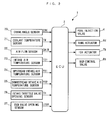
- FIG. 2 schematically shows the arrangement of a failure determination system 1.
- the failure determination system 1 includes an ECU 2 (see FIG. 2 ).
- the ECU 2 carries out various kinds of control of the internal combustion engine (hereinafter referred to as the "engine") 3, and at the same time carries out a failure determination process for determining failure of the air flow sensor 22.
- the engine 3 is a four-cylinder diesel engine installed on a vehicle, not shown, and includes four pairs of cylinders 3a and pistons 3b (only one pair of which is shown), a crankshaft 3c, and so forth.
- the engine 3 is provided with a crank angle sensor 20 and a coolant temperature sensor 21.
- the crank angle sensor 20 is formed by a magnet rotor and an MRE pickup, and delivers a CRK signal, which is a pulse signal, to the ECU 2 along with rotation of the crankshaft 3c.
- a CRK signal which is a pulse signal
- Each pulse of the CRK signal is generated whenever the crankshaft 3c rotates through a predetermined crank angle (e.g. 30°).
- the ECU 2 calculates rotational speed (hereinafter referred to as the "engine speed") NE of the engine 3 based on the CRK signal.
- the coolant temperature sensor 21 is implemented e.g. by a thermistor, and detects an engine coolant temperature TW, which is the temperature of engine coolant circulating through a cylinder block of the engine 3 to deliver a signal indicative of the sensed engine coolant temperature TW to the ECU 2.
- TW engine coolant temperature
- Fuel injection valves 4 (only one of which is shown) are mounted on the respective cylinders 3a of the engine 3. Each fuel injection valve 4 is electrically connected to the ECU 2. The valve-opening time period and the valve-opening timing of the fuel injection valve 4 are controlled by the ECU 2, whereby the fuel injection amount and fuel injection timing thereof are controlled.
- the air flow sensor 22, a turbocharger 6, an intake air temperature sensor 23, an upstream intake air pressure sensor 24, an intake throttle valve mechanism 7, and a downstream intake air pressure sensor 25, and so forth are provided at respective locations of an intake passage 5 of the engine 3 from upstream to downstream in the mentioned order.
- the air flow sensor 22 is formed by a hot-wire air flow meter, and detects the flow rate of air passing through an intake throttle valve 7a, referred to hereinafter, to deliver a signal indicative of the detected air flow rate to the ECU 2. It should be noted that a detected value GAIR of the air flow rate is calculated as a mass flow rate.
- the turbocharger 6 comprises a compressor blade 6a disposed in the intake passage 5 at a location downstream of the air flow sensor 22, a turbine blade 6b disposed in an intermediate portion of an exhaust passage 9, for rotating in unison with the compressor blade 6a, a plurality of variable vanes 6c (only two of which are shown), and a vane actuator 6d for actuating the variable vanes 6c.
- the compressor blade 6a integrally formed with the turbine blade 6b rotates, whereby air within the intake passage 5 is pressurized to cause the turbocharger 6 to perform a supercharging operation.
- variable vanes 6c are for varying boost pressure generated by the turbocharger 6, and are pivotally mounted on a wall of a housing (not shown) accommodating the turbine blade 6b.
- the variable vanes 6c are mechanically connected to the vane actuator 6d connected to the ECU 2.
- the ECU 2 changes the degree of opening of the variable vanes 6c via the vane actuator 6d to change the amount of exhaust gases blown to the turbine blade 6b, whereby the rotational speed of the turbine blade 6b, that is, the rotational speed of the compressor blade 6a, is changed to thereby control the boost pressure.
- the intake throttle valve mechanism 7 includes the intake throttle valve 7a, an ISV actuator 7b for actuating the intake throttle valve 7a, and so forth.
- the intake throttle valve 7a is pivotally disposed in the intake passage 5.
- the ISV actuator 7b is formed by combining a motor (not shown), and a reduction gear mechanism (not shown), and is electrically connected to the ECU 2.
- the ECU 2 controls the degree of opening of the intake throttle valve 7a via the ISV actuator 7b.
- the degree of opening of the intake passage 5 is changed by the intake throttle valve 7a, whereby the flow rate of air flowing though the intake passage 5 is adjusted.
- the intake air temperature sensor 23 and the upstream intake air pressure sensor 24 are provided in the intake passage 5 at respective locations immediately upstream of the intake throttle valve 7a, and the downstream intake air pressure sensor 25 is disposed in the intake passage 5 at a location immediately downstream of the intake throttle valve 7a.
- the intake air temperature sensor 23 detects the temperature of intake air flowing through the intake passage 5 (hereinafter referred to as the "intake air temperature”) T21 and delivers a detection signal indicative of the detected intake air temperature T21 to the ECU 2.
- the upstream intake air pressure sensor 24 is implemented by a semiconductor pressure sensor, and detects pressure within the intake passage 5 on the slightly upstream side of the intake throttle valve 7a (hereinafter referred to as the "upstream intake air pressure") P21 as absolute pressure, to deliver a detection signal indicative of the detected upstream intake air pressure P21 to the ECU 2.
- downstream intake air pressure sensor 25 is implemented by a semiconductor pressure sensor similar to that of the upstream intake air pressure sensor 24, and detects pressure within the intake passage 5 on the slightly downstream side of the intake throttle valve 7a (hereinafter referred to as the "downstream intake air pressure") P22 as absolute pressure, to deliver a detection signal indicative of the detected downstream intake air pressure P22 to the ECU 2.
- an intake throttle valve opening sensor 26 is disposed in the vicinity of the intake throttle valve 7a in the intake passage 5.
- This intake throttle valve opening sensor 26 detects the degree of opening of the intake throttle valve 7a (hereinafter referred to as the "intake throttle valve opening") TH, and delivers a detection signal indicative of the detected intake throttle valve opening TH to the ECU 2.
- the engine 3 is provided with an EGR device 8.
- This EGR device 8 recirculates part of exhaust gases discharged from the cylinders 3a into the exhaust passage 9 to the intake passage 5, and comprises an EGR passage 8a which connects between the intake passage 5 and the exhaust passage 9, and an EGR control valve 8b for opening and closing the EGR passage 8a.
- the EGR passage 8a has one end opening in a portion of the exhaust passage 9 upstream of the turbine blade 6b, and the other end opening in a portion of the intake passage 5 downstream of the downstream intake air pressure sensor 25.
- the EGR control valve 8b is implemented by a linear solenoid valve the valve lift of which is linearly varied between a maximum value and a minimum value thereof, and is electrically connected to the ECU 2.
- the ECU 2 changes the degree of opening of the EGR passage 8a via the EGR control valve 8b to thereby control the amount of exhaust gas recirculation, that is, the EGR amount.
- an EGR valve opening sensor 27 is disposed in the EGR passage 8a at a location in the vicinity of the EGR control valve 8b.
- the EGR valve opening sensor 27 detects the degree of opening of the EGR control valve 8b (hereinafter referred to as the "EGR valve opening") LEGR to deliver a signal indicative of the sensed EGR valve opening LEGR to the ECU 2.
- the ECU 2 is implemented by a microcomputer comprising a CPU, a RAM, a ROM, and an I/O interface (none of which are specifically shown).
- the ECU 2 determines operating conditions of the engine 3 based on the detection signals from the aforementioned sensors 20 to 27; carries out control processes including an EGR control process based on the determined operating conditions; and at the same time carries out a failure determination process for determining failure of the air flow sensor 22, as will be described hereinafter.
- the ECU 2 corresponds to estimated value-calculating means, failure determination means, opening degree parameter-detecting means, and failure determination-inhibiting means.
- FIG. 3 is a flowchart of the failure determination process for determining the failures of the air flow sensor 22.
- the present process is executed whenever a predetermined time period (e.g. 10 msec) elapses.
- a predetermined time period e.g. 10 msec
- This execution condition flag F_CHECK is set to 1 when conditions for executing failure determination of the air flow sensor 22 are satisfied.
- FIG. 4 is a flowchart of a subroutine of a process for determining whether or not the conditions for executing the failure determination are satisfied.
- a step 21 it is determined whether or not the engine 3 is being started. If the answer to this question is affirmative (YES), i.e. if the engine 3 is being started, it is judged that the air flow rate is liable to become unstable and hence the conditions for executing the failure determination are not satisfied, so that to indicate the fact, the execution condition flag F_CHECK is set to 0 (step 29), followed by terminating the present process.
- step 21 determines whether or not a pressure ratio between the downstream intake air pressure P22 and the upstream intake air pressure P21 (hereinafter simply referred to as the "pressure ratio") P22/P21 is not larger than a predetermined value PREF (e.g. 0.9) (step 22). If the answer to this question is negative (NO), i.e. if the pressure ratio P22/P21 is larger than the predetermined value PREF, it is judged that the differential pressure between the upstream intake air pressure P21 and the downstream intake air pressure P22 is small and hence the conditions for executing the failure determination are not satisfied, so that the above-described step 29 is executed.
- a pressure ratio between the downstream intake air pressure P22 and the upstream intake air pressure P21 hereinafter simply referred to as the "pressure ratio”
- step 23 it is determined whether or not an amount ⁇ TH of change in the intake throttle valve opening TH is not larger than a predetermined value THREF (e.g. 20%) (step 23).
- the change amount ⁇ TH represents the absolute value of the difference between an intake throttle valve opening TH obtained when the answer to the question of the step 22 has been changed from NO to YES and the present intake throttle valve opening TH. If the answer to this question is negative (NO), it is judged that the amount of change in the degree of opening of the intake throttle valve 7a is large, which makes the air flow rate liable to become unstable, and hence the conditions for executing the failure determination are not satisfied, so that the aforementioned step 29 is executed.
- a counted time TM of a timer (not shown) is not shorter than a predetermined time period TMREF (e.g. 0.3 sec) (step 24). This timer is started when the answer to the question of the step 22 has been changed from NO to YES, for counting a time period which has elapsed thereafter.
- step 29 If the answer to this question is negative (NO), i.e. if the predetermined time period has not elapsed after the pressure ratio P22/P21 becomes equal to or smaller than the predetermined value PREF, it is judged that there is a fear that the differential pressure between the upstream side and the downstream side of the intake throttle valve 7a is not sufficiently stable and hence the conditions for executing the failure determination are not satisfied, so that the above-mentioned step 29 is executed.
- the answer to the question of the step 24 is affirmative (YES)
- step 25 If the answer to this question is negative (NO), it is judged that the engine speed NE is not in an engine speed region suitable for the failure determination and hence the conditions for executing the failure determination are not satisfied, so that the above-mentioned step 29 is executed.
- step 26 it is determined whether or not an amount ⁇ EGR of change in the EGR valve opening LEGR is not larger than a predetermined value EGRREF (step 26).
- the change amount ⁇ EGR represents the absolute value of the difference between an EGR valve opening LEGR obtained when the answer to the question of the step 22 has been changed from NO to YES and the present EGR valve opening LEGR. If the answer to this question is negative (NO), it is judged that the amount of change in the EGR amount is large, which accordingly makes the air flow rate liable to become unstable, and hence the conditions for executing the failure determination are not satisfied, so that the aforementioned step 29 is executed.
- step 27 it is determined whether or not the engine coolant temperature TW is not lower than a predetermined temperature TWJUD (step 27). If the answer to this question is negative (NO), it is judged that the engine 3 is in a warming-up condition and hence the conditions for executing the failure determination are not satisfied, so that the aforementioned step 29 is executed.
- step 27 if the answer to the question of the step 27 is affirmative (YES), it is judged that the conditions for executing the failure determination are satisfied, so that to indicate the fact, the execution condition flag F_CHECK is set to 1 (step 28), followed by terminating the present process.
- step 2 if the answer to the question of the step 1 is negative (NO), i.e. if the conditions for executing the failure determination are not satisfied, the present process is immediately terminated. On the other hand, if the answer to the question of the step 1 is affirmative (YES), an estimated value GAIREST of the air flow rate, which is to be compared with the detected value GAIR of the air flow rate by the air flow sensor 22 (step 2), is calculated.
- FIG. 5 is a flowchart of a subroutine of a process for calculating the above estimated value GAIREST.
- a basic value GABASE of the estimated value of the air flow rate is calculated by searching a map shown in FIG. 6 according to the intake throttle valve opening TH and the pressure ratio P22/P21.
- the estimated value of the air flow rate can be calculated, as already proposed by the present applicant in Japanese Laid-Open Patent Publication (Kokai) No. 2007-205298 , using the upstream intake air pressure P21, the intake air temperature T21, and the pressure ratio P22/P21, by the following equation (1).
- Gair_est Aisv ⁇ P ⁇ 21 R ⁇ T ⁇ 21 ⁇ P ⁇ 22 P ⁇ 21 1 / ⁇ ⁇ 2 ⁇ ⁇ ⁇ - 1 1 - P ⁇ 22 P ⁇ 21 ⁇ - 1 / ⁇
- R represents the gas constant
- ⁇ represents a specific heat ratio between upstream air and downstream air in the vicinity of the intake throttle valve 7a.
- Aisv represents the effective opening area of the intake throttle valve 7a, and is calculated according to the intake throttle valve opening TH.
- the above-mentioned basic value GABASE corresponds to an air flow rate calculated by the equation (1) according to the pressure ratio P22/P21 assuming that the upstream intake air pressure P21 and the intake air temperature T21 are predetermined reference values CP and CT, respectively, and the intake throttle valve opening TH.
- the above-mentioned map is formed by determining the relationship between these e.g. by experiments in advance and storing the same.
- an intake air pressure-dependent correction coefficient KP is calculated by searching a table shown in FIG. 7 according to the upstream intake air pressure P21 (step 32).
- This intake air pressure-dependent correction coefficient KP corrects the basic value GABASE which is determined assuming that the upstream intake air pressure P21 is the reference value CP in the above-described equation (1), according to an actual upstream intake air pressure P21. Therefore, in the above table, the intake air pressure-dependent correction coefficient KP is set to 1 when the upstream intake air pressure P21 is equal to the reference value CP, and is set to a larger value as the upstream intake air pressure P21 is larger.
- the intake air pressure-dependent correction coefficient KP is determined in advance e.g. by experiments.
- an intake air temperature correction coefficient KT is calculated by searching a table shown in FIG. 8 according to the intake air temperature T21 (step 33).
- This intake air temperature correction coefficient KT corrects the basic value GABASE which is determined assuming that the intake air temperature T21 is the reference value CT in the above-described equation (1), according to an actual intake air temperature T21. Therefore, in the above table, the intake air temperature correction coefficient KT is set to 1 when the intake air temperature T21 is equal to the reference value CT, and when the intake air temperature T21 is lower than the reference value CT, the intake air temperature correction coefficient KT linearly increases toward 1, whereas when the intake air temperature T21 is higher than the reference value CT, the intake air temperature correction coefficient KT linearly decreases from 1.
- the intake air temperature correction coefficient KT is determined in advance e.g. by experiments.
- the estimated value GAIREST of the air flow rate is calculated (step 34), followed by terminating the present process.
- a lower limit value GALMTL of the estimated value GAIREST of the air flow rate is calculated using the estimated value GAIREST by the following equation (3) (step 4) :
- GALMTL GAIREST ⁇ A ⁇ 2 + B ⁇ 2 wherein A2 and B2 represent constants, and are set to values smaller than the above-mentioned constants A1 and B1, respectively.
- step 5 it is determined whether or not the detected value GAIR of the air flow rate is not smaller than the lower limit value GALMTL (step 5). If the answer to this question is negative (NO), it is judged that the detected value GAIR of the air flow rate has largely deviated from the estimated value GAIREST across the lower limit value GALMTL, and the process proceeds to a step 6, wherein a counter value CNTL of a counter (not shown) is incremented, and then the process proceeds to a step 7.
- step 7 it is determined whether or not the counter value CNTL is larger than a predetermined value CNTREF. If the answer to this question is affirmative (YES), i.e. if the state in which the detected value GAIR of the air flow rate has largely deviated from the estimated value GAIREST across the lower limit value GALMTL has occurred a predetermined number of times, it is determined that the air flow sensor 22 is faulty in a state where the detected value GAIR exceeds the lower limit value GALMTL, and to indicate the fact, a LOW-side failure determination flag F_AFMNGL is set to 1 (step 8), followed by terminating the present process.
- a failure determination flag F_AFMNG is set to 0 (step 9), followed by terminating the present process.
- step 10 determines whether or not the detected value GAIR of the air flow rate is not larger than the upper limit value GALMTH (step 10). If the answer to this question is affirmative (YES), i.e. if the detected value GAIR of the air flow rate is between the lower limit value GALMTL and the upper limit value GALMTH, it is judged that the air flow sensor 22 is normal, and the above-mentioned step 9 is executed.
- step 10 determines that the detected value GAIR of the air flow rate has largely deviated from the estimated value GAIREST across the upper limit value GALMTH, and the process proceeds to a step 11, wherein a counter value CNTH of the counter (not shown) is incremented, and then the process proceeds to a step 12.
- step 12 it is determined whether or not the counter value CNTH is larger than the predetermined value CNTREF. If the answer to this question is affirmative (YES), i.e. if the state in which the detected value GAIR of the air flow rate has largely deviated from the estimated value GAIREST across the upper limit value GALMTH has occurred a predetermined number of times, it is determined that the air flow sensor 22 is faulty in a state where the detected value GAIR exceeds the upper limit value GALMTH, and to indicate the fact, a HIGH-side failure determination flag F_AFMNGH is set to 1 (step 13), followed by terminating the present process.
- YES i.e. if the state in which the detected value GAIR of the air flow rate has largely deviated from the estimated value GAIREST across the upper limit value GALMTH has occurred a predetermined number of times, it is determined that the air flow sensor 22 is faulty in a state where the detected value GAIR exceeds the upper limit value GALMTH, and to indicate the fact,
- the failure determination flag F_AFMNG is set to 0 (step 9), followed by terminating the present process.
- the estimated value GABASE of the air flow rate is calculated according to the pressure ratio P22/P21 between the downstream intake air pressure P22 and the upstream intake air pressure P21, the intake throttle valve opening TH, the upstream intake air pressure P21, and the intake air temperature T21, and the detected value GAIR of the air flow rate is compared with the estimated value GABASE to thereby carry out the abnormality determination of the air flow sensor 22.
- the estimated value GAIREST of the air flow rate is calculated using the pressure ratio P22/P21 between the downstream intake air pressure P22 and the upstream intake air pressure P21, it is possible to properly calculate the estimated value GAIREST, thereby making it possible to properly determine the failure of the air flow sensor 22.
- the failure determination of the air flow sensor 22 is inhibited when the pressure ratio P22/P21 is larger than the predetermined value PREF (NO to the step 22 in FIG. 4 ), and hence the failure determination is performed only in a situation where the accuracy of calculating the estimated value GAIREST of the air flow rate is high, whereby it is possible to improve the accuracy of determining the failure of the air flow sensor 22.
- the estimated value GAIREST of the air flow rate is calculated by multiplying the basic value GABASE calculated from the map according to the pressure ratio P22/P21 and the intake throttle valve opening TH, by the correction coefficients KP and KT calculated from the respective maps according to the upstream intake air pressure P21 and the intake air temperature T21. This makes it possible to reduce computation load, compared with a case where the estimated value GAIREST of the air flow rate is directly calculated using the aforementioned equation (1) according to the pressure ratio P22/P21 and so forth.
- the failure of the air flow sensor 22 is determined separately based on each of the upper limit value GALMTH and the lower limit value GALMTL, and hence it is possible to identify a mode of failure, that is, across which of the upper limit value GALMTH and the lower limit value GALMTL the failure has occurred.
- the present invention is by no means limited to the embodiment described above, but it can be practiced in various forms.
- the pressure ratio P22/P21 between the downstream intake air pressure P22 and the upstream intake air pressure P21 by way of example, this is not limitative, but any other suitable parameter can be used.
- the intake throttle valve opening TH may be used instead of the pressure ratio P22/P21 or in combination with this. In this case, the failure determination of the air flow sensor 22 is inhibited when the intake throttle valve opening TH is larger than a predetermined opening.
- an intake air temperature used for calculation of the estimated value GAIREST of the air flow rate there is used the temperature of intake air upstream of the intake throttle valve 7a, the temperature of intake air downstream of the intake throttle valve 7a may be used.
- the air flow sensor 22 is formed by the hot-wire air flow meter
- the air flow rate-detecting device to which is applied the present invention is not limited to this, but any suitable device may be used insofar as it can detect the flow rate of air flowing through the intake passage.
- a Karman vortex air flow meter or a movable plate-type air flow meter may be used as the air flow rate-detecting device.
- the intake throttle valve mechanism 7 of pivot type is used as an air flow rate adjustment mechanism
- the air flow rate adjustment mechanism is not limited to this, but any suitable device including a shutter may be used as the air flow rate adjustment mechanism insofar as it is capable of adjusting the air flow rate.
- the present invention is applied to the diesel engine installed on an automotive vehicle by way of example, this is not limitative, but it can be applied to various types of engines, such as gasoline engines other than diesel engine, and engines for other than automotive vehicles, such as engines for ship propulsion machines, e.g. an outboard motor having a vertically-disposed crankshaft. Further, it is possible to change details of the construction of the embodiment within the spirit and scope of the present invention.
- the failure determination system and method for the air flow rate-detecting device can be applied to various internal combustion engines as a failure determination system and method which maintain the accuracy of calculating an estimated value of an air flow rate, which is to be compared with a value of the same detected by the air flow rate-detecting device, to thereby improve the accuracy of failure determination.
Landscapes
- Engineering & Computer Science (AREA)
- Chemical & Material Sciences (AREA)
- Combustion & Propulsion (AREA)
- Mechanical Engineering (AREA)
- General Engineering & Computer Science (AREA)
- Combined Controls Of Internal Combustion Engines (AREA)
Abstract
Description
- The present invention relates to a failure determination system and method for an air flow rate-detecting device that detects a flow rate of air flowing through an intake passage of an internal combustion engine.
- Conventionally, as a failure determination system of this kind, there has been known, for example, one disclosed in
Patent Literature 1. In this failure determination system, based on an air flow rate detected by an air flow rate-detecting device and the rotational speed of the engine, a first calculated value of the air flow rate is calculated, and a second calculated value of the air flow rate is calculated based on detected atmospheric pressure, intake air pressure, intake air temperature, and engine speed. Further, a third calculated value of the air flow rate is calculated based on a throttle valve opening, the atmospheric pressure, the intake air temperature, and the engine speed. Then, these first to third calculated values are compared, and when the state in which the first calculated value is largely different from the second and third calculated values frequently occurs, it is determined that the air flow rate-detecting device is faulty. - As described above, in the conventional failure determination system, to calculate the second and third calculated values, the atmospheric pressure is used which does not directly represent the physical properties of air in an intake passage, which makes a calculation error liable to occur with respect to an actual air flow rate. In this case, the accuracy of determining failure of the air flow rate-detecting device, which is performed based on comparison with the second and third calculated values, is degraded.
- The present invention has been made to provide a solution to the above-described problem, and an object thereof is to provide a failure determination system and method for an air flow rate-detecting device, which are capable of maintaining the accuracy of calculating an estimated value of an air flow rate, which is to be compared with a detected value by the air flow rate-detecting device, to thereby improve the accuracy of failure determination.
-
- [Patent Literature 1] Japanese Laid-Open Patent Publication (Kokai) No.
H11-324783 - To attain the above object, in a first aspect of the present invention, there is provided a failure determination system for an air flow rate-detecting device that detects a flow rate of air flowing through an intake passage of an internal combustion engine, comprising an air flow rate adjustment mechanism disposed in an intermediate portion of the intake passage, for changing a degree of opening of the intake passage to thereby adjust the air flow rate, estimated value-calculating means for calculating an estimated value of the air flow rate according to a relationship between respective pressures in the intake passage on an upstream side and a downstream side of the air flow rate adjustment mechanism, failure determination means for determining failure of the air flow rate-detecting device based on a result of comparison between the calculated estimated value of the air flow rate and a detected value of the air flow rate by the air flow rate-detecting device, opening degree parameter-detecting means for detecting an opening degree parameter indicative of a degree of opening of the intake passage, and failure determination-inhibiting means for inhibiting failure determination of the air flow rate-detecting device by the failure determination means when the degree of opening of the intake passage represented by the detected opening degree parameter is larger than a predetermined value.
- According to this failure determination system for an air flow rate-detecting device, the air flow rate adjustment mechanism is disposed in the intermediate portion of the intake passage, and the air flow rate adjustment mechanism changes the degree of opening of the intake passage, whereby the flow rate of air flowing through the intake passage is adjusted. When the degree of opening of the intake passage is changed to narrow the intake passage, a differential pressure is generated between the upstream side and the downstream side of the air flow rate adjustment mechanism. According to the failure determination system of the present invention, the estimated value of the air flow rate is calculated using the thus generated differential pressure according to the relationship between the pressures in the intake passage on the upstream side and the downstream side of the air flow rate adjustment mechanism, so that it is possible to properly calculate the estimated value. This makes it possible to properly determine failure of the air flow rate-detecting device based on a result of comparison between the calculated estimated value and the detected value of the air flow rate by the air flow rate-detecting device.
- Further, as described above, the estimated value of the air flow rate is calculated using the differential pressure, and hence when the degree of opening of the intake passage is large, the differential pressure becomes smaller, which makes the accuracy of calculating the estimated value liable to be lowered. According to the present invention, the opening degree parameter of the air flow rate adjustment mechanism is detected, and when the degree of opening of the intake passage represented by the detected opening degree parameter is larger than the predetermined value, the failure determination of the air flow rate-detecting device is inhibited. Therefore, the failure determination is performed only in a situation where the accuracy of calculating the estimated value of the air flow rate is estimated to be high, and hence it is possible to improve the accuracy of failure determination.
- Preferably, the air flow rate adjustment mechanism includes an adjustment valve for adjusting the air flow rate by changing the degree of opening of the intake passage, and the opening degree parameter is a degree of opening of the adjustment valve, the failure determination-inhibiting means inhibiting failure determination by the failure determination means when the degree of opening of the adjustment valve is larger than a predetermined opening degree.
- With the configuration of this preferred embodiment, the degree of opening of the intake passage is changed by the adjustment valve, and hence the degree of opening of the adjustment valve directly excellently represents the degree of opening of the intake passage. Therefore, by inhibiting the failure determination of the air flow rate-detecting device when the detected degree of opening of the adjustment valve is larger than the predetermined opening degree, it is possible to improve the accuracy of failure determination of the air flow rate-detecting device.
- Preferably, the failure determination system further comprises upstream intake air pressure-detecting means for detecting pressure in the intake passage in the vicinity of and at the same time at a location upstream of the air flow rate adjustment mechanism, as upstream intake air pressure, and downstream intake air pressure-detecting means for detecting pressure in the intake passage in the vicinity of and at the same time at a location downstream of the air flow rate adjustment mechanism, as downstream intake air pressure, and the opening degree parameter is a pressure ratio between the detected downstream intake air pressure and the detected upstream intake air pressure, the failure determination-inhibiting means inhibiting failure determination by the failure determination means when the pressure ratio is larger than a predetermined value.
- With the configuration of this preferred embodiment, the pressure ratio between the detected pressures in the intake passage in the vicinity of and at the respective locations upstream and downstream of the air flow rate adjustment mechanism is used as the opening degree parameter. As the pressure ratio is larger, it represents that the differential pressure between the pressures in the intake passage on the upstream side and the downstream side of the air flow rate adjustment mechanism is smaller. Therefore, by inhibiting the failure determination of the air flow rate-detecting device when the pressure ratio is larger than the predetermined value, it is possible to improve the accuracy of failure determination of the air flow rate-detecting device.
- To attain the above object, in a second aspect of the present invention, there is provided a failure determination method for an air flow rate-detecting device that detects a flow rate of air flowing through an intake passage of an internal combustion engine, the flow rate of air being adjusted by changing a degree of opening of the intake passage using an air flow rate adjustment mechanism, comprising an estimated value-calculating step of calculating an estimated value of the air flow rate according to a relationship between respective pressures in the intake passage on an upstream side and a downstream side of the air flow rate adjustment mechanism, a failure determination step of determining failure of the air flow rate-detecting device based on a result of comparison between the calculated estimated value of the air flow rate and a detected value of the air flow rate by the air flow rate-detecting device, an opening degree parameter-detecting step of detecting an opening degree parameter indicative of a degree of opening of the intake passage, and a failure determination-inhibiting step of inhibiting failure determination of the air flow rate-detecting device in the failure determination step when the degree of opening of the intake passage represented by the detected opening degree parameter is larger than a predetermined value.
- With the configuration according to the second aspect of the present invention, it is possible to obtain the same advantageous effects as provided by the first aspect of the present invention.
- Preferably, the air flow rate adjustment mechanism includes an adjustment valve for adjusting the air flow rate by changing the degree of opening of the intake passage, and the opening degree parameter is a degree of opening of the adjustment valve, the failure determination-inhibiting step including inhibiting failure determination in the failure determination step when the degree of opening of the adjustment valve is larger than a predetermined opening degree.
- Preferably, the failure determination method further comprises an upstream intake air pressure-detecting step of detecting pressure in the intake passage in the vicinity of and at the same time at a location upstream of the air flow rate adjustment mechanism, as upstream intake air pressure, and a downstream intake air pressure-detecting step of detecting pressure in the intake passage in the vicinity of and at the same time at a location downstream of the air flow rate adjustment mechanism, as downstream intake air pressure, and the opening degree parameter is a pressure ratio between the detected downstream intake air pressure and the detected upstream intake air pressure, the failure determination-inhibiting step including inhibiting failure determination in the failure determination step when the pressure ratio is larger than a predetermined value.
- According to these preferred embodiments, it is possible to obtain the same advantageous effects as provided by the respective corresponding preferred embodiments of the first aspect of the present invention.
-
- [
FIG. 1 ] A schematic view of a failure determination system according to an embodiment of the present invention and an internal combustion engine incorporating the same. - [
FIG. 2 ] A schematic block diagram of the failure determination system. - [
FIG. 3 ] A flowchart of a failure determination process for determining failure of an air flow sensor. - [
FIG. 4 ] A flowchart of a subroutine of a process for determining whether or not execution conditions for executing failure determination of the air flow sensor are satisfied. - [
FIG. 5 ] A flowchart of a subroutine of a process for calculating the estimated value of an air flow rate. - [
FIG. 6 ] A view showing an example of a map for use in calculating a basic value. - [
FIG. 7 ] A view showing an example of a table for use in calculating an intake air pressure-dependent correction term. - [
FIG. 8 ] A view showing an example of a table for use in calculating an intake air temperature-dependent correction term. - Hereafter, the invention will now be described in detail with reference to drawings showing a preferred embodiment thereof.
FIG. 1 schematically shows the arrangement of aninternal combustion engine 3 incorporating anair flow sensor 22 as an air flow rate-detecting device, to which is applied the present invention.FIG. 2 schematically shows the arrangement of afailure determination system 1. Thefailure determination system 1 includes an ECU 2 (seeFIG. 2 ). As will be described hereinafter, theECU 2 carries out various kinds of control of the internal combustion engine (hereinafter referred to as the "engine") 3, and at the same time carries out a failure determination process for determining failure of theair flow sensor 22. - The
engine 3 is a four-cylinder diesel engine installed on a vehicle, not shown, and includes four pairs of cylinders 3a andpistons 3b (only one pair of which is shown), a crankshaft 3c, and so forth. Theengine 3 is provided with acrank angle sensor 20 and acoolant temperature sensor 21. - The
crank angle sensor 20 is formed by a magnet rotor and an MRE pickup, and delivers a CRK signal, which is a pulse signal, to theECU 2 along with rotation of the crankshaft 3c. Each pulse of the CRK signal is generated whenever the crankshaft 3c rotates through a predetermined crank angle (e.g. 30°). The ECU 2 calculates rotational speed (hereinafter referred to as the "engine speed") NE of theengine 3 based on the CRK signal. - Further, the
coolant temperature sensor 21 is implemented e.g. by a thermistor, and detects an engine coolant temperature TW, which is the temperature of engine coolant circulating through a cylinder block of theengine 3 to deliver a signal indicative of the sensed engine coolant temperature TW to theECU 2. - Fuel injection valves 4 (only one of which is shown) are mounted on the respective cylinders 3a of the
engine 3. Eachfuel injection valve 4 is electrically connected to theECU 2. The valve-opening time period and the valve-opening timing of thefuel injection valve 4 are controlled by theECU 2, whereby the fuel injection amount and fuel injection timing thereof are controlled. - On the other hand, the
air flow sensor 22, aturbocharger 6, an intakeair temperature sensor 23, an upstream intakeair pressure sensor 24, an intakethrottle valve mechanism 7, and a downstream intakeair pressure sensor 25, and so forth are provided at respective locations of anintake passage 5 of theengine 3 from upstream to downstream in the mentioned order. - The
air flow sensor 22 is formed by a hot-wire air flow meter, and detects the flow rate of air passing through an intake throttle valve 7a, referred to hereinafter, to deliver a signal indicative of the detected air flow rate to theECU 2. It should be noted that a detected value GAIR of the air flow rate is calculated as a mass flow rate. - Further, the
turbocharger 6 comprises acompressor blade 6a disposed in theintake passage 5 at a location downstream of theair flow sensor 22, a turbine blade 6b disposed in an intermediate portion of anexhaust passage 9, for rotating in unison with thecompressor blade 6a, a plurality ofvariable vanes 6c (only two of which are shown), and avane actuator 6d for actuating thevariable vanes 6c. - In the
turbocharger 6, as the turbine blade 6b is driven for rotation by exhaust gases flowing through theexhaust passage 9, thecompressor blade 6a integrally formed with the turbine blade 6b rotates, whereby air within theintake passage 5 is pressurized to cause theturbocharger 6 to perform a supercharging operation. - Further, the
variable vanes 6c are for varying boost pressure generated by theturbocharger 6, and are pivotally mounted on a wall of a housing (not shown) accommodating the turbine blade 6b. Thevariable vanes 6c are mechanically connected to thevane actuator 6d connected to theECU 2. TheECU 2 changes the degree of opening of thevariable vanes 6c via thevane actuator 6d to change the amount of exhaust gases blown to the turbine blade 6b, whereby the rotational speed of the turbine blade 6b, that is, the rotational speed of thecompressor blade 6a, is changed to thereby control the boost pressure. - On the other hand, the intake
throttle valve mechanism 7 includes the intake throttle valve 7a, anISV actuator 7b for actuating the intake throttle valve 7a, and so forth. The intake throttle valve 7a is pivotally disposed in theintake passage 5. TheISV actuator 7b is formed by combining a motor (not shown), and a reduction gear mechanism (not shown), and is electrically connected to theECU 2. TheECU 2 controls the degree of opening of the intake throttle valve 7a via theISV actuator 7b. Thus, the degree of opening of theintake passage 5 is changed by the intake throttle valve 7a, whereby the flow rate of air flowing though theintake passage 5 is adjusted. - Further, the intake
air temperature sensor 23 and the upstream intakeair pressure sensor 24 are provided in theintake passage 5 at respective locations immediately upstream of the intake throttle valve 7a, and the downstream intakeair pressure sensor 25 is disposed in theintake passage 5 at a location immediately downstream of the intake throttle valve 7a. - The intake
air temperature sensor 23 detects the temperature of intake air flowing through the intake passage 5 (hereinafter referred to as the "intake air temperature") T21 and delivers a detection signal indicative of the detected intake air temperature T21 to theECU 2. Further, the upstream intakeair pressure sensor 24 is implemented by a semiconductor pressure sensor, and detects pressure within theintake passage 5 on the slightly upstream side of the intake throttle valve 7a (hereinafter referred to as the "upstream intake air pressure") P21 as absolute pressure, to deliver a detection signal indicative of the detected upstream intake air pressure P21 to theECU 2. - Furthermore, the downstream intake
air pressure sensor 25 is implemented by a semiconductor pressure sensor similar to that of the upstream intakeair pressure sensor 24, and detects pressure within theintake passage 5 on the slightly downstream side of the intake throttle valve 7a (hereinafter referred to as the "downstream intake air pressure") P22 as absolute pressure, to deliver a detection signal indicative of the detected downstream intake air pressure P22 to theECU 2. - On the other hand, an intake throttle
valve opening sensor 26 is disposed in the vicinity of the intake throttle valve 7a in theintake passage 5. This intake throttlevalve opening sensor 26 detects the degree of opening of the intake throttle valve 7a (hereinafter referred to as the "intake throttle valve opening") TH, and delivers a detection signal indicative of the detected intake throttle valve opening TH to theECU 2. - Further, the
engine 3 is provided with anEGR device 8. ThisEGR device 8 recirculates part of exhaust gases discharged from the cylinders 3a into theexhaust passage 9 to theintake passage 5, and comprises anEGR passage 8a which connects between theintake passage 5 and theexhaust passage 9, and anEGR control valve 8b for opening and closing theEGR passage 8a. TheEGR passage 8a has one end opening in a portion of theexhaust passage 9 upstream of the turbine blade 6b, and the other end opening in a portion of theintake passage 5 downstream of the downstream intakeair pressure sensor 25. - The
EGR control valve 8b is implemented by a linear solenoid valve the valve lift of which is linearly varied between a maximum value and a minimum value thereof, and is electrically connected to theECU 2. TheECU 2 changes the degree of opening of theEGR passage 8a via theEGR control valve 8b to thereby control the amount of exhaust gas recirculation, that is, the EGR amount. Further, an EGRvalve opening sensor 27 is disposed in theEGR passage 8a at a location in the vicinity of theEGR control valve 8b. The EGRvalve opening sensor 27 detects the degree of opening of theEGR control valve 8b (hereinafter referred to as the "EGR valve opening") LEGR to deliver a signal indicative of the sensed EGR valve opening LEGR to theECU 2. - On the other hand, the
ECU 2 is implemented by a microcomputer comprising a CPU, a RAM, a ROM, and an I/O interface (none of which are specifically shown). TheECU 2 determines operating conditions of theengine 3 based on the detection signals from theaforementioned sensors 20 to 27; carries out control processes including an EGR control process based on the determined operating conditions; and at the same time carries out a failure determination process for determining failure of theair flow sensor 22, as will be described hereinafter. It should be noted that in the present embodiment, theECU 2 corresponds to estimated value-calculating means, failure determination means, opening degree parameter-detecting means, and failure determination-inhibiting means. -
FIG. 3 is a flowchart of the failure determination process for determining the failures of theair flow sensor 22. The present process is executed whenever a predetermined time period (e.g. 10 msec) elapses. In the present process, first, in a step 1 (shown as S1 in abbreviated form inFIG. 3 ; the following steps are also shown in abbreviated form), it is determined whether or not an execution condition flag F_CHECK is equal to 1. This execution condition flag F_CHECK is set to 1 when conditions for executing failure determination of theair flow sensor 22 are satisfied. -
FIG. 4 is a flowchart of a subroutine of a process for determining whether or not the conditions for executing the failure determination are satisfied. In the present process, first, in astep 21, it is determined whether or not theengine 3 is being started. If the answer to this question is affirmative (YES), i.e. if theengine 3 is being started, it is judged that the air flow rate is liable to become unstable and hence the conditions for executing the failure determination are not satisfied, so that to indicate the fact, the execution condition flag F_CHECK is set to 0 (step 29), followed by terminating the present process. - On the other hand, if the answer to the question of the
step 21 is negative (NO), it is determined whether or not a pressure ratio between the downstream intake air pressure P22 and the upstream intake air pressure P21 (hereinafter simply referred to as the "pressure ratio") P22/P21 is not larger than a predetermined value PREF (e.g. 0.9) (step 22). If the answer to this question is negative (NO), i.e. if the pressure ratio P22/P21 is larger than the predetermined value PREF, it is judged that the differential pressure between the upstream intake air pressure P21 and the downstream intake air pressure P22 is small and hence the conditions for executing the failure determination are not satisfied, so that the above-describedstep 29 is executed. - Further, if the answer to the question of the
step 22 is affirmative (YES), it is determined whether or not an amount ΔTH of change in the intake throttle valve opening TH is not larger than a predetermined value THREF (e.g. 20%) (step 23). The change amount Δ TH represents the absolute value of the difference between an intake throttle valve opening TH obtained when the answer to the question of thestep 22 has been changed from NO to YES and the present intake throttle valve opening TH. If the answer to this question is negative (NO), it is judged that the amount of change in the degree of opening of the intake throttle valve 7a is large, which makes the air flow rate liable to become unstable, and hence the conditions for executing the failure determination are not satisfied, so that theaforementioned step 29 is executed. - On the other hand, if the answer to the question of the
step 23 is affirmative (YES), it is determined whether or not a counted time TM of a timer (not shown) is not shorter than a predetermined time period TMREF (e.g. 0.3 sec) (step 24). This timer is started when the answer to the question of thestep 22 has been changed from NO to YES, for counting a time period which has elapsed thereafter. - If the answer to this question is negative (NO), i.e. if the predetermined time period has not elapsed after the pressure ratio P22/P21 becomes equal to or smaller than the predetermined value PREF, it is judged that there is a fear that the differential pressure between the upstream side and the downstream side of the intake throttle valve 7a is not sufficiently stable and hence the conditions for executing the failure determination are not satisfied, so that the above-mentioned
step 29 is executed. On the other hand, if the answer to the question of thestep 24 is affirmative (YES), it is determined whether or not the engine speed NE is not lower than a lower limit value NEL (e.g. 550 rpm), and at the same time is not higher than an upper limit value NEH (e.g. 4000 rpm) (step 25). If the answer to this question is negative (NO), it is judged that the engine speed NE is not in an engine speed region suitable for the failure determination and hence the conditions for executing the failure determination are not satisfied, so that the above-mentionedstep 29 is executed. - On the other hand, if the answer to the question of the
step 25 is affirmative (YES), it is determined whether or not an amount ΔEGR of change in the EGR valve opening LEGR is not larger than a predetermined value EGRREF (step 26). The change amount ΔEGR represents the absolute value of the difference between an EGR valve opening LEGR obtained when the answer to the question of thestep 22 has been changed from NO to YES and the present EGR valve opening LEGR. If the answer to this question is negative (NO), it is judged that the amount of change in the EGR amount is large, which accordingly makes the air flow rate liable to become unstable, and hence the conditions for executing the failure determination are not satisfied, so that theaforementioned step 29 is executed. - Further, if the answer to the question of the
step 26 is affirmative (YES), it is determined whether or not the engine coolant temperature TW is not lower than a predetermined temperature TWJUD (step 27). If the answer to this question is negative (NO), it is judged that theengine 3 is in a warming-up condition and hence the conditions for executing the failure determination are not satisfied, so that theaforementioned step 29 is executed. - On the other hand, if the answer to the question of the
step 27 is affirmative (YES), it is judged that the conditions for executing the failure determination are satisfied, so that to indicate the fact, the execution condition flag F_CHECK is set to 1 (step 28), followed by terminating the present process. - Referring again to
FIG. 3 , if the answer to the question of thestep 1 is negative (NO), i.e. if the conditions for executing the failure determination are not satisfied, the present process is immediately terminated. On the other hand, if the answer to the question of thestep 1 is affirmative (YES), an estimated value GAIREST of the air flow rate, which is to be compared with the detected value GAIR of the air flow rate by the air flow sensor 22 (step 2), is calculated. -
FIG. 5 is a flowchart of a subroutine of a process for calculating the above estimated value GAIREST. In the present process, first, in astep 31, a basic value GABASE of the estimated value of the air flow rate is calculated by searching a map shown inFIG. 6 according to the intake throttle valve opening TH and the pressure ratio P22/P21. - The estimated value of the air flow rate can be calculated, as already proposed by the present applicant in Japanese Laid-Open Patent Publication (Kokai) No.
2007-205298 
wherein R represents the gas constant, and κ represents a specific heat ratio between upstream air and downstream air in the vicinity of the intake throttle valve 7a. Further, Aisv represents the effective opening area of the intake throttle valve 7a, and is calculated according to the intake throttle valve opening TH. The above-mentioned basic value GABASE corresponds to an air flow rate calculated by the equation (1) according to the pressure ratio P22/P21 assuming that the upstream intake air pressure P21 and the intake air temperature T21 are predetermined reference values CP and CT, respectively, and the intake throttle valve opening TH. The above-mentioned map is formed by determining the relationship between these e.g. by experiments in advance and storing the same. - Next, an intake air pressure-dependent correction coefficient KP is calculated by searching a table shown in
FIG. 7 according to the upstream intake air pressure P21 (step 32). This intake air pressure-dependent correction coefficient KP corrects the basic value GABASE which is determined assuming that the upstream intake air pressure P21 is the reference value CP in the above-described equation (1), according to an actual upstream intake air pressure P21. Therefore, in the above table, the intake air pressure-dependent correction coefficient KP is set to 1 when the upstream intake air pressure P21 is equal to the reference value CP, and is set to a larger value as the upstream intake air pressure P21 is larger. The intake air pressure-dependent correction coefficient KP is determined in advance e.g. by experiments. - Next, an intake air temperature correction coefficient KT is calculated by searching a table shown in
FIG. 8 according to the intake air temperature T21 (step 33). This intake air temperature correction coefficient KT corrects the basic value GABASE which is determined assuming that the intake air temperature T21 is the reference value CT in the above-described equation (1), according to an actual intake air temperature T21. Therefore, in the above table, the intake air temperature correction coefficient KT is set to 1 when the intake air temperature T21 is equal to the reference value CT, and when the intake air temperature T21 is lower than the reference value CT, the intake air temperature correction coefficient KT linearly increases toward 1, whereas when the intake air temperature T21 is higher than the reference value CT, the intake air temperature correction coefficient KT linearly decreases from 1. The intake air temperature correction coefficient KT is determined in advance e.g. by experiments. - Then, by multiplying the basic value GABASE by the intake air pressure-dependent correction coefficient KP and the intake air temperature correction coefficient KT, the estimated value GAIREST of the air flow rate is calculated (step 34), followed by terminating the present process.
- Referring again to
FIG. 3 , in astep 3 following thestep 2, an upper limit value GALMTH of the estimated value GAIREST of the air flow rate is calculated using the estimated value GAIREST calculated as described above by the following equation (2):
wherein A1 and B1 represent constants. - Next, a lower limit value GALMTL of the estimated value GAIREST of the air flow rate is calculated using the estimated value GAIREST by the following equation (3) (step 4) :

wherein A2 and B2 represent constants, and are set to values smaller than the above-mentioned constants A1 and B1, respectively. - Then, it is determined whether or not the detected value GAIR of the air flow rate is not smaller than the lower limit value GALMTL (step 5). If the answer to this question is negative (NO), it is judged that the detected value GAIR of the air flow rate has largely deviated from the estimated value GAIREST across the lower limit value GALMTL, and the process proceeds to a
step 6, wherein a counter value CNTL of a counter (not shown) is incremented, and then the process proceeds to astep 7. - In the
step 7, it is determined whether or not the counter value CNTL is larger than a predetermined value CNTREF. If the answer to this question is affirmative (YES), i.e. if the state in which the detected value GAIR of the air flow rate has largely deviated from the estimated value GAIREST across the lower limit value GALMTL has occurred a predetermined number of times, it is determined that theair flow sensor 22 is faulty in a state where the detected value GAIR exceeds the lower limit value GALMTL, and to indicate the fact, a LOW-side failure determination flag F_AFMNGL is set to 1 (step 8), followed by terminating the present process. - On the other hand, if the answer to the question of the
step 7 is negative (NO), it is determined that theair flow sensor 22 is normal, and to indicate the fact, a failure determination flag F_AFMNG is set to 0 (step 9), followed by terminating the present process. - Further, if the answer to the question of the
step 5 is affirmative (YES), i.e. if the detected value GAIR of the air flow rate is not smaller than the lower limit value GALMTL, it is determined whether or not the detected value GAIR of the air flow rate is not larger than the upper limit value GALMTH (step 10). If the answer to this question is affirmative (YES), i.e. if the detected value GAIR of the air flow rate is between the lower limit value GALMTL and the upper limit value GALMTH, it is judged that theair flow sensor 22 is normal, and the above-mentionedstep 9 is executed. - On the other hand, if the answer to the question of the
step 10 is negative (NO), it is determined that the detected value GAIR of the air flow rate has largely deviated from the estimated value GAIREST across the upper limit value GALMTH, and the process proceeds to astep 11, wherein a counter value CNTH of the counter (not shown) is incremented, and then the process proceeds to astep 12. - In the
step 12, it is determined whether or not the counter value CNTH is larger than the predetermined value CNTREF. If the answer to this question is affirmative (YES), i.e. if the state in which the detected value GAIR of the air flow rate has largely deviated from the estimated value GAIREST across the upper limit value GALMTH has occurred a predetermined number of times, it is determined that theair flow sensor 22 is faulty in a state where the detected value GAIR exceeds the upper limit value GALMTH, and to indicate the fact, a HIGH-side failure determination flag F_AFMNGH is set to 1 (step 13), followed by terminating the present process. - On the other hand, if the answer to the question of the
step 12 is negative (NO), it is determined that theair flow sensor 22 is normal, and to indicate the fact, the failure determination flag F_AFMNG is set to 0 (step 9), followed by terminating the present process. - As described heretofore, according to the present embodiment, the estimated value GABASE of the air flow rate is calculated according to the pressure ratio P22/P21 between the downstream intake air pressure P22 and the upstream intake air pressure P21, the intake throttle valve opening TH, the upstream intake air pressure P21, and the intake air temperature T21, and the detected value GAIR of the air flow rate is compared with the estimated value GABASE to thereby carry out the abnormality determination of the
air flow sensor 22. - As described above, since the estimated value GAIREST of the air flow rate is calculated using the pressure ratio P22/P21 between the downstream intake air pressure P22 and the upstream intake air pressure P21, it is possible to properly calculate the estimated value GAIREST, thereby making it possible to properly determine the failure of the
air flow sensor 22. - Further, the failure determination of the
air flow sensor 22 is inhibited when the pressure ratio P22/P21 is larger than the predetermined value PREF (NO to thestep 22 inFIG. 4 ), and hence the failure determination is performed only in a situation where the accuracy of calculating the estimated value GAIREST of the air flow rate is high, whereby it is possible to improve the accuracy of determining the failure of theair flow sensor 22. - Furthermore, to calculate the estimated value GABASE of the air flow rate, the estimated value GAIREST of the air flow rate is calculated by multiplying the basic value GABASE calculated from the map according to the pressure ratio P22/P21 and the intake throttle valve opening TH, by the correction coefficients KP and KT calculated from the respective maps according to the upstream intake air pressure P21 and the intake air temperature T21. This makes it possible to reduce computation load, compared with a case where the estimated value GAIREST of the air flow rate is directly calculated using the aforementioned equation (1) according to the pressure ratio P22/P21 and so forth.
- Further, the failure of the
air flow sensor 22 is determined separately based on each of the upper limit value GALMTH and the lower limit value GALMTL, and hence it is possible to identify a mode of failure, that is, across which of the upper limit value GALMTH and the lower limit value GALMTL the failure has occurred. - It should be noted that the present invention is by no means limited to the embodiment described above, but it can be practiced in various forms. For example, although in the above-described embodiment, as an opening degree parameter, there is used the pressure ratio P22/P21 between the downstream intake air pressure P22 and the upstream intake air pressure P21, by way of example, this is not limitative, but any other suitable parameter can be used. For example, instead of the pressure ratio P22/P21 or in combination with this, the intake throttle valve opening TH may be used. In this case, the failure determination of the
air flow sensor 22 is inhibited when the intake throttle valve opening TH is larger than a predetermined opening. - Further, although in the above-described embodiment, as an intake air temperature used for calculation of the estimated value GAIREST of the air flow rate, there is used the temperature of intake air upstream of the intake throttle valve 7a, the temperature of intake air downstream of the intake throttle valve 7a may be used.
- Furthermore, although in the above-described embodiment, the
air flow sensor 22 is formed by the hot-wire air flow meter, the air flow rate-detecting device to which is applied the present invention is not limited to this, but any suitable device may be used insofar as it can detect the flow rate of air flowing through the intake passage. For example, a Karman vortex air flow meter or a movable plate-type air flow meter may be used as the air flow rate-detecting device. Further, although in the above-described embodiment, the intakethrottle valve mechanism 7 of pivot type is used as an air flow rate adjustment mechanism, by way of example, the air flow rate adjustment mechanism is not limited to this, but any suitable device including a shutter may be used as the air flow rate adjustment mechanism insofar as it is capable of adjusting the air flow rate. - Further, although in the above-described embodiments, the present invention is applied to the diesel engine installed on an automotive vehicle by way of example, this is not limitative, but it can be applied to various types of engines, such as gasoline engines other than diesel engine, and engines for other than automotive vehicles, such as engines for ship propulsion machines, e.g. an outboard motor having a vertically-disposed crankshaft. Further, it is possible to change details of the construction of the embodiment within the spirit and scope of the present invention.
- As described heretofore, the failure determination system and method for the air flow rate-detecting device according to the present invention can be applied to various internal combustion engines as a failure determination system and method which maintain the accuracy of calculating an estimated value of an air flow rate, which is to be compared with a value of the same detected by the air flow rate-detecting device, to thereby improve the accuracy of failure determination.
Claims (6)
- A failure determination system for an air flow rate-detecting device that detects a flow rate of air flowing through an intake passage of an internal combustion engine, comprising:an air flow rate adjustment mechanism disposed in an intermediate portion of the intake passage, for changing a degree of opening of the intake passage to thereby adjust the air flow rate;estimated value-calculating means for calculating an estimated value of the air flow rate according to a relationship between respective pressures in the intake passage on an upstream side and a downstream side of said air flow rate adjustment mechanism;failure determination means for determining failure of the air flow rate-detecting device based on a result of comparison between the calculated estimated value of the air flow rate and a detected value of the air flow rate by the air flow rate-detecting device;opening degree parameter-detecting means for detecting an opening degree parameter indicative of a degree of opening of the intake passage; andfailure determination-inhibiting means for inhibiting failure determination of the air flow rate-detecting device by said failure determination means when the degree of opening of the intake passage represented by the detected opening degree parameter is larger than a predetermined value.
- The failure determination system as claimed in claim 1, wherein said air flow rate adjustment mechanism includes an adjustment valve for adjusting the air flow rate by changing the degree of opening of the intake passage,
wherein the opening degree parameter is a degree of opening of said adjustment valve, and
wherein said failure determination-inhibiting means inhibits failure determination by said failure determination means when the degree of opening of said adjustment valve is larger than a predetermined opening degree. - The failure determination system as claimed in claim 1 or 2, further comprising:upstream intake air pressure-detecting means for detecting pressure in the intake passage in the vicinity of and at the same time at a location upstream of said air flow rate adjustment mechanism, as upstream intake air pressure; anddownstream intake air pressure-detecting means for detecting pressure in the intake passage in the vicinity of and at the same time at a location downstream of said air flow rate adjustment mechanism, as downstream intake air pressure, andwherein the opening degree parameter is a pressure ratio between the detected downstream intake air pressure and the detected upstream intake air pressure, andwherein said failure determination-inhibiting means inhibits failure determination by said failure determination means when the pressure ratio is larger than a predetermined value.
- A failure determination method for an air flow rate-detecting device that detects a flow rate of air flowing through an intake passage of an internal combustion engine, the flow rate of air being adjusted by changing a degree of opening of the intake passage using an air flow rate adjustment mechanism, comprising:an estimated value-calculating step of calculating an estimated value of the air flow rate according to a relationship between respective pressures in the intake passage on an upstream side and a downstream side of the air flow rate adjustment mechanism;a failure determination step of determining failure of the air flow rate-detecting device based on a result of comparison between the calculated estimated value of the air flow rate and a detected value of the air flow rate by the air flow rate-detecting device;an opening degree parameter-detecting step of detecting an opening degree parameter indicative of a degree of opening of the intake passage; anda failure determination-inhibiting step of inhibiting failure determination of the air flow rate-detecting device in said failure determination step when the degree of opening of the intake passage represented by the detected opening degree parameter is larger than a predetermined value.
- The failure determination method as claimed in claim 4, wherein the air flow rate adjustment mechanism includes an adjustment valve for adjusting the air flow rate by changing the degree of opening of the intake passage,
wherein the opening degree parameter is a degree of opening of the adjustment valve, and
wherein said failure determination-inhibiting step includes inhibiting failure determination in said failure determination step when the degree of opening of the adjustment valve is larger than a predetermined opening degree. - The failure determination method as claimed in claim 4 or 5, further comprising:
an upstream intake air pressure-detecting step of detecting pressure in the intake passage in the vicinity of and at the same time at a location upstream of the air flow rate adjustment mechanism, as upstream intake air pressure; and
a downstream intake air pressure-detecting step of detecting pressure in the intake passage in the vicinity of and at the same time at a location downstream of the air flow rate adjustment mechanism, as downstream intake air pressure, and
wherein the opening degree parameter is a pressure ratio between the detected downstream intake air pressure and the detected upstream intake air pressure, and
wherein said failure determination-inhibiting step includes inhibiting failure determination in said failure determination step when the pressure ratio is larger than a predetermined value.
Applications Claiming Priority (2)
| Application Number | Priority Date | Filing Date | Title |
|---|---|---|---|
| JP2008129034A JP2009275643A (en) | 2008-05-16 | 2008-05-16 | Failure determination device for air weight flow rate detector |
| PCT/JP2009/054534 WO2009139219A1 (en) | 2008-05-16 | 2009-03-10 | Failure determination device for air weight flow rate detector, and method thereof |
Publications (2)
| Publication Number | Publication Date |
|---|---|
| EP2290213A1 true EP2290213A1 (en) | 2011-03-02 |
| EP2290213A4 EP2290213A4 (en) | 2011-06-22 |
Family
ID=41318592
Family Applications (1)
| Application Number | Title | Priority Date | Filing Date |
|---|---|---|---|
| EP09746426A Withdrawn EP2290213A4 (en) | 2008-05-16 | 2009-03-10 | Failure determination device for air weight flow rate detector, and method thereof |
Country Status (3)
| Country | Link |
|---|---|
| EP (1) | EP2290213A4 (en) |
| JP (1) | JP2009275643A (en) |
| WO (1) | WO2009139219A1 (en) |
Families Citing this family (1)
| Publication number | Priority date | Publication date | Assignee | Title |
|---|---|---|---|---|
| JP5994465B2 (en) * | 2012-08-06 | 2016-09-21 | 三菱自動車工業株式会社 | Engine control device |
Family Cites Families (7)
| Publication number | Priority date | Publication date | Assignee | Title |
|---|---|---|---|---|
| JPS6040737A (en) * | 1983-08-12 | 1985-03-04 | Mikuni Kogyo Co Ltd | Intake air flow control device for electronically controlled internal combustion engines |
| JPH0674076A (en) * | 1992-07-03 | 1994-03-15 | Honda Motor Co Ltd | Calculation method of intake air amount of internal combustion engine |
| JPH11324783A (en) * | 1998-05-13 | 1999-11-26 | Hitachi Ltd | Fuel control device and control method for internal combustion engine |
| DE19953933C1 (en) * | 1999-11-10 | 2001-02-15 | Daimler Chrysler Ag | System for regulating IC engine with gas changing valves with variable control for variable adjustment of combustion air amount to be supplied with throttle operable independent of valves with regulating-control unit |
| JP2004092614A (en) * | 2002-09-04 | 2004-03-25 | Honda Motor Co Ltd | Air flow sensor failure judgment device |
| JP4736403B2 (en) * | 2004-11-09 | 2011-07-27 | 日産自動車株式会社 | Flow rate calculation device for internal combustion engine |
| JP2007205298A (en) | 2006-02-03 | 2007-08-16 | Honda Motor Co Ltd | Failure detector for air flow detector |
-
2008
- 2008-05-16 JP JP2008129034A patent/JP2009275643A/en active Pending
-
2009
- 2009-03-10 WO PCT/JP2009/054534 patent/WO2009139219A1/en not_active Ceased
- 2009-03-10 EP EP09746426A patent/EP2290213A4/en not_active Withdrawn
Also Published As
| Publication number | Publication date |
|---|---|
| WO2009139219A1 (en) | 2009-11-19 |
| EP2290213A4 (en) | 2011-06-22 |
| JP2009275643A (en) | 2009-11-26 |
Similar Documents
| Publication | Publication Date | Title |
|---|---|---|
| US7631550B2 (en) | Air-fuel ratio controller for internal combustion engine and diagnosis apparatus for intake sensors | |
| US7441544B2 (en) | Control device for internal combustion engine | |
| EP2292917B1 (en) | Egr flow rate control apparatus of internal combustion engine | |
| US7681442B2 (en) | Throttle upstream pressure estimating apparatus and cylinder charged air quantity calculating apparatus for internal combustion engine | |
| EP2562403B1 (en) | Fault diagnosis apparatus for airflow meter | |
| EP2010777B1 (en) | Control apparatus and control method for internal combustion engine having centrifugal compressor | |
| US20100089371A1 (en) | Forced air induction system for internal combustion engine and abnormality diagnosis method for same system | |
| WO2011114234A1 (en) | Control system and control method of internal combustion engine | |
| US9856802B2 (en) | Controller for supercharger-equipped internal combustion engine | |
| US6983734B2 (en) | Intake flow rate detecting apparatus of internal combustion engine and method of same | |
| JP5120333B2 (en) | Air flow meter failure diagnosis device | |
| JP4238597B2 (en) | Internal combustion engine state detection device | |
| EP2565430B1 (en) | Internal combustion engine control apparatus | |
| EP2290213A1 (en) | Failure determination device for air weight flow rate detector, and method thereof | |
| KR100988190B1 (en) | Exhaust Gas Purification System for Internal Combustion Engine | |
| JP2008111409A (en) | Fault detection system for differential pressure sensor | |
| EP1917430B1 (en) | Control system for internal combustion engine | |
| EP2354501B1 (en) | Control apparatus for internal combustion engine | |
| JP2007205298A (en) | Failure detector for air flow detector | |
| JP4075027B2 (en) | EGR control device | |
| JP7430114B2 (en) | Internal combustion engine control device | |
| JP3189001B2 (en) | Diagnosis device for exhaust gas recirculation system of internal combustion engine | |
| JP4544215B2 (en) | Control device for internal combustion engine | |
| JP4000539B2 (en) | Fuel injection control device for internal combustion engine |
Legal Events
| Date | Code | Title | Description |
|---|---|---|---|
| PUAI | Public reference made under article 153(3) epc to a published international application that has entered the european phase |
Free format text: ORIGINAL CODE: 0009012 |
|
| 17P | Request for examination filed |
Effective date: 20101108 |
|
| AK | Designated contracting states |
Kind code of ref document: A1 Designated state(s): AT BE BG CH CY CZ DE DK EE ES FI FR GB GR HR HU IE IS IT LI LT LU LV MC MK MT NL NO PL PT RO SE SI SK TR |
|
| AX | Request for extension of the european patent |
Extension state: AL BA RS |
|
| A4 | Supplementary search report drawn up and despatched |
Effective date: 20110519 |
|
| 17Q | First examination report despatched |
Effective date: 20110627 |
|
| DAX | Request for extension of the european patent (deleted) | ||
| STAA | Information on the status of an ep patent application or granted ep patent |
Free format text: STATUS: THE APPLICATION IS DEEMED TO BE WITHDRAWN |
|
| 18D | Application deemed to be withdrawn |
Effective date: 20111001 |