EP2290120B1 - High temperature evaporator cell having conical heating element - Google Patents
High temperature evaporator cell having conical heating element Download PDFInfo
- Publication number
- EP2290120B1 EP2290120B1 EP10015785.8A EP10015785A EP2290120B1 EP 2290120 B1 EP2290120 B1 EP 2290120B1 EP 10015785 A EP10015785 A EP 10015785A EP 2290120 B1 EP2290120 B1 EP 2290120B1
- Authority
- EP
- European Patent Office
- Prior art keywords
- crucible
- heating
- resistance
- evaporator cell
- cell according
- Prior art date
- Legal status (The legal status is an assumption and is not a legal conclusion. Google has not performed a legal analysis and makes no representation as to the accuracy of the status listed.)
- Active
Links
- 238000010438 heat treatment Methods 0.000 title claims abstract description 235
- 239000000463 material Substances 0.000 claims abstract description 36
- 238000001704 evaporation Methods 0.000 claims abstract description 25
- 230000008020 evaporation Effects 0.000 claims abstract description 17
- 239000004020 conductor Substances 0.000 claims description 77
- GUVRBAGPIYLISA-UHFFFAOYSA-N tantalum atom Chemical compound [Ta] GUVRBAGPIYLISA-UHFFFAOYSA-N 0.000 claims description 19
- 239000000615 nonconductor Substances 0.000 claims description 17
- 229910052715 tantalum Inorganic materials 0.000 claims description 17
- 239000011248 coating agent Substances 0.000 claims description 11
- 238000000576 coating method Methods 0.000 claims description 11
- 239000011888 foil Substances 0.000 claims description 7
- 229910052751 metal Inorganic materials 0.000 claims description 7
- 239000002184 metal Substances 0.000 claims description 7
- 238000009434 installation Methods 0.000 claims description 3
- 238000010894 electron beam technology Methods 0.000 abstract description 28
- 238000000034 method Methods 0.000 abstract description 5
- 238000002844 melting Methods 0.000 abstract description 4
- 230000008018 melting Effects 0.000 abstract description 3
- 230000008901 benefit Effects 0.000 description 19
- 239000012212 insulator Substances 0.000 description 13
- WFKWXMTUELFFGS-UHFFFAOYSA-N tungsten Chemical compound [W] WFKWXMTUELFFGS-UHFFFAOYSA-N 0.000 description 7
- 229910052721 tungsten Inorganic materials 0.000 description 7
- 239000010937 tungsten Substances 0.000 description 7
- 238000009529 body temperature measurement Methods 0.000 description 6
- 239000007789 gas Substances 0.000 description 5
- 239000011819 refractory material Substances 0.000 description 5
- 230000007704 transition Effects 0.000 description 5
- 229910052582 BN Inorganic materials 0.000 description 4
- PZNSFCLAULLKQX-UHFFFAOYSA-N Boron nitride Chemical compound N#B PZNSFCLAULLKQX-UHFFFAOYSA-N 0.000 description 4
- 230000005855 radiation Effects 0.000 description 4
- 238000009834 vaporization Methods 0.000 description 4
- 230000008016 vaporization Effects 0.000 description 4
- 230000033228 biological regulation Effects 0.000 description 3
- 230000001419 dependent effect Effects 0.000 description 3
- 238000013461 design Methods 0.000 description 3
- 238000009826 distribution Methods 0.000 description 3
- 230000000694 effects Effects 0.000 description 3
- 238000009413 insulation Methods 0.000 description 3
- 230000003287 optical effect Effects 0.000 description 3
- 230000008569 process Effects 0.000 description 3
- 238000000859 sublimation Methods 0.000 description 3
- 230000008022 sublimation Effects 0.000 description 3
- 239000000758 substrate Substances 0.000 description 3
- 238000012546 transfer Methods 0.000 description 3
- IJGRMHOSHXDMSA-UHFFFAOYSA-N Atomic nitrogen Chemical compound N#N IJGRMHOSHXDMSA-UHFFFAOYSA-N 0.000 description 2
- 241000196324 Embryophyta Species 0.000 description 2
- 230000004323 axial length Effects 0.000 description 2
- 230000004888 barrier function Effects 0.000 description 2
- 230000008859 change Effects 0.000 description 2
- 238000010276 construction Methods 0.000 description 2
- 239000000498 cooling water Substances 0.000 description 2
- 230000007423 decrease Effects 0.000 description 2
- 230000003247 decreasing effect Effects 0.000 description 2
- 238000000151 deposition Methods 0.000 description 2
- 239000012777 electrically insulating material Substances 0.000 description 2
- 238000005516 engineering process Methods 0.000 description 2
- 238000012423 maintenance Methods 0.000 description 2
- 238000005259 measurement Methods 0.000 description 2
- 239000000203 mixture Substances 0.000 description 2
- 238000001556 precipitation Methods 0.000 description 2
- 230000001105 regulatory effect Effects 0.000 description 2
- DECCZIUVGMLHKQ-UHFFFAOYSA-N rhenium tungsten Chemical compound [W].[Re] DECCZIUVGMLHKQ-UHFFFAOYSA-N 0.000 description 2
- 239000004065 semiconductor Substances 0.000 description 2
- 239000010409 thin film Substances 0.000 description 2
- 238000007740 vapor deposition Methods 0.000 description 2
- 240000005611 Agrostis gigantea Species 0.000 description 1
- 229910000691 Re alloy Inorganic materials 0.000 description 1
- DZZDTRZOOBJSSG-UHFFFAOYSA-N [Ta].[W] Chemical compound [Ta].[W] DZZDTRZOOBJSSG-UHFFFAOYSA-N 0.000 description 1
- 230000001133 acceleration Effects 0.000 description 1
- 238000005452 bending Methods 0.000 description 1
- 230000015572 biosynthetic process Effects 0.000 description 1
- 238000004140 cleaning Methods 0.000 description 1
- 230000006835 compression Effects 0.000 description 1
- 238000007906 compression Methods 0.000 description 1
- 230000001276 controlling effect Effects 0.000 description 1
- 238000007796 conventional method Methods 0.000 description 1
- 238000001816 cooling Methods 0.000 description 1
- 230000006378 damage Effects 0.000 description 1
- 230000008021 deposition Effects 0.000 description 1
- 238000006073 displacement reaction Methods 0.000 description 1
- 230000009977 dual effect Effects 0.000 description 1
- 239000010408 film Substances 0.000 description 1
- 239000007788 liquid Substances 0.000 description 1
- 238000004519 manufacturing process Methods 0.000 description 1
- 239000000155 melt Substances 0.000 description 1
- 238000012544 monitoring process Methods 0.000 description 1
- 229910052757 nitrogen Inorganic materials 0.000 description 1
- 239000012811 non-conductive material Substances 0.000 description 1
- NJPPVKZQTLUDBO-UHFFFAOYSA-N novaluron Chemical compound C1=C(Cl)C(OC(F)(F)C(OC(F)(F)F)F)=CC=C1NC(=O)NC(=O)C1=C(F)C=CC=C1F NJPPVKZQTLUDBO-UHFFFAOYSA-N 0.000 description 1
- BPUBBGLMJRNUCC-UHFFFAOYSA-N oxygen(2-);tantalum(5+) Chemical compound [O-2].[O-2].[O-2].[O-2].[O-2].[Ta+5].[Ta+5] BPUBBGLMJRNUCC-UHFFFAOYSA-N 0.000 description 1
- 230000000737 periodic effect Effects 0.000 description 1
- 230000002093 peripheral effect Effects 0.000 description 1
- 239000010453 quartz Substances 0.000 description 1
- 230000009467 reduction Effects 0.000 description 1
- 238000012552 review Methods 0.000 description 1
- 229910052702 rhenium Inorganic materials 0.000 description 1
- WUAPFZMCVAUBPE-UHFFFAOYSA-N rhenium atom Chemical compound [Re] WUAPFZMCVAUBPE-UHFFFAOYSA-N 0.000 description 1
- 229910052594 sapphire Inorganic materials 0.000 description 1
- 239000010980 sapphire Substances 0.000 description 1
- VYPSYNLAJGMNEJ-UHFFFAOYSA-N silicon dioxide Inorganic materials O=[Si]=O VYPSYNLAJGMNEJ-UHFFFAOYSA-N 0.000 description 1
- 239000007787 solid Substances 0.000 description 1
- 229910001936 tantalum oxide Inorganic materials 0.000 description 1
- XGZGDYQRJKMWNM-UHFFFAOYSA-N tantalum tungsten Chemical compound [Ta][W][Ta] XGZGDYQRJKMWNM-UHFFFAOYSA-N 0.000 description 1
- 238000012360 testing method Methods 0.000 description 1
- 230000008646 thermal stress Effects 0.000 description 1
- 239000011364 vaporized material Substances 0.000 description 1
- XLYOFNOQVPJJNP-UHFFFAOYSA-N water Substances O XLYOFNOQVPJJNP-UHFFFAOYSA-N 0.000 description 1
Images


Classifications
-
- C—CHEMISTRY; METALLURGY
- C23—COATING METALLIC MATERIAL; COATING MATERIAL WITH METALLIC MATERIAL; CHEMICAL SURFACE TREATMENT; DIFFUSION TREATMENT OF METALLIC MATERIAL; COATING BY VACUUM EVAPORATION, BY SPUTTERING, BY ION IMPLANTATION OR BY CHEMICAL VAPOUR DEPOSITION, IN GENERAL; INHIBITING CORROSION OF METALLIC MATERIAL OR INCRUSTATION IN GENERAL
- C23C—COATING METALLIC MATERIAL; COATING MATERIAL WITH METALLIC MATERIAL; SURFACE TREATMENT OF METALLIC MATERIAL BY DIFFUSION INTO THE SURFACE, BY CHEMICAL CONVERSION OR SUBSTITUTION; COATING BY VACUUM EVAPORATION, BY SPUTTERING, BY ION IMPLANTATION OR BY CHEMICAL VAPOUR DEPOSITION, IN GENERAL
- C23C14/00—Coating by vacuum evaporation, by sputtering or by ion implantation of the coating forming material
- C23C14/22—Coating by vacuum evaporation, by sputtering or by ion implantation of the coating forming material characterised by the process of coating
- C23C14/24—Vacuum evaporation
- C23C14/243—Crucibles for source material
-
- C—CHEMISTRY; METALLURGY
- C23—COATING METALLIC MATERIAL; COATING MATERIAL WITH METALLIC MATERIAL; CHEMICAL SURFACE TREATMENT; DIFFUSION TREATMENT OF METALLIC MATERIAL; COATING BY VACUUM EVAPORATION, BY SPUTTERING, BY ION IMPLANTATION OR BY CHEMICAL VAPOUR DEPOSITION, IN GENERAL; INHIBITING CORROSION OF METALLIC MATERIAL OR INCRUSTATION IN GENERAL
- C23C—COATING METALLIC MATERIAL; COATING MATERIAL WITH METALLIC MATERIAL; SURFACE TREATMENT OF METALLIC MATERIAL BY DIFFUSION INTO THE SURFACE, BY CHEMICAL CONVERSION OR SUBSTITUTION; COATING BY VACUUM EVAPORATION, BY SPUTTERING, BY ION IMPLANTATION OR BY CHEMICAL VAPOUR DEPOSITION, IN GENERAL
- C23C14/00—Coating by vacuum evaporation, by sputtering or by ion implantation of the coating forming material
- C23C14/22—Coating by vacuum evaporation, by sputtering or by ion implantation of the coating forming material characterised by the process of coating
- C23C14/24—Vacuum evaporation
- C23C14/26—Vacuum evaporation by resistance or inductive heating of the source
-
- C—CHEMISTRY; METALLURGY
- C23—COATING METALLIC MATERIAL; COATING MATERIAL WITH METALLIC MATERIAL; CHEMICAL SURFACE TREATMENT; DIFFUSION TREATMENT OF METALLIC MATERIAL; COATING BY VACUUM EVAPORATION, BY SPUTTERING, BY ION IMPLANTATION OR BY CHEMICAL VAPOUR DEPOSITION, IN GENERAL; INHIBITING CORROSION OF METALLIC MATERIAL OR INCRUSTATION IN GENERAL
- C23C—COATING METALLIC MATERIAL; COATING MATERIAL WITH METALLIC MATERIAL; SURFACE TREATMENT OF METALLIC MATERIAL BY DIFFUSION INTO THE SURFACE, BY CHEMICAL CONVERSION OR SUBSTITUTION; COATING BY VACUUM EVAPORATION, BY SPUTTERING, BY ION IMPLANTATION OR BY CHEMICAL VAPOUR DEPOSITION, IN GENERAL
- C23C14/00—Coating by vacuum evaporation, by sputtering or by ion implantation of the coating forming material
- C23C14/22—Coating by vacuum evaporation, by sputtering or by ion implantation of the coating forming material characterised by the process of coating
- C23C14/24—Vacuum evaporation
- C23C14/28—Vacuum evaporation by wave energy or particle radiation
- C23C14/30—Vacuum evaporation by wave energy or particle radiation by electron bombardment
-
- C—CHEMISTRY; METALLURGY
- C30—CRYSTAL GROWTH
- C30B—SINGLE-CRYSTAL GROWTH; UNIDIRECTIONAL SOLIDIFICATION OF EUTECTIC MATERIAL OR UNIDIRECTIONAL DEMIXING OF EUTECTOID MATERIAL; REFINING BY ZONE-MELTING OF MATERIAL; PRODUCTION OF A HOMOGENEOUS POLYCRYSTALLINE MATERIAL WITH DEFINED STRUCTURE; SINGLE CRYSTALS OR HOMOGENEOUS POLYCRYSTALLINE MATERIAL WITH DEFINED STRUCTURE; AFTER-TREATMENT OF SINGLE CRYSTALS OR A HOMOGENEOUS POLYCRYSTALLINE MATERIAL WITH DEFINED STRUCTURE; APPARATUS THEREFOR
- C30B23/00—Single-crystal growth by condensing evaporated or sublimed materials
- C30B23/02—Epitaxial-layer growth
- C30B23/06—Heating of the deposition chamber, the substrate or the materials to be evaporated
- C30B23/066—Heating of the material to be evaporated
Landscapes
- Chemical & Material Sciences (AREA)
- Organic Chemistry (AREA)
- Engineering & Computer Science (AREA)
- Materials Engineering (AREA)
- Metallurgy (AREA)
- Chemical Kinetics & Catalysis (AREA)
- Mechanical Engineering (AREA)
- Crystallography & Structural Chemistry (AREA)
- Health & Medical Sciences (AREA)
- Toxicology (AREA)
- Physical Vapour Deposition (AREA)
- Crystals, And After-Treatments Of Crystals (AREA)
- Physical Deposition Of Substances That Are Components Of Semiconductor Devices (AREA)
- Photovoltaic Devices (AREA)
- Secondary Cells (AREA)
Abstract
Description
Die Erfindung betrifft eine Verdampferzelle mit den Merkmalen des Oberbegriffs von Anspruch 1, insbesondere eine Effusions-Verdampferzelle zur Überführung eines Verdampfungsguts in die Gasphase (Verdampfung, Sublimation). Es wird auch ein Verfahren zur Verdampfung von Verdampfungsgut mit einer derartigen Verdampferzelle beschrieben.The invention relates to an evaporator cell having the features of the preamble of claim 1, in particular an effusion evaporator cell for transferring a Verdampfungsguts in the gas phase (evaporation, sublimation). A process is also described for evaporating evaporating material with such an evaporator cell.
Die Verdampfung von Materialien zur Abscheidung dünner Schichten ist ein verbreitetes Verfahren, z. B. in der technischen Physik und in der Halbleitertechnik. Bei der Verwendung von hochschmelzenden Materialien, die erst bei extrem hohen Temperaturen (oberhalb von z. B. 1800°C, insbesondere oberhalb von 2000°C) in die Gasphase übergehen, gibt es besondere Anforderungen insbesondere an die Temperaturstabilität und die Einstellung der Verdampfungsrate bei der Verdampfung. Des Weiteren besteht z. B. bei der Herstellung von Dünnschicht-Bauelementen für die CMOS-Technik ein Interesse an einer gut steuerbaren und reproduzierbaren, nichtreaktiven Dampfabscheidung von Isolatorschichten, bei der das Verdampfungsgut die gewünschte stöchiometrische Zusammensetzung der Isolatorschichten aufweist.The evaporation of materials for depositing thin films is a common process, e.g. B. in technical physics and in semiconductor technology. When using refractory materials which only pass into the gas phase at extremely high temperatures (above, for example, 1800 ° C., in particular above 2000 ° C.), there are particular requirements, in particular with regard to the temperature stability and the adjustment of the evaporation rate the evaporation. Furthermore, there is z. For example, in the manufacture of thin-film CMOS devices, there is an interest in a well controllable and reproducible non-reactive vapor deposition of insulator layers in which the evaporant has the desired stoichiometric composition of the insulator layers.
In
Mit der Verdampferzelle gemäß
Mit der herkömmlichen Verdampferzelle können die folgenden Probleme auftreten. Die elektrischen Isolatoren zur Befestigung der Heizwendel können durch den Betrieb bei hohen Temperaturen beschädigt werden. Bei Funktionsverlust eines Isolators kann ein Kurzschluss auftreten, durch den die gesamte Verdampferzelle ausfällt. Des Weiteren können Variationen des elektrischen Widerstands entlang der Länge der Heizwendel auftreten. Die Variationen können eine ungleichförmige Erwärmung des Verdampfungsguts im Tiegel ergeben. Die genannten Probleme treten insbesondere bei hohen Temperaturen im Bereich von zum Beispiel 2200 bis 2500 °C auf. Ferner kann sich eine inhomogene Heizwirkung bilden, da sich der Tiegel trotz gleichförmiger Energiezufuhr vom Boden zur Tiegelöffnung hin tendenziell weniger stark erwärmt.With the conventional evaporator cell, the following problems may occur. The electrical insulators for fixing the heating coil can be damaged by operation at high temperatures. If an insulator loses its function, a short circuit may occur which will cause the entire evaporator cell to fail. Furthermore, variations in electrical resistance along the length of the heating coil may occur. The variations may result in non-uniform heating of the vapor in the crucible. The problems mentioned occur especially at high temperatures in the range of, for example, 2200 to 2500 ° C. Furthermore, an inhomogeneous heating effect can form, since the crucible tends to heat less strongly despite the uniform supply of energy from the bottom to the crucible opening.
Ein weiterer Nachteil der herkömmlichen Verdampferzelle ergibt sich daraus, dass zur Verbesserung eines störungsfreien Betriebs ohne eine gegenseitige Beeinflussung der Widerstands- und Elektronenstrahlheizungen zwei Regelkreise realisiert werden. Dies kann wegen der Komplexität des Aufbaus und erhöhter Kosten von Nachteil sein. Schließlich hat sich beim Dauerbetrieb der herkömmlichen Verdampferzelle gezeigt, dass der für die Regelung verwendete Temperatursensor unter der Wirkung der hohen Betriebstemperatur ausfallen kann. Nach einem Sensorausfall kann eine aufwendige Demontage der Verdampferzelle erforderlich sein.Another disadvantage of the conventional evaporator cell results from the fact that to improve a trouble-free operation without mutual interference of the resistance and electron beam heaters two control circuits can be realized. This can be disadvantageous because of the complexity of the construction and increased costs. Finally, during continuous operation of the conventional evaporator cell has been shown that the temperature sensor used for the control can fail under the effect of high operating temperature. After a sensor failure, a costly disassembly of the evaporator cell may be required.
Weitere Verdampferzellen sind aus
Die Aufgabe der Erfindung ist es, eine verbesserte Verdampferzelle zur Überführung insbesondere von hochschmelzenden Materialien in die Gasphase, insbesondere eine verbesserte Effusionszelle bereitzustellen, mit der Nachteile der herkömmlichen Verdampferzelle überwunden werden und die insbesondere einen dauerhaften und zuverlässigen Betrieb bei hohen Temperaturen, z. B. oberhalb von 1900°C ermöglicht. Die Aufgabe der Erfindung besteht auch in der Bereitstellung eines verbesserten Verfahrens zur Verdampfung insbesondere von hochschmelzenden Materialien, mit dem Nachteile herkömmlicher Techniken überwunden werden.The object of the invention is to provide an improved evaporator cell for the transfer in particular of refractory materials in the gas phase, in particular an improved effusion cell are overcome with the disadvantages of the conventional evaporator cell and in particular a durable and reliable operation at high temperatures, eg. B. above 1900 ° C allows. The object of the invention is also to provide an improved process for the evaporation, in particular of refractory materials, which overcomes the disadvantages of conventional techniques.
Diese Aufgaben werden durch eine Verdampferzelle mit den Merkmalen von Anspruch 1 gelöst. Vorteilhafte Ausführungsformen und Anwendungen der Erfindung ergeben sich aus den abhängigen Ansprüchen.These objects are achieved by an evaporator cell having the features of claim 1. Advantageous embodiments and applications of the invention will become apparent from the dependent claims.
Vorrichtungsbezogen basiert die Erfindung insbesondere auf der technischen Lehre, eine Verdampferzelle mit einem Tiegel und einem Heizwiderstand bereitzustellen, der eine Vielzahl von Heizbereichen zur Widerstands- und/oder Elektronenstrahlheizung des Tiegels umfasst. Im Unterschied zu der herkömmlichen Verwendung einer Heizwendel mit in Reihe geschalteten Heizelementen bilden die Heizbereiche der erfindungsgemäßen Verdampferzelle auf einer Außenseite des Tiegels eine elektrische Parallelschaltung. Die Heizbereiche sind dazu vorgesehen, elektrisch parallel an Anschlüsse einer Spannungsversorgung für die Widerstands- und Elektronenstrahlheizung angeschlossen zu werden. Der Tiegel weist eine Axialrichtung auf, die einer Verbindungslinie zwischen einem Tiegelboden und einer Tiegelöffnung entspricht. Die Parallelschaltung erstreckt sich in der Axialrichtung des Tiegels. Bei Beaufschlagung der Heizbereiche mit einer Heizspannung fließt ein Heizstrom parallel und gleichsinnig durch alle Heizbereiche.In terms of the device, the invention is based in particular on the technical teaching of providing an evaporator cell with a crucible and a heating resistor, which comprises a plurality of heating regions for resistance and / or electron beam heating of the crucible. In contrast to the conventional use of a heating coil with heating elements connected in series, the heating regions of the evaporator cell according to the invention form an electrical parallel circuit on an outer side of the crucible. The heating areas are intended to be electrically connected in parallel to terminals of a power supply for the resistance and electron beam heating. The crucible has an axial direction which corresponds to a connecting line between a crucible bottom and a crucible opening. The parallel circuit extends in the axial direction of the crucible. When heating areas are subjected to a heating voltage, a heating current flows through all heating areas in parallel and in the same direction.
Die Parallelschaltung der Heizbereiche bietet eine Reihe von Vorteilen. Erstens wird an jedem der Anschlüsse, z. B. beim Tiegelboden oder bei der Tiegelöffnung, nur ein Kontakt zur Verbindung der Heizbereiche mit der Spannungsversorgungseinrichtung benötigt. Die Befestigung der Heizeinrichtung auf der Außenseite des Tiegels wird vereinfacht. Die Befestigung kann insbesondere realisiert werden, ohne dass elektrische Isolatoren in Bereichen besonders hoher Temperatur, d.h. nahe der Tiegelöffnung erforderlich sind. Des weiteren werden eventuelle Variationen des elektrischen Widerstandes im Material der Heizbereiche durch die Parallelschaltung ausgeglichen. Somit ergibt sich eine erhöhte Gleichförmigkeit der Tiegelheizung. Schließlich haben die Erfinder festgestellt, dass die Vermeidung unerwünschter Magnetfelder nicht nur mit der herkömmlichen Heizwendel, sondern auch mit der Parallelschaltung der Heizbereiche erzielt werden kann, in dem an der Verdampferzelle Bereiche mit einer Stromrichtung bereitgestellt werden, die zu der Stromrichtung in den Heizbereichen umgekehrt ist. Dies kann zum Beispiel mit Teilen einer Abschirmeinrichtung (siehe unten) oder einem zusätzlichen Leiter realisiert werden.The parallel connection of the heating areas offers a number of advantages. First, at each of the ports, e.g. B. in the crucible bottom or at the pot opening, only one contact for connecting the heating areas with the power supply device needed. The attachment of the heater on the outside of the crucible is simplified. The attachment can be realized in particular without requiring electrical insulators in regions of particularly high temperature, ie near the crucible opening. Furthermore, any variations in the electrical resistance in the material of the heating areas are compensated by the parallel circuit. This results in an increased uniformity of the crucible heating. Finally, the inventors have found that the avoidance of unwanted magnetic fields not only with the conventional heating coil, but also with the parallel circuit the heating regions can be achieved by providing at the evaporator cell regions with a current direction which is reversed to the current direction in the heating regions. This can be realized, for example, with parts of a shielding device (see below) or an additional conductor.
Verfahrensbezogen wird beschrieben, Verdampfungsgut in einem Tiegel einer Verdampferzelle einer indirekten Heizung mit einer außerhalb des Tiegels angeordneten Gruppe von parallel geschalteten Heizbereichen zu unterziehen, die in einem ersten Temperaturbereich eine Widerstandsheizung und in einem zweiten Temperaturbereich eine Elektronenstrahlheizung des Tiegels bilden.With regard to the method, it is described to subject evaporation material in a crucible of an evaporator cell to indirect heating with a group of heating zones arranged in parallel outside the crucible, which form a resistance heater in a first temperature range and an electron beam heater of the crucible in a second temperature range.
Vorzugsweise wird Verdampfungsgut verdampft, das ein hochschmelzendes Material umfasst. Hochschmelzendes Material zeichnet sich durch einen Schmelzpunkt oberhalb von 1500°C, insbesondere oberhalb von 2000°C aus.Preferably evaporating material is evaporated, comprising a refractory material. High-melting material is characterized by a melting point above 1500 ° C, in particular above 2000 ° C.
Ein besonderer Vorteil der Erfindung besteht darin, dass die Verdampferzelle im Vergleich zur herkömmlichen Verdampferzelle einen vereinfachten Aufbau aufweist und einen zuverlässigen Dauerbetrieb ermöglicht, ohne dass die hervorragenden Eigenschaften der Verdampferzelle insbesondere in Bezug auf die Temperatureinstellung beeinträchtigt werden.A particular advantage of the invention is that the evaporator cell compared to the conventional evaporator cell has a simplified structure and allows reliable continuous operation, without the excellent properties of the evaporator cell are particularly affected with respect to the temperature setting.
Die erfindungsgemäße Verdampferzelle stellt vorzugsweise eine Effusionszelle dar. Sie ist insbesondere zur genauen und reproduzierbaren Abscheidung von Schichten aus hochschmelzenden Materialien, z. B. in der Halbleitertechnik geeignet. Mit der Verdampferzelle werden Temperaturen oberhalb von 2000 °C, z. B. oberhalb von 2300 °C, insbesondere bis nahezu 3000 °C, z. B. bis 2900 °C erreicht. Ein weiterer Vorteil der Erfindung besteht darin, dass mit einer einzigen Heizeinrichtung der erfindungsgemäße Verdampferzelle eine Temperatureinstellung in einem Temperaturbereich ermöglicht wird, der von Raumtemperatur (oder sogar darunter) bis zu den genannten hohen Temperaturen reicht.The evaporator cell according to the invention preferably represents an effusion cell. It is particularly suitable for the accurate and reproducible deposition of layers of refractory materials, for. B. suitable in semiconductor technology. With the evaporator cell temperatures above 2000 ° C, z. B. above 2300 ° C, in particular to nearly 3000 ° C, z. B. reaches 2900 ° C. Another advantage of the invention is that with a single heating device of the evaporator cell according to the invention, a temperature adjustment is made possible in a temperature range ranging from room temperature (or even lower) up to said high temperatures.
Die erfindungsgemäße Verdampferzelle weist einen erweiterten Anwendungsbereich auf. Sie kann bspw. zum Dauerbetrieb gemeinsam mit einer Vielzahl weiterer Verdampferzellen in einer Beschichtungsanlage verwendet werden, wobei die Verdampferzellen ohne eine gegenseitige Beeinflussung gesteuert werden können und einen geringen Wartungsaufwand aufweisen.The evaporator cell according to the invention has an extended field of application. It can be used, for example, for continuous operation together with a plurality of further evaporator cells in a coating plant, wherein the evaporator cells can be controlled without mutual interference and have low maintenance.
Im Folgenden wird das zu bearbeitende Material unabhängig von der konkreten Aufgabe der Verdampferzelle und unabhängig von der Art des Phasenübergangs als Verdampfung oder Sublimation als "Verdampfungsgut" bezeichnet. Entsprechend wird der Übergang in die Gasphase im Folgenden unabhängig von der Tatsache, ob im konkreten Fall eine Verdampfung aus der Schmelze oder eine Sublimation aus dem Festzustand erfolgt, als "Verdampfung" bezeichnet.In the following, the material to be processed, irrespective of the specific task of the evaporator cell and regardless of the type of phase transition, is referred to as vaporization or sublimation as "vaporization material". Accordingly, the transition to the gas phase is hereinafter referred to as "evaporation", regardless of whether in the specific case, an evaporation from the melt or a sublimation from the solid state takes place.
Die parallel geschalteten Heizbereiche zur kombinierten Widerstandsheizung und Elektronenstrahlheizung erstrecken sich gemäß der Erfindung auf mehreren Seiten des Tiegels, so dass vorteilhafterweise die Genauigkeit und Reproduzierbarkeit der Temperatureinstellung verbessert werden kann. Der Tiegel umfasst typischerweise den Tiegelboden und eine Seitenwand, die einen Innenraum des Tiegels einschließt. Gemäß bevorzugten Merkmalen kann der Tiegel die Form eines Zylinders, z. B. mit einer kreisförmigen oder elliptischen Grundfläche oder die Form eines Konus aufweisen. Die Verteilung der Heizbereiche auf mehreren Seiten des Tiegels bedeutet, dass die Heizbereiche (oder Heizwiderstandsabschnitte) auf der Außenseite der Seitenwand verteilt angeordnet sind. Insbesondere zur Verdampfung größerer Mengen von Verdampfungsgut ist vorzugsweise vorgesehen, dass der Tiegel eine lang gestreckte Form aufweist. Die charakteristische Größe (z. B. der Durchmesser) des Tiegelbodens ist geringer als die Ausdehnung (z. B. Höhe der Seitenwände). Erfindungsgemäß erstrecken sich die Heizbereiche entlang der Längsausdehnung (Axialrichtung) auf der Außenseite des Tiegels.The parallel-connected heating regions for combined resistance heating and electron beam heating according to the invention extend on several sides of the crucible, so that advantageously the accuracy and reproducibility of the temperature setting can be improved. The crucible typically includes the crucible bottom and a sidewall enclosing an interior of the crucible. According to preferred features, the crucible may take the form of a cylinder, e.g. B. having a circular or elliptical base or the shape of a cone. The distribution of the heating areas on several sides of the crucible means that the heating areas (or heating resistance sections) on the outside of the Sidewall are arranged distributed. In particular for the evaporation of relatively large amounts of evaporating material, it is preferably provided that the crucible has an elongated shape. The characteristic size (eg the diameter) of the crucible bottom is less than the extent (eg height of the side walls). According to the invention, the heating regions extend along the longitudinal extent (axial direction) on the outside of the crucible.
Die Heizbereiche können Heizelemente umfassen, die entlang der Axialrichtung des Tiegels voneinander getrennt verlaufen (keine Ausführungsform der Erfindung). Die Heizelemente sind zwischen den in Axialrichtungen beabstandet angeordneten Anschlüssen des Heizwiderstandes parallel geschaltet. Die Verwendung der voneinander beabstandet angeordneten Heizelemente hat den Vorteil, dass während des Betriebs der Verdampferzelle eine Beobachtung des Tiegels, z.B. für Zwecke der Überwachung oder der Temperaturmessung mit optischen Mitteln ermöglicht wird. Des weiteren ermöglichen die Heizelemente die Bereitstellung eines relativ hohen Widerstandswertes des Heizwiderstands. Schließlich wird mit jedem Heizelement, das vorzugsweise entlang der Axialrichtung des Tiegels mit einem konstanten Querschnitt gebildet ist, ein konstanter Widerstand pro Länge bereitgestellt. Vorteilhafterweise kann somit eine in der Axialrichtung des Tiegels konstante Heizleistung erzeugt werden.The heating regions may comprise heating elements which are separated from one another along the axial direction of the crucible (not an embodiment of the invention). The heating elements are connected in parallel between the axially spaced-apart terminals of the heating resistor. The use of the spaced-apart heating elements has the advantage that, during operation of the evaporator cell, observation of the crucible, e.g. for purposes of monitoring or temperature measurement by optical means. Furthermore, the heating elements allow the provision of a relatively high resistance value of the heating resistor. Finally, with each heating element, which is preferably formed along the axial direction of the crucible with a constant cross section, a constant resistance per length is provided. Advantageously, a heating power constant in the axial direction of the crucible can thus be generated.
Gemäß einer Variante weist die Heizeinrichtung einen oberen Ringleiter auf, an dem die Heizelemente (oder: Heizleiter) parallel angeschlossen sind. Der obere Ringleiter umfasst allgemein einen elektrischen Leiter, der den Tiegel an einem oberen Ende, d.h. an dem Ende mit der Tiegelöffnung umgibt. Mit dem oberen Ringleiter sind alle Heizelemente mit einem ersten (oberen) Ende verbunden.According to a variant, the heating device has an upper ring conductor, to which the heating elements (or heating conductor) are connected in parallel. The upper ring conductor generally comprises an electrical conductor which surrounds the crucible at an upper end, ie at the end, with the crucible opening. With the upper ring conductor all heating elements are connected to a first (upper) end.
Die Anordnung des oberen Ringleiters bei der Tiegelöffnung bedeutet, das der obere Ringleiter mit einem radialen Abstand die Tiegelöffnung azimutal umgibt. Alternativ kann der obere Ringleiter mit einem axialen Abstand vor der Tiegelöffnung angeordnet sein. Zur Vermeidung eines Niederschlags von Verdampfungsgut auf dem oberen Ringleiter ist dieser allerdings vorzugsweise außerhalb der Verdampfungscharakteristik des Tiegels angeordnet. Gemäß einer weiteren Alternative kann der obere Ringleiter mit einem Abstand entgegengesetzt zur Verdampfungsrichtung die Seitenwand des Tiegels hinter der Tiegelöffnung umgeben. Dies ist insbesondere dann möglich, wenn die Gefahr eines Niederschlags von Verdampfungsgut an der Tiegelöffnung gering ist. An die Form des Ringleiters werden keine besonderen Anforderungen gestellt. Er kann beispielsweise die gleiche Form wie die Querschnittsform des Tiegels (z. B. kreisförmig, elliptisch) oder alternativ eine andere Form mit geraden oder gekrümmten Leiterabschnitten (z. B. mehreckig) haben.The arrangement of the upper ring conductor at the crucible opening means that the upper ring conductor surrounds the crucible opening azimuthally with a radial distance. Alternatively, the upper ring conductor may be arranged at an axial distance in front of the pot opening. However, to avoid precipitation of vaporization material on the upper ring conductor, this is preferably arranged outside the vaporization characteristic of the crucible. According to a further alternative, the upper ring conductor can surround the side wall of the crucible behind the crucible opening at a distance opposite to the direction of evaporation. This is particularly possible if the risk of precipitation of evaporating material at the pot opening is low. On the shape of the ring conductor no special requirements are made. For example, it may have the same shape as the cross-sectional shape of the crucible (eg, circular, elliptical), or alternatively another shape with straight or curved conductor portions (eg, polygonal).
Der obere Ringleiter ist dazu vorgesehen, mit einem ersten Potential beaufschlagt zu werden. Der obere Ringleiter ist vorzugsweise mit dem negativen Pol der Spannungsversorgungseinrichtung, insbesondere mit dem negativen Pol der Stromquelle für die Widerstandsheizung und der Hochspannungsquelle für die Elektronenstrahlheizung verbunden.The upper ring conductor is intended to be acted upon by a first potential. The upper ring conductor is preferably connected to the negative pole of the voltage supply device, in particular to the negative pole of the current source for the resistance heating and the high voltage source for the electron beam heating.
Gemäß einer weiteren Variante weist die Heizeinrichtung einen unteren Ringleiter auf, an dem die Heizelemente parallel angeschlossen sind. Die zweiten (unteren) Enden der Heizelemente sind mit dem unteren Ringleiter verbunden. Der untere Ringleiter ist dazu eingerichtet, mit einem zweiten Potential beaufschlagt zu werden. Der untere Ringleiter umfasst allgemein einen elektrischen Leiter, der den Tiegel an einem unteren Ende, d. h. an dem Ende mit dem Tiegelboden umgibt. Vorzugsweise weist der untere Ringleiter die gleiche axiale Position wie der Tiegelboden auf. Alternativ kann er mit einem axialen Abstand unterhalb des Tiegelbodens angeordnet sein, wobei er eine Halterungseinrichtung des Tiegels umgibt. In diesem Fall kann die zuverlässige Heizung des gesamten Tiegelbodens verbessert werden. Gemäß einer weiteren Alternative kann der untere Ringleiter vom Tiegelboden in Verdampfungsrichtung, d.h. in Richtung hin zur Verdampfungsöffnung versetzt angeordnet sein, wenn an die Heizung des Tiegelbodens geringere Anforderungen gestellt werden.According to a further variant, the heating device has a lower ring conductor, to which the heating elements are connected in parallel. The second (lower) ends of the heating elements are connected to the lower ring conductor. The lower ring conductor is adapted to be acted upon by a second potential. The lower ring conductor generally comprises an electrical conductor which connects the crucible to a lower one End, ie at the end surrounding the bottom of the crucible. Preferably, the lower ring conductor has the same axial position as the bottom of the crucible. Alternatively, it may be disposed at an axial distance below the crucible bottom, surrounding a support means of the crucible. In this case, the reliable heating of the entire crucible bottom can be improved. According to a further alternative, the lower ring conductor can be arranged offset from the bottom of the crucible in the direction of evaporation, ie in the direction of the evaporation opening, if lower requirements are placed on the heating of the crucible bottom.
Vorteilhafterweise kann der obere Ringleiter oder der untere Ringleiter vorgesehen sein, um das gemeinsame Potential für die oberen oder unteren Enden der Heizelemente bereitzustellen. In diesem Fall sind die anderen Enden der Heizelemente, d. h. die unteren oder die oberen Enden der Heizelemente nicht mit einem gemeinsamen Leiter, sondern über getrennte Leiter mit einem Pol der Strom- und Hochspannungsquellen verbunden. Die Bereitstellung von nur einem der oberen und unteren Ringleiter kann in Abhängigkeit von der konkreten Bauform der Verdampferzelle von Vorteil sein.Advantageously, the upper ring conductor or the lower ring conductor may be provided to provide the common potential for the upper or lower ends of the heating elements. In this case, the other ends of the heating elements, i. H. the lower or upper ends of the heating elements not connected to a common conductor, but via separate conductors to a pole of the power and high voltage sources. The provision of only one of the upper and lower ring conductors may be advantageous depending on the specific design of the evaporator cell.
Vorteile hat auch eine Variante, bei welcher der obere Ringleiter und der untere Ringleiter vorgesehen sind, zwischen denen sich die Heizelemente erstrecken. Vorteilhafterweise wird damit eine besonders stabile Anordnung der Heizelemente erzielt. Die Ringleiter übernehmen wegen der Bereitstellung des gemeinsamen Potentials für die Heizelemente und der Halterung der Heizelemente eine mechanische und elektrische Doppelfunktion.Advantages also have a variant in which the upper ring conductor and the lower ring conductor are provided, between which extend the heating elements. Advantageously, thus a particularly stable arrangement of the heating elements is achieved. The ring conductors assume a mechanical and electrical dual function because of the provision of the common potential for the heating elements and the support of the heating elements.
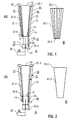
Gemäß der Erfindung berühren sich die Heizbereiche in Umfangsrichtung des Tiegels gegenseitig. Die Heizbereiche sind zu einem flächigen Widerstandsmaterial verbunden, das den Tiegel teilweise oder radial allseitig umgibt. Die Heizbereiche bilden eine Widerstandshülse (Heizfolie), die den Tiegel radial allseitig umgibt. Die Form der Widerstandshülse ist konusförmig gebildet.According to the invention, the heating areas in the circumferential direction of the crucible touch each other. The heating areas are connected to a sheet-like resistance material that surrounds the crucible partially or radially on all sides. The heating areas form a resistance sleeve (heating foil), which surrounds the crucible radially on all sides. The shape of the resistance sleeve is formed cone-shaped.
Durch eine konische Form der Widerstandshülse kann vorteilhafterweise bevorzugt ein vorderer oder hinterer Teil des Tiegels erwärmt werden. Bei konstantem Strom durch die Hülse und bei konstanter Dicke des Hülsenmaterials (z. B. 10 µm) wird die Hülse an ihrem geringsten Querschnitt am stärksten erwärmt. Diese Eigenschaft der Hülse ist ein wesentlicher Vorteil, da diese Temperaturvariation mit einzelnen Filamenten konstanten Querschnitts nicht erreichbar ist.By a conical shape of the resistance sleeve can advantageously be heated preferably a front or rear part of the crucible. With constant current through the sleeve and with a constant thickness of the sleeve material (eg 10 μm), the sleeve is heated the most at its smallest cross section. This property of the sleeve is a significant advantage, since this temperature variation with individual filaments constant cross section is not achievable.
Gemäß der Erfindung bilden die Heizbereiche einen einzigen, den Tiegel umgebenden, flächigen Heizleiter. Die hat den besonderen Vorteil, dass das flächige Widerstandsmaterial eine im Vergleich zu den einzelnen, voneinander beabstandeten Heizelementen erhöhte Stabilität aufweist. Mit der erhöhten Stabilität wird eine verbesserte Homogenität der Erwärmung des Tiegels, insbesondere bei der Elektronenstrahlheizung erzielt.According to the invention, the heating regions form a single, the crucible surrounding, flat heating element. This has the particular advantage that the sheet-like resistance material has an increased stability in comparison to the individual, spaced-apart heating elements. With the increased stability improved homogeneity of the heating of the crucible, in particular in the electron beam heating is achieved.
Gemäß der Erfindung weist das flächige Widerstandsmaterial, insbesondere die Widerstandshülse in der Axialrichtung des Tiegels eine konstante Dicke auf. Diese Variante ist insbesondere bei Verwendung einer konusförmigen Widerstandshülse von Vorteil. Die konusförmige Widerstandshülse weist eine sich von der Tiegelöffnung zum Tiegelboden verringernde Querschnittsdimension auf. Wegen der in Axial- und Azimutalrichtung konstanten Dicke des Widerstandsmaterials nimmt der integrierte Querschnitt der Widerstandshülse von der Tiegelöffnung zum Tiegelboden ab. Somit ist von der Tiegelöffnung zum Tiegelboden ein zunehmender elektrischer Widerstand gegeben (Widerstandsgradient). Daher kann in Axialrichtung des Tiegels von der Tiegelöffnung zum Tiegelboden ein Gradient der Heizleistung realisiert werden.According to the invention, the sheet-like resistance material, in particular the resistance sleeve in the axial direction of the crucible on a constant thickness. This variant is particularly advantageous when using a cone-shaped resistance sleeve. The cone-shaped resistance sleeve has a decreasing from the crucible opening to the bottom of the crucible cross-sectional dimension. Because of the thickness of the resistance material which is constant in the axial and azimuthal directions, the integrated cross-section of the resistance sleeve decreases from the crucible opening to the bottom of the crucible. Thus, from the crucible opening to Crucible bottom given an increasing electrical resistance (resistance gradient). Therefore, in the axial direction of the crucible from the crucible opening to the crucible bottom, a gradient of the heating power can be realized.
Gemäß einem bevorzugten Merkmal der Erfindung weist die Widerstandshülse an ihrem oberen Rand, der die Tiegelöffnung umgibt, und/oder an ihrem unteren Rand, der den Tiegelboden umgibt, in radialer Richtung nach außen gebogene oder geknickte Streifen auf, die zur Befestigung der Widerstandshülse jeweils entsprechend an einem oberen und/oder unteren Ringleiter und zum Ausgleich thermischer Änderungen der Länge der Widerstandshülse vorgesehen sind.According to a preferred feature of the invention, the resistance sleeve at its upper edge, which surrounds the crucible opening, and / or at its lower edge, which surrounds the crucible bottom, in the radial direction outwardly bent or kinked strips corresponding to the attachment of the resistance sleeve respectively are provided on an upper and / or lower ring conductor and to compensate for thermal changes in the length of the resistance sleeve.
Typischerweise hat der Tiegel an der Tiegelöffnung durch Abstrahlung einen stärkeren Wärmeverlust als am Tiegelboden. Dadurch entsteht bei konstanter Heizleistung ein Temperaturgradient, der in Abhängigkeit von der konkreten Anwendung, insbesondere in Abhängigkeit von dem verdampften Material unerwünscht sein kann. Die Bildung eines Gradienten der Heizleistung kann vorteilhafterweise genutzt werden, um den Temperaturgradienten zu kompensieren oder in vorbestimmter Weise einzustellen.Typically, the crucible at the crucible opening by radiation has a greater heat loss than the bottom of the crucible. As a result, a temperature gradient arises at constant heating power, which may be undesirable depending on the specific application, in particular as a function of the vaporized material. The formation of a gradient of the heating power can be advantageously used to compensate for the temperature gradient or set in a predetermined manner.
Der genannte Widerstandsgradient wirkt sich besonders vorteilhaft bei der Elektronenstrahlheizung aus. Wenn negatives Potential am oberen Ende der Widerstandshülse nahe der Tiegelöffnung anliegt, erfahren injizierte Elektronen den elektrischen Widerstand einerseits der Vakuumstrecke zum Tiegel und andererseits des Stromweges durch die Widerstandshülse. Mit dem Widerstandsgradienten kann sich das Verhältnis beider Widerstandswerte in Axialrichtung des Tiegels verändern. Nahe der Tiegelöffnung erfolgt eine stärkere Elektronenstrahlheizung als nahe dem Tiegelboden so dass der Temperaturgradient eingestellt werden kann, um die Strahlungsverluste am oberen Tiegelende zu kompensieren.The mentioned resistance gradient has a particularly advantageous effect in the case of electron beam heating. When negative potential is applied at the upper end of the resistor sleeve near the crucible opening, injected electrons experience the electrical resistance on the one hand of the vacuum path to the crucible and on the other hand of the current path through the resistor sleeve. With the resistance gradient, the ratio of both resistance values in the axial direction of the crucible can change. Close to the crucible opening there is a stronger electron beam heating than near the crucible bottom so that the temperature gradient can be adjusted to compensate for the radiation losses at the upper end of the pot.
Gemäß einer besonders bevorzugten Variante der Erfindung bilden die Heizbereiche eine Metallfolie, die sich zwischen Anschlüssen des Heizwiderstands erstreckt, die in Axialrichtung des Tiegels auf dessen Außenseite voneinander beabstandet angeordnet sind. Die Metallfolie hat vorzugsweise eine Dicke im Bereich von 5 µm bis 50 µm, insbesondere 15 µm bis 50 µm oder bevorzugt 5 µm bis 30 µm, z. B. 5 µm bis 8 µm.According to a particularly preferred variant of the invention, the heating regions form a metal foil which extends between terminals of the heating resistor, which are arranged spaced apart on the outside thereof in the axial direction of the crucible. The metal foil preferably has a thickness in the range of 5 μm to 50 μm, in particular 15 μm to 50 μm or preferably 5 μm to 30 μm, eg. B. 5 microns to 8 microns.
Gemäß einer weiteren Variante der Erfindung können der obere Ringleiter und/oder der untere Ringleiter, die oben beschrieben wurden, auch an der Widerstandshülse vorgesehen sein. Der obere Ringleiter und/oder der untere Ringleiter können z. B. an den Enden der Widerstandshülse auf deren Außenseite oder auf deren Randkante befestigt, z. B. angeschweißt sein.According to a further variant of the invention, the upper ring conductor and / or the lower ring conductor which have been described above may also be provided on the resistance sleeve. The upper ring conductor and / or the lower ring conductor can, for. B. attached to the ends of the resistance sleeve on the outside or on the edge thereof, for. B. welded.
Erfindungsgemäß können Heizbereiche, die getrennte Heizelemente umfassen, und Heizbereiche, die zu einem flächigen Widerstandsmaterial verbunden sind und den Tiegel teilweise umgeben, kombiniert werden. In diesem Fall können sich Vorteile für die Bereitstellung einer bestimmten Verteilung der Heizleistung am Tiegel ergeben.In accordance with the invention, heating areas comprising separate heating elements and heating areas connected to a sheet of resistive material and partially surrounding the crucible may be combined. In this case, there may be advantages for providing a certain distribution of heating power on the crucible.
Da die Parallelschaltung der Heizbereiche deren Halterung am Tiegel vereinfacht, kann gemäß einer weiteren Variante der Erfindung vorgesehen sein, dass der Heizwiderstand über einen elektrischen Isolator mit dem Tiegel fest verbunden ist. Der elektrische Isolator, der eine Vielzahl von Isolatorelementen oder bevorzugt einen einzigen Isolatorring umfasst, ist auf einer Außenseite des Tiegels vorzugsweise in einem Teilbereich angeordnet, in dem eine geringere Temperatur als in anderen Bereichen des Tiegels herrscht.Since the parallel connection of the heating regions simplifies their mounting on the crucible, it can be provided according to a further variant of the invention that the heating resistor is firmly connected to the crucible via an electrical insulator. The electrical insulator, which comprises a multiplicity of insulator elements or preferably a single insulator ring, is preferably arranged on an outer side of the crucible in a partial region in which a lower temperature prevails than in other regions of the crucible.
Bei Bereitstellung des unteren Ringleiters wird dieser an dem elektrischen Isolator angebracht, der mit dem Tiegel, insbesondere dem Tiegelboden fest verbunden ist. Durch die Kombination des elektrischen Isolators mit dem unteren Ringleiter wird eine zuverlässige Halterung der Heizelemente gebildet. Bei Bereitstellung des flächigen Widerstandsmaterials wird dessen unterer Rand an dem elektrischen Isolator befestigt.When providing the lower ring conductor, this is attached to the electrical insulator, which is firmly connected to the crucible, in particular the bottom of the crucible. By combining the electrical insulator with the lower ring conductor, a reliable mounting of the heating elements is formed. When providing the sheet-like resistance material whose lower edge is attached to the electrical insulator.
Vorteilhafterweise kann die thermische Belastung des elektrischen Isolators noch vermindert werden, wenn dieser an einer Halteeinrichtung des Tiegels, d.h. relativ zu der axialen Bezugsrichtung des Tiegels unterhalb des Tiegelbodens befestigt ist. Der untere Ringleiter oder der untere Rand des flächigen Widerstandsmaterials ist in diesem Fall über einen Ringhalter mit dem elektrischen Isolator verbunden. Der Ringhalter überbrückt den Abstand zwischen dem Heizwiderstand am Tiegelboden und der Position des elektrischen Isolators an der Halteeinrichtung.Advantageously, the thermal load of the electrical insulator can be reduced even further if it is applied to a holding device of the crucible, i. is fixed relative to the axial reference direction of the crucible below the bottom of the crucible. The lower ring conductor or the lower edge of the sheet resistance material is connected in this case via a ring holder with the electrical insulator. The ring holder bridges the distance between the heating resistor on the crucible bottom and the position of the electrical insulator on the holding device.
Der Ringhalter kann einen mechanischen Träger des Heizwiderstands bilden. In diesem Fall besteht er aus einem elektrisch isolierenden Material. Alternativ kann der Ringhalter eine elektrische Leitung zur Beaufschlagung des Heizwiderstands mit dem zweiten Potential bilden. In diesem Fall besteht der Ringhalter aus einem elektrisch leitfähigen Material, wobei sich der integrierte Materialquerschnitt des Ringhalters vorzugsweise von dem Durchmesser der Heizelemente oder der Dicke der Widerstandshülse so unterscheidet, dass bei der Widerstandsheizung ein geringer elektrischer Widerstand und somit praktisch keine Aufheizung und bei der Elektronenstrahlheizung praktisch keine Elektronenemission realisiert werden. Der Ringhalter kann z. B. einen Ring aus einer Metallfolie oder einem Blech, Haltestifte oder Stanz- oder Frästeile umfassen.The ring holder can form a mechanical support of the heating resistor. In this case it consists of an electrically insulating material. Alternatively, the ring holder can form an electrical line for acting on the heating resistor with the second potential. In this case, the ring holder consists of an electrically conductive material, wherein the integrated material cross section of the ring holder preferably differs from the diameter of the heating elements or the thickness of the resistance sleeve so that in the resistance heating a low electrical resistance and thus virtually no heating and the electron beam heating virtually no electron emission can be realized. The ring holder can, for. B. a ring of a metal foil or a sheet metal, holding pins or stamped or milled parts.
Die Bereitstellung des elektrischen Isolators an der Halteeinrichtung hat den Vorteil, dass die Halteeinrichtung nicht nur von der indirekten Heizung ausgenommen ist, sondern sogar aktiv direkt gekühlt werden kann, so dass eine unerwünschte thermische Beanspruchung des elektrischen Isolators ausgeschlossen wird.The provision of the electrical insulator on the holding device has the advantage that the holding device is not only excluded from the indirect heating, but can even be actively cooled directly, so that an undesirable thermal stress of the electrical insulator is excluded.
Gemäß einer weiteren vorteilhaften Variante der Erfindung weist die Verdampferzelle eine Abschirmeinrichtung mit einer Abschirmwand auf, die den Tiegel in radialer Richtung umgibt. Die Abschirmwand kann vorteilhafterweise mehrere Funktionen erfüllen. Erstens kann eine thermische Abschirmung der Umgebung der Verdampferzelle realisiert werden, was insbesondere für die unabhängige Steuerung von mehreren benachbarten Verdampferzellen in einer Beschichtungsanlage von Vorteil ist. Zweitens kann die Abschirmwand einen mechanischen Träger für die Heizeinrichtung, insbesondere der Heizbereiche und ggf. einen der Ringleiter bilden.According to a further advantageous variant of the invention, the evaporator cell has a shielding device with a shielding wall which surrounds the crucible in the radial direction. The shield can advantageously fulfill several functions. First, a thermal shielding of the environment of the evaporator cell can be realized, which is particularly advantageous for the independent control of several adjacent evaporator cells in a coating plant. Secondly, the shielding wall can form a mechanical support for the heating device, in particular the heating areas and possibly one of the ring conductors.
Ein besonderer Vorteil der Erfindung ergibt sich daraus, dass die Heizbereiche mit einem Ende, vorzugsweise mit dem oberen Ende, d.h. in der Umgebung der Tiegelöffnung mit der Abschirmwand elektrisch verbunden sein können. Im Unterschied zu der herkömmlichen Verdampferzelle ist ein elektrischer Isolator im oberen Bereich des Tiegels, insbesondere in der Umgebung der Tiegelöffnung nicht erforderlich. Über die Abschirmwand kann die elektrische Verbindung der oberen Enden der Heizbereiche (ggf. mit dem oberen Ringleiter) mit einem Pol der Stromquelle oder Hochspannungsquelle hergestellt werden. Die Heizbereiche (ggf. der obere Ringleiter oder der obere Rand des flächigen Widerstandsmaterials) können direkt an der Abschirmwand befestigt sein. Damit wird der Aufbau der erfindungsgemäßen Verdampferzelle erheblich vereinfacht.A particular advantage of the invention results from the fact that the heating regions can be electrically connected to the shielding wall with one end, preferably with the upper end, ie in the vicinity of the crucible opening. In contrast to the conventional evaporator cell, an electrical insulator is not required in the upper region of the crucible, in particular in the vicinity of the crucible opening. About the shield, the electrical connection of the upper ends of the heating areas (possibly with the upper ring conductor) can be made with a pole of the power source or high voltage source. The heating areas (if necessary, the upper ring conductor or the upper edge of the sheet resistance material) can directly be attached to the shield. Thus, the structure of the evaporator cell according to the invention is considerably simplified.
Gemäß einer weiteren vorteilhaften Variante der Erfindung können die Heizbereiche so angeordnet sein, dass der radiale Abstand der oberen Enden der Heizbereiche vom Tiegel, insbesondere von der Tiegelöffnung größer ist als der radiale Abstand der unteren Enden der Heizbereiche vom Tiegel, insbesondere vom Tiegelboden. Der radiale Abstand der oberen Enden der Heizbereiche von der Tiegelöffnung ist vorzugsweise im Bereich von 1 mm bis 6 mm gewählt. Der radiale Abstand der unteren Enden der Heizbereiche vom Tiegelboden ist vorzugsweise im Bereich von 1 mm bis 4 mm gewählt.According to a further advantageous variant of the invention, the heating regions can be arranged so that the radial distance of the upper ends of the heating regions from the crucible, in particular from the crucible opening is greater than the radial distance of the lower ends of the heating regions from the crucible, in particular from the crucible bottom. The radial distance of the upper ends of the heating regions from the crucible opening is preferably selected in the range of 1 mm to 6 mm. The radial distance of the lower ends of the heating regions from the crucible bottom is preferably selected in the range of 1 mm to 4 mm.
Mit Heizbereichen, die sich in Längsrichtung gerade erstrecken, ergibt sich ein Abstandsgradient von der Tiegelöffnung hin zum Tiegelboden. Durch den abnehmenden radialen Abstand sinkt der Widerstand der Vakuumstrecke von den Heizbereichen zur Seitenwand des Tiegels. Damit kann vorteilhafterweise das oben genannte Verhältnis der Widerstandswerte über die Vakuumstrecke und durch die Heizbereiche zusätzlich beeinflusst werden, um den Temperaturgradienten in Axialrichtung zu kompensieren oder einzustellen und/oder die Temperatur-Emissionsregelung zu beeinflussen.With heating regions that extend straight in the longitudinal direction, a distance gradient results from the crucible opening towards the bottom of the crucible. Due to the decreasing radial distance, the resistance of the vacuum path decreases from the heating areas to the side wall of the crucible. Thus, advantageously, the abovementioned ratio of the resistance values across the vacuum path and through the heating regions can be additionally influenced in order to compensate or adjust the temperature gradient in the axial direction and / or to influence the temperature emission control.
Alternativ kann vorgesehen sein, dass der Heizwiderstand bei der Tiegelöffnung einen geringeren radialen Abstand von der Seitenwand aufweist als bei dem Tiegelboden. Vorteilhafterweise kann damit die Heizleistung nahe dem Tiegelboden im Vergleich zur Heizleistung nahe der Tiegelöffnung verringert werden.Alternatively, it can be provided that the heating resistor has a smaller radial distance from the side wall in the case of the crucible opening than in the crucible bottom. Advantageously, thus the heating power can be reduced near the bottom of the crucible compared to the heating power near the crucible opening.
Zusätzlich zu dem Abstandsgradienten ist gemäß der Erfindung ein Widerstandsgradient vorgesehen, mit dem der Ohm'sche Widerstand der Heizbereiche bei der Tiegelöffnung geringer als beim Tiegelboden ist. Der Widerstandsgradient wird wie oben beschrieben durch die Konusform des Heizwiderstands erhalten.In addition to the distance gradient, a resistance gradient is provided according to the invention, with which the ohmic resistance the heating areas at the pot opening is less than the bottom of the pot. The resistance gradient is obtained as described above by the cone shape of the heating resistor.
Es kann vorgesehen sein, dass der Heizwiderstand bei der Tiegelöffnung einen größeren Widerstandswert aufweist als bei dem Tiegelboden. Vorteilhafterweise ist damit eine weitere Möglichkeit gegeben, bei Bedarf die Heizleistung nahe dem Tiegelboden kleiner einzustellen als die Heizleistung nahe der Tiegelöffnung.It can be provided that the heating resistor has a greater resistance value at the crucible opening than at the crucible bottom. Advantageously, this provides a further possibility, if necessary, to set the heating power close to the bottom of the crucible smaller than the heating power close to the crucible opening.
Besonders bevorzugt ist eine Variante der Erfindung, bei der sich die Heizbereiche, insbesondere die Heizelemente zwischen dem oberen Ringleiter und dem unteren Ringleiter oder das flächige Widerstandsmaterial, freitragend erstrecken. Dabei kann der untere Ringleiter oder der untere Rand des flächigen Widerstandsmaterials unmittelbar oder über die genannten Haltestifte am elektrischen Isolator befestigt sein, der am Tiegelboden oder der Halteeinrichtung angeordnet ist, während der obere Ringleiter oder der obere Rand des flächigen Widerstandsmaterials in der Umgebung der Tiegelöffnung an der Innenseite der Abschirmwand befestigt sein kann. Bei einem zylindrischen Aufbau mit einem Tiegel in Form eines geraden Zylinders und einer Abschirmwand in Form einer geraden, zylinderförmigen Hülse wird somit der genannte Abstandsgradient mit dem in Verdampfungsrichtung zunehmenden radialen Abstand der Heizelemente vom Tiegel realisiert.Particularly preferred is a variant of the invention in which the heating areas, in particular the heating elements between the upper ring conductor and the lower ring conductor or the sheet-like resistance material, extend cantilevered. In this case, the lower ring conductor or the lower edge of the sheet resistance material can be attached directly or via said retaining pins on the electrical insulator, which is arranged on the crucible bottom or the holding device, while the upper ring conductor or the upper edge of the sheet resistance material in the vicinity of the crucible opening the inside of the shield can be attached. In a cylindrical construction with a crucible in the form of a straight cylinder and a shielding wall in the form of a straight, cylindrical sleeve, said spacing gradient is thus realized with the radial spacing of the heating elements from the crucible increasing in the direction of evaporation.
Gemäß einer weiteren vorteilhaften Variante der Erfindung ist die Verdampferzelle mit mindestens einer Temperaturmesseinrichtung ausgestattet, mit der eine Betriebstemperatur der Verdampferzelle erfassbar ist. Dies bietet insbesondere den Vorteil, dass die Temperaturmessung einfach für verschiedene Messprinzipien eingerichtet werden kann. Vorzugsweise umfasst die Temperaturmesseinrichtung ein Thermoelement, ein Bolometerelement und/oder ein Pyrometerelement. Das Thermoelement hat den Vorteil einer unmittelbaren und kostengünstigen Temperaturmessung, während die optische Temperaturmessung mit Pyrometer- oder Bolometerelementen Vorteile in Bezug auf die berührungslose Messung über relativ große Messabstände haben.According to a further advantageous variant of the invention, the evaporator cell is equipped with at least one temperature measuring device with which an operating temperature of the evaporator cell can be detected. This offers the particular advantage that the temperature measurement can be easily set up for different measuring principles. Preferably comprises the temperature measuring device is a thermocouple, a bolometer element and / or a pyrometer element. The thermocouple has the advantage of a direct and cost-effective temperature measurement, while the optical temperature measurement with pyrometer or bolometer elements have advantages in terms of non-contact measurement over relatively large measuring distances.
Wegen der einfachen Kalibrierbarkeit und des geringen Platzbedarfs wird jedoch das Thermoelement zur Temperaturmessung bevorzugt. In dem interessierenden Bereich hoher Temperaturen sind Thermoelemente, insbesondere auf der Basis von Wolfram und Rhenium verfügbar (siehe z. B.
Wenn gemäß einer weiteren Variante der Erfindung das Thermoelement mit einem axialen Abstand unterhalb des Tiegelbodens in der axialen Bezugsrichtung des Tiegels verschiebbar ist, können mehrere Vorteile erzielt werden. Erstens kann durch eine einfache Verschiebung der axiale Abstand des Thermoelements vom Tiegelboden eingestellt und damit an die konkreten Betriebsbedingungen der Verdampferzelle angepasst werden. Des weiteren kann das Thermoelement, z. B. für Zwecke der Wartung oder des Austauschs leicht von der Verdampferzelle entfernt werden, ohne dass eine aufwendige Demontage erforderlich ist. Hierzu weist das Thermoelement vorzugsweise eine gerade Bauform auf. Dies ermöglicht, dass das Thermoelement durch einen geraden Kanal durch die Halteeinrichtung des Tiegels und ggf. weitere Komponenten der Verdampferzelle bis zur gewünschten Position unterhalb des Tiegelbodens vorgeschoben werden kann. Der optimale axiale Abstand vom Tiegelboden kann zum Beispiel durch Testreihen oder durch eine vorherige Kalibrierungsmessung ermittelt werden.If according to a further variant of the invention, the thermocouple is displaceable with an axial distance below the crucible bottom in the axial reference direction of the crucible, several advantages can be achieved. First, the axial distance of the thermocouple from the bottom of the crucible can be adjusted by a simple displacement and thus adapted to the specific operating conditions of the evaporator cell. Furthermore, the thermocouple, z. B. for purposes of maintenance or replacement easily be removed from the evaporator cell, without a costly disassembly is required. For this purpose, the thermocouple preferably has a straight design. This allows the thermocouple through a straight channel through the holding device of the crucible and possibly other components of the evaporator cell to the desired Position can be advanced below the bottom of the crucible. The optimal axial distance from the crucible bottom can be determined, for example, by test series or by a previous calibration measurement.
Gemäß einer weiteren vorteilhaften Merkmal der Erfindung ist die Halteeinrichtung der Verdampferzelle zur thermisch isolierten Positionierung des Tiegels relativ zu den anderen Teilen der Verdampferzelle und insbesondere relativ zu einem Träger eingerichtet. Die Halteeinrichtung stellt eine mechanische Halterung dar, welche die äußere Oberfläche des Tiegels im Wesentlichen freilässt, wenn dieser aus einem elektrisch leitfähigen Material gebildet ist. Vorzugsweise ist die Halteeinrichtung in diesem Fall am Tiegelboden vorgesehen, so dass die Seitenwände des Tiegels für die Wärmeübertragung von der Heizeinrichtung freiliegen. Wenn die Halteeinrichtung aus einem elektrisch leitfähigen Material besteht, kann sie vorteilhafterweise neben der mechanischen Halterung gleichzeitig als Hochspannungskontakt für den Tiegel dienen. Wenn der Tiegel aus einem elektrisch nicht leitfähigen Material besteht, ist die Halteeinrichtung so geformt, dass sie den größten Teil der Außenfläche des Tiegels überdeckt. In diesem Fall ist vorzugsweise eine formschlüssige Verbindung zwischen der Außenfläche des Tiegels und der Innenseite der Halteeinrichtung vorgesehen.According to a further advantageous feature of the invention, the holding device of the evaporator cell for the thermally insulated positioning of the crucible is arranged relative to the other parts of the evaporator cell and in particular relative to a carrier. The holding device is a mechanical holder, which leaves the outer surface of the crucible substantially free, if it is formed of an electrically conductive material. Preferably, the holding device is provided in this case on the bottom of the crucible, so that the side walls of the crucible for heat transfer from the heater are exposed. If the holding device consists of an electrically conductive material, it can advantageously serve in addition to the mechanical support at the same time as a high voltage contact for the crucible. If the crucible is made of an electrically non-conductive material, the holding device is shaped so that it covers most of the outer surface of the crucible. In this case, a positive connection between the outer surface of the crucible and the inside of the holding device is preferably provided.
Wenn die Halteeinrichtung durch ein Bauteil mit einem Hohlprofil gebildet wird, können sich Vorteile für die Verminderung der Wärmeleitung vom Tiegel zur Umgebung und für eine stabile Positionierung des Tiegels auch bei extrem hohen Temperaturen ergeben. Die Halteeinrichtung ist bspw. ein Hohlzylinder oder ein Hohlkonus, der an der Unterseite des Tiegels angebracht ist. Die zylinder- oder konusförmige Halteeinrichtung weist eine besonders hohe mechanische Stabilität auf. Der Tiegel wird steif und vollflächig mit einem Schutz gegen Torsion und Verbiegung gehalten.If the holding device is formed by a component with a hollow profile, there may be advantages for the reduction of the heat conduction from the crucible to the environment and for a stable positioning of the crucible even at extremely high temperatures. The holding device is, for example, a hollow cylinder or a hollow cone, which is attached to the underside of the crucible. The cylindrical or conical holding device has a particularly high mechanical stability. The crucible is held stiff and full surface with protection against torsion and bending.
Vorteilhafterweise wird durch das Hohlprofil, das den Hochspannungskontakt des Tiegels bildet, in unmittelbarer Umgebung des Tiegels ein Raum geschaffen, in dem die Betriebstemperatur des Tiegels messbar ist und in dem eine reduzierte Feldstärke gegeben ist. Daher ist die Temperaturmesseinrichtung vorzugsweise zur Temperaturmessung im Inneren der Halteeinrichtung vorgesehen. Die Halteeinrichtung weist zum Beispiel eine axiale Öffnung auf, durch welche das Thermoelement in die Halteeinrichtung einführbar ist. Die Positionierung des Thermoelements im Hohlprofil der Halteeinrichtung hat den besonderen Vorteil, dass eine allseitige Abschirmung des Thermoelements insbesondere gegen die hohen Feldstärken beim Betrieb der Heizeinrichtung als Elektronenstrahlheizung erreicht wird und unerwünschte Hochspannungsüberschläge vermieden werden.Advantageously, a space is created by the hollow profile forming the high voltage contact of the crucible in the immediate vicinity of the crucible, in which the operating temperature of the crucible is measurable and in which a reduced field strength is given. Therefore, the temperature measuring device is preferably provided for measuring the temperature in the interior of the holding device. The holding device has, for example, an axial opening through which the thermocouple can be inserted into the holding device. The positioning of the thermocouple in the hollow profile of the holding device has the particular advantage that an all-round shielding of the thermocouple is achieved in particular against the high field strengths in the operation of the heater as electron beam heating and unwanted high voltage flashovers are avoided.
Vorzugsweise ist an dem Träger eine Aufnahme vorgesehen, in welche die Halteeinrichtung einsteckbar ist. Die Aufnahme besitzt bspw. die Form eines zylinder- oder konusförmigen Schachtes, dessen Innenform an die Außenform des Hohlprofils der Halteeinrichtung angepasst ist. Vorteilhafterweise bildet die eingesteckte Halteeinrichtung einen festen mechanischen Kontakt mit dem Träger, so dass ein Verkippen des Tiegels während des Betriebes der Verdampferzelle vermieden wird.Preferably, a receptacle is provided on the carrier, in which the holding device can be inserted. The receptacle has, for example, the shape of a cylindrical or conical shaft whose inner shape is adapted to the outer shape of the hollow profile of the holding device. Advantageously, the inserted holding device forms a firm mechanical contact with the carrier, so that tilting of the crucible during operation of the evaporator cell is avoided.
Vorteilhafterweise ermöglicht die erfindungsgemäße Verdampferzelle eine genaue Temperatureinstellung im Tiegel. Hierzu ist vorzugsweise eine Regeleinrichtung vorgesehen, mit der die Heizeinrichtung einstellbar ist. Die Regeleinrichtung kann die folgenden Regelkreise enthalten. Ein erster Regelkreis dient der Einstellung eines Heizstroms des Heizwiderstandes für einen Widerstandsheizbetrieb. Der zweite Regelkreis dient der Einstellung eines Elektronenstroms vom Heizwiderstand zum Tiegel für einen Elektronenstrahl-Heizbetrieb.Advantageously, the evaporator cell according to the invention enables a precise temperature adjustment in the crucible. For this purpose, a control device is preferably provided, with which the heating device is adjustable. The controller may include the following control circuits. A first control circuit is used to set a heating current of the heating resistor for a resistance heating operation. The second control circuit is used to set an electron current from the heating resistor to the crucible for an electron beam heating operation.
In den Regelkreisen wird der Heiz- und/oder Elektronenstrom des Heizwiderstandes allgemein unter Verwendung einer Istgröße geregelt, die in Abhängigkeit von der konkreten Aufgabe der Verdampferzelle gewählt ist. Beispielsweise kann eine gemessene Aufdampfrate als Istgröße für die Regelkreise verwendet werden. Bevorzugt erfolgt die Regelung in Abhängigkeit von der Betriebstemperatur des Tiegels. Hierzu ist die Temperaturmesseinrichtung mit wenigstens einem der Regelkreise verbunden.In the control circuits, the heating and / or electron current of the heating resistor is generally controlled using an actual variable that is selected as a function of the specific task of the evaporator cell. For example, a measured vapor deposition rate can be used as the actual variable for the control circuits. The regulation preferably takes place as a function of the operating temperature of the crucible. For this purpose, the temperature measuring device is connected to at least one of the control circuits.
Weitere Vorteile werden mit einer Ausführungsform der Erfindung erzielt, bei der die Regeleinrichtung einen einzigen Regelkreis aufweist, mit dem die Temperatur der Verdampferzelle einstellbar ist. Besonders bevorzugt ist der einzige Regelkreis für eine Spannungsregelung der Heizeinrichtung vorgesehen. Mit dem Regelkreis wird in Abhängigkeit von einer IstGröße, z. B. der Temperatur, die mit der Temperaturmesseinrichtung ermittelt wurde, die Spannung an den Enden der parallel geschalteten Heizelemente eingestellt. Vorteilhafterweise wird die Verdampferzelle ausschließlich über die Heizspannung der Parallelschaltung der Heizelemente geregelt.Further advantages are achieved with an embodiment of the invention in which the control device has a single control circuit with which the temperature of the evaporator cell is adjustable. Particularly preferably, the single control loop is provided for a voltage regulation of the heating device. The control loop is dependent on an IstGröße, z. B. the temperature which was determined with the temperature measuring device, the voltage at the ends of the parallel heating elements. Advantageously, the evaporator cell is controlled exclusively by the heating voltage of the parallel connection of the heating elements.
Die Erfinder haben festgestellt, dass durch die Parallelschaltung der Heizelemente erreicht wird, dass bei einer ausreichend hohen Heizspannung, vorzugsweise im Bereich von 2 V bis 8 V, z. B. bei 4 V automatisch der Übergang von der Widerstandsheizung zur Elektronenstrahlheizung erfolgt, wobei die Leistung der Elektronenstrahlheizung passiv und mit hoher Stabilität dem Verlauf der Heizspannung folgt. Im Unterschied zur Regelung der herkömmlichen Verdampferzelle ist es nicht erforderlich, die Hochspannungsquelle zu regeln. Es wurde festgestellt, dass die Hochspannungsquelle bei Regelung der Heizspannung der Heizelemente selbst nachführend arbeitet. Überraschenderweise wurde mit dem einen Regelkreis selbst bei gleichzeitigem Widerstands- und Elektronenstrahlheizbetrieb keine oszillierende, sondern eine stabile Regelcharakteristik beobachtet.The inventors have found that is achieved by the parallel connection of the heating elements, that at a sufficiently high heating voltage, preferably in the range of 2 V to 8 V, z. B. at 4 V, the transition from the resistance heating to the electron beam heating automatically, the performance of the electron beam heating passively and with high stability follows the course of the heating voltage. Unlike the regulation of the conventional evaporator cell, it is not required to regulate the high voltage source. It has been found that the high voltage source itself operates to control the heating voltage of the heating elements. Surprisingly, with the one control circuit even with simultaneous resistance and Elektronenstrahlheizbetrieb no oscillating, but a stable control characteristic observed.
Die bevorzugte Regelcharakteristik der Elektronenstrahlheizung zeichnet sich durch eine Temperatur-Emissionsregelung aus, bei der mit steigender Temperatur der Heizbereiche der Widerstand der Vakuumstrecke zum Tiegel stetig sinkt. Der Elektronenstrom über die Vakuumstrecke steigt mit steigender Temperatur der Heizbereiche kontinuierlich an. Hierzu im Gegensatz wäre mit einer Feld-Emissionsregelung ein sprunghafter Anstieg des Elektronenstroms gegeben. Die Temperatur-Emissionsregelung wird mit einer Beschleunigungsspannung, für die bei der gegebenen Länge der Vakuumstrecke eine FeldEmission ausgeschlossen ist (z. B. U < 500 V), und einem ausreichend hohen Elektronenstrom, bei dem die Temperatur-Emission erfolgt (z. B. I = 1 A bis 3 A), der Elektronenstrahlheizung erzielt.The preferred control characteristic of electron beam heating is characterized by a temperature emission control in which the resistance of the vacuum path to the crucible drops steadily as the temperature of the heating regions rises. The electron flow through the vacuum line increases continuously with increasing temperature of the heating areas. In contrast, with a field emission control, there would be a sudden increase in the electron current. The temperature emission control is precluded by an acceleration voltage for which a field emission is excluded for the given length of the vacuum path (eg U <500 V), and a sufficiently high electron flow at which the temperature is emitted (eg. I = 1 A to 3 A), which achieves electron beam heating.
Als besonders vorteilhaft hat es sich erwiesen, wenn der Tiegel und der Heizwiderstand der erfindungsgemäßen Verdampferzelle, und vorzugsweise auch die Abschirmwand der Abschirmeinrichtung vollständig aus Tantal bestehen. Obwohl Tantaloxid einen relativ niedrigen Schmelzpunkt und einen relativ hohen Dampfdruck hat, konnten die Erfinder überraschenderweise feststellen, dass selbst im Hochtemperaturbetrieb der Verdampferzelle keinerlei unerwünschtes Tantal in Schichten gefunden wurde, die mit der Verdampferzelle hergestellt wurden.It has proved to be particularly advantageous if the crucible and the heating resistor of the evaporator cell according to the invention, and preferably also the shielding wall of the shielding device, consist entirely of tantalum. Although tantalum oxide has a relatively low melting point and a relatively high vapor pressure, the inventors surprisingly found that even in the high temperature operation of the evaporator cell, no undesirable tantalum was found in layers made with the evaporator cell.
Eine Beschichtungsanlage kann mit mindestens einer erfindungsgemäßen Verdampferzelle ausgestattet sein.A coating system may be equipped with at least one evaporator cell according to the invention.
Im Gegensatz zu herkömmlichen Elektronenstrahlverdampfern, bei denen typischerweise flache Tiegel vorgesehen sind, kann die Verdampferzelle in der Beschichtungsanlage mit einem relativ zur Vertikalen schräg oder sogar horizontal ausgerichteten Tiegel angeordnet sein.In contrast to conventional electron beam evaporators, in which flat crucibles are typically provided, the evaporator cell can be arranged in the coating installation with a crucible oriented obliquely or even horizontally relative to the vertical.
Weitere Einzelheiten und Vorteile der Erfindung werden im Folgenden unter Bezugnahme auf die beigefügten Zeichnungen erläutert. Es zeigen:
- Figuren 1A und 1B:
- schematische Ansichten einer Verdampferzelle (keine Ausführungsform der Erfindung);
- Figuren 2A und 2B:
- schematische Ansichten einer bevorzugten Ausführungsform der erfindungsgemäßen Verdampferzelle;
- Figuren 3A und 3B:
- schematische Ansichten weiterer Varianten der erfindungsgemäßen Verdampferzelle;
- Figur 4:
- die erfindungsgemäße Kombination der Verdampferzelle mit einer Regeleinrichtung;
- Figur 5:
- eine Kurvendarstellungen zur Illustration verschiedener Betriebszustände der erfindungsgemäßen Verdampferzelle; und
- Figuren 6A bis 6C:
- Einzelheiten einer weiteren Ausführungsform einer erfindungsgemäßen Verdampferzelle.
- FIGS. 1A and 1B:
- schematic views of an evaporator cell (not an embodiment of the invention);
- FIGS. 2A and 2B:
- schematic views of a preferred embodiment of the evaporator cell according to the invention;
- FIGS. 3A and 3B:
- schematic views of further variants of the evaporator cell according to the invention;
- FIG. 4:
- the inventive combination of the evaporator cell with a control device;
- FIG. 5:
- a graphs illustrating various operating conditions of the evaporator cell according to the invention; and
- FIGS. 6A to 6C:
- Details of a further embodiment of an evaporator cell according to the invention.
Die in
Der Tiegel 10 zur Aufnahme von Verdampfungsgut mit einem Tiegelboden 11, einer umlaufenden Seitenwand 12 und einer Austrittsöffnung 13 weist eine Konusform mit einem sich vom Tiegelboden 11 zur Austrittsöffnung 13 vergrößernden Durchmesser auf. Der Tiegel 10 besteht aus einem ein- oder mehrlagigen Material, das bis zu einer Temperatur von 3000 °C formbeständig und mechanisch stabil ist. Der Tiegel 10 kann vollständig aus einem Metallblech oder aus einer Zusammensetzung mit einem nicht-elektrisch leitfähigen Grundkörper und einer metallischen Beschichtung bestehen, wobei zum Verdampferbetrieb der elektrisch leitfähige Teil des Tiegels 10 jeweils mit einer Hochspannungsquelle 24 (siehe
Die Temperaturmesseinrichtung 30 umfasst ein Thermoelement 31, dessen Kontaktstelle unterhalb des Tiegelbodens 11 angeordnet und mit einem Messwandler 32 verbunden ist. Das Thermoelement ist bspw. ein Wolfram-Rhenium-Thermoelement, wie es in der o. g. Publikation von R. R. Asamoto et al. beschrieben ist. Der Messwandler 32 ist bspw. vom Typ "Eurotherm 2604".The
Die Halteeinrichtung 40 umfasst einen Hohlzylinder 41 aus einem temperaturbeständigen Material, z. B. Tantal mit einem axial verlaufenden Kanal 47. Durch den Kanal 47 kann das Thermoelement 31 elektrisch isoliert durch das Innere des Hohlzylinders 41 eingeführt werden. Das Thermoelement 31 ist im Kanal 44 verschiebbar, so dass der axiale Abstand X vom Tiegelboden einstellbar ist. Der axiale Abstand X wird z. B. im Bereich von 2 mm bis 15 mm eingestellt.The holding
Der untere Rand des Hohlzylinders 41 ist mit einem Träger 42 verbunden, der ortsfest oder verstellbar in einer Beschichtungsanlage angeordnet ist. Der Träger 42 enthält eine ringförmige Aufnahme 43, in welcher der untere Rand des Hohlzylinders 41 befestigt ist. Die Halteeinrichtung 40 dient der stabilen Halterung und als elektrischer Hochspannungskontakt des Tiegels 10.The lower edge of the
Die Halteeinrichtung 40 stellt eine thermische Isolation zwischen dem Tiegel 10 und den übrigen Teilen an der Beschichtungsanlage dar. Zur Minimierung der Wärmeleitung besteht der Hohlzylinder 41 aus einem Blech mit einer Dicke unterhalb von 500 µm, vorzugsweise kleiner als 200 µm, z. B. im Bereich von 50 µm bis 200 µm.The holding
Die Abschirmeinrichtung 50 umfasst eine seitlich umlaufende Abschirmwand 51 und eine Abschirmkappe 52. Die Abschirmwand 51 stellt eine thermische Barriere nach außen und eine mechanische Halterung für den oberen Ringleiter 22.1 der Heizeinrichtung 20 dar. Sie besteht z. B. aus Ta-Blech mit einer Dicke von 50 µm oder mehreren Lagen einer Ta-Folie. Die Abschirmkappe 52 dient der thermischen Isolation zwischen der Verdampferzelle 100 und einem zu beschichtenden Substrat. Mit der Abschirmkappe 52 wird der Spalt zwischen dem Tiegel 10 und der Abschirmwand 51, in dem die Heizelemente 21.1 angeordnet sind, hin zum Substrat abgeschirmt. In der Mitte der Abschirmkappe 52 ist eine Öffnung vorgesehen, die den Dampfstrahl aus dem Tiegel 10 zum Substrat durchlässt. Die Öffnung wird je nach Anwendung möglichst klein gewählt (z. B. 15 mm), um die Homogenität der Temperaturverteilung im Tiegel 10 zu verbessern und die erforderliche Heizleistung zu minimieren.The shielding
Die Heizelemente 21.1 der Heizeinrichtung 20, die den Heizwiderstand 21 bilden, sind getrennte Heizleiter, die sich zwischen einem oberen Ringleiter 22.1 und einem unteren Ringleiter 22.2 erstrecken (siehe schematische Seitenansicht in Figur 1B). Des Weiteren ist eine Anschlussleitung 22.3 vorgesehen, die mit der Heizstromquelle 23 (siehe
Gemäß einer abgewandelten Variante können die Heizelemente durch gekrümmte Widerstandsdrähte gebildet werden. Alle Widerstandsdrähte weisen in diesem Fall die gleiche Krümmung auf, so dass die Heizelemente mit gegenseitigen Abständen zwischen den oberen und unteren Ringleitern 22.1, 22.2 parallel angeschlossen werden können. Gekrümmte Heizelemente können zum Beispiel eine periodische Struktur, wie zum Beispiel eine Wellen-, Dreieck- oder Spiral-Struktur oder eine zwischen den oberen und unteren Ringleitern 22.1, 22.2 sich erstreckende Bogenstruktur aufweisen.According to a modified variant, the heating elements can be formed by curved resistance wires. All resistance wires have the same curvature in this case on, so that the heating elements with mutual distances between the upper and lower ring conductors 22.1, 22.2 can be connected in parallel. Curved heating elements may, for example, have a periodic structure such as a wave, triangle or spiral structure or an arch structure extending between the upper and lower ring conductors 22.1, 22.2.
Die Heizelemente 21.1 sind auf der Außenseite der Seitenwand 12 mit einem radialen Abstand von deren Oberfläche angeordnet. Der radiale Abstand wird durch die Dimensionen der oberen und unteren Ringleiter 22.1, 22.2 und deren Befestigung einerseits an der Abschirmeinrichtung 50 und andererseits am Tiegel 10 bestimmt.The heating elements 21.1 are arranged on the outside of the
Der obere Ringleiter 22.1 ist über radial außerhalb der Heizelemente 21.1 und innerhalb der Abschirmeinrichtung 50 verlaufende Stäbe (siehe z. B. 21.3) am Isolator 14, am Träger 42 oder einem anderen ortsfesten Teil der Beschichtungsanlage befestigt (siehe auch
Die Abschirmeinrichtung 50 ist an einem elektrisch isolierenden Teil des Trägers 42 oder einem anderen ortsfesten Teil einer Beschichtungsanlage (nicht dargestellt) befestigt. Die Abschirmwand 51 kann auf den Stäben 21.3 aufsitzen, die einen Rahmen oder ein Gerüst für die Abschirmeinrichtung 50 bilden. Die Abschirmeinrichtung 50 kann zusätzlich einen äußeren Kühlschild (nicht dargestellt) aufweisen, der z. B. einen mit flüssigem Stickstoff oder Wasser gekühlten Doppelmantel umfasst. Da der obere Ringleiter 22.1 einen Abstand von der Seitenwand 12 und der Tiegelöffnung 13 aufweist, ist der Tiegel 10 frei stehend ausschließlich auf der Halteeinrichtung 40 befestigt. Der obere Ringleiter 22.1 besteht zum Beispiel aus einem gebogenen Draht (Torus) aus Tantal mit einem Durchmesser von 2 mm oder einem ringförmigen Tantalblech mit einer Dicke von 1 mm.The shielding
Der untere Ringleiter 22.2 ist auf einem ringförmigen Isolator 14 befestigt, der den Tiegel 10 am Tiegelboden 11 umgibt. Der Isolator 14 ist an der Seitenwand 12 oder einem abgewinkelten Teilbereich der Abschirmwand 51 befestigt. Die Befestigung wird zum Beispiel durch Bornitrid gebildet. Der Isolator 14 enthält eine Durchgangsöffnung zur Aufnahme der Anschlussleitung 22.3, die mit dem unteren Ringleiter 22.2 verbunden ist. Der untere Ringleiter 22.2 besteht ebenfalls aus Tantal in Form eines gebogenen Drahtes (Torus) oder ringförmigen Bleches. Die Heizelemente 21.1 sind mittels einer Schweißverbindung am unteren Ringleiter 22.2 befestigt. Der Isolator 14 besteht z. B. aus Bornitrid, Saphir oder Quartz.The lower ring conductor 22. 2 is fastened on an
Die in
Wie mit der schematischen Seitenansicht in
Die Haltestifte 15, die die Widerstandshülse 21.2 tragen, sind auf dem ringförmigen Isolator 14 befestigt. Es sind beispielsweise zwei oder mehr Haltestifte 15 vorgesehen, die aus einem elektrisch isolierenden Material, z. B. Bornitrid (insbesondere pyrolytisch abgeschiedenes Bornitrid, PBN, oder aus einem elektrisch leitfähigen Material, z. B. Tantal oder Wolfram bestehen. Einer der Haltestifte 15 kann als elektrische Verbindung der konusförmigen Hülse 21.2 mit der Anschlussleitung 22.3 verwendet werden.The retaining pins 15, which carry the resistance sleeve 21.2, are mounted on the
Die in
Vorteilhafterweise verbessert die Befestigung des oberen Randes der Widerstandshülse 21.2 über die Streifen 21.4 den Ausgleich thermischer Änderungen der Länge der Widerstandshülse 21.2. Wenn sich die Länge der Widerstandshülse 21.2 im heißen Zustand z. B. um bis zu zwei Millimeter gegenüber dem kalten Zustand vergrößert, kann diese Längenänderung durch die Streifen 21.4 aufgenommen werden. Somit kann eine unerwünschte thermisch-mechanische Überbeanspruchung der Widerstandshülse 21.2, wie z. B. eine Stauchung oder Verformung, oder sogar deren Abriss vom Ringleiter sicher vermieden werden. Der Ringleiter kann einen im Vergleich zu
Gemäß
Gemäß
Gemäß einer weiteren Ausführungsform der Erfindung kann die Widerstandshülse 21.2 an ihrem unteren Ende, d. h. in der Umgebung des Tiegelbodens Einschnitte aufweisen, durch die in Umfangsrichtung der Widerstandshülse 21.2 biegsame Streifen gebildet werden, wie dies oben unter Bezug auf die
Die Einstellung des Betriebsstroms der Heizeinrichtung 20 erfolgt mit einer schematisch in
Die Hochspannungsquelle 24 ist ein Gleichspannungs-Netzteil mit einem Ausgangsstrom z. B. bis zu 10 A und einer Ausgangsspannung z. B. bis zu 500 V. Aus Kostengründen und wegen des vereinfachten Betriebs im Niederspannungsbereich wird vorzugsweise eine Hochspannungsquelle 24 mit einer Ausgangsspannung von kleiner oder gleich 300 V verwendet. Der positive Anschlusskontakt der Hochspannungsquelle 24 ist über die Halteeinrichtung 40 (siehe
Der Messwandler 32 des Thermoelements 31 ist mit einem Regler 33 (zum Beispiel einem PID-Regler) verbunden. In Abhängigkeit von der Gestaltung der Regeleinrichtung 60 weist der Regler 33 einen oder zwei Ausgänge auf, von denen Stellsignale an die Heizstromquelle 23 und optional an die Hochspannungsquelle 24 geliefert werden.The
Vorzugsweise umfasst die Regeleinrichtung 60 einen einzigen Regelkreis 61. Im Regelkreis 61 wird die Ausgangsspannung der Heizstromquelle 23, mit der die oberen und unteren Ringleiter 22.1, 22.2 beaufschlagt werden, in Abhängigkeit von der Betriebstemperatur des Tiegels 10 geregelt. Alternativ können wie bei der herkömmlichen Verdampferzelle zwei Regelkreise 61, 62 vorgesehen sein (siehe gestrichelter Pfeil von 33 nach 24). Im optional vorgesehenen Regelkreis 62 wird der Elektronenstrom von den Heizelementen 21.1 zum Tiegel 10 ebenfalls in Abhängigkeit von der Betriebstemperatur des Tiegels 10 geregelt.Preferably, the
Bei der Temperatureinstellung wird bspw. die in
Um einen möglichst fließenden Übergang der Temperatureinstellung beim Wechsel von der Widerstands- zur Elektronenstrahlheizung zu erreichen, wird die Hochspannung der Hochspannungsquelle 24 bereits während der ersten Betriebsphase der Widerstandsheizung an den Tiegel 10 angelegt.In order to achieve the smoothest possible transition of the temperature setting when switching from the resistance to the electron beam heating, the high voltage of the
Einzelheiten einer weiteren Ausführungsform der Verdampferzelle 100 sind in den
Die
In den
Die mechanische Halterung der Heizelemente 21.1 und des oberen Ringleiters 22.1 erfolgt mit den Stäben 21.3, die auf der Innenseite der Abschirmwand 51 angeordnet sind.The mechanical support of the heating elements 21.1 and the upper ring conductor 22.1 takes place with the rods 21.3, which are arranged on the inside of the shielding
Der Hohlzylinder 41 der Halteeinrichtung 40 verjüngt sich an seinem unteren Ende konusförmig. Die konusförmige Verjüngung steckt in einer ebenfalls konusförmigen Aufnahme 43 des Trägers 42. Die Fixierung des Hohlzylinders 41 in der Halterung 43 erfolgt mit einem ebenfalls konusförmigen Innenstück 44, das mit einer Spannschraube 45 in die Aufnahme 43 des Trägers 42 gezogen werden kann. Die Spannschraube 45 ist innen hohl, so dass der Kanal 47 gebildet wird, um das Thermoelement 31 axial in den Innenraum des Hohlzylinders 41 durchzuführen. Auf der Oberseite des Trägers 42 sind mehrere Lagen eines Tantalbleches 46 angeordnet, um die thermische Isolation zwischen dem Tiegel 10 und dem Träger 42 zu verbessern.The
Der Träger 42 ist mit einem Sockel 70 über starre Rohrleitungen 71 verbunden, in denen die Anschlussleitungen des Heizwiderstandes, die Hochspannungsleitung des Tiegels und die Leitungen des Thermoelements angeordnet sind. Die Rohrleitungen 71 dienen des Weiteren einer Kühlung der Anschlussleitungen und der Halteeinrichtung 40 mit Kühlwasser, das über Kühlwasseranschlüsse 72 (siehe
Die in der vorstehenden Beschreibung, den Zeichnungen und den Ansprüchen offenbarten Merkmale der Erfindung können sowohl einzeln als auch in Kombination für die Verwirklichung der Erfindung in ihren verschiedenen Ausgestaltungen von Bedeutung sein.The features of the invention disclosed in the foregoing description, drawings and claims may be significant to the realization of the invention in its various forms both individually and in combination.
Claims (9)
- Evaporator cell (100), which is adapted for an evaporation of an evaporant, comprising:- a crucible (10) for accomodating the evaporant, which has a crucible bottom (11), a side wall (12), which extends in an axial direction of the crucible (10), and a crucible opening (13), which is arranged along the axial direction of the crucible (10) opposite to the crucible bottom (11) for an outlet of the evaporant, and- a heating device (20) with a heating resistor (21), which comprises a plurality of heating zones (21.1, 21.2), which are arranged on an outer side of the crucible (10) and extend along the axial direction of the crucible (10), wherein- the heating zones (21.1, 21.2) are adapted for multilateral resistance heating of the crucible (10),- the heating zones (21.1, 21.2) are formed in such a way that a heating current through the heating resistor (21) flows in parallel and in the same sense through the heating resistor (21) through all heating zones (21.1, 21.2), and- the heating zones (21.1, 21.2) are connected as a laminar resistance material, which forms a resistance sleeve (21.2), which surrounds the crucible (10) in the radial direction on all sides,characterized in that- the heating zones (21.1, 21.2) comprise a metal foil, which forms the resistance sleeve and as a constant thickness along the axial direction of the crucible (10),- the resistance sleeve (21.2) has a conical shape with a cross-sectional dimension reducing from the crucible opening (13) to the crucible bottom (11), and- the metal foil is arranged on the outer side of the sidewall (12) with a radial distance from the surface thereof.
- Evaporator cell according to claim 1, wherein- the crucible (10) and the heating resistor (21) consist of tantalum.
- Evaporator cell according to claim 1 or 2, wherein- the resistance sleeve (21.2) has, on a top edge, which surrounds the crucible (10) at the crucible opening (13), and/or on a bottom edge, which surrounds the crucible (10) at the crucible bottom (11), strips (21.4) curved outwards in the radial direction, which are provided for securing the resistance sleeve (21.2), and/or- the heating resistor (21) is connected via an electrical insulator (14) to the crucible (10) or a holding device (40) of the crucible (10) or the crucible bottom (11).
- Evaporator cell according to claim 3, wherein- the resistance sleeve (21.2) is provided, at a bottom edge, with a lower ringshaped conductor (22.2), which is connected with the electrical insulator (14).
- Evaporator cell according to at least one of the preceding claims, wherein- a shielding device (50) is provided, which has a shielding wall (51), which surrounds the crucible (10) radially, wherein the heating resistor (21) is connected electrically to the shielding wall (51) at the crucible opening (13), and/or- the heating resistor (21) has a larger or a smaller radial distance from the side wall (12) at the crucible opening (13) than at the crucible bottom (11).
- Evaporator cell according to claim 5, wherein- the heating resistor (21) is fixed to the shielding wall (51), and/or- the shielding wall (51) consists of tantalum.
- Evaporator cell according to at least one of the preceding claims, wherein- a temperature measuring device (30) is provided, with which an operating temperature of the evaporator cell can be measured and which comprises at least one of a thermocouple (31), a bolometer element and a pyrometer element, and/or- a control device (60) is provided for adjusting the heating device (20).
- Evaporator cell according to claim 7, wherein- the thermocouple (31) comprises a straight component, which extends axially along the crucible (10) and is arranged on an underside of the crucible bottom (11) movable axially along the crucible (10).
- Use of an evaporator cell according to at least one of claims 1 to 8 as the source of vapor in a coating installation.
Applications Claiming Priority (2)
| Application Number | Priority Date | Filing Date | Title |
|---|---|---|---|
| DE102007035166A DE102007035166B4 (en) | 2007-07-27 | 2007-07-27 | High-temperature evaporator cell with heating zones connected in parallel, process for their operation and their use in coating plants |
| EP08784919A EP2173921B1 (en) | 2007-07-27 | 2008-07-21 | High temperature evaporator cell having parallel-connected heating zones |
Related Parent Applications (2)
| Application Number | Title | Priority Date | Filing Date |
|---|---|---|---|
| EP08784919A Division EP2173921B1 (en) | 2007-07-27 | 2008-07-21 | High temperature evaporator cell having parallel-connected heating zones |
| EP08784919.6 Division | 2008-07-21 |
Publications (3)
| Publication Number | Publication Date |
|---|---|
| EP2290120A2 EP2290120A2 (en) | 2011-03-02 |
| EP2290120A3 EP2290120A3 (en) | 2012-03-28 |
| EP2290120B1 true EP2290120B1 (en) | 2015-10-28 |
Family
ID=40157283
Family Applications (2)
| Application Number | Title | Priority Date | Filing Date |
|---|---|---|---|
| EP10015785.8A Active EP2290120B1 (en) | 2007-07-27 | 2008-07-21 | High temperature evaporator cell having conical heating element |
| EP08784919A Active EP2173921B1 (en) | 2007-07-27 | 2008-07-21 | High temperature evaporator cell having parallel-connected heating zones |
Family Applications After (1)
| Application Number | Title | Priority Date | Filing Date |
|---|---|---|---|
| EP08784919A Active EP2173921B1 (en) | 2007-07-27 | 2008-07-21 | High temperature evaporator cell having parallel-connected heating zones |
Country Status (8)
| Country | Link |
|---|---|
| US (1) | US20100189897A1 (en) |
| EP (2) | EP2290120B1 (en) |
| JP (1) | JP2010534770A (en) |
| AT (1) | ATE510041T1 (en) |
| CA (1) | CA2693615A1 (en) |
| DE (1) | DE102007035166B4 (en) |
| PL (1) | PL2173921T3 (en) |
| WO (1) | WO2009015796A2 (en) |
Families Citing this family (13)
| Publication number | Priority date | Publication date | Assignee | Title |
|---|---|---|---|---|
| EP2325348B1 (en) | 2009-11-20 | 2012-10-24 | Max-Planck-Gesellschaft zur Förderung der Wissenschaften e.V. | Device and method for thermal evaporation of silicon |
| JP5620747B2 (en) * | 2010-08-19 | 2014-11-05 | 三菱伸銅株式会社 | Vacuum deposition equipment |
| US20130269613A1 (en) * | 2012-03-30 | 2013-10-17 | Applied Materials, Inc. | Methods and apparatus for generating and delivering a process gas for processing a substrate |
| CN105407768B (en) * | 2013-03-15 | 2020-01-21 | 德卢卡烤炉技术有限责任公司 | Fluid heater including wire mesh heating sheet |
| US10184168B2 (en) | 2015-01-20 | 2019-01-22 | Kennametal Inc. | IMC evaporator boat-thermal insulation cartridge assembly |
| CN105132865B (en) * | 2015-08-20 | 2017-12-08 | 京东方科技集团股份有限公司 | Evaporation source and evaporated device |
| US10764964B2 (en) * | 2015-10-07 | 2020-09-01 | Agilent Technologies, Inc. | Conical heater assembly for a gas chromatography column |
| US20190048460A1 (en) * | 2017-08-14 | 2019-02-14 | Wuhan China Star Optoelectronics Semiconductor Display Technology Co., Ltd. | Evaporation Crucible and Evaporation System |
| CN108624849B (en) * | 2018-07-19 | 2023-09-22 | 北京泰科诺科技有限公司 | Resistance evaporator |
| DE102018127262A1 (en) * | 2018-10-31 | 2020-04-30 | MAX-PLANCK-Gesellschaft zur Förderung der Wissenschaften e.V. | Coating device and method for coating a substrate |
| DE102019110950A1 (en) | 2019-04-29 | 2020-10-29 | Kennametal Inc. | Hard metal compositions and their applications |
| DE102020111081A1 (en) | 2020-04-23 | 2021-10-28 | VON ARDENNE Asset GmbH & Co. KG | Method, control device and processing device |
| WO2023174512A1 (en) * | 2022-03-14 | 2023-09-21 | MAX-PLANCK-Gesellschaft zur Förderung der Wissenschaften e.V. | Source arrangement and tle system |
Citations (3)
| Publication number | Priority date | Publication date | Assignee | Title |
|---|---|---|---|---|
| EP0122088A1 (en) * | 1983-03-30 | 1984-10-17 | Vg Instruments Group Limited | Improvements in or relating to sources used in molecular beam epitaxy |
| US5016566A (en) * | 1988-05-31 | 1991-05-21 | Levchenko Georgy T | Apparatus for forming films by evaporation in vacuum |
| US5944903A (en) * | 1997-06-25 | 1999-08-31 | Tiedje; Henry Franklin | Effusion cell crucible with thermocouple |
Family Cites Families (23)
| Publication number | Priority date | Publication date | Assignee | Title |
|---|---|---|---|---|
| US3244557A (en) * | 1963-09-19 | 1966-04-05 | Ibm | Process of vapor depositing and annealing vapor deposited layers of tin-germanium and indium-germanium metastable solid solutions |
| US3281517A (en) * | 1963-11-19 | 1966-10-25 | Melpar Inc | Vacuum furnace |
| DE3590269T (en) * | 1984-06-12 | 1986-06-05 | Kievskij politechničeskij institut imeni 50-letija Velikoj Oktjabrskoj Socialističeskoj Revoljucii, Kiev | Process for applying thin layers by vacuum vapor deposition |
| JPS62169321A (en) * | 1986-01-21 | 1987-07-25 | Hitachi Ltd | Vapor source for vacuum evaporization |
| FR2598721B1 (en) * | 1986-05-15 | 1988-09-30 | Commissariat Energie Atomique | CELL FOR MOLECULAR JET EPITAXY AND RELATED METHOD |
| JPH0311228Y2 (en) * | 1986-12-25 | 1991-03-19 | ||
| US5034604A (en) * | 1989-08-29 | 1991-07-23 | Board Of Regents, The University Of Texas System | Refractory effusion cell to generate a reproducible, uniform and ultra-pure molecular beam of elemental molecules, utilizing reduced thermal gradient filament construction |
| US5031229A (en) * | 1989-09-13 | 1991-07-09 | Chow Loren A | Deposition heaters |
| US5122389A (en) * | 1990-03-02 | 1992-06-16 | Fuji Photo Film Co., Ltd. | Vacuum evaporation method and apparatus |
| CA2087771A1 (en) * | 1992-02-28 | 1993-08-29 | Sanjay M. Correa | Preheater for cvd diamond reactor |
| US5253266A (en) * | 1992-07-20 | 1993-10-12 | Intevac, Inc. | MBE effusion source with asymmetrical heaters |
| JPH06199593A (en) * | 1993-01-06 | 1994-07-19 | Mitsubishi Electric Corp | Molecular beam evaporating source |
| IT1272249B (en) * | 1994-05-13 | 1997-06-16 | Siv Soc Italiana Vetro | PROCEDURE AND EQUIPMENT FOR THE STORAGE OF ELECTROCHROMIC THIN LAYERS FORMED BY STECHIOMETRIC COMPOSITION MATERIALS |
| US5522955A (en) * | 1994-07-07 | 1996-06-04 | Brodd; Ralph J. | Process and apparatus for producing thin lithium coatings on electrically conductive foil for use in solid state rechargeable electrochemical cells |
| US6093913A (en) * | 1998-06-05 | 2000-07-25 | Memc Electronic Materials, Inc | Electrical heater for crystal growth apparatus with upper sections producing increased heating power compared to lower sections |
| JP4086786B2 (en) * | 2004-01-05 | 2008-05-14 | 株式会社エイコー・エンジニアリング | Hybrid EB cell and deposition material evaporation method using the same |
| DE112005002801B4 (en) * | 2004-10-21 | 2010-04-08 | Futaba Corp. | Evaporation source |
| WO2006095709A1 (en) * | 2005-03-08 | 2006-09-14 | The Doshisha | Thin-film heating element, and process for producing thin-film heating element |
| DE102005025935B4 (en) * | 2005-06-06 | 2007-06-28 | Createc Fischer & Co. Gmbh | High-temperature evaporator cell and process for the evaporation of high-melting materials |
| US7700166B2 (en) * | 2005-06-06 | 2010-04-20 | Createc Fischer & Co. Gmbh | Process for evaporating high-melting materials |
| JP2007039791A (en) * | 2005-06-29 | 2007-02-15 | Fujifilm Corp | Reflector, heating crucible equipped with the reflector, and process for preparation of radiation image transforming panel |
| JP2007231368A (en) * | 2006-03-01 | 2007-09-13 | Fujifilm Corp | Vapor deposition material evaporating device |
| KR100784953B1 (en) * | 2006-05-23 | 2007-12-11 | 세메스 주식회사 | Linear type evaporator for manufacturing elements of organic semiconductor device using numerous crucible |
-
2007
- 2007-07-27 DE DE102007035166A patent/DE102007035166B4/en not_active Expired - Fee Related
-
2008
- 2008-07-21 US US12/670,120 patent/US20100189897A1/en not_active Abandoned
- 2008-07-21 PL PL08784919T patent/PL2173921T3/en unknown
- 2008-07-21 EP EP10015785.8A patent/EP2290120B1/en active Active
- 2008-07-21 CA CA2693615A patent/CA2693615A1/en not_active Abandoned
- 2008-07-21 JP JP2010518535A patent/JP2010534770A/en not_active Ceased
- 2008-07-21 EP EP08784919A patent/EP2173921B1/en active Active
- 2008-07-21 WO PCT/EP2008/005953 patent/WO2009015796A2/en active Application Filing
- 2008-07-21 AT AT08784919T patent/ATE510041T1/en active
Patent Citations (3)
| Publication number | Priority date | Publication date | Assignee | Title |
|---|---|---|---|---|
| EP0122088A1 (en) * | 1983-03-30 | 1984-10-17 | Vg Instruments Group Limited | Improvements in or relating to sources used in molecular beam epitaxy |
| US5016566A (en) * | 1988-05-31 | 1991-05-21 | Levchenko Georgy T | Apparatus for forming films by evaporation in vacuum |
| US5944903A (en) * | 1997-06-25 | 1999-08-31 | Tiedje; Henry Franklin | Effusion cell crucible with thermocouple |
Also Published As
| Publication number | Publication date |
|---|---|
| EP2173921B1 (en) | 2011-05-18 |
| DE102007035166B4 (en) | 2010-07-29 |
| JP2010534770A (en) | 2010-11-11 |
| CA2693615A1 (en) | 2009-02-05 |
| DE102007035166A1 (en) | 2009-01-29 |
| EP2290120A2 (en) | 2011-03-02 |
| ATE510041T1 (en) | 2011-06-15 |
| PL2173921T3 (en) | 2011-10-31 |
| EP2290120A3 (en) | 2012-03-28 |
| WO2009015796A2 (en) | 2009-02-05 |
| WO2009015796A3 (en) | 2009-06-25 |
| US20100189897A1 (en) | 2010-07-29 |
| EP2173921A2 (en) | 2010-04-14 |
Similar Documents
| Publication | Publication Date | Title |
|---|---|---|
| EP2290120B1 (en) | High temperature evaporator cell having conical heating element | |
| DE102013004297B4 (en) | Target for X-ray generator, method of manufacturing the same and X-ray generator | |
| DE3004546C2 (en) | Penning atomization source | |
| EP1126284B1 (en) | Cooled NMR sample head with uniform temperature equalization of the test sample | |
| DE3717974A1 (en) | GLOWH CATHODE | |
| JP2010534770A5 (en) | ||
| EP1124137B1 (en) | Cooled NMR probe head with means for centering the probe | |
| EP1732129B1 (en) | High temperature evaporator cell and method of evaporating high-melting materials | |
| DE19959416C1 (en) | Heating element for heating a melt crucible in the production of gallium arsenide single crystals has a hollow body comprising first hollow cylindrical section and a second section | |
| EP1468233A1 (en) | Resistance furnace | |
| DE102009004751B4 (en) | Thermally isolated assembly and method of making a SiC bulk single crystal | |
| DE2942056C2 (en) | In-line electron gun | |
| DE202021102935U1 (en) | Crystal growing system for the production of a single crystal | |
| DE3001622C2 (en) | Carrying device for a hot cathode | |
| DE102019132829B4 (en) | Radiation source for generating electromagnetic radiation and method for its production | |
| DE1489959C3 (en) | Electron tube with a ceramic spacer between the grid and anode | |
| EP0991797A2 (en) | Method and device for producing electrically conductive continuity in semiconductor components | |
| EP3421954B1 (en) | Adjusting device for compensating for the assymetricality of an infra-red detector in a seeker head of a guided missile, seeker head and method for compensating for assymetricality | |
| DE3126050A1 (en) | Process for preparing monocrystalline or coarsely polycrystalline layers | |
| WO2006111180A1 (en) | Vacuum device and method for treating a substance in a gas phase | |
| WO2000046418A1 (en) | Device for coating substrates with a vaporized material under low pressure or in a vacuum using a vaporized material source | |
| DE19539961C1 (en) | Method for thermal evaporation of electrically conductive materials | |
| DE3123628A1 (en) | Device for recrystallisation of thin surface films or thin films deposited on substrates, by means of an electron-emission system | |
| DE2352202C3 (en) | Implementation through the thermal insulation of high-temperature electric furnaces | |
| DE102019135749A1 (en) | Arc coating arrangement and method |
Legal Events
| Date | Code | Title | Description |
|---|---|---|---|
| PUAI | Public reference made under article 153(3) epc to a published international application that has entered the european phase |
Free format text: ORIGINAL CODE: 0009012 |
|
| AC | Divisional application: reference to earlier application |
Ref document number: 2173921 Country of ref document: EP Kind code of ref document: P |
|
| AK | Designated contracting states |
Kind code of ref document: A2 Designated state(s): AT BE BG CH CY CZ DE DK EE ES FI FR GB GR HR HU IE IS IT LI LT LU LV MC MT NL NO PL PT RO SE SI SK TR |
|
| PUAL | Search report despatched |
Free format text: ORIGINAL CODE: 0009013 |
|
| AK | Designated contracting states |
Kind code of ref document: A3 Designated state(s): AT BE BG CH CY CZ DE DK EE ES FI FR GB GR HR HU IE IS IT LI LT LU LV MC MT NL NO PL PT RO SE SI SK TR |
|
| RIC1 | Information provided on ipc code assigned before grant |
Ipc: C23C 14/24 20060101AFI20120221BHEP Ipc: C30B 23/06 20060101ALI20120221BHEP Ipc: C23C 14/30 20060101ALI20120221BHEP Ipc: C23C 14/26 20060101ALI20120221BHEP |
|
| 17P | Request for examination filed |
Effective date: 20120924 |
|
| 17Q | First examination report despatched |
Effective date: 20140205 |
|
| GRAP | Despatch of communication of intention to grant a patent |
Free format text: ORIGINAL CODE: EPIDOSNIGR1 |
|
| INTG | Intention to grant announced |
Effective date: 20150526 |
|
| GRAS | Grant fee paid |
Free format text: ORIGINAL CODE: EPIDOSNIGR3 |
|
| GRAA | (expected) grant |
Free format text: ORIGINAL CODE: 0009210 |
|
| RAP1 | Party data changed (applicant data changed or rights of an application transferred) |
Owner name: FORSCHUNGSVERBUND BERLIN E.V. Owner name: CREATEC FISCHER & CO. GMBH |
|
| AC | Divisional application: reference to earlier application |
Ref document number: 2173921 Country of ref document: EP Kind code of ref document: P |
|
| AK | Designated contracting states |
Kind code of ref document: B1 Designated state(s): AT BE BG CH CY CZ DE DK EE ES FI FR GB GR HR HU IE IS IT LI LT LU LV MC MT NL NO PL PT RO SE SI SK TR |
|
| REG | Reference to a national code |
Ref country code: GB Ref legal event code: FG4D Free format text: NOT ENGLISH |
|
| REG | Reference to a national code |
Ref country code: CH Ref legal event code: EP |
|
| REG | Reference to a national code |
Ref country code: AT Ref legal event code: REF Ref document number: 757986 Country of ref document: AT Kind code of ref document: T Effective date: 20151115 |
|
| REG | Reference to a national code |
Ref country code: IE Ref legal event code: FG4D Free format text: LANGUAGE OF EP DOCUMENT: GERMAN |
|
| REG | Reference to a national code |
Ref country code: DE Ref legal event code: R096 Ref document number: 502008013528 Country of ref document: DE |
|
| REG | Reference to a national code |
Ref country code: LT Ref legal event code: MG4D |
|
| REG | Reference to a national code |
Ref country code: NL Ref legal event code: MP Effective date: 20151028 |
|
| PG25 | Lapsed in a contracting state [announced via postgrant information from national office to epo] |
Ref country code: IS Free format text: LAPSE BECAUSE OF FAILURE TO SUBMIT A TRANSLATION OF THE DESCRIPTION OR TO PAY THE FEE WITHIN THE PRESCRIBED TIME-LIMIT Effective date: 20160228 Ref country code: IT Free format text: LAPSE BECAUSE OF FAILURE TO SUBMIT A TRANSLATION OF THE DESCRIPTION OR TO PAY THE FEE WITHIN THE PRESCRIBED TIME-LIMIT Effective date: 20151028 Ref country code: ES Free format text: LAPSE BECAUSE OF FAILURE TO SUBMIT A TRANSLATION OF THE DESCRIPTION OR TO PAY THE FEE WITHIN THE PRESCRIBED TIME-LIMIT Effective date: 20151028 Ref country code: NL Free format text: LAPSE BECAUSE OF FAILURE TO SUBMIT A TRANSLATION OF THE DESCRIPTION OR TO PAY THE FEE WITHIN THE PRESCRIBED TIME-LIMIT Effective date: 20151028 Ref country code: HR Free format text: LAPSE BECAUSE OF FAILURE TO SUBMIT A TRANSLATION OF THE DESCRIPTION OR TO PAY THE FEE WITHIN THE PRESCRIBED TIME-LIMIT Effective date: 20151028 Ref country code: LT Free format text: LAPSE BECAUSE OF FAILURE TO SUBMIT A TRANSLATION OF THE DESCRIPTION OR TO PAY THE FEE WITHIN THE PRESCRIBED TIME-LIMIT Effective date: 20151028 Ref country code: NO Free format text: LAPSE BECAUSE OF FAILURE TO SUBMIT A TRANSLATION OF THE DESCRIPTION OR TO PAY THE FEE WITHIN THE PRESCRIBED TIME-LIMIT Effective date: 20160128 |
|
| PG25 | Lapsed in a contracting state [announced via postgrant information from national office to epo] |
Ref country code: PL Free format text: LAPSE BECAUSE OF FAILURE TO SUBMIT A TRANSLATION OF THE DESCRIPTION OR TO PAY THE FEE WITHIN THE PRESCRIBED TIME-LIMIT Effective date: 20151028 Ref country code: GR Free format text: LAPSE BECAUSE OF FAILURE TO SUBMIT A TRANSLATION OF THE DESCRIPTION OR TO PAY THE FEE WITHIN THE PRESCRIBED TIME-LIMIT Effective date: 20160129 Ref country code: FI Free format text: LAPSE BECAUSE OF FAILURE TO SUBMIT A TRANSLATION OF THE DESCRIPTION OR TO PAY THE FEE WITHIN THE PRESCRIBED TIME-LIMIT Effective date: 20151028 Ref country code: PT Free format text: LAPSE BECAUSE OF FAILURE TO SUBMIT A TRANSLATION OF THE DESCRIPTION OR TO PAY THE FEE WITHIN THE PRESCRIBED TIME-LIMIT Effective date: 20160229 Ref country code: LV Free format text: LAPSE BECAUSE OF FAILURE TO SUBMIT A TRANSLATION OF THE DESCRIPTION OR TO PAY THE FEE WITHIN THE PRESCRIBED TIME-LIMIT Effective date: 20151028 Ref country code: SE Free format text: LAPSE BECAUSE OF FAILURE TO SUBMIT A TRANSLATION OF THE DESCRIPTION OR TO PAY THE FEE WITHIN THE PRESCRIBED TIME-LIMIT Effective date: 20151028 |
|
| REG | Reference to a national code |
Ref country code: FR Ref legal event code: PLFP Year of fee payment: 9 |
|
| PG25 | Lapsed in a contracting state [announced via postgrant information from national office to epo] |
Ref country code: CZ Free format text: LAPSE BECAUSE OF FAILURE TO SUBMIT A TRANSLATION OF THE DESCRIPTION OR TO PAY THE FEE WITHIN THE PRESCRIBED TIME-LIMIT Effective date: 20151028 |
|
| REG | Reference to a national code |
Ref country code: DE Ref legal event code: R097 Ref document number: 502008013528 Country of ref document: DE |
|
| PG25 | Lapsed in a contracting state [announced via postgrant information from national office to epo] |
Ref country code: RO Free format text: LAPSE BECAUSE OF FAILURE TO SUBMIT A TRANSLATION OF THE DESCRIPTION OR TO PAY THE FEE WITHIN THE PRESCRIBED TIME-LIMIT Effective date: 20151028 Ref country code: DK Free format text: LAPSE BECAUSE OF FAILURE TO SUBMIT A TRANSLATION OF THE DESCRIPTION OR TO PAY THE FEE WITHIN THE PRESCRIBED TIME-LIMIT Effective date: 20151028 Ref country code: EE Free format text: LAPSE BECAUSE OF FAILURE TO SUBMIT A TRANSLATION OF THE DESCRIPTION OR TO PAY THE FEE WITHIN THE PRESCRIBED TIME-LIMIT Effective date: 20151028 Ref country code: SK Free format text: LAPSE BECAUSE OF FAILURE TO SUBMIT A TRANSLATION OF THE DESCRIPTION OR TO PAY THE FEE WITHIN THE PRESCRIBED TIME-LIMIT Effective date: 20151028 |
|
| PLBE | No opposition filed within time limit |
Free format text: ORIGINAL CODE: 0009261 |
|
| STAA | Information on the status of an ep patent application or granted ep patent |
Free format text: STATUS: NO OPPOSITION FILED WITHIN TIME LIMIT |
|
| 26N | No opposition filed |
Effective date: 20160729 |
|
| PG25 | Lapsed in a contracting state [announced via postgrant information from national office to epo] |
Ref country code: SI Free format text: LAPSE BECAUSE OF FAILURE TO SUBMIT A TRANSLATION OF THE DESCRIPTION OR TO PAY THE FEE WITHIN THE PRESCRIBED TIME-LIMIT Effective date: 20151028 |
|
| PG25 | Lapsed in a contracting state [announced via postgrant information from national office to epo] |
Ref country code: BE Free format text: LAPSE BECAUSE OF NON-PAYMENT OF DUE FEES Effective date: 20160731 |
|
| REG | Reference to a national code |
Ref country code: CH Ref legal event code: PL |
|
| PG25 | Lapsed in a contracting state [announced via postgrant information from national office to epo] |
Ref country code: MC Free format text: LAPSE BECAUSE OF FAILURE TO SUBMIT A TRANSLATION OF THE DESCRIPTION OR TO PAY THE FEE WITHIN THE PRESCRIBED TIME-LIMIT Effective date: 20151028 |
|
| PG25 | Lapsed in a contracting state [announced via postgrant information from national office to epo] |
Ref country code: CH Free format text: LAPSE BECAUSE OF NON-PAYMENT OF DUE FEES Effective date: 20160731 Ref country code: LI Free format text: LAPSE BECAUSE OF NON-PAYMENT OF DUE FEES Effective date: 20160731 |
|
| REG | Reference to a national code |
Ref country code: IE Ref legal event code: MM4A |
|
| REG | Reference to a national code |
Ref country code: FR Ref legal event code: PLFP Year of fee payment: 10 |
|
| PG25 | Lapsed in a contracting state [announced via postgrant information from national office to epo] |
Ref country code: IE Free format text: LAPSE BECAUSE OF NON-PAYMENT OF DUE FEES Effective date: 20160721 |
|
| PG25 | Lapsed in a contracting state [announced via postgrant information from national office to epo] |
Ref country code: LU Free format text: LAPSE BECAUSE OF NON-PAYMENT OF DUE FEES Effective date: 20160721 |
|
| REG | Reference to a national code |
Ref country code: AT Ref legal event code: MM01 Ref document number: 757986 Country of ref document: AT Kind code of ref document: T Effective date: 20160721 |
|
| PG25 | Lapsed in a contracting state [announced via postgrant information from national office to epo] |
Ref country code: AT Free format text: LAPSE BECAUSE OF NON-PAYMENT OF DUE FEES Effective date: 20160721 |
|
| PG25 | Lapsed in a contracting state [announced via postgrant information from national office to epo] |
Ref country code: CY Free format text: LAPSE BECAUSE OF FAILURE TO SUBMIT A TRANSLATION OF THE DESCRIPTION OR TO PAY THE FEE WITHIN THE PRESCRIBED TIME-LIMIT Effective date: 20151028 Ref country code: HU Free format text: LAPSE BECAUSE OF FAILURE TO SUBMIT A TRANSLATION OF THE DESCRIPTION OR TO PAY THE FEE WITHIN THE PRESCRIBED TIME-LIMIT; INVALID AB INITIO Effective date: 20080721 |
|
| PG25 | Lapsed in a contracting state [announced via postgrant information from national office to epo] |
Ref country code: TR Free format text: LAPSE BECAUSE OF FAILURE TO SUBMIT A TRANSLATION OF THE DESCRIPTION OR TO PAY THE FEE WITHIN THE PRESCRIBED TIME-LIMIT Effective date: 20151028 Ref country code: MT Free format text: LAPSE BECAUSE OF FAILURE TO SUBMIT A TRANSLATION OF THE DESCRIPTION OR TO PAY THE FEE WITHIN THE PRESCRIBED TIME-LIMIT Effective date: 20151028 |
|
| REG | Reference to a national code |
Ref country code: FR Ref legal event code: PLFP Year of fee payment: 11 |
|
| PG25 | Lapsed in a contracting state [announced via postgrant information from national office to epo] |
Ref country code: BG Free format text: LAPSE BECAUSE OF FAILURE TO SUBMIT A TRANSLATION OF THE DESCRIPTION OR TO PAY THE FEE WITHIN THE PRESCRIBED TIME-LIMIT Effective date: 20151028 |
|
| PGFP | Annual fee paid to national office [announced via postgrant information from national office to epo] |
Ref country code: GB Payment date: 20220725 Year of fee payment: 15 |
|
| PGFP | Annual fee paid to national office [announced via postgrant information from national office to epo] |
Ref country code: FR Payment date: 20220725 Year of fee payment: 15 |
|
| P01 | Opt-out of the competence of the unified patent court (upc) registered |
Effective date: 20230523 |
|
| PGFP | Annual fee paid to national office [announced via postgrant information from national office to epo] |
Ref country code: DE Payment date: 20230714 Year of fee payment: 16 |
|
| GBPC | Gb: european patent ceased through non-payment of renewal fee |
Effective date: 20230721 |
|
| PG25 | Lapsed in a contracting state [announced via postgrant information from national office to epo] |
Ref country code: GB Free format text: LAPSE BECAUSE OF NON-PAYMENT OF DUE FEES Effective date: 20230721 |