EP2289788B1 - Motorcycle comprising a meter unit - Google Patents
Motorcycle comprising a meter unit Download PDFInfo
- Publication number
- EP2289788B1 EP2289788B1 EP10167716A EP10167716A EP2289788B1 EP 2289788 B1 EP2289788 B1 EP 2289788B1 EP 10167716 A EP10167716 A EP 10167716A EP 10167716 A EP10167716 A EP 10167716A EP 2289788 B1 EP2289788 B1 EP 2289788B1
- Authority
- EP
- European Patent Office
- Prior art keywords
- meter
- dial plate
- cover
- parts
- meter unit
- Prior art date
- Legal status (The legal status is an assumption and is not a legal conclusion. Google has not performed a legal analysis and makes no representation as to the accuracy of the status listed.)
- Active
Links
- 238000001514 detection method Methods 0.000 claims description 3
- 239000000498 cooling water Substances 0.000 description 11
- 239000000446 fuel Substances 0.000 description 7
- 230000003287 optical effect Effects 0.000 description 6
- 230000035515 penetration Effects 0.000 description 6
- 230000000149 penetrating effect Effects 0.000 description 5
- 230000005856 abnormality Effects 0.000 description 4
- 230000010354 integration Effects 0.000 description 3
- 241001247986 Calotropis procera Species 0.000 description 2
- 230000006978 adaptation Effects 0.000 description 2
- 230000005540 biological transmission Effects 0.000 description 2
- 238000002485 combustion reaction Methods 0.000 description 2
- 230000001678 irradiating effect Effects 0.000 description 2
- 230000011664 signaling Effects 0.000 description 2
- 238000004140 cleaning Methods 0.000 description 1
- 230000008878 coupling Effects 0.000 description 1
- 238000010168 coupling process Methods 0.000 description 1
- 238000005859 coupling reaction Methods 0.000 description 1
- 230000001419 dependent effect Effects 0.000 description 1
- 230000000694 effects Effects 0.000 description 1
- 239000002828 fuel tank Substances 0.000 description 1
- 238000000465 moulding Methods 0.000 description 1
- 238000010079 rubber tapping Methods 0.000 description 1
- 239000007858 starting material Substances 0.000 description 1
Images


Classifications
-
- B—PERFORMING OPERATIONS; TRANSPORTING
- B62—LAND VEHICLES FOR TRAVELLING OTHERWISE THAN ON RAILS
- B62K—CYCLES; CYCLE FRAMES; CYCLE STEERING DEVICES; RIDER-OPERATED TERMINAL CONTROLS SPECIALLY ADAPTED FOR CYCLES; CYCLE AXLE SUSPENSIONS; CYCLE SIDE-CARS, FORECARS, OR THE LIKE
- B62K11/00—Motorcycles, engine-assisted cycles or motor scooters with one or two wheels
- B62K11/14—Handlebar constructions, or arrangements of controls thereon, specially adapted thereto
-
- B60K35/10—
-
- B60K35/215—
-
- B60K35/60—
-
- B—PERFORMING OPERATIONS; TRANSPORTING
- B62—LAND VEHICLES FOR TRAVELLING OTHERWISE THAN ON RAILS
- B62J—CYCLE SADDLES OR SEATS; AUXILIARY DEVICES OR ACCESSORIES SPECIALLY ADAPTED TO CYCLES AND NOT OTHERWISE PROVIDED FOR, e.g. ARTICLE CARRIERS OR CYCLE PROTECTORS
- B62J50/00—Arrangements specially adapted for use on cycles not provided for in main groups B62J1/00 - B62J45/00
- B62J50/20—Information-providing devices
- B62J50/21—Information-providing devices intended to provide information to rider or passenger
- B62J50/22—Information-providing devices intended to provide information to rider or passenger electronic, e.g. displays
-
- B—PERFORMING OPERATIONS; TRANSPORTING
- B62—LAND VEHICLES FOR TRAVELLING OTHERWISE THAN ON RAILS
- B62J—CYCLE SADDLES OR SEATS; AUXILIARY DEVICES OR ACCESSORIES SPECIALLY ADAPTED TO CYCLES AND NOT OTHERWISE PROVIDED FOR, e.g. ARTICLE CARRIERS OR CYCLE PROTECTORS
- B62J50/00—Arrangements specially adapted for use on cycles not provided for in main groups B62J1/00 - B62J45/00
- B62J50/20—Information-providing devices
- B62J50/21—Information-providing devices intended to provide information to rider or passenger
- B62J50/225—Mounting arrangements therefor
-
- B—PERFORMING OPERATIONS; TRANSPORTING
- B60—VEHICLES IN GENERAL
- B60Y—INDEXING SCHEME RELATING TO ASPECTS CROSS-CUTTING VEHICLE TECHNOLOGY
- B60Y2200/00—Type of vehicle
- B60Y2200/10—Road Vehicles
- B60Y2200/12—Motorcycles, Trikes; Quads; Scooters
-
- B—PERFORMING OPERATIONS; TRANSPORTING
- B60—VEHICLES IN GENERAL
- B60Y—INDEXING SCHEME RELATING TO ASPECTS CROSS-CUTTING VEHICLE TECHNOLOGY
- B60Y2200/00—Type of vehicle
- B60Y2200/10—Road Vehicles
- B60Y2200/12—Motorcycles, Trikes; Quads; Scooters
- B60Y2200/126—Scooters
-
- B—PERFORMING OPERATIONS; TRANSPORTING
- B62—LAND VEHICLES FOR TRAVELLING OTHERWISE THAN ON RAILS
- B62K—CYCLES; CYCLE FRAMES; CYCLE STEERING DEVICES; RIDER-OPERATED TERMINAL CONTROLS SPECIALLY ADAPTED FOR CYCLES; CYCLE AXLE SUSPENSIONS; CYCLE SIDE-CARS, FORECARS, OR THE LIKE
- B62K2202/00—Motorised scooters
Definitions
- This invention relates to a motorcycle comprising a meter unit, and more particularly to a motorcycle comprising a meter unit that is capable of giving a novel external shape.
- a motorcycle comprising a meter unit according to the preamble of claim 1 is known from EP 1 643 262 A1 , EP 1 447 282 A2 or EP 1 970 243 A1 .
- items provided with a digital display on the display face of the meter unit may have various operational switches including a resetting switch for the trip meter unit and a clock setting switch in addition to a speedometer, a fuel gauge and the like. Since these switches are provided as electrical switches on the meter board, it is easier for electrical meter arrangement to dispose the switches within the display face of the meter unit, but disposing such switches within the display face of the meter unit may cause the dial plate constituting the display face and the switches visually to melt together and to become less readable by the rider.
- any known sub-cover such as the one described in Japanese patent document No. JP-A-2006-96106 has only been adaptable to external reshaping of the meter unit, embodying no consideration for the convenience of use of the meter unit within the display face area.
- An object of this invention is to provide a motorcycle comprising a meter unit that is capable of giving a novel external shape of the meter unit and enabling the operating ease of switches on the display face to be enhanced.
- the invention has its first characteristic in that a motorcycle comprising a meter unit comprises meter cases; a dial plate of instruments disposed in the meter cases; digital displays disposed on the dial plate; and a lens fitted to the meter cases and covering an upper surface of the dial plate to constitute a display face region, wherein the meter cases are arranged in an opening for meters provided in a handlebar cover covering a handlebar for steering the vehicle, the meter cases include opaque parts that extend toward the lens and extends into the display face region, and switch manipulating elements for varying the mode of displaying on the digital displays are fitted to the opaque parts.
- the switch manipulating elements are intended for use in manipulating switches which are provided on a circuit board arranged underneath the dial plate and the meter unit further comprises rods positioned below lower ends of the switch manipulating elements and above detection sections of the switches to intervene between the switch manipulating elements and the switches, and the opaque parts include reverse parts which are turned over toward the dial plate and cover flanks of the rod.
- the invention also has its second characteristic in that the meter cases include a cylindrical upper case including the opaque parts and a lower case which is joined to a bottom end of the upper case and whose upper surface is open, and the lens is jointed to an upper end of the upper case.
- the invention also has its third characteristic in that the dial plate is common to multiple instruments and display regions of the multiple instruments are partitioned by the opaque parts.
- the invention also has its fourth characteristic in that a notch is disposed in a part of the dial plate, and the rod and a supporting member thereof extend vertically through the notch.
- the invention also has its fifth characteristic in that the multiple instruments include a first instrument and second and third instruments arranged apart from each other left and right ahead of the first instrument, and one of the opaque parts is disposed between the first instrument and the second instrument, and another of the opaque parts is disposed between the first instrument and the third instrument.
- the invention has its sixth characteristic in that the handlebar cover has an oil level check opening for a brake master cylinder; the oil level check opening is disposed at the bottom of a dent formed in the handlebar cover; and external shapes of the opaque parts are continuous to surrounding crest lines constituting the dent.
- the upper surface of the meter unit namely the display face
- the dial plate and the switch manipulating elements can be readily distinguished from each other by the opaque parts, making it possible to enhance the ease of use.
- the manipulating elements can be arranged by positively utilizing the space within the display face region, the size of the meter unit can be reduced.
- the switch manipulating elements to the lens which is a fragile member and furthermore the lens is fitted to the upper case by joining, there is no need to fasten together the lens and the lower case, resulting in enhanced durability or the lens.
- the display region can be partitioned by the opaque parts, the visibility of each individual instrument can be enhanced where a common dial plate is used.
- the switch manipulating elements are to be arranged in a region inward from the outer circumference of the dial plate, as the substructures of the switch manipulating elements (namely the rod and the supporting member of the rod) can be arranged in the notch in the dial plate, assembling ease is enhanced.
- the individual switch manipulating elements can be readily distinguished from one another.
- the invention having the sixth characteristic, by giving continuity to the external shape of the opaque parts from the crest lines of bent parts of the handlebar cover, a novel appearance giving a sense of integration between the opaque parts and the handlebar cover can be provided. This enables an impression as if the switch manipulating elements were arranged over a separate component from the meter unit to be given.
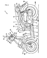
- Fig. 2 is a left profile of a scooter type motorcycle having a meter unit pertaining to the example of the invention.
- the forward, backward, left, right and other directions in the following description are the same as the respectively corresponding ones of the vehicle.
- the body frame of a motorcycle 1 has a main frame 2 and a seat rail 3.
- the main frame 2 is a U-profiled body having an upright part 21 whose forward end is joined to a head pipe 5 positioned in the forward part of the body, a horizontal part 22 extending horizontally from the upright part 21 and a slant part 23 extending back upward from the horizontal part 22.
- the forward end of the seat rail 3 is joined to the slant part 23 of this main frame 2.
- the head pipe 5 rotatably supports a steering shaft 7a to whose lower end a front fork 6 is coupled, a front wheel WF is journaled to the lower end of the front fork 6, and a handlebar 7 is fitted to the upper end of the steering shaft 7a.
- a grip 7b is fitted to each of the two ends of the handlebar 7.
- a power unit 9 in front of which an engine 8 is provided is supported to be oscillable up and down by an axle 10, and the rear part of the power unit 9 is linked to a rear cushion 11 suspended from the seat rail 3.
- the power unit 9 is provided with a transmission and a reduction gear, not shown, having known configurations for speed transmission and speed reduction, and a rear wheel WR is fitted to the output shaft (not shown) of the reduction gear.
- Tandem seats 12 integrally formed of a rider's seat and a pillion are mounted on the seat rail 3. Underneath the tandem seats 12 a fuel tank 13 is arranged, and also is arranged a store box 15 into which a helmet 14 can be stored.
- the handlebar 7 is covered by a handlebar cover 16 all around except the grip parts at the left and right ends.
- the handlebar cover 16 has a front cover and a rear cover 18 to be described in detail afterwards, a head lamp 20 is built into the front cover 17, and a meter unit (to be described afterwards) is incorporated into the rear cover 18.
- the front cover 17 of the handlebar cover 16 has a head lamp opening for fitting the head lamp 20, and in the rear cover 18 a meter unit opening for fitting the meter unit is formed.
- a pair of left and right sub-covers 19 formed separately from the front cover 17 and the rear cover 18 are disposed on the two sides (two flanks) of meter unit and the head lamp 20, a pair of left and right sub-covers 19 formed separately from the front cover 17 and the rear cover 18 are disposed.
- the front cover 17, the rear cover 18 and the sub-covers 19 are separate parts from one another.
- the sub-covers 19 are components that so extend in a range from the front cover 17 to the rear cover 18 that their front and rear ends adjoin the meter unit and the head lamp 20 arranged separately in the front and rear parts of the body.
- Mirrors 24 are arranged at the left and right ends of the front cover 17, and a wind screen 26 is arranged over a meter visor 25 that is in contact with the upper sides of the head lamp 20 and the meter unit.
- This wind screen 26 is fitted to a pair of left and right wind screen stays (to be described afterwards with reference to Figs. 6 and 7 ) disposed vertically penetrating the sub-covers 19.
- a front cover 27 and a leg shield 28 partially surrounding the head pipe 5 and the main frame 2 are provided, and a step floor 29 and an under cover 31 surrounding the rest of the main frame 2 are provided. Also, body side covers 32 and a body rear cover 33 surrounding the seat rail 3 are provided.
- a brake caliper 30 is disposed on the front fork 6.
- a front fender 34 is provided over the front wheel WF, and a rear fender 36 is provided over the rear wheel WR.
- An air cleaner 37 for cleaning the air let into the engine 8 is arranged above the power unit 9.
- Fig. 1 is a top view of the essential part of the motorcycle 1 including the handlebar cover 16; Fig. 3 , a front perspective view of the same; Fig. 4 , a rear perspective view of the same; and Fig. 5 , a left profile of the same.
- the handlebar cover 16 has the front cover 17 and the rear cover 18, and the sub-covers 19, the head lamp 20, a meter unit 38 and the meter visor 25 are fitted to the handlebar cover 16.
- the rear end of the front cover 17 and the front end of the rear cover 18 are butted against each other to constitute a border line 40 (see Fig. 1 and Fig. 5 ).
- the left and right external side surfaces of the sub-covers 19 face the front cover 17 and the rear cover 18, and their front end surfaces oppose the left and right upper end surfaces of the head lamp 20.
- their left and right internal side surfaces face side surfaces of the meter visor 25, and their rear end surfaces oppose the left and right front end surfaces of the meter unit 38.
- the sub-covers 19 are arranged adjacent to the front and rear covers 17 and 18, the head lamp 20, the meter unit 38 and the meter visor 25.
- some degree of integration is achieved among mutually separate components including the front cover 17 and the rear cover 18 constituting the handlebar cover 16 together with the head lamp 20, the meter unit 38 and the meter visor 25 by providing the sub-covers 19 which adjoin every one of them.
- the front and rear parts of the sub-covers 19 as to abut face to face on the head lamp 20 and meter unit 19, a feel of integration can be given to these components arranged apart from each other in the front-to-rear direction of the body.
- the border line 40 of the front cover 17 and the rear cover 18 form a peak (or an edge) line as the front inclined surface of the front cover 17 and the rear inclined surface of the rear cover 18 meet each other, and the sub-covers 19 also form a chevron having a peak in its profile (see Fig. 5 ).
- a dimmer switch 41 on the left side part of the rear cover 18, a dimmer switch 41, a horn switch 42, and a turn signal switch 43 are provided in the descending order. Further, on the right side part of the rear cover 18, an engine stop switch 44 and a starter switch 45 are provided in the upper and lower positions, respectively. These switches 41 through 45 are so fitted that the manipulating elements of the switches are oriented backward, namely toward the rider sitting on the seat 12 through openings formed in the rear cover 18.
- Fig. 1 shows the handlebar cover 16 before being fitted with the switches 41 through 45; out of the openings formed in the rear cover 18 to fit the switches 41 through 45, an opening 46 for the dimmer switch 41, an opening 47 for the horn switch 42 and an opening 48 for the engine stop switch 44 are seen.
- openings 49 and 49 for checking the oil in a master cylinder (not shown) that supplies brake oil to a brake are formed.
- Openings 50 for the handlebar are formed to enable the handlebar 7 to penetrate the left and right flanks of the rear cover 18 and to protrude on both the left and right sides (see Fig. 4 ).
- the grips 7b and 7b are fitted to the grip parts of the handlebar 7 (see Fig. 3 ).
- openings 52 for brake levers are formed to enable brake levers 51 to penetrate the left and right flanks of the front cover 17 as shown in Fig. 3 and Fig. 5 and to protrude on both left and right sides.
- openings 54 permitting penetration of mirror stays 53 that support the mirrors 24 are formed behind the front cover 17. These openings are U-shaped, opening toward the border line 40.
- the rear cover 18 has a V-shaped edge 55 which is narrow in the rear part (lower part in the drawings) and expanded in left-to-right width toward the forward part (upper part in the figures) as shown in Fig. 1 and Fig. 4 and, together with the edge of a bridge 72 (see Fig. 6 ) to be described afterwards, forms an opening for fitting the meter unit.
- the meter unit 38 is so arranged as to keep its rear surface (lower flank in the figures) along this V-shaped edge 55.
- the upper edge of the head lamp 20 abuts face to face on the front edges of the meter visor 25 and the sub-covers 19, and its left, right and bottom parts abut face to face on the front cover 17.
- the head lamp 20 is provided with a reflector 56, and a bulb 57 is arranged in the focal position of the reflector 56.
- the front surface of the head lamp 20 is covered with a lens 58.
- the lens 58 as can be understood from Fig. 20 , has a lens surface the upper end of which is positioned behind the lower end.
- bosses for use in putting the covers together and bosses for use in coupling each of the covers to the head lamp 20 and the meter unit 38 are formed.
- the part of the handlebar cover 16 toward the lower end is formed in a cylindrical body to surround the steering shaft 7a.
- bosses 59 protruding toward the front cover 17 are formed toward the lower end of the rear cover 18 constituting the rear half of the cylindrical body of the handlebar cover 16.
- dents 60 having holes permitting penetration of set-screws toward the rear cover 18 are formed in the front cover 17 in the positions respectively opposite the bosses 59 in the rear cover 18.
- Bosses 63 protruding toward the rear cover 18 are formed on the parts of the front cover 17 to the left and right of the head lamp 20. Set-screws (not shown) that allow brackets (not shown) protruding to the left and right from the head lamp 20 to be inserted from the rear cover 18 are screwed into these bosses 63. Also on the front cover 17, bosses 17a protruding toward the rear cover 18 are formed, and the tips of bosses 18a (to be described afterwards) protruding from the rear cover 18 toward the front cover 17 are opposed to these bosses 17a. Further in the front cover 17, a boss 67 into which a set-screw (to be described afterwards with reference to Fig. 20 ) that can pass through a hole in a bracket 79 formed above the head lamp 20 is to be screwed is formed.
- bosses 61 protruding toward the meter unit 38 are formed in positions matching the rear side walls of the meter unit 38.
- set-screws that can be inserted into holes in stays 38A (to be described afterwards with reference to Fig. 11 ) formed in the meter unit 38 from the meter unit 38 side are screwed.
- bosses 62 protruding toward the front cover 17 are formed adjoining oil level check openings 49. These bosses 62 are provided to join the rear cover 18 to the handlebar 7 (the manner of joining to be described afterwards with reference to Fig. 7 ).
- the meter visor 25 is fitted to the rear cover 18 with two set-screws 66. As shown in Fig. 3 , the rear cover 18 is provided with a pair of left and right stays 77 having threaded holes into which the set-screws 66 are screwed (see Fig. 3 and Fig. 6 ).
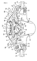
- Fig. 6 is a rear perspective view of the handlebar cover 16 in a state in which the meter visor 25 and the front cover 17 are taken off
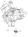
- Fig. 7 a perspective view of the interior of the essential part of the rear cover 18, wherein the same reference signs as in Figs. 1 through 5 denote respectively the same elements.
- the sub-covers 19 have stays 19a bulging out to the side facing the meter visor 25 and have hanging-down pawls 19b, 19c, and 19d bulging out downward on the sides facing the front cover 17 and the rear cover 18.
- the stays 19a have holes 64, set-screws 65 are passed through these holes 64 from underneath as shown in Fig.
- an assembly integrating the meter visor 25 and the sub-covers 19 can be engaged with a front case 17 and a rear case 18 by inserting the hanging-down pawls 19b, 19c and 19d from above into the respectively matching grooves in the front case 17 and the rear case 18.
- an indicator displaying section 68 is disposed above the meter unit 38.
- the indicator displaying section 68 is provided with turn signal indicators 69 and 70 arranged in one row in the left-right direction and the lighting state indicator 71 of the head lamp 20 arranged between the turn signal indicators 69 and 70.
- a part of the rear cover 18 has the bridge 72 extending from the left and right parts of the meter unit 38 toward the central part and crosses the area ahead of the indicator displaying section 68, and this bridge 72 is formed by the forward protrusion of a boss 74 to be used for joining the bridge 72 to the stay 73 (to be described afterwards with reference to Fig. 12 ) of the lower case 106 of the meter unit 38.
- the bridge 72 is provided with a hole 76 to let a set-screw 75 that penetrates the boss 74 and is screwed into the stay 73 and the bosses 18a disposed in two positions and having holes to allow set-screws (see Fig. 10 ) to penetrate to join the meter visor 25 to the bridge 72.
- the stays 77 and 77 are erected. These stays 77 have screw holes for fitting the meter visor 25 to the rear cover 18 with the set-screws 66 and 66 (see Fig. 4 ).
- a head lamp housing 78 constituting part of the head lamp 20
- the bracket 79 for fitting the housing 78 to the meter visor 25 protruded.
- a wind screen stay 80 to support the wind screen 26 is provided penetrating it.
- the wind screen stays 80 has studs 81 in four positions forward for fitting the wind screen 26.
- a bracket 82 is joined forward to the handlebar 7, and to the bracket 82, extending farther upward, another bracket 83 is joined.
- brackets 84 are joined and, by bolting these brackets 84 to the bracket 82 on the handlebar side, the wind screen 26 is joined to the handlebar 7.
- Reference sign 85 denotes a bolt inserted from the bracket 84 side, and reference sign 86, a nut joined to the bottom face of the bracket 82,
- the bracket 83 opposes the front end face of the bosses 62 formed in the rear cover 18 and, by screwing a set-screw 87 into the bosses 62 through the bracket 83, the rear cover 18 is joined to the handlebar 7.
- Reference sign 88 denotes a fitting hole for the turn signal switch 43.
- reference sign 89 denotes a linking member for linking the handlebar 7 to the steering shaft 7a.
- Fig. 8 is a cross-sectional view of the bosses 63 of the front cover 17. Holes 63a to let set-screws (tapping screws) be screwed into are formed in the bosses 63.
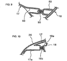
- Fig. 9 is a cross-sectional view of the dents 60 formed in the front cover 17, wherein the bosses 59 of the rear cover 18 are also shown.
- the bottoms of the dents 60 of the front cover 17 holes permitting penetration of set-screws 90 are formed, while threaded holes to allow these set-screws 90 to be screwed in are formed in the bosses 59 formed in the rear cover 18. Therefore, the front cover 17 and the rear cover 18 can be joined together by inserting the set-screws 90 from the front cover 17 side and screwing them into the rear cover 18.
- Fig. 10 is a cross-sectional view of the area in which the bosses 17a of the front cover 17 and the bosses 18a of the rear cover oppose each other.
- the bosses 17a protrude toward the rear cover 18.
- the tips of these bosses 17a oppose the tips of the bosses 18a formed on the rear cover 18 side.
- Holes permitting penetration of set-screws 18c are in the bosses 18a on the rear cover 18 side, and threaded holes to allow the set-screws 18c to be screwed in are formed in the bosses 17a on the front cover 17 side.
- This configuration enables the set-screws 18c to be screwed into the threaded holes of the bosses 17a from the rear cover 18 side through the bosses 18a and thereby to join the front cover 17 and the rear cover 18.
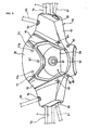
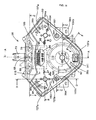
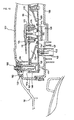
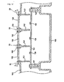
- Fig. 11 is a front view of the meter unit 38; Fig. 12 , a bottom view of the meter unit 38; Fig. 13 , a cross-sectional view between arrows A and A in Fig. 11 ; Fig. 14 , a cross-sectional view between arrows B and B in Fig. 11 ; Fig. 15 , a cross-sectional view between arrows C and C in Fig. 11 ; Fig. 16 , a cross-sectional view between arrows D and D in Fig. 11 ; and Fig. 17 , a cross-sectional view between arrows E and E in Fig. 11 .
- the meter unit 38 whose outer shape is formed substantially in an inverted triangle as viewed from front has an instrument section 91 and the indicator displaying section 68 positioned ahead of the instrument section 91.
- the instrument section 91 includes a speedometer 92 as a first instrument, a fuel gauge 93 as a second instrument, a cooling water thermometer 94 as a third instrument, a mileage meter 95 and a clock 96 (the mileage meter 95 and the clock 96 are digital indicators).
- the speedometer 92 is arranged backward at the center of the meter unit 38 (toward the bottom in Fig. 11 ), the fuel gauge 93, in the right side part of the meter unit 38 toward the front (toward the top right in Fig.
- the cooling water thermometer 94 in the left side part of the meter unit 38 toward the front (toward the top left in Fig. 11 ) and the mileage meter 95 and the clock 96, substantially in the middle between the fuel gauge 93 and the cooling water thermometer 94.
- the meter unit 38 has an overall shape of inverted triangle which is narrower left to right in the rear area where the speedometer 92 is arranged and broader in the front area where multiple instruments are arranged in the left-right direction; in particular, the instrument section 91 is a deformed inverted triangle having display regions 38a and 38b bulging out forward left and right (upward left and right in Fig. 11 ) to enable the pointers of the fuel gauge 93 and the cooling water thermometer 94 to turn. And between the display regions 38a and 38b, namely between the bulging-out parts, the indicator displaying section 68 is disposed.
- an oil abnormality indicator 97 In the instrument section 91, an oil abnormality indicator 97, an ABS indicator 98 and an immobilizer indicator 99 are provided in addition to the instruments. Further, on the left side of the upper surface of the meter unit 38, a manipulating element 100 to have the mileage meter 95 accomplish trip displaying is provided, and on the right side a manipulating element 101 for clock setting is provided.
- the cases of the meter unit 38 include an upper case 102 and a lower case (to be described afterwards), and the manipulating elements 100 and 101 are, out of the upper case 102, rubber-made components to be disposed in parts 103 and 104 bulging out from the left and right edges toward the speedometer 92.
- the upper case 102 has a bulging-out part 105 to form the indicator displaying section 68.
- the bulging-out parts 103, 104 and 105 have horizontal parts (the parts 103 and 104 shown in Fig. 11 ) bulging inward from flanks of the upper case 102 of the meter unit 38 and reverse parts 134 hanging down, namely over a dial plate 110, from these horizontal parts 103 and 104.
- the horizontal parts namely the bulging-out parts 103, 104 and 105, including the reverse parts 134, are formed of opaque members unlike a transparent lens 107 covering the instrument section 91 of the meter unit 38.
- the bulging-out part 103 made of an opaque member is disposed between the speedometer 92 and the cooling water thermometer 94, while the bulging-out part 104 on the other hand is disposed between the speedometer 92 and the fuel gauge 93.
- the whole upper case may be an opaque member or only the bulging-out parts 103, 104 and 105 including the reverse parts may be opaque.
- the pair of stays 38A are provided on the flanks of the lower case 106 of the meter unit 38. These stays 38A, opposing the bosses 62 (see Fig. 4 ) of the rear cover 18, are used when the meter unit 38 is fixed to the rear cover 18 by screwing set-screws (not shown), which can be passed from the stay 38A side, into the bosses 62.
- the upper part in Fig. 11 (namely the part toward the front part of the body) adjoins the bulging-out part 105, and to the left, right and underneath there are level-gapped surfaces 107a a step lower than the upper surface of the lens 107, and the configuration is such that the edges of the handlebar cover 16 (the sub-covers 19 and the rear cover 18) superpose these level-gapped surfaces 107a.
- the rear cover 18 has surfaces 18h (surface adjoining the V-shaped edge 55) continuous to the surface of the meter unit 38 and concaves 18j, a level below these surfaces 18h, in which oil level check openings 49 and 49 for the master cylinder are formed.
- the front edges 103a and 103b of the bulging-out part 103 and the rear edges 103b and 104b of the bulging-out part 104 of the meter cases are continuous to the curved parts forming the concaves 18j of the rear case 18, namely crest lines 170, 171, 172 and 173 to manifest a unique appearance giving an impression of continuity between the meter unit 38 and the rear cover 18.
- the cases of the meter unit 38 include the upper case 102, the lower case 106 and the lens 107 fitted to the upper case 102.
- the upper case 102 is a cylindrical member, namely open in the top and bottom faces, and the top face includes the bulging-out parts 103 and 104 which are among the opaque members referred to above.
- the lower case 106 is open in the top face, and the open end is joined to the bottom end of the upper case 102.
- the bottom face of the lower case 106 is not substantially open except that an opening 147 for socket is provided.
- the lens 107 and the upper case 102 are joined to each other by insert molding.
- the stay 73 protrudes upward in front of the lower case 106 (toward the upper right in Fig. 13 ), and this stay 73 is joined by using the set-screw 75 that penetrates the boss 74 formed in the bridge 72 of the rear cover 18.
- the meter unit 38 is caused to be held by the rear cover 18 (the bridge 72) by joining this stay 73 and the stays 38A to the rear cover 18 with set-screws.
- the lens 107 is snapped onto the upper case 102, and a circuit board (hereinafter referred to as simply "the board") 108, an inner case 109 and the dial plate 110 are disposed in the space between the upper case 102 and the lower case 106.
- the board a circuit board (hereinafter referred to as simply "the board") 108, an inner case 109 and the dial plate 110 are disposed in the space between the upper case 102 and the lower case 106.
- the region in which the lens 107 and the dial plate 110 including a hole or a notch 110a superpose each other in a planar view of the meter unit 38 is defined as the display face region (see Fig. 16 ).
- the lens 107 covers the upper surface of the dial plate 110 to constitute the display face region.
- the horizontal parts 103 and 104 bulge out from the upper case 102 toward the lens 107 in the display face region to allow the manipulating elements 100 and 101 to be fitted.
- the board 108 is held over ribs 111 protruding upward from the lower case 106 (see Fig. 15 and Fig. 16 ) and fitted to the lower case 106 with multiple set-screws 112.
- the set-screws 112 penetrate the board 108 and are screwed into the inner case 109. This causes the board 108 and the inner case 109 to be jointly fastened to the lower case 106.
- the dial plate 110 is fitted from above to the inner case 109 by using set-screws 113.
- LEDs (light emitting diodes) 114, 115, 116, 117, 118, 119, 120 and 121 are provided, which make clearer the readings on the dial plate 110 by irradiating the dial plate 110 with light from behind.
- the LED 114 intended to irradiate with light the outer circumference of the speedometer 92, irradiates with light a region limited by an optical waveguide 123 formed in the inner case 109.
- the LED 115 intended to irradiate with light the inner circumference of the speedometer 92 (namely the central part of the speedometer pointer 124), irradiates with light a region limited by an optical waveguide 125 surrounded by the inner case 109.
- a socket 146 provided with terminals 145 for supplying power to components on the board 108 from an external power source and outputting detection signals of a switch 132 among others is disposed on the rear surface of the board 108.
- the socket 146 penetrating the opening 147 for socket formed in the lower case 106, can be coupled with a plug not shown.
- the LED 116 intended to illuminate the outer circumference of the cooling water thermometer 94, irradiates with light a region limited by an optical waveguide 126 surrounded by the inner case 109.
- the LED 117 intended to illuminate the inner circumference of the cooling water thermometer 94 (namely the central part of the cooling water thermometer pointer 127), irradiates with light a region limited by an optical waveguide 128 surrounded by the inner case 109.
- the LED 118 intended to illuminate the oil abnormality indicator, irradiates with light from behind a transparent area for oil abnormality indication (the oil abnormality indicator shown in Fig. 11 ) 97 formed in the dial plate 110 through an optical waveguide 129 surrounded by the inner case 109.
- the LED 119 is a backlight for the mileage meter 95 and the clock 96.
- the LED 120 irradiates with light the ABS indicator 98 on the dial plate 110 from behind.
- the LED 121 irradiates with light from behind the immobilizer indicator 99 on the dial plate 110 through an optical waveguide 122 surrounded by the inner case 109.
- the speedometer 92 and the cooling water thermometer 94 have drivers 130 and 131 and pointers 124 and 127 respectively turned by the drivers 130 and 131.
- the fuel gauge 93 also has a similar driver and pointer.
- the board 108 is provided with the switch 132 which detects the operation to cause the speedometer 92 to accomplish trip displaying.
- a rod 133 as an operation transmitting member, held to be movable up and down in the inner case 109, is provided and, above this rod 133, the lower end of the manipulating element 100 is positioned.
- This configuration causes, when the manipulating element 100 is pressed from above, the manipulating element 100 to be displaced downward to press the rod 133, and this action turns on the switch 132.
- a similar switch and rod are disposed to match the manipulating element 101 for setting the clock 96.
- the bulging-out part 103 of the upper case 102 in which the manipulating element 100 is disposed has a reverse part (namely a vertical wall) 134, and the presence of this vertical wall 134 prevents complexity of the appearance by keeping the manipulating elements of the switch 132, including the lower part of the manipulating element 100, the rod 133 and parts of the rod 133 supporting the inner case 109, from being visible through the lens 107.
- a region 38c in which the speedometer 92 is disposed and the region 38a in which the cooling water thermometer 94 is disposed can be distinctly partitioned from each other by the vertical wall 134. Similar reverse parts are also provided in the bulging-out part 104 and the indicator displaying section 68 of the upper case 102 in which the manipulating element 101 is disposed, and have the same function as the vertical wall 134.
- the rod 133-supporting part of the inner case 109 has a hole vertically penetrating the dial plate 110.
- This hole may be a notch (to be described next) formed inward from the outer circumference to facilitate arrangement of the manipulating elements 100 and 101 in the region of the dial plate 110.
- Fig. 21 is a plan of the essential part of the dial plate 110 having a notch.
- the notch 110a is formed in the dial plate 110 from the outer circumference toward the inside (the side where instruments are arranged).
- a part (supporting member) of the inner case 109 supporting the rod 133 and the rod 133 to be movable up and down is positioned within the notch 110a.
- the part of the inner case 109 supporting the rod 133 and the rod 133 are so surrounded by the part 103 bulging out horizontally from the upper case 102, which is an opaque member, and the reverse part 134 extending vertically from the part 103 as not to be visible from outside through the lens 107.
- a vertical wall 135 and a vertical wall 136 farther inside are disposed, and in a region surrounded by these vertical walls 135 and 136 and an external wall 137 of the upper case 102, the indicator displaying section 68 is formed.
- a lens 138 is snapped into each of three openings 158, 159 and 160 (only 160 is shown in Fig. 13 ; see Fig. 17 and Fig. 19 for the rest), and underneath the lenses 138, an LED board 140 is disposed separately from the board 108 and in a higher position than the board 108, and an LED 139 is fitted on the board 140.
- an emblem 141 is disposed on the inner case 109 in a position backward from the speedometer 92 and the immobilizer indicator 99 (downward in Fig. 11 and to the left in Fig. 13 ).
- the emblem 141 is so fitted to the bottom of a dent 109a by adhesion or otherwise as to be accommodated in the dent 109a formed in the upper part of the inner case 109.
- the dial plate 110 In the position matching the dent 109a, the dial plate 110 is open. And in a state in which the dial plate 110 is fitted to the inner case 109, the upper end face of the dent 109a tightly adheres to the rear surface of the dial plate 110.
- the light of the LED 121 for the immobilizer indicator 99 does not leak toward the emblem 141.
- the emblem 141 can be stuck to the dent 109a through the opening in the dial plate 110 after fitting the dial plate 110 to the inner case 109 and, moreover, the alignment of the emblem 141 is facilitated by utilizing the walls of the dent 109a.
- the LED board 140 constituting the indicator displaying section 68 is fixed to the lower case 106 with set-screws 142.
- the lenses 138 and the LEDs 139 are provided for turn signaling and lighting of head lamp indication, respectively.
- the upper case 102 is provided with multiple vertical walls 143 for limiting the areas for turn signaling and lighting of head lamp indication.
- the meter visor 25 having openings 158, 159 and 160 are so fitted as to cover the indicator displaying section 68 except the parts opposing the lenses 138 above.
- the openings are so disposed matching the indicators 69 through 71, 158 and 159 as to allow the turn signal indicators 69 and 70 to be seen through and 160 to allow the lighting state indicator 71 to be seen through.
- the meeting part between the upper case 102 and the lower case 106 has, with reference to Fig. 16 for instance, a reduced width part 148 formed on the lower edge of the upper case 102, a groove 149 so formed on the upper edge of the lower case 106 as to hold the reduced width part 148 from both sides, and a seal 150 that is accommodated in the bottom of the groove 149 and, in the assembled state, pressed by the reduced width part 148 toward the bottom of the groove 149.
- Fig. 18 is a cross-sectional view between arrows F and F in Fig. 11 and shows the joining part between the upper case and the lower case.
- a boss 151 bulging out toward the outer circumference from the upper case 102 and extending toward the lower case 106 is formed, and a bracket 152 which extends down from the upper edge of the lower case 106 and whose lower end horizontally bulges outward.
- the lower end face of the boss 151 opposes the upper surface of the horizontally bulging-out part of the bracket 152.
- a screw hole 153 extending up and down is formed in the boss 151, and a hole permitting vertical penetration of a set-screw 154 is formed in the horizontally bulging-out part of the bracket 152.
- bracket 152 including the horizontally bulging-out part and the set-screw 154 are also shown in Fig. 12 .
- Fig. 19 is a perspective view of the rear left part of the meter visor 25.
- the shape of the meter visor 25 will be further described with reference to Fig. 4 and Fig. 13 together.
- the meter visor 25 has a peak 25p in the vicinity of the border line 40 between the front cover 17 and the rear cover 18, and includes a front surface 155 inclining down forward from the peak 25p, a rear surface 156 inclining down backward from the peak and a rear edge 157 bulging out from the rear surface 156 toward the meter unit 38 to constitute a cover of the indicator displaying section 68.
- the rear surface 156 is arranged substantially vertically, and the rear edge 157 is a surface arranged substantially in parallel to the dial plate 110 of the meter unit 38.
- the rear edge 157 has openings 158, 159 and 160 having shapes matching the top faces the turn signal indicators 69 and 70 and the lighting state indicator 71.
- the rear surface 156 includes left and right side parts 161 and 161 and a central part 162 sandwiched between the two side parts 161 and 161, and the central part 162 constitutes a dent a level lower than and ahead of the two side parts 161 and 161. And a region ahead of the openings 158 through 160 in the rear edge 157 extends as far as to the central part of the rear surface 156, namely the dent 162. To add, holes 163 for inserting the set-screws 66 and 66 and seats 164 are formed in the two side parts 161 and 161.
- the presence of the dent 162 a level lower than and ahead of the indicator displaying section 68 can prevent the rear surface 156 of the meter visor 25 from intercepting the field of view when one looks at the indicator displaying section 68 and thereby enhance the visibility of indicators.
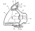
- Fig. 20 is a vertical cross-sectional view of the head lamp 20.
- the head lamp 20 has, as described above, the reflector 56, the bulb 57, the lens 58, and the head lamp housing 78 accommodating the bulb 57 and the reflector 56.
- the bracket 79 protrudes at the top of the head lamp housing 78, and the boss 67 formed in the front cover 17 opposes the front surface of the bracket 79.
- a rubber bush boss 174 is snapped into the bracket 79, and a set-screw 175 is screwed into the boss 67 through a hole formed in this rubber bush boss 174.
- Brackets similar to the bracket 79 bulge out to the left and right of the head lamp housing 78, and are joined to the bosses 63 by using set-screws.
- the rear end of the lens 58 is joined to the front end of the head lamp housing 78.
- the reflector 56 has an aiming shaft 176 extending to the left and right, and the reflector 56 and the bulb 57 supported by the reflector 56 are supported to be oscillable up and down by the aiming shaft 176 in the head lamp housing 78.
- an aiming bolt 177 is screwed in, and the tip of this aiming bolt 177 is formed in a bulb.
- a bracket 178 bulging downward from underneath the reflector 56 is formed, and the bulb at the tip of the aiming bolt 177 is joined to a bulb receptacle 179 on this bracket 178 to form a universal joint.
- the reflector 56 can be oscillated up and down centering on the aiming shaft 176 in accordance with feeding by the aiming bolt 177, and the irradiating direction of the head lamp 20 can be adjusted accordingly.
- oscillated positions of the reflector 56 are indicated in two-dot chain lines.
- a cap 180 to cover the part behind the bulb 57 is fitted in the rear part of the head lamp housing 78. Underneath the cap 180, a cylindrical cable holder 181 which permits penetration of a cable (not shown) for feeding power to the bulb 57 is formed.
- the motorcycle is not limited to a vehicle of an internal combustion engine-driven type, but the objects of application also include handlebars of a hybrid vehicle using an internal combustion engine and an electric motor or of an electromotive vehicle. Therefore, the types and numbers of switches disposed on the handlebar cover 16 or of instruments and indicators provided on the meter unit 38 can be varied to be suitable for the type of the vehicle.
- the present invention is directed to reduce the meter unit in size and to improve the manipulating ease of switches disposed in the meter unit.
- a meter unit 38 is arranged in an opening for meters disposed in a handlebar cover 16 of a motorcycle 1.
- a lens 107 joined to the upper part of an upper case 102 of meter cases covers the top face of a dial plate 110.
- the upper case 102 includes opaque parts 103 and 104 bulging out toward the lens 107, and switch manipulating elements 100 and 101 are fitted to the opaque parts 103 and 104.
- the dial plate 110 is common to multiple instruments 92, 93 and 94, and the display region of the multiple instruments is partitioned by the opaque parts.
- the switch manipulating elements 100 and 101 are intended for manipulating switches 132 on a board 108 positioned lower than the dial plate 110.
- the rear flanks of the switch manipulating elements are covered by reverse parts 134 of the opaque parts.
Description
- This invention relates to a motorcycle comprising a meter unit, and more particularly to a motorcycle comprising a meter unit that is capable of giving a novel external shape.
- Among conventional saddle-mounting vehicles including motorcycles, what is provided with a sub-cover covering the part between the external circumference of the meter unit and the periphery of the opening of the handlebar cover on which the meter unit is to be fitted is described in
Japanese patent document No. JP-A-2006-96106 - A motorcycle comprising a meter unit according to the preamble of
claim 1 is known fromEP 1 643 262 A1EP 1 447 282 A2EP 1 970 243 A1 - Generally, items provided with a digital display on the display face of the meter unit may have various operational switches including a resetting switch for the trip meter unit and a clock setting switch in addition to a speedometer, a fuel gauge and the like. Since these switches are provided as electrical switches on the meter board, it is easier for electrical meter arrangement to dispose the switches within the display face of the meter unit, but disposing such switches within the display face of the meter unit may cause the dial plate constituting the display face and the switches visually to melt together and to become less readable by the rider. However, any known sub-cover such as the one described in
Japanese patent document No. JP-A-2006-96106 - An object of this invention is to provide a motorcycle comprising a meter unit that is capable of giving a novel external shape of the meter unit and enabling the operating ease of switches on the display face to be enhanced.
- This object is achieved by a motorcycle according to
claim 1. In accordance with the present invention there is provided a motorcycle as set out inclaim 1. Preferred embodiments of the present invention are laid down in the appended dependent claims 2-6. - The invention has its first characteristic in that a motorcycle comprising a meter unit comprises meter cases; a dial plate of instruments disposed in the meter cases; digital displays disposed on the dial plate; and a lens fitted to the meter cases and covering an upper surface of the dial plate to constitute a display face region, wherein the meter cases are arranged in an opening for meters provided in a handlebar cover covering a handlebar for steering the vehicle, the meter cases include opaque parts that extend toward the lens and extends into the display face region, and switch manipulating elements for varying the mode of displaying on the digital displays are fitted to the opaque parts.
- Furthermore, the switch manipulating elements are intended for use in manipulating switches which are provided on a circuit board arranged underneath the dial plate and the meter unit further comprises rods positioned below lower ends of the switch manipulating elements and above detection sections of the switches to intervene between the switch manipulating elements and the switches, and the opaque parts include reverse parts which are turned over toward the dial plate and cover flanks of the rod.
- The invention also has its second characteristic in that the meter cases include a cylindrical upper case including the opaque parts and a lower case which is joined to a bottom end of the upper case and whose upper surface is open, and the lens is jointed to an upper end of the upper case.
- The invention also has its third characteristic in that the dial plate is common to multiple instruments and display regions of the multiple instruments are partitioned by the opaque parts.
- The invention also has its fourth characteristic in that a notch is disposed in a part of the dial plate, and the rod and a supporting member thereof extend vertically through the notch.
- The invention also has its fifth characteristic in that the multiple instruments include a first instrument and second and third instruments arranged apart from each other left and right ahead of the first instrument, and one of the opaque parts is disposed between the first instrument and the second instrument, and another of the opaque parts is disposed between the first instrument and the third instrument.
- Further, the invention has its sixth characteristic in that the handlebar cover has an oil level check opening for a brake master cylinder; the oil level check opening is disposed at the bottom of a dent formed in the handlebar cover; and external shapes of the opaque parts are continuous to surrounding crest lines constituting the dent.
- According to the invention having the first characteristic, as the meter cases have opaque parts bulging out toward the lens fitted over the meter cases and the switch manipulating elements are disposed in these opaque parts, the upper surface of the meter unit, namely the display face, can be given a novel external shape by merely varying the shape of the opaque parts without having to vary the external shape of the meter unit. Furthermore, even if the switch manipulating elements are disposed within the display face region, the dial plate and the switch manipulating elements can be readily distinguished from each other by the opaque parts, making it possible to enhance the ease of use. Also, as the manipulating elements can be arranged by positively utilizing the space within the display face region, the size of the meter unit can be reduced.
- Furthermore, since the rod as an operation transmitting member between the switch manipulating elements and switches are hidden by the reverse parts of the opaque parts, the external appearance of the dial plate vicinities as seen through the lens is improved.
- Furthermore, according to the invention having the second characteristic, it can be made unnecessary to directly fit the switch manipulating elements to the lens which is a fragile member and furthermore the lens is fitted to the upper case by joining, there is no need to fasten together the lens and the lower case, resulting in enhanced durability or the lens.
- Furthermore, according to the invention having the third characteristic, when multiple items of information including the vehicle speed, cooling water temperature and remaining oil amount are to be indicated on the meter unit, as the display region can be partitioned by the opaque parts, the visibility of each individual instrument can be enhanced where a common dial plate is used.
- Furthermore, according to the invention having the fourth characteristic, where the switch manipulating elements are to be arranged in a region inward from the outer circumference of the dial plate, as the substructures of the switch manipulating elements (namely the rod and the supporting member of the rod) can be arranged in the notch in the dial plate, assembling ease is enhanced.
- Also, according to the invention having the fifth characteristic, where multiple switch manipulating elements are provided by arranging opaque parts separated to the left and right over the upper surface of the meter unit, the individual switch manipulating elements can be readily distinguished from one another.
- Also, according to the invention having the sixth characteristic, by giving continuity to the external shape of the opaque parts from the crest lines of bent parts of the handlebar cover, a novel appearance giving a sense of integration between the opaque parts and the handlebar cover can be provided. This enables an impression as if the switch manipulating elements were arranged over a separate component from the meter unit to be given.
-
-
Fig. 1 is a top view of the essential part of the motorcycle including the meter unit pertaining to one example of embodiment of the invention. -
Fig. 2 is a left profile of the essential part of the motorcycle including the meter unit pertaining to the example of embodiment of the invention. -
Fig. 3 is a front perspective view of the essential part of the motorcycle including the meter unit pertaining to one example of embodiment of the invention. -
Fig. 4 is a rear perspective view of the essential part of the motorcycle including the meter unit pertaining to one example of embodiment of the invention. -
Fig. 5 is a left profile of the essential part of the motorcycle including the meter unit pertaining to one example of embodiment of the invention. -
Fig. 6 is a rear perspective view of the essential part of the motorcycle excluding a meter visor. -
Fig. 7 is a left front perspective view of the essential part of the motorcycle excluding a front cover. -
Fig. 8 is a cross-sectional view of a boss for screwing formed in the front cover. -
Fig. 9 is a cross-sectional view of an example of joint part between the front cover and a rear cover. -
Fig. 10 is a cross-sectional view of the area in which the bosses of the front cover and the bosses of the rear cover oppose each other. -
Fig. 11 is a front view of the meter unit. -
Fig. 12 is a bottom a bottom view of the meter unit. -
Fig. 13 is a cross-sectional view between arrows A and A inFig. 11 . -
Fig. 14 is a cross-sectional view between arrows B and B inFig. 11 . -
Fig. 15 is a cross-sectional view between arrows C and C inFig. 11 . -
Fig. 16 is a cross-sectional view between arrows D and D inFig. 11 . -
Fig. 17 is a cross-sectional view between arrows E and E inFig. 11 . -
Fig. 18 is a cross-sectional view between arrows F and F inFig. 11 . -
Fig. 19 is a perspective view of the rear left part of the meter visor. -
Fig. 20 is a cross-sectional profile of the head lamp. -
Fig. 21 is a plan of the essential part of the dial plate. - One example of embodiment of the invention will be described below with reference to drawings.
Fig. 2 is a left profile of a scooter type motorcycle having a meter unit pertaining to the example of the invention. Incidentally, unless otherwise stated, the forward, backward, left, right and other directions in the following description are the same as the respectively corresponding ones of the vehicle. - In
Fig. 2 , the body frame of amotorcycle 1 has a main frame 2 and aseat rail 3. The main frame 2 is a U-profiled body having anupright part 21 whose forward end is joined to ahead pipe 5 positioned in the forward part of the body, ahorizontal part 22 extending horizontally from theupright part 21 and aslant part 23 extending back upward from thehorizontal part 22. The forward end of theseat rail 3 is joined to theslant part 23 of this main frame 2. - The
head pipe 5 rotatably supports asteering shaft 7a to whose lower end afront fork 6 is coupled, a front wheel WF is journaled to the lower end of thefront fork 6, and ahandlebar 7 is fitted to the upper end of thesteering shaft 7a. Agrip 7b is fitted to each of the two ends of thehandlebar 7. Behind the main frame 2, apower unit 9 in front of which anengine 8 is provided is supported to be oscillable up and down by anaxle 10, and the rear part of thepower unit 9 is linked to arear cushion 11 suspended from theseat rail 3. - The
power unit 9 is provided with a transmission and a reduction gear, not shown, having known configurations for speed transmission and speed reduction, and a rear wheel WR is fitted to the output shaft (not shown) of the reduction gear. Tandem seats 12 integrally formed of a rider's seat and a pillion are mounted on theseat rail 3. Underneath the tandem seats 12 afuel tank 13 is arranged, and also is arranged astore box 15 into which ahelmet 14 can be stored. - The
handlebar 7 is covered by ahandlebar cover 16 all around except the grip parts at the left and right ends. Thehandlebar cover 16 has a front cover and arear cover 18 to be described in detail afterwards, ahead lamp 20 is built into thefront cover 17, and a meter unit (to be described afterwards) is incorporated into therear cover 18. Thefront cover 17 of thehandlebar cover 16 has a head lamp opening for fitting thehead lamp 20, and in therear cover 18 a meter unit opening for fitting the meter unit is formed. - On the two sides (two flanks) of meter unit and the
head lamp 20, a pair of left andright sub-covers 19 formed separately from thefront cover 17 and therear cover 18 are disposed. Namely, thefront cover 17, therear cover 18 and the sub-covers 19 are separate parts from one another. The sub-covers 19 are components that so extend in a range from thefront cover 17 to therear cover 18 that their front and rear ends adjoin the meter unit and thehead lamp 20 arranged separately in the front and rear parts of the body. -
Mirrors 24 are arranged at the left and right ends of thefront cover 17, and awind screen 26 is arranged over ameter visor 25 that is in contact with the upper sides of thehead lamp 20 and the meter unit. Thiswind screen 26 is fitted to a pair of left and right wind screen stays (to be described afterwards with reference toFigs. 6 and7 ) disposed vertically penetrating the sub-covers 19. - A
front cover 27 and aleg shield 28 partially surrounding thehead pipe 5 and the main frame 2 are provided, and astep floor 29 and an undercover 31 surrounding the rest of the main frame 2 are provided. Also, body side covers 32 and a bodyrear cover 33 surrounding theseat rail 3 are provided. - A
brake caliper 30 is disposed on thefront fork 6. Afront fender 34 is provided over the front wheel WF, and arear fender 36 is provided over the rear wheel WR. Anair cleaner 37 for cleaning the air let into theengine 8 is arranged above thepower unit 9. - Next, the essential part of the motorcycle, namely the handlebar and the elements around it will be described in detail with reference to drawings.
Fig. 1 is a top view of the essential part of themotorcycle 1 including thehandlebar cover 16;Fig. 3 , a front perspective view of the same;Fig. 4 , a rear perspective view of the same; andFig. 5 , a left profile of the same. In these drawings, the same reference signs denote respectively the same parts. Thehandlebar cover 16 has thefront cover 17 and therear cover 18, and the sub-covers 19, thehead lamp 20, ameter unit 38 and themeter visor 25 are fitted to thehandlebar cover 16. The rear end of thefront cover 17 and the front end of therear cover 18 are butted against each other to constitute a border line 40 (seeFig. 1 andFig. 5 ). - Further, as shown in
Fig. 1 , the left and right external side surfaces of the sub-covers 19 face thefront cover 17 and therear cover 18, and their front end surfaces oppose the left and right upper end surfaces of thehead lamp 20. On the other hand, their left and right internal side surfaces face side surfaces of themeter visor 25, and their rear end surfaces oppose the left and right front end surfaces of themeter unit 38. In other words, the sub-covers 19 are arranged adjacent to the front and rear covers 17 and 18, thehead lamp 20, themeter unit 38 and themeter visor 25. - Thus, some degree of integration is achieved among mutually separate components including the
front cover 17 and therear cover 18 constituting thehandlebar cover 16 together with thehead lamp 20, themeter unit 38 and themeter visor 25 by providing the sub-covers 19 which adjoin every one of them. In particular, by so positioning the front and rear parts of the sub-covers 19 as to abut face to face on thehead lamp 20 andmeter unit 19, a feel of integration can be given to these components arranged apart from each other in the front-to-rear direction of the body. - The
border line 40 of thefront cover 17 and therear cover 18 form a peak (or an edge) line as the front inclined surface of thefront cover 17 and the rear inclined surface of therear cover 18 meet each other, and the sub-covers 19 also form a chevron having a peak in its profile (seeFig. 5 ). - In
Fig. 4 , on the left side part of therear cover 18, adimmer switch 41, ahorn switch 42, and aturn signal switch 43 are provided in the descending order. Further, on the right side part of therear cover 18, anengine stop switch 44 and astarter switch 45 are provided in the upper and lower positions, respectively. Theseswitches 41 through 45 are so fitted that the manipulating elements of the switches are oriented backward, namely toward the rider sitting on theseat 12 through openings formed in therear cover 18. -
Fig. 1 shows thehandlebar cover 16 before being fitted with theswitches 41 through 45; out of the openings formed in therear cover 18 to fit theswitches 41 through 45, anopening 46 for thedimmer switch 41, anopening 47 for thehorn switch 42 and anopening 48 for theengine stop switch 44 are seen. In therear cover 18,openings -
Openings 50 for the handlebar are formed to enable thehandlebar 7 to penetrate the left and right flanks of therear cover 18 and to protrude on both the left and right sides (seeFig. 4 ). Thegrips Fig. 3 ). - Also,
openings 52 for brake levers are formed to enablebrake levers 51 to penetrate the left and right flanks of thefront cover 17 as shown inFig. 3 andFig. 5 and to protrude on both left and right sides. Further,openings 54 permitting penetration of mirror stays 53 that support themirrors 24 are formed behind thefront cover 17. These openings are U-shaped, opening toward theborder line 40. - The
rear cover 18 has a V-shapededge 55 which is narrow in the rear part (lower part in the drawings) and expanded in left-to-right width toward the forward part (upper part in the figures) as shown inFig. 1 andFig. 4 and, together with the edge of a bridge 72 (seeFig. 6 ) to be described afterwards, forms an opening for fitting the meter unit. And themeter unit 38 is so arranged as to keep its rear surface (lower flank in the figures) along this V-shapededge 55. - In
Fig. 3 , the upper edge of thehead lamp 20 abuts face to face on the front edges of themeter visor 25 and the sub-covers 19, and its left, right and bottom parts abut face to face on thefront cover 17. Thehead lamp 20 is provided with areflector 56, and abulb 57 is arranged in the focal position of thereflector 56. The front surface of thehead lamp 20 is covered with alens 58. Thelens 58, as can be understood fromFig. 20 , has a lens surface the upper end of which is positioned behind the lower end. In thefront cover 17 and therear cover 18, bosses for use in putting the covers together and bosses for use in coupling each of the covers to thehead lamp 20 and themeter unit 38 are formed. - The part of the
handlebar cover 16 toward the lower end is formed in a cylindrical body to surround thesteering shaft 7a. InFig. 4 ,bosses 59 protruding toward thefront cover 17 are formed toward the lower end of therear cover 18 constituting the rear half of the cylindrical body of thehandlebar cover 16. And as shown inFig. 3 , dents 60 having holes permitting penetration of set-screws toward therear cover 18 are formed in thefront cover 17 in the positions respectively opposite thebosses 59 in therear cover 18. -
Bosses 63 protruding toward therear cover 18 are formed on the parts of thefront cover 17 to the left and right of thehead lamp 20. Set-screws (not shown) that allow brackets (not shown) protruding to the left and right from thehead lamp 20 to be inserted from therear cover 18 are screwed into thesebosses 63. Also on thefront cover 17,bosses 17a protruding toward therear cover 18 are formed, and the tips ofbosses 18a (to be described afterwards) protruding from therear cover 18 toward thefront cover 17 are opposed to thesebosses 17a. Further in thefront cover 17, aboss 67 into which a set-screw (to be described afterwards with reference toFig. 20 ) that can pass through a hole in abracket 79 formed above thehead lamp 20 is to be screwed is formed. - In
Fig. 4 , in therear cover 18,bosses 61 protruding toward themeter unit 38 are formed in positions matching the rear side walls of themeter unit 38. Into thesebosses 61, set-screws that can be inserted into holes instays 38A (to be described afterwards with reference toFig. 11 ) formed in themeter unit 38 from themeter unit 38 side are screwed. Further in therear cover 18,bosses 62 protruding toward thefront cover 17 are formed adjoining oillevel check openings 49. Thesebosses 62 are provided to join therear cover 18 to the handlebar 7 (the manner of joining to be described afterwards with reference toFig. 7 ). - The
meter visor 25 is fitted to therear cover 18 with two set-screws 66. As shown inFig. 3 , therear cover 18 is provided with a pair of left and right stays 77 having threaded holes into which the set-screws 66 are screwed (seeFig. 3 andFig. 6 ). -
Fig. 6 is a rear perspective view of thehandlebar cover 16 in a state in which themeter visor 25 and thefront cover 17 are taken off, andFig. 7 , a perspective view of the interior of the essential part of therear cover 18, wherein the same reference signs as inFigs. 1 through 5 denote respectively the same elements. InFig. 1 ,Fig. 5 , andFig. 6 , the sub-covers 19 havestays 19a bulging out to the side facing themeter visor 25 and have hanging-downpawls front cover 17 and therear cover 18. Thestays 19a haveholes 64, set-screws 65 are passed through theseholes 64 from underneath as shown inFig. 5 , and these set-screws 65 are screwed intobosses 25a provided in themeter visor 25 to join the sub-covers 19 to themeter visor 25. On the edges of thefront cover 17 that face the left and right external sides of the sub-covers 19, two grooves not shown are formed in positions where the hanging-down pawls rear cover 18 one groove not shown is formed in a position where the hanging-down pawls 19d can be inserted from above. Therefore, an assembly integrating themeter visor 25 and the sub-covers 19 can be engaged with afront case 17 and arear case 18 by inserting the hanging-downpawls front case 17 and therear case 18. - In
Fig. 6 , anindicator displaying section 68 is disposed above themeter unit 38. Theindicator displaying section 68 is provided withturn signal indicators lighting state indicator 71 of thehead lamp 20 arranged between theturn signal indicators - A part of the
rear cover 18 has thebridge 72 extending from the left and right parts of themeter unit 38 toward the central part and crosses the area ahead of theindicator displaying section 68, and thisbridge 72 is formed by the forward protrusion of aboss 74 to be used for joining thebridge 72 to the stay 73 (to be described afterwards with reference toFig. 12 ) of thelower case 106 of themeter unit 38. Thebridge 72 is provided with ahole 76 to let a set-screw 75 that penetrates theboss 74 and is screwed into thestay 73 and thebosses 18a disposed in two positions and having holes to allow set-screws (seeFig. 10 ) to penetrate to join themeter visor 25 to thebridge 72. - Farther outside the
bosses stays meter visor 25 to therear cover 18 with the set-screws 66 and 66 (seeFig. 4 ). - From a
head lamp housing 78 constituting part of thehead lamp 20, thebracket 79 for fitting thehousing 78 to themeter visor 25 protruded. Also, in each of the sub-covers 19, a wind screen stay 80 to support thewind screen 26 is provided penetrating it. The wind screen stays 80 hasstuds 81 in four positions forward for fitting thewind screen 26. - In
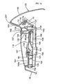
Fig. 7 , abracket 82 is joined forward to thehandlebar 7, and to thebracket 82, extending farther upward, another bracket 83 is joined. At the bottom end of the wind screen stays 80 penetrating the sub-covers 19,brackets 84 are joined and, by bolting thesebrackets 84 to thebracket 82 on the handlebar side, thewind screen 26 is joined to thehandlebar 7.Reference sign 85 denotes a bolt inserted from thebracket 84 side, andreference sign 86, a nut joined to the bottom face of thebracket 82, - The bracket 83 opposes the front end face of the
bosses 62 formed in therear cover 18 and, by screwing a set-screw 87 into thebosses 62 through the bracket 83, therear cover 18 is joined to thehandlebar 7.Reference sign 88 denotes a fitting hole for theturn signal switch 43. Further,reference sign 89 denotes a linking member for linking thehandlebar 7 to thesteering shaft 7a. -
Fig. 8 is a cross-sectional view of thebosses 63 of thefront cover 17.Holes 63a to let set-screws (tapping screws) be screwed into are formed in thebosses 63. -
Fig. 9 is a cross-sectional view of thedents 60 formed in thefront cover 17, wherein thebosses 59 of therear cover 18 are also shown. In the bottoms of thedents 60 of thefront cover 17, holes permitting penetration of set-screws 90 are formed, while threaded holes to allow these set-screws 90 to be screwed in are formed in thebosses 59 formed in therear cover 18. Therefore, thefront cover 17 and therear cover 18 can be joined together by inserting the set-screws 90 from thefront cover 17 side and screwing them into therear cover 18. -
Fig. 10 is a cross-sectional view of the area in which thebosses 17a of thefront cover 17 and thebosses 18a of the rear cover oppose each other. InFig. 10 , in the part of thefront cover 17 covered by themeter visor 25, thebosses 17a protrude toward therear cover 18. The tips of thesebosses 17a oppose the tips of thebosses 18a formed on therear cover 18 side. Holes permitting penetration of set-screws 18c are in thebosses 18a on therear cover 18 side, and threaded holes to allow the set-screws 18c to be screwed in are formed in thebosses 17a on thefront cover 17 side. This configuration enables the set-screws 18c to be screwed into the threaded holes of thebosses 17a from therear cover 18 side through thebosses 18a and thereby to join thefront cover 17 and therear cover 18. - Next, the
meter unit 38 and themeter visor 25 will be described in detail.Fig. 11 is a front view of themeter unit 38;Fig. 12 , a bottom view of themeter unit 38;Fig. 13 , a cross-sectional view between arrows A and A inFig. 11 ;Fig. 14 , a cross-sectional view between arrows B and B inFig. 11 ;Fig. 15 , a cross-sectional view between arrows C and C inFig. 11 ;Fig. 16 , a cross-sectional view between arrows D and D inFig. 11 ; andFig. 17 , a cross-sectional view between arrows E and E inFig. 11 . - In
Fig. 11 , themeter unit 38 whose outer shape is formed substantially in an inverted triangle as viewed from front has aninstrument section 91 and theindicator displaying section 68 positioned ahead of theinstrument section 91. Theinstrument section 91 includes aspeedometer 92 as a first instrument, afuel gauge 93 as a second instrument, a coolingwater thermometer 94 as a third instrument, amileage meter 95 and a clock 96 (themileage meter 95 and theclock 96 are digital indicators). Thespeedometer 92 is arranged backward at the center of the meter unit 38 (toward the bottom inFig. 11 ), thefuel gauge 93, in the right side part of themeter unit 38 toward the front (toward the top right inFig. 11 ), the coolingwater thermometer 94, in the left side part of themeter unit 38 toward the front (toward the top left inFig. 11 ) and themileage meter 95 and theclock 96, substantially in the middle between thefuel gauge 93 and the coolingwater thermometer 94. - Therefore, the
meter unit 38 has an overall shape of inverted triangle which is narrower left to right in the rear area where thespeedometer 92 is arranged and broader in the front area where multiple instruments are arranged in the left-right direction; in particular, theinstrument section 91 is a deformed inverted triangle havingdisplay regions Fig. 11 ) to enable the pointers of thefuel gauge 93 and the coolingwater thermometer 94 to turn. And between thedisplay regions indicator displaying section 68 is disposed. - In the
instrument section 91, anoil abnormality indicator 97, anABS indicator 98 and animmobilizer indicator 99 are provided in addition to the instruments. Further, on the left side of the upper surface of themeter unit 38, a manipulatingelement 100 to have themileage meter 95 accomplish trip displaying is provided, and on the right side a manipulatingelement 101 for clock setting is provided. - The cases of the
meter unit 38 include anupper case 102 and a lower case (to be described afterwards), and the manipulatingelements upper case 102, rubber-made components to be disposed inparts speedometer 92. Further, theupper case 102 has a bulging-outpart 105 to form theindicator displaying section 68. The bulging-outparts parts Fig. 11 ) bulging inward from flanks of theupper case 102 of themeter unit 38 and reverseparts 134 hanging down, namely over adial plate 110, from thesehorizontal parts parts reverse parts 134, are formed of opaque members unlike atransparent lens 107 covering theinstrument section 91 of themeter unit 38. The bulging-outpart 103 made of an opaque member is disposed between thespeedometer 92 and the coolingwater thermometer 94, while the bulging-outpart 104 on the other hand is disposed between thespeedometer 92 and thefuel gauge 93. Incidentally, the whole upper case may be an opaque member or only the bulging-outparts - On the flanks of the
lower case 106 of themeter unit 38, the pair ofstays 38A are provided. These stays 38A, opposing the bosses 62 (seeFig. 4 ) of therear cover 18, are used when themeter unit 38 is fixed to therear cover 18 by screwing set-screws (not shown), which can be passed from thestay 38A side, into thebosses 62. - Around the
lens 107 of themeter unit 38, the upper part inFig. 11 (namely the part toward the front part of the body) adjoins the bulging-outpart 105, and to the left, right and underneath there are level-gapped surfaces 107a a step lower than the upper surface of thelens 107, and the configuration is such that the edges of the handlebar cover 16 (the sub-covers 19 and the rear cover 18) superpose these level-gapped surfaces 107a. - The
rear cover 18 hassurfaces 18h (surface adjoining the V-shaped edge 55) continuous to the surface of themeter unit 38 andconcaves 18j, a level below thesesurfaces 18h, in which oillevel check openings front edges part 103 and therear edges part 104 of the meter cases are continuous to the curved parts forming the concaves 18j of therear case 18, namely crestlines meter unit 38 and therear cover 18. - The configuration of the meter unit will be further described with reference to cross-sectional views. In
Figs. 13 through 16 , the cases of themeter unit 38 include theupper case 102, thelower case 106 and thelens 107 fitted to theupper case 102. Theupper case 102 is a cylindrical member, namely open in the top and bottom faces, and the top face includes the bulging-outparts lower case 106 is open in the top face, and the open end is joined to the bottom end of theupper case 102. The bottom face of thelower case 106 is not substantially open except that anopening 147 for socket is provided. - The
lens 107 and theupper case 102 are joined to each other by insert molding. Thestay 73 protrudes upward in front of the lower case 106 (toward the upper right inFig. 13 ), and thisstay 73 is joined by using the set-screw 75 that penetrates theboss 74 formed in thebridge 72 of therear cover 18. In this way, themeter unit 38 is caused to be held by the rear cover 18 (the bridge 72) by joining thisstay 73 and thestays 38A to therear cover 18 with set-screws. - The
lens 107 is snapped onto theupper case 102, and a circuit board (hereinafter referred to as simply "the board") 108, aninner case 109 and thedial plate 110 are disposed in the space between theupper case 102 and thelower case 106. - Incidentally, with respect to this embodiment, the region in which the
lens 107 and thedial plate 110 including a hole or a notch 110a superpose each other in a planar view of themeter unit 38 is defined as the display face region (seeFig. 16 ). Thus, thelens 107 covers the upper surface of thedial plate 110 to constitute the display face region. To add, in this embodiment, thehorizontal parts upper case 102 toward thelens 107 in the display face region to allow the manipulatingelements - The
board 108 is held overribs 111 protruding upward from the lower case 106 (seeFig. 15 andFig. 16 ) and fitted to thelower case 106 with multiple set-screws 112. Incidentally, the set-screws 112 penetrate theboard 108 and are screwed into theinner case 109. This causes theboard 108 and theinner case 109 to be jointly fastened to thelower case 106. Thedial plate 110 is fitted from above to theinner case 109 by using set-screws 113. - Over the
board 108, LEDs (light emitting diodes) 114, 115, 116, 117, 118, 119, 120 and 121 are provided, which make clearer the readings on thedial plate 110 by irradiating thedial plate 110 with light from behind. - In
Fig. 15 , theLED 114, intended to irradiate with light the outer circumference of thespeedometer 92, irradiates with light a region limited by anoptical waveguide 123 formed in theinner case 109. TheLED 115, intended to irradiate with light the inner circumference of the speedometer 92 (namely the central part of the speedometer pointer 124), irradiates with light a region limited by anoptical waveguide 125 surrounded by theinner case 109. - In
Fig. 15 , asocket 146 provided withterminals 145 for supplying power to components on theboard 108 from an external power source and outputting detection signals of aswitch 132 among others is disposed on the rear surface of theboard 108. Thesocket 146, penetrating theopening 147 for socket formed in thelower case 106, can be coupled with a plug not shown. - In
Figs. 14 and16 , theLED 116, intended to illuminate the outer circumference of the coolingwater thermometer 94, irradiates with light a region limited by anoptical waveguide 126 surrounded by theinner case 109. TheLED 117, intended to illuminate the inner circumference of the cooling water thermometer 94 (namely the central part of the cooling water thermometer pointer 127), irradiates with light a region limited by anoptical waveguide 128 surrounded by theinner case 109. - In
Fig. 14 , theLED 118, intended to illuminate the oil abnormality indicator, irradiates with light from behind a transparent area for oil abnormality indication (the oil abnormality indicator shown inFig. 11 ) 97 formed in thedial plate 110 through anoptical waveguide 129 surrounded by theinner case 109. TheLED 119 is a backlight for themileage meter 95 and theclock 96. Further, theLED 120 irradiates with light theABS indicator 98 on thedial plate 110 from behind. - In
Fig. 13 , theLED 121 irradiates with light from behind theimmobilizer indicator 99 on thedial plate 110 through anoptical waveguide 122 surrounded by theinner case 109. - The
speedometer 92 and the coolingwater thermometer 94 havedrivers pointers drivers fuel gauge 93 also has a similar driver and pointer. - In
Fig. 15 andFig. 16 , theboard 108 is provided with theswitch 132 which detects the operation to cause thespeedometer 92 to accomplish trip displaying. Above the detecting section of theswitch 132, arod 133 as an operation transmitting member, held to be movable up and down in theinner case 109, is provided and, above thisrod 133, the lower end of the manipulatingelement 100 is positioned. This configuration causes, when the manipulatingelement 100 is pressed from above, the manipulatingelement 100 to be displaced downward to press therod 133, and this action turns on theswitch 132. Though not shown, a similar switch and rod are disposed to match the manipulatingelement 101 for setting theclock 96. - The bulging-out
part 103 of theupper case 102 in which the manipulatingelement 100 is disposed has a reverse part (namely a vertical wall) 134, and the presence of thisvertical wall 134 prevents complexity of the appearance by keeping the manipulating elements of theswitch 132, including the lower part of the manipulatingelement 100, therod 133 and parts of therod 133 supporting theinner case 109, from being visible through thelens 107. - A
region 38c in which thespeedometer 92 is disposed and theregion 38a in which the coolingwater thermometer 94 is disposed can be distinctly partitioned from each other by thevertical wall 134. Similar reverse parts are also provided in the bulging-outpart 104 and theindicator displaying section 68 of theupper case 102 in which the manipulatingelement 101 is disposed, and have the same function as thevertical wall 134. - The rod 133-supporting part of the
inner case 109 has a hole vertically penetrating thedial plate 110. This hole may be a notch (to be described next) formed inward from the outer circumference to facilitate arrangement of the manipulatingelements dial plate 110. -
Fig. 21 is a plan of the essential part of thedial plate 110 having a notch. InFig. 21 , the notch 110a is formed in thedial plate 110 from the outer circumference toward the inside (the side where instruments are arranged). A part (supporting member) of theinner case 109 supporting therod 133 and therod 133 to be movable up and down is positioned within the notch 110a. As can be understood fromFig. 21 , the part of theinner case 109 supporting therod 133 and therod 133 are so surrounded by thepart 103 bulging out horizontally from theupper case 102, which is an opaque member, and thereverse part 134 extending vertically from thepart 103 as not to be visible from outside through thelens 107. - In the bulging-out
part 105 of theupper case 102, avertical wall 135 and avertical wall 136 farther inside are disposed, and in a region surrounded by thesevertical walls external wall 137 of theupper case 102, theindicator displaying section 68 is formed. Namely, in the horizontal part of the bulging-outpart 105, alens 138 is snapped into each of threeopenings Fig. 13 ; seeFig. 17 andFig. 19 for the rest), and underneath thelenses 138, anLED board 140 is disposed separately from theboard 108 and in a higher position than theboard 108, and anLED 139 is fitted on theboard 140. - To add, as shown in
Fig. 11 andFig. 13 , anemblem 141 is disposed on theinner case 109 in a position backward from thespeedometer 92 and the immobilizer indicator 99 (downward inFig. 11 and to the left inFig. 13 ). Theemblem 141 is so fitted to the bottom of adent 109a by adhesion or otherwise as to be accommodated in thedent 109a formed in the upper part of theinner case 109. In the position matching thedent 109a, thedial plate 110 is open. And in a state in which thedial plate 110 is fitted to theinner case 109, the upper end face of thedent 109a tightly adheres to the rear surface of thedial plate 110. Therefore, the light of theLED 121 for theimmobilizer indicator 99 does not leak toward theemblem 141. When fitting theemblem 141, theemblem 141 can be stuck to thedent 109a through the opening in thedial plate 110 after fitting thedial plate 110 to theinner case 109 and, moreover, the alignment of theemblem 141 is facilitated by utilizing the walls of thedent 109a. - In
Fig. 17 , theLED board 140 constituting theindicator displaying section 68 is fixed to thelower case 106 with set-screws 142. Thelenses 138 and theLEDs 139 are provided for turn signaling and lighting of head lamp indication, respectively. Theupper case 102 is provided with multiplevertical walls 143 for limiting the areas for turn signaling and lighting of head lamp indication. And themeter visor 25 havingopenings indicator displaying section 68 except the parts opposing thelenses 138 above. Thus the openings are so disposed matching theindicators 69 through 71, 158 and 159 as to allow theturn signal indicators lighting state indicator 71 to be seen through. - In
Fig. 13 through Fig. 17 , the meeting part between theupper case 102 and thelower case 106 has, with reference toFig. 16 for instance, a reducedwidth part 148 formed on the lower edge of theupper case 102, agroove 149 so formed on the upper edge of thelower case 106 as to hold the reducedwidth part 148 from both sides, and aseal 150 that is accommodated in the bottom of thegroove 149 and, in the assembled state, pressed by the reducedwidth part 148 toward the bottom of thegroove 149. -
Fig. 18 is a cross-sectional view between arrows F and F inFig. 11 and shows the joining part between the upper case and the lower case. InFig. 18 , aboss 151 bulging out toward the outer circumference from theupper case 102 and extending toward thelower case 106 is formed, and abracket 152 which extends down from the upper edge of thelower case 106 and whose lower end horizontally bulges outward. The lower end face of theboss 151 opposes the upper surface of the horizontally bulging-out part of thebracket 152. Ascrew hole 153 extending up and down is formed in theboss 151, and a hole permitting vertical penetration of a set-screw 154 is formed in the horizontally bulging-out part of thebracket 152. This configuration enables, when the set-screw 154 passed from bottom to top in the horizontally bulging-out part of thebracket 152 is screwed into thescrew hole 153 of theboss 151, theupper case 102 and thelower case 106 to be assembled with each other in a sealed state via theseal 150. Incidentally, thebracket 152 including the horizontally bulging-out part and the set-screw 154 are also shown inFig. 12 . -
Fig. 19 is a perspective view of the rear left part of themeter visor 25. The shape of themeter visor 25 will be further described with reference toFig. 4 andFig. 13 together. Themeter visor 25 has a peak 25p in the vicinity of theborder line 40 between thefront cover 17 and therear cover 18, and includes afront surface 155 inclining down forward from the peak 25p, arear surface 156 inclining down backward from the peak and arear edge 157 bulging out from therear surface 156 toward themeter unit 38 to constitute a cover of theindicator displaying section 68. Therear surface 156 is arranged substantially vertically, and therear edge 157 is a surface arranged substantially in parallel to thedial plate 110 of themeter unit 38. Therear edge 157 hasopenings turn signal indicators lighting state indicator 71. - The
rear surface 156 includes left andright side parts central part 162 sandwiched between the twoside parts central part 162 constitutes a dent a level lower than and ahead of the twoside parts openings 158 through 160 in therear edge 157 extends as far as to the central part of therear surface 156, namely thedent 162. To add,holes 163 for inserting the set-screws seats 164 are formed in the twoside parts - In this way, the presence of the dent 162 a level lower than and ahead of the
indicator displaying section 68 can prevent therear surface 156 of themeter visor 25 from intercepting the field of view when one looks at theindicator displaying section 68 and thereby enhance the visibility of indicators. -
Fig. 20 is a vertical cross-sectional view of thehead lamp 20. Thehead lamp 20 has, as described above, thereflector 56, thebulb 57, thelens 58, and thehead lamp housing 78 accommodating thebulb 57 and thereflector 56. Thebracket 79 protrudes at the top of thehead lamp housing 78, and theboss 67 formed in thefront cover 17 opposes the front surface of thebracket 79. Arubber bush boss 174 is snapped into thebracket 79, and a set-screw 175 is screwed into theboss 67 through a hole formed in thisrubber bush boss 174. Brackets similar to thebracket 79 bulge out to the left and right of thehead lamp housing 78, and are joined to thebosses 63 by using set-screws. The rear end of thelens 58 is joined to the front end of thehead lamp housing 78. - The
reflector 56 has an aimingshaft 176 extending to the left and right, and thereflector 56 and thebulb 57 supported by thereflector 56 are supported to be oscillable up and down by the aimingshaft 176 in thehead lamp housing 78. Ahead of thehead lamp housing 78, an aimingbolt 177 is screwed in, and the tip of this aimingbolt 177 is formed in a bulb. On the other hand, abracket 178 bulging downward from underneath thereflector 56 is formed, and the bulb at the tip of the aimingbolt 177 is joined to abulb receptacle 179 on thisbracket 178 to form a universal joint. - In this configuration, by moving the aiming
bolt 177 out of and into thehead lamp housing 78, thereflector 56 can be oscillated up and down centering on the aimingshaft 176 in accordance with feeding by the aimingbolt 177, and the irradiating direction of thehead lamp 20 can be adjusted accordingly. In the drawing, oscillated positions of thereflector 56 are indicated in two-dot chain lines. - A
cap 180 to cover the part behind thebulb 57 is fitted in the rear part of thehead lamp housing 78. Underneath thecap 180, acylindrical cable holder 181 which permits penetration of a cable (not shown) for feeding power to thebulb 57 is formed. - Although this invention has been described so far with reference to a specific embodiment thereof, obviously the invention is not limited to this embodiment, but those skilled in the art can modify or apply it without deviating from the scope of claims. For instance, the motorcycle is not limited to a vehicle of an internal combustion engine-driven type, but the objects of application also include handlebars of a hybrid vehicle using an internal combustion engine and an electric motor or of an electromotive vehicle. Therefore, the types and numbers of switches disposed on the
handlebar cover 16 or of instruments and indicators provided on themeter unit 38 can be varied to be suitable for the type of the vehicle. - The present invention is directed to reduce the meter unit in size and to improve the manipulating ease of switches disposed in the meter unit.
- A
meter unit 38 is arranged in an opening for meters disposed in ahandlebar cover 16 of amotorcycle 1. Alens 107 joined to the upper part of anupper case 102 of meter cases covers the top face of adial plate 110. Theupper case 102 includesopaque parts lens 107, andswitch manipulating elements opaque parts dial plate 110 is common tomultiple instruments switch manipulating elements switches 132 on aboard 108 positioned lower than thedial plate 110. The rear flanks of the switch manipulating elements are covered byreverse parts 134 of the opaque parts.
Claims (6)
- A motorcycle comprising a meter unit (38) comprising:meter cases (102, 106);a dial plate (110) of instruments disposed in the meter cases (102, 106);digital displays (95, 96) disposed on the dial plate (110); anda lens (107) fitted to the meter cases (102, 106) and covering an upper surface of the dial plate (110) to constitute a display face region,wherein: the meter cases (102, 106) are arranged in an opening for meters provided in a handlebar cover (16) covering a handlebar (7) for steering the vehicle;the meter cases (102, 106) include opaque parts (103, 104) that extend toward the lens (107) and extend into the display face region; andswitch manipulating elements (100, 101) for varying the mode of displaying on the digital displays (95, 96) are fitted to the opaque parts (103, 104),characterized in thethe switch manipulating elements (100, 101) are intended for use in manipulating switches (132) which are provided on a circuit board (108) arranged underneath the dial plate (110), the meter unit (38) further comprising rods (133) positioned below lower ends of the switch manipulating elements and above detection sections of the switches (132) to intervene between the switch manipulating elements (100, 101) and the switches (132); andthe opaque parts (103, 104) include reverse parts (134) which are turned over toward the dial plate (110) and cover flanks of the rods (133).
- The motorcycle according to Claim 1.
wherein: the meter cases (102, 106) include a cylindrical upper case (102) including the opaque parts and a lower case (106) which is joined to a bottom end of the upper case (102) and whose upper surface is open; and
the lens (107) is joined to an upper end of the upper case (102). - The motorcycle according to Claim 1 or 2, wherein: the dial plate (110) is common to multiple instruments (92, 93, 94) and display regions of the multiple instruments (92, 93, 94) are partitioned by the opaque parts.
- The motorcycle according to Claim 1, wherein: notches (110a) are disposed in parts of the dial plate (110), and the rods (133) and supporting members (109) thereof extend vertically through the notches (110a).
- The motorcycle according to Claim 3,
wherein: the multiple instruments include a first instrument (92) and second and third instruments (93, 94) arranged apart from each other left and right ahead of the first instrument (92); and
one of the opaque parts (103, 104) is disposed between the first instrument (92) and the second instrument (93) and another of the opaque parts is disposed between the first instrument (92) and the third instrument (94). - The motorcycle according to any of Claims 1 through 5,
wherein: the handlebar cover (16) has oil level check openings (49) for a brake master cylinder;
the oil level check openings (49) are disposed at the bottom of dents (18j) formed in the handlebar cover (16); and
external shapes of the opaque parts (103, 104) are continuous to surrounding crest lines (170,171,172,173) constituting the dents (18j).
Applications Claiming Priority (1)
| Application Number | Priority Date | Filing Date | Title |
|---|---|---|---|
| JP2009196732A JP5460182B2 (en) | 2009-08-27 | 2009-08-27 | Motorcycle meter unit |
Publications (2)
| Publication Number | Publication Date |
|---|---|
| EP2289788A1 EP2289788A1 (en) | 2011-03-02 |
| EP2289788B1 true EP2289788B1 (en) | 2012-07-18 |
Family
ID=42983600
Family Applications (1)
| Application Number | Title | Priority Date | Filing Date |
|---|---|---|---|
| EP10167716A Active EP2289788B1 (en) | 2009-08-27 | 2010-06-29 | Motorcycle comprising a meter unit |
Country Status (5)
| Country | Link |
|---|---|
| EP (1) | EP2289788B1 (en) |
| JP (1) | JP5460182B2 (en) |
| CN (1) | CN102001391B (en) |
| ES (1) | ES2388582T3 (en) |
| TW (1) | TWI436036B (en) |
Families Citing this family (5)
| Publication number | Priority date | Publication date | Assignee | Title |
|---|---|---|---|---|
| JP2012121450A (en) * | 2010-12-08 | 2012-06-28 | Yamaha Motor Co Ltd | Motorcycle |
| JP2015009619A (en) * | 2013-06-27 | 2015-01-19 | ヤマハ発動機株式会社 | Saddle-riding type vehicle |
| JP6368237B2 (en) * | 2014-12-19 | 2018-08-01 | 川崎重工業株式会社 | Saddle riding vehicle |
| US10315719B2 (en) * | 2015-12-31 | 2019-06-11 | Indian Motorcycle International, LLC | Two-wheeled vehicle |
| CN109050252B (en) * | 2018-08-28 | 2024-02-23 | 延锋伟世通电子科技(南京)有限公司 | Assembly structure for preventing plastic shell of full liquid crystal instrument from deforming |
Family Cites Families (10)
| Publication number | Priority date | Publication date | Assignee | Title |
|---|---|---|---|---|
| DE4017897C1 (en) * | 1990-06-02 | 1991-11-21 | Mercedes-Benz Aktiengesellschaft, 7000 Stuttgart, De | |
| JPH0791975A (en) * | 1993-09-24 | 1995-04-07 | Toyota Motor Corp | Electronic bearing display device for vehicle |
| JP3324115B2 (en) * | 2000-03-07 | 2002-09-17 | 日本精機株式会社 | Instrument equipment |
| JP4170788B2 (en) * | 2003-02-12 | 2008-10-22 | ヤマハ発動機株式会社 | vehicle |
| JP2005017968A (en) * | 2003-06-30 | 2005-01-20 | Fujitsu Ten Ltd | Electronic device |
| JP4344671B2 (en) | 2004-09-28 | 2009-10-14 | 本田技研工業株式会社 | Motorcycle handle cover device |
| JP4771403B2 (en) * | 2004-09-29 | 2011-09-14 | 本田技研工業株式会社 | GPS built-in meter |
| CN2830229Y (en) * | 2005-06-17 | 2006-10-25 | 重庆南山仪表有限公司 | Motorcycle meters assembly |
| JP4563905B2 (en) * | 2005-09-16 | 2010-10-20 | 本田技研工業株式会社 | Vehicle body cover fastening structure |
| JP2008222108A (en) * | 2007-03-14 | 2008-09-25 | Yamaha Motor Co Ltd | Change time guiding device for guiding change time of consumption articles |
-
2009
- 2009-08-27 JP JP2009196732A patent/JP5460182B2/en not_active Expired - Fee Related
-
2010
- 2010-06-29 ES ES10167716T patent/ES2388582T3/en active Active
- 2010-06-29 EP EP10167716A patent/EP2289788B1/en active Active
- 2010-07-26 TW TW099124506A patent/TWI436036B/en not_active IP Right Cessation
- 2010-08-24 CN CN201010266971.2A patent/CN102001391B/en active Active
Also Published As
| Publication number | Publication date |
|---|---|
| CN102001391B (en) | 2014-04-23 |
| CN102001391A (en) | 2011-04-06 |
| TW201111748A (en) | 2011-04-01 |
| EP2289788A1 (en) | 2011-03-02 |
| TWI436036B (en) | 2014-05-01 |
| ES2388582T3 (en) | 2012-10-16 |
| JP2011046291A (en) | 2011-03-10 |
| JP5460182B2 (en) | 2014-04-02 |
Similar Documents
| Publication | Publication Date | Title |
|---|---|---|
| EP2289785B1 (en) | Motorcycle | |
| JP5543665B2 (en) | Vehicle lighting equipment | |
| US9593817B2 (en) | Headlight device of motorcycle | |
| EP2289788B1 (en) | Motorcycle comprising a meter unit | |
| JP5660726B2 (en) | Vehicle lighting system | |
| US7469947B2 (en) | Instrument panel of motorcycle | |
| US7677771B2 (en) | Vehicle instrument panel device | |
| CN101987577B (en) | Instrument mask structure of saddle type vehicle | |
| JP5650623B2 (en) | Meter device for saddle-ride type vehicles | |
| JP2009241620A (en) | Vehicle speed meter for motorcycle | |
| JP5393349B2 (en) | Motorcycle meter unit | |
| CN107709078B (en) | Display device for saddle-ride type vehicle | |
| EP4056425A1 (en) | Leaning vehicle | |
| JP2011122966A (en) | Meter device for vehicle | |
| JPH07291165A (en) | Integral type electric equipment unit for small-sized vehicle | |
| JP2015067138A (en) | Rear combination unit of motor cycle | |
| JP2020045054A (en) | Front structure for saddle-riding type vehicle | |
| JP2017159854A (en) | Meter device for vehicle | |
| TWI495590B (en) | Saddle riding type vehicle | |
| EP3300950B1 (en) | Straddled vehicle | |
| JP2005119379A (en) | Display device of motorcycle |
Legal Events
| Date | Code | Title | Description |
|---|---|---|---|
| PUAI | Public reference made under article 153(3) epc to a published international application that has entered the european phase |
Free format text: ORIGINAL CODE: 0009012 |
|
| 17P | Request for examination filed |
Effective date: 20100629 |
|
| AK | Designated contracting states |
Kind code of ref document: A1 Designated state(s): AL AT BE BG CH CY CZ DE DK EE ES FI FR GB GR HR HU IE IS IT LI LT LU LV MC MK MT NL NO PL PT RO SE SI SK SM TR |
|
| AX | Request for extension of the european patent |
Extension state: BA ME RS |
|
| 17Q | First examination report despatched |
Effective date: 20110816 |
|
| GRAP | Despatch of communication of intention to grant a patent |
Free format text: ORIGINAL CODE: EPIDOSNIGR1 |
|
| RTI1 | Title (correction) |
Free format text: MOTORCYCLE COMPRISING A METER UNIT |
|
| GRAS | Grant fee paid |
Free format text: ORIGINAL CODE: EPIDOSNIGR3 |
|
| GRAA | (expected) grant |
Free format text: ORIGINAL CODE: 0009210 |
|
| AK | Designated contracting states |
Kind code of ref document: B1 Designated state(s): AL AT BE BG CH CY CZ DE DK EE ES FI FR GB GR HR HU IE IS IT LI LT LU LV MC MK MT NL NO PL PT RO SE SI SK SM TR |
|
| REG | Reference to a national code |
Ref country code: GB Ref legal event code: FG4D |
|
| REG | Reference to a national code |
Ref country code: CH Ref legal event code: EP |
|
| REG | Reference to a national code |
Ref country code: AT Ref legal event code: REF Ref document number: 566904 Country of ref document: AT Kind code of ref document: T Effective date: 20120815 Ref country code: IE Ref legal event code: FG4D |
|
| REG | Reference to a national code |
Ref country code: DE Ref legal event code: R096 Ref document number: 602010002223 Country of ref document: DE Effective date: 20120913 |
|
| REG | Reference to a national code |
Ref country code: ES Ref legal event code: FG2A Ref document number: 2388582 Country of ref document: ES Kind code of ref document: T3 Effective date: 20121016 |
|
| REG | Reference to a national code |
Ref country code: NL Ref legal event code: VDEP Effective date: 20120718 |
|
| REG | Reference to a national code |
Ref country code: AT Ref legal event code: MK05 Ref document number: 566904 Country of ref document: AT Kind code of ref document: T Effective date: 20120718 |
|
| REG | Reference to a national code |
Ref country code: LT Ref legal event code: MG4D Effective date: 20120718 |
|
| PG25 | Lapsed in a contracting state [announced via postgrant information from national office to epo] |
Ref country code: CY Free format text: LAPSE BECAUSE OF FAILURE TO SUBMIT A TRANSLATION OF THE DESCRIPTION OR TO PAY THE FEE WITHIN THE PRESCRIBED TIME-LIMIT Effective date: 20120718 Ref country code: BE Free format text: LAPSE BECAUSE OF FAILURE TO SUBMIT A TRANSLATION OF THE DESCRIPTION OR TO PAY THE FEE WITHIN THE PRESCRIBED TIME-LIMIT Effective date: 20120718 Ref country code: HR Free format text: LAPSE BECAUSE OF FAILURE TO SUBMIT A TRANSLATION OF THE DESCRIPTION OR TO PAY THE FEE WITHIN THE PRESCRIBED TIME-LIMIT Effective date: 20120718 Ref country code: LT Free format text: LAPSE BECAUSE OF FAILURE TO SUBMIT A TRANSLATION OF THE DESCRIPTION OR TO PAY THE FEE WITHIN THE PRESCRIBED TIME-LIMIT Effective date: 20120718 Ref country code: NO Free format text: LAPSE BECAUSE OF FAILURE TO SUBMIT A TRANSLATION OF THE DESCRIPTION OR TO PAY THE FEE WITHIN THE PRESCRIBED TIME-LIMIT Effective date: 20121018 Ref country code: AT Free format text: LAPSE BECAUSE OF FAILURE TO SUBMIT A TRANSLATION OF THE DESCRIPTION OR TO PAY THE FEE WITHIN THE PRESCRIBED TIME-LIMIT Effective date: 20120718 Ref country code: FI Free format text: LAPSE BECAUSE OF FAILURE TO SUBMIT A TRANSLATION OF THE DESCRIPTION OR TO PAY THE FEE WITHIN THE PRESCRIBED TIME-LIMIT Effective date: 20120718 Ref country code: IS Free format text: LAPSE BECAUSE OF FAILURE TO SUBMIT A TRANSLATION OF THE DESCRIPTION OR TO PAY THE FEE WITHIN THE PRESCRIBED TIME-LIMIT Effective date: 20121118 |
|
| PG25 | Lapsed in a contracting state [announced via postgrant information from national office to epo] |
Ref country code: PT Free format text: LAPSE BECAUSE OF FAILURE TO SUBMIT A TRANSLATION OF THE DESCRIPTION OR TO PAY THE FEE WITHIN THE PRESCRIBED TIME-LIMIT Effective date: 20121119 Ref country code: GR Free format text: LAPSE BECAUSE OF FAILURE TO SUBMIT A TRANSLATION OF THE DESCRIPTION OR TO PAY THE FEE WITHIN THE PRESCRIBED TIME-LIMIT Effective date: 20121019 Ref country code: LV Free format text: LAPSE BECAUSE OF FAILURE TO SUBMIT A TRANSLATION OF THE DESCRIPTION OR TO PAY THE FEE WITHIN THE PRESCRIBED TIME-LIMIT Effective date: 20120718 Ref country code: SE Free format text: LAPSE BECAUSE OF FAILURE TO SUBMIT A TRANSLATION OF THE DESCRIPTION OR TO PAY THE FEE WITHIN THE PRESCRIBED TIME-LIMIT Effective date: 20120718 Ref country code: PL Free format text: LAPSE BECAUSE OF FAILURE TO SUBMIT A TRANSLATION OF THE DESCRIPTION OR TO PAY THE FEE WITHIN THE PRESCRIBED TIME-LIMIT Effective date: 20120718 Ref country code: SI Free format text: LAPSE BECAUSE OF FAILURE TO SUBMIT A TRANSLATION OF THE DESCRIPTION OR TO PAY THE FEE WITHIN THE PRESCRIBED TIME-LIMIT Effective date: 20120718 |
|
| PG25 | Lapsed in a contracting state [announced via postgrant information from national office to epo] |
Ref country code: NL Free format text: LAPSE BECAUSE OF FAILURE TO SUBMIT A TRANSLATION OF THE DESCRIPTION OR TO PAY THE FEE WITHIN THE PRESCRIBED TIME-LIMIT Effective date: 20120718 |
|
| PG25 | Lapsed in a contracting state [announced via postgrant information from national office to epo] |
Ref country code: DK Free format text: LAPSE BECAUSE OF FAILURE TO SUBMIT A TRANSLATION OF THE DESCRIPTION OR TO PAY THE FEE WITHIN THE PRESCRIBED TIME-LIMIT Effective date: 20120718 Ref country code: CZ Free format text: LAPSE BECAUSE OF FAILURE TO SUBMIT A TRANSLATION OF THE DESCRIPTION OR TO PAY THE FEE WITHIN THE PRESCRIBED TIME-LIMIT Effective date: 20120718 Ref country code: EE Free format text: LAPSE BECAUSE OF FAILURE TO SUBMIT A TRANSLATION OF THE DESCRIPTION OR TO PAY THE FEE WITHIN THE PRESCRIBED TIME-LIMIT Effective date: 20120718 Ref country code: RO Free format text: LAPSE BECAUSE OF FAILURE TO SUBMIT A TRANSLATION OF THE DESCRIPTION OR TO PAY THE FEE WITHIN THE PRESCRIBED TIME-LIMIT Effective date: 20120718 |
|
| PLBE | No opposition filed within time limit |
Free format text: ORIGINAL CODE: 0009261 |
|
| STAA | Information on the status of an ep patent application or granted ep patent |
Free format text: STATUS: NO OPPOSITION FILED WITHIN TIME LIMIT |
|
| PG25 | Lapsed in a contracting state [announced via postgrant information from national office to epo] |
Ref country code: SK Free format text: LAPSE BECAUSE OF FAILURE TO SUBMIT A TRANSLATION OF THE DESCRIPTION OR TO PAY THE FEE WITHIN THE PRESCRIBED TIME-LIMIT Effective date: 20120718 |
|
| 26N | No opposition filed |
Effective date: 20130419 |
|
| PG25 | Lapsed in a contracting state [announced via postgrant information from national office to epo] |
Ref country code: BG Free format text: LAPSE BECAUSE OF FAILURE TO SUBMIT A TRANSLATION OF THE DESCRIPTION OR TO PAY THE FEE WITHIN THE PRESCRIBED TIME-LIMIT Effective date: 20121018 |
|
| REG | Reference to a national code |
Ref country code: DE Ref legal event code: R097 Ref document number: 602010002223 Country of ref document: DE Effective date: 20130419 |
|
| PG25 | Lapsed in a contracting state [announced via postgrant information from national office to epo] |
Ref country code: MC Free format text: LAPSE BECAUSE OF FAILURE TO SUBMIT A TRANSLATION OF THE DESCRIPTION OR TO PAY THE FEE WITHIN THE PRESCRIBED TIME-LIMIT Effective date: 20120718 |
|
| REG | Reference to a national code |
Ref country code: IE Ref legal event code: MM4A |
|
| PG25 | Lapsed in a contracting state [announced via postgrant information from national office to epo] |
Ref country code: IE Free format text: LAPSE BECAUSE OF NON-PAYMENT OF DUE FEES Effective date: 20130629 |
|
| REG | Reference to a national code |
Ref country code: CH Ref legal event code: PL |
|
| GBPC | Gb: european patent ceased through non-payment of renewal fee |
Effective date: 20140629 |
|
| PG25 | Lapsed in a contracting state [announced via postgrant information from national office to epo] |
Ref country code: MT Free format text: LAPSE BECAUSE OF FAILURE TO SUBMIT A TRANSLATION OF THE DESCRIPTION OR TO PAY THE FEE WITHIN THE PRESCRIBED TIME-LIMIT Effective date: 20120718 |
|
| PG25 | Lapsed in a contracting state [announced via postgrant information from national office to epo] |
Ref country code: LI Free format text: LAPSE BECAUSE OF NON-PAYMENT OF DUE FEES Effective date: 20140630 Ref country code: CH Free format text: LAPSE BECAUSE OF NON-PAYMENT OF DUE FEES Effective date: 20140630 |
|
| PG25 | Lapsed in a contracting state [announced via postgrant information from national office to epo] |
Ref country code: SM Free format text: LAPSE BECAUSE OF FAILURE TO SUBMIT A TRANSLATION OF THE DESCRIPTION OR TO PAY THE FEE WITHIN THE PRESCRIBED TIME-LIMIT Effective date: 20120718 Ref country code: GB Free format text: LAPSE BECAUSE OF NON-PAYMENT OF DUE FEES Effective date: 20140629 |
|
| PG25 | Lapsed in a contracting state [announced via postgrant information from national office to epo] |
Ref country code: TR Free format text: LAPSE BECAUSE OF FAILURE TO SUBMIT A TRANSLATION OF THE DESCRIPTION OR TO PAY THE FEE WITHIN THE PRESCRIBED TIME-LIMIT Effective date: 20120718 |
|
| PG25 | Lapsed in a contracting state [announced via postgrant information from national office to epo] |
Ref country code: HU Free format text: LAPSE BECAUSE OF FAILURE TO SUBMIT A TRANSLATION OF THE DESCRIPTION OR TO PAY THE FEE WITHIN THE PRESCRIBED TIME-LIMIT; INVALID AB INITIO Effective date: 20100629 Ref country code: LU Free format text: LAPSE BECAUSE OF NON-PAYMENT OF DUE FEES Effective date: 20130629 Ref country code: MK Free format text: LAPSE BECAUSE OF FAILURE TO SUBMIT A TRANSLATION OF THE DESCRIPTION OR TO PAY THE FEE WITHIN THE PRESCRIBED TIME-LIMIT Effective date: 20120718 |
|
| REG | Reference to a national code |
Ref country code: FR Ref legal event code: PLFP Year of fee payment: 7 |
|
| REG | Reference to a national code |
Ref country code: FR Ref legal event code: PLFP Year of fee payment: 8 |
|
| REG | Reference to a national code |
Ref country code: FR Ref legal event code: PLFP Year of fee payment: 9 |
|
| PGFP | Annual fee paid to national office [announced via postgrant information from national office to epo] |
Ref country code: FR Payment date: 20180511 Year of fee payment: 9 |
|
| PG25 | Lapsed in a contracting state [announced via postgrant information from national office to epo] |
Ref country code: AL Free format text: LAPSE BECAUSE OF FAILURE TO SUBMIT A TRANSLATION OF THE DESCRIPTION OR TO PAY THE FEE WITHIN THE PRESCRIBED TIME-LIMIT Effective date: 20120718 |
|
| PGFP | Annual fee paid to national office [announced via postgrant information from national office to epo] |
Ref country code: ES Payment date: 20180702 Year of fee payment: 9 |
|
| PGFP | Annual fee paid to national office [announced via postgrant information from national office to epo] |
Ref country code: NO Payment date: 20190522 Year of fee payment: 10 |
|
| REG | Reference to a national code |
Ref country code: DE Ref legal event code: R084 Ref document number: 602010002223 Country of ref document: DE |
|
| PG25 | Lapsed in a contracting state [announced via postgrant information from national office to epo] |
Ref country code: FR Free format text: LAPSE BECAUSE OF NON-PAYMENT OF DUE FEES Effective date: 20190630 |
|
| REG | Reference to a national code |
Ref country code: ES Ref legal event code: FD2A Effective date: 20201030 |
|
| REG | Reference to a national code |
Ref country code: DE Ref legal event code: R119 Ref document number: 602010002223 Country of ref document: DE |
|
| PG25 | Lapsed in a contracting state [announced via postgrant information from national office to epo] |
Ref country code: ES Free format text: LAPSE BECAUSE OF NON-PAYMENT OF DUE FEES Effective date: 20190630 |
|
| PG25 | Lapsed in a contracting state [announced via postgrant information from national office to epo] |
Ref country code: DE Free format text: LAPSE BECAUSE OF NON-PAYMENT OF DUE FEES Effective date: 20210101 |
|
| PGFP | Annual fee paid to national office [announced via postgrant information from national office to epo] |
Ref country code: IT Payment date: 20220510 Year of fee payment: 13 |