EP2289713A1 - Pneumatic tire - Google Patents
Pneumatic tire Download PDFInfo
- Publication number
- EP2289713A1 EP2289713A1 EP10765355A EP10765355A EP2289713A1 EP 2289713 A1 EP2289713 A1 EP 2289713A1 EP 10765355 A EP10765355 A EP 10765355A EP 10765355 A EP10765355 A EP 10765355A EP 2289713 A1 EP2289713 A1 EP 2289713A1
- Authority
- EP
- European Patent Office
- Prior art keywords
- rubber
- center rib
- tire
- width
- pneumatic tire
- Prior art date
- Legal status (The legal status is an assumption and is not a legal conclusion. Google has not performed a legal analysis and makes no representation as to the accuracy of the status listed.)
- Granted
Links
Images


Classifications
-
- B—PERFORMING OPERATIONS; TRANSPORTING
- B60—VEHICLES IN GENERAL
- B60C—VEHICLE TYRES; TYRE INFLATION; TYRE CHANGING; CONNECTING VALVES TO INFLATABLE ELASTIC BODIES IN GENERAL; DEVICES OR ARRANGEMENTS RELATED TO TYRES
- B60C11/00—Tyre tread bands; Tread patterns; Anti-skid inserts
-
- B—PERFORMING OPERATIONS; TRANSPORTING
- B60—VEHICLES IN GENERAL
- B60C—VEHICLE TYRES; TYRE INFLATION; TYRE CHANGING; CONNECTING VALVES TO INFLATABLE ELASTIC BODIES IN GENERAL; DEVICES OR ARRANGEMENTS RELATED TO TYRES
- B60C11/00—Tyre tread bands; Tread patterns; Anti-skid inserts
- B60C11/0041—Tyre tread bands; Tread patterns; Anti-skid inserts comprising different tread rubber layers
- B60C11/005—Tyre tread bands; Tread patterns; Anti-skid inserts comprising different tread rubber layers with cap and base layers
- B60C11/0058—Tyre tread bands; Tread patterns; Anti-skid inserts comprising different tread rubber layers with cap and base layers with different cap rubber layers in the axial direction
-
- B—PERFORMING OPERATIONS; TRANSPORTING
- B60—VEHICLES IN GENERAL
- B60C—VEHICLE TYRES; TYRE INFLATION; TYRE CHANGING; CONNECTING VALVES TO INFLATABLE ELASTIC BODIES IN GENERAL; DEVICES OR ARRANGEMENTS RELATED TO TYRES
- B60C11/00—Tyre tread bands; Tread patterns; Anti-skid inserts
- B60C11/0041—Tyre tread bands; Tread patterns; Anti-skid inserts comprising different tread rubber layers
- B60C11/005—Tyre tread bands; Tread patterns; Anti-skid inserts comprising different tread rubber layers with cap and base layers
- B60C11/0058—Tyre tread bands; Tread patterns; Anti-skid inserts comprising different tread rubber layers with cap and base layers with different cap rubber layers in the axial direction
- B60C11/0066—Tyre tread bands; Tread patterns; Anti-skid inserts comprising different tread rubber layers with cap and base layers with different cap rubber layers in the axial direction having an asymmetric arrangement
-
- B—PERFORMING OPERATIONS; TRANSPORTING
- B60—VEHICLES IN GENERAL
- B60C—VEHICLE TYRES; TYRE INFLATION; TYRE CHANGING; CONNECTING VALVES TO INFLATABLE ELASTIC BODIES IN GENERAL; DEVICES OR ARRANGEMENTS RELATED TO TYRES
- B60C11/00—Tyre tread bands; Tread patterns; Anti-skid inserts
- B60C11/0008—Tyre tread bands; Tread patterns; Anti-skid inserts characterised by the tread rubber
- B60C2011/0016—Physical properties or dimensions
- B60C2011/0025—Modulus or tan delta
-
- B—PERFORMING OPERATIONS; TRANSPORTING
- B60—VEHICLES IN GENERAL
- B60C—VEHICLE TYRES; TYRE INFLATION; TYRE CHANGING; CONNECTING VALVES TO INFLATABLE ELASTIC BODIES IN GENERAL; DEVICES OR ARRANGEMENTS RELATED TO TYRES
- B60C11/00—Tyre tread bands; Tread patterns; Anti-skid inserts
- B60C11/03—Tread patterns
- B60C2011/0337—Tread patterns characterised by particular design features of the pattern
- B60C2011/0386—Continuous ribs
- B60C2011/0388—Continuous ribs provided at the equatorial plane
Definitions
- the present invention relates to a pneumatic tire which is provided with a center rib extending along a tire circumferential direction in a center portion of a tread surface.
- a tread band is separated into two sections in a tire width direction, an elastic modulus of a rubber outside a vehicle is set to 12 to 16 MPa, and an elastic modulus of a rubber inside the vehicle is set to 7 to 11 MPa.
- this is for the purpose of enhancing the steering stability at a time of cornering on a dry road surface by the rubber outside relative to the vehicle, and enhancing the ride comfort and the steering stability on a wet road surface by the rubber inside relative to the vehicle.
- the present invention is made by taking the actual condition mentioned above into consideration, and an object of the present invention is to provide a pneumatic tire which can achieve an excellent cornering stability and a braking performance while securing a lane change stability.
- the inventors of the present invention have paid attention to the fact that a force heading for a center portion (an in-plane contractive force) acts on a grounding surface of a tire, and a center rib is less deflected and is hard to be distorted. Further, devoting themselves to make a study, they have found that a region having a particularly small strain is formed in the center rib along a tire diametrical direction, and the strain in a grounding surface side of the center rib can be prompted by forming an interface of rubbers having different tension moduli (JISK6200 01) in the region having the small strain.
- the present invention is made on the basis of the recognition mentioned above, and can achieve the object mentioned above, with the following structure.
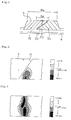
- Fig. 1 is a sectional view of a tire meridian showing one example of a pneumatic tire according to the present invention
- Fig. 2 is an enlarged view showing a substantial part of that.
- the pneumatic tire T comprises a pair of bead portions 1, side wall portions 2 extending from the bead portions 1 to the outer side in a tire diametrical direction, and a tread portion 3 connected to the outer ends in a tire diametrical direction of the side wall portions 2.
- the tire T is an installing direction designated type tire, and is structured such as to designate which of right and left tires faces an outer side of a vehicle, at a time of being installed to a rim 20.
- the tread rubber 5 includes two kinds of rubbers 5o and 5i having different tension moduli, and has a structure which is divided in a tire width direction.
- An interface 10 forming a division surface is formed in the center rib 6 along a tire diametrical direction, the outside rubber 5o having a relatively high tension modulus is arranged at the outside relative to the vehicle, and the inside rubber 5i having a relatively low tension modulus is arranged at the inside relative to the vehicle, by setting the interface 10 to a boundary.
- a tension modulus Mo of the outside rubber 5o and a tension modulus Mi of the inside rubber 5i satisfy a relationship Mo > Mi, and this fact is advantageous for securing a good cornering stability.
- the tension modulus difference (Mo - Mi) between the outside rubber 5o and the inside rubber 5i is set to be equal to or more than 15 % of the tension modulus Mo of the outside rubber 5o, and it is further preferable if it is equal to or more than 25 %. If the tension modulus difference (Mo - Mi) is less than 15 % of the tension modulus Mo, the strain is not moderately prompted in the center rib 6, and the improving effect mentioned above is hard to be sufficiently obtained.
- the region having the small strain as shown in Figs. 4 and 5 tends to be formed in the vicinity of the center position 6C of the center rib 6. Accordingly, it is preferable that the center position 6C is included in the interface region of the center rib 6.
- the interface region is a region which is from an outer peripheral end of the interface 10 in the center rib 6 to an inner peripheral end thereof, and is a region having a width Aw shown in Fig. 2 . Further, it is preferable that the tire equator CL is included in the interface region.
- the strain prompting action of the center rib 6 can be obtained, however, since there is a risk that the durability in the vicinity of the interface 10 is deteriorated in that case, it is preferable to make the width Aw of the interface region of the center rib 6 equal to or more than 25 % of the rib width Rw so as to secure the bonding region of the interface 10. In this case, since a spread in the width direction of the region which is hard to be distorted is limited in the center rib 6, it is preferable that the width Aw is equal to or less than 75 % of the rib width Rw.
- the outside rubber 5o may be integrated with an inner peripheral side portion of the inside rubber 5i.
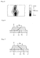
- the interface region in this interface 10 may be defined as a region having the width Aw. Even in the case where the sloping angle of the interface 10 is inverted as shown in Fig. 7 , the same effect can be obtained, and a structure in which the inside rubber 5i is integrated with the inner peripheral side portion of the outside rubber 5o as shown in Fig. 8 may be employed.
- Fig. 9 is an example in which the interface 10 is formed as an approximately S-shaped form in a cross section of the tire meridian, and the interface 10 has a bent portion at the midpoint between an outer peripheral end and an inner peripheral end.
- the region having the small strain tends to be formed as an approximately S-shaped form, and since the tendency is particularly remarkable as the width of the center rib 6 is enlarged, it is possible to enhance the strain prompting action so as to effectively improve the cornering stability and the braking performance, by setting the interface 10 according to the shape along the lines thereof. Further, this structure is advantageous for securing the bonding region of the interface 10.
- the tread rubber may include three kinds or more of rubbers, by setting a division surface in the other land portions other than the center rib.
- a tire size is 265/35R19 98Y, and has the tire structure as shown in Fig. 1 .
- Only the related art is structured such as to be provided with a single layer tread rubber in which the interface is not formed in the center rib. Further, in the Example 3, the interface is formed as an approximately S-shaped form as shown in Fig. 9 .
- Table 1 shows a tension modulus and a rubber hardness of the tread rubber, and respective widths, and Table 2 shows results of evaluation.
- Table 1 300% Tension Modulus (MPa) Rubber Hardness (°) Grounding Width Cw Rib Width Rw Rw/Cw Interface Width Aw Aw/Rw Vehicle Outside Mo Vehicle Inside Mi Mo-Mi (Mo-Mi)Mo Vehicle outside Ho Vehicle inside Hi Ho-Hi Related Art 11.5 - - 75 - 212 24 11% - Example 1 11.5 7.5 4.0 35% 75 78 -3 212 24 11% 12 50% Example 2 11.5 9.5 2.0 17% 75 73 2 212 24 11% 12 50% Example 3 11.5 7.5 4.0 35% 75 78 -3 212 24 11% 12 50% Comparative Example 1 9.5 11.5 2.0 -21% 73 75 -2 212 24 11% 12 50% Comparative Example 2 11.5 10.5 1.0 9% 75 74 1 212 24 11% 12 50% Comparative Example 3 11.5 7.5 4.0 35% 75 71 4 212 24 11% 12 50% Comparative Example 4 11.5 7.5 4.0 35% 75 78 -3 212 19 9% 12 63%
Landscapes
- Engineering & Computer Science (AREA)
- Mechanical Engineering (AREA)
- Tires In General (AREA)
Abstract


Description
- The present invention relates to a pneumatic tire which is provided with a center rib extending along a tire circumferential direction in a center portion of a tread surface.
- In the pneumatic tire having the center rib mentioned above, since the rigidity of the center portion of the tread surface is enhanced, there is a tendency that a travel motion becomes stable even under severe environmental travel conditions (severe travel conditions), and the steering stability at a time of changing lane from a rectilinear travel (hereinafter, referred to as "lane change stability") is improved.
On the other hand, if the center rib is made wide so as to make the rigidity too high, the grounding property with respect to a road surface is deteriorated under such a severe travel condition , for example, at a marginal cornering time, a braking time and the like, whereby a sufficient grip cannot be obtained. Accordingly, the steering stability at a time of cornering (hereinafter, referred to as "cornering stability") and a braking performance are deteriorated. - In brief, there is a tendency that if the center rib is made narrow, the lane change stability is lowered, and if the center rib is made wide, the cornering stability and the braking performance are lowered, and both are in an incompatible relationship with regard to the width of the center rib.
In general, in a tire having a wide grounding width or a tire having a low flattening, since the center rib tends to become wide from a relative relationship to another region of the tread surface, there is a risk that the cornering stability and the braking performance are deteriorated.
On the contrary, there can be considered such a countermeasure for making the center rib low in its rigidity by segmenting with a narrow groove or a sipe or using a soft rubber compounding. However, in that case, the lane change stability is deteriorated. - In a pneumatic tire described in the following
Patent Document 1, a tread band is separated into two sections in a tire width direction, an elastic modulus of a rubber outside a vehicle is set to 12 to 16 MPa, and an elastic modulus of a rubber inside the vehicle is set to 7 to 11 MPa.
However, this is for the purpose of enhancing the steering stability at a time of cornering on a dry road surface by the rubber outside relative to the vehicle, and enhancing the ride comfort and the steering stability on a wet road surface by the rubber inside relative to the vehicle.
In other words, in the tire, it is planned to make an outer side of the tire relative to the vehicle hard, and make an inner side of the tire relative to the vehicle soft, and the rubbers having the different elastic modulus (storage modulus E') are used only for achieving it.
Accordingly, in an actual tire, the rubber having a high hardness is arranged at the outside relative to the vehicle, and the rubber having a low hardness is arranged at the inside relative to the vehicle, necessarily (refer to Tables 1 and 2 of the patent Document 1). - In order to make the lane change stability, and the cornering stability and the braking performance compatible, it is important to improve the grounding property of the center rib under very severe conditions , while maintaining the rigidity of the center rib, however,
Patent Document 1 does not teach any solving means for this at all.
Even if the center rib is provided in the center portion of the tread surface and an interface of the rubbers having the different elastic moduli is formed at a center position of the center rib, in the tire mentioned above, a difference of the rubber hardness is large between the outside of the tire relative to the vehicle and the inside of the tire relative to the vehicle, and a rigidity fluctuation is generated in the center rib. Therefore, there is a risk that the lane change stability is lowered, and the incompatibility phenomenon mentioned above can not be solved. -
- Patent Document 1:
- Japanese National Publication of Translated Version No.
2002-532330 - The present invention is made by taking the actual condition mentioned above into consideration, and an object of the present invention is to provide a pneumatic tire which can achieve an excellent cornering stability and a braking performance while securing a lane change stability.
- The inventors of the present invention have paid attention to the fact that a force heading for a center portion (an in-plane contractive force) acts on a grounding surface of a tire, and a center rib is less deflected and is hard to be distorted.
Further, devoting themselves to make a study, they have found that a region having a particularly small strain is formed in the center rib along a tire diametrical direction, and the strain in a grounding surface side of the center rib can be prompted by forming an interface of rubbers having different tension moduli (JISK6200 01) in the region having the small strain. The present invention is made on the basis of the recognition mentioned above, and can achieve the object mentioned above, with the following structure. - That is, the present invention provides a pneumatic tire comprising a center rib extending along a tire circumferential direction in a center portion of a tread surface,
wherein the width of the center rib is equal to or more than 10 % of a grounding width, an outside rubber having a relatively high tension modulus is arranged at the outside relative to a vehicle and an inside rubber having a relatively low tension modulus is arranged at the inside relative to a vehicle, by setting an interface formed in the center rib along a tire diametrical direction to a boundary, and wherein
300 % tension modulus Mo and a rubber hardness Ho of the outside rubber, and 300 % tension modulus Mi and a rubber hardness Hi of the inside rubber satisfy the following relationship:

- In the present invention, since the width of the center rib is equal to or more than 10 % of the grounding width, the center rib becomes moderately wide so as to be advantageous for securing the lane change stability.
Further, since the rubbers having the different tension modulus are arranged by setting the interface formed in the center rib to the boundary, it is possible to obtain a sufficient grip by prompting the strain in the grounding surface side of the center rib, and improving the grounding property of the center rib at the marginal cornering time and the braking time.
In order to securely achieve the strain prompting action mentioned above, a tension modulus difference (Mo - Mi) between the outside rubber and the inside rubber is set to be equal to or more than 15 % of the 300 % tension modulus Mo of the outside rubber.
Further, in the present invention, in spite of a positive provision of the tension modulus difference as mentioned above, a hardness difference (Ho - Hi) between the outside rubber and the inside rubber is set within 3°, and a rigidity fluctuation of the center rib is suppressed. As a result, it is possible to achieve an excellent cornering stability and braking performance while securing a good lane change stability. - The grounding width is a distance between the outermost positions in a tire axial direction in the center portion in the circumferential direction of the grounding surface, at a time of filling a normal internal pressure in the tire installed to a normal rim so as to place on a flat road surface, and applying a load corresponding to 88 % of a maximum load capacity of the tire.
The normal rim is a rim which is determined per tire by a standard system including a standard on which the tire is based, for example, is a standard rim in JATMA, "Design Rim" in TRA, or "Measuring Rim" in ETRTO.
Further, the normal internal pressure is a pneumatic pressure determined per tire by a standard system including a standard on which the tire is based, and is a maximum pneumatic pressure in JATMA, a maximum value described in Table "TIRE LOAD LIMITS AT VARIOUS COLD INFLATION PRESSURES" in TRA, or "INFLATION PRESSURE" in ETRTO. - In the present invention, it is preferable that the center position of the center rib is included in an interface region of the center rib. Since the region having the small strain in the center rib tends to be particularly formed at the center position of the center rib, it is possible to accurately achieve the strain prompting action with respect to the center rib by setting the interface region as mentioned above, whereby it is possible to effectively improve the cornering stability and the braking performance.
- In the present invention, it is preferable that a width of an interface region of the center rib is equal to or more than 25 % of a width of the center rib. According to the structure mentioned above, since it is possible to secure the bonding region of the interface so as to prevent a crack or the like in the interface, while maintaining the strain prompting action with respect to the center rib, it becomes advantageous for securing the durability.
-
- Fig. 1
- is a sectional view of a tire meridian showing one example of a pneumatic tire according to the present invention;
- Fig. 2
- is an enlarged view showing a substantial part of
Fig. 1 ; - Fig. 3
- is a contour view conceptually showing a distribution of a strain in a cross section of a center rib;
- Fig. 4
- is a contour view of a strain distribution in a single layered center rib which is shown for comparing with the present invention;
- Fig. 5
- is a contour view of a strain distribution in a single layered center rib which is shown for comparing with the present invention;
- Fig. 6
- is a cross sectional view of a center rib according to another embodiment of the present invention;
- Fig. 7
- is a cross sectional view of a center rib according to still another embodiment of the present invention;
- Fig. 8
- is a cross sectional view of a center rib according to a further embodiment of the present invention;
- Fig. 9
- is a cross sectional view of a center rib according to yet another embodiment of the present invention.
- An embodiment of the present invention will be explained with reference to the drawings.
Fig. 1 is a sectional view of a tire meridian showing one example of a pneumatic tire according to the present invention, andFig. 2 is an enlarged view showing a substantial part of that.
The pneumatic tire T comprises a pair ofbead portions 1,side wall portions 2 extending from thebead portions 1 to the outer side in a tire diametrical direction, and a tread portion 3 connected to the outer ends in a tire diametrical direction of theside wall portions 2.
The tire T is an installing direction designated type tire, and is structured such as to designate which of right and left tires faces an outer side of a vehicle, at a time of being installed to arim 20. - A
carcass layer 4 includes a ply which is interlinked between a pair ofbead portions 1, and a tread rubber 5 is arranged in an outer periphery of the tread portion 3. The pneumatic tire T has the same tire structure as that of a conventional one except for the structure of the tread rubber 5 which will be in detailed described below, and the material, the shape and the like which have been known conventionally can be employed in the present invention without any particular limitation.
Although an illustration is omitted, a belt layer including two belt plies which are laminated inside and outside is laminated in an outer periphery of thecarcass layer 4, in the tread portion 3, and a belt reinforcing layer is further laminated in an outer periphery thereof. - A center portion of the tread surface is provided with a
center rib 6 extending along a tire circumferential direction . Thecenter rib 6 is provided in a region which is 10 % of a grounding width Cw in both right and left sides (totally 20 %) on the basis of a tire equator line CL. A width Rw of thecenter rib 6 is set to be equal to or more than 10 % of the grounding width Cw.
Accordingly, thecenter rib 6 becomes moderately wide, thereby becoming advantageous for securing a lane change stability. This rib width Rw is measured in the grounding surface in the same measuring condition as that of the grounding width Cw, and is equal to or less than 20 % of the grounding width Cw at most. - The tread rubber 5 includes two kinds of
rubbers 5o and 5i having different tension moduli, and has a structure which is divided in a tire width direction. Aninterface 10 forming a division surface is formed in thecenter rib 6 along a tire diametrical direction, the outside rubber 5o having a relatively high tension modulus is arranged at the outside relative to the vehicle, and theinside rubber 5i having a relatively low tension modulus is arranged at the inside relative to the vehicle, by setting theinterface 10 to a boundary.
In other words, a tension modulus Mo of the outside rubber 5o and a tension modulus Mi of theinside rubber 5i satisfy a relationship Mo > Mi, and this fact is advantageous for securing a good cornering stability. - In the present invention, the tension moduli Mo and Mi are set in such a manner as to satisfy a relationship (Mo - Mi)/Mo ≥ 0.15, and a rubber hardness Ho of the outside rubber 5o and a rubber hardness Hi of the
inside rubber 5i are set in such a manner as to satisfy a relationship Ho - Hit ≤ ± 3°.
The tension modulus Mo and Mi are 300 % tension modulus which is measured at 25 °C according to JISK6251, and the rubber hardness Ho and Hi are a rubber hardness which is measured at 25 °C by a durometer hardness tester (type A) of JISK6253. - It is possible to prompt a strain in the grounding surface side of the
center rib 6 as shown inFig. 3 at a time of grounding, by setting theinterface 10 in thecenter rib 6. On the contrary, in the case where thecenter rib 6 includes a single layer of the outside rubber 5o (Fig. 4 ), and in the case where it includes a single layer of theinside rubber 5i (Fig. 5 ), a region which is hard to be distorted is formed along a tire diametrical direction.
In other words, in the case where the region in which the strain becomes small in the center rib of the single layer forms theinterface 10 of the rubbers having the different tension modulus, the strain is prompted in the grounding surface side of thecenter rib 6 as shown inFig. 3 . - Here,
Figs. 3 to 5 are contour views of a strain amplitude in the cross section of the center rib, and mean that the strain amplitude is large in a pale region, and the strain is prompted. In this case, this strain amplitude is an amplitude of a shear strain in "back and forth - width direction" in a total coordinate system, and this "back and forth - width direction" coincides with "circumferential - meridian direction" in a local coordinate system on a tire body.
The amplitude of a strain acting on the center portion of thecenter rib 6 of the tire T is approximately equal to or less than 2 %, however, in such a region that the strain amplitude is small (less than about 3 %), there is a tendency that tan δ (a loss factor) becomes generally larger according to an enlargement of the strain amplitude (for example, refer to Fig. 4.15(b) in page 84 of "New Edition Base of Rubber Technique" issued by Society of Rubber Industry, Japan). Accordingly, it is possible to enhance a grip by prompting the strain. - Therefore, in the tire T, since a sufficient grip can be obtained by prompting the strain in the grounding surface side of the
center rib 6 and improving the grounding property, at the marginal cornering time and the braking time, it is possible to achieve the excellent cornering stability and braking performance.
In the present invention, in order to securely generate the strain prompting action mentioned above, the tension modulus difference (Mo - Mi) between the outside rubber 5o and theinside rubber 5i is set to be equal to or more than 15 % of the tension modulus Mo of the outside rubber 5o, and it is further preferable if it is equal to or more than 25 %.
If the tension modulus difference (Mo - Mi) is less than 15 % of the tension modulus Mo, the strain is not moderately prompted in thecenter rib 6, and the improving effect mentioned above is hard to be sufficiently obtained. - As mentioned above, since the outside rubber 5o and the
inside rubber 5i are provided with the tension modulus difference which is equal to or more than a predetermined level, even if the rib width Rw is set to be equal to or more than 10 % of the grounding width Cw, this setting is not sufficient for securing the lane change stability.
Accordingly, in the present invention, the hardness difference (Ho - Hi) is set within ± 3° while positively setting the tension modulus difference with respect to the outside rubber 5o and theinside rubber 5i, thereby suppressing the rigidity fluctuation of thecenter rib 6. As a result, it is possible to achieve excellent cornering stability and braking performance while securing a lane change stability. - The region having the small strain as shown in
Figs. 4 and5 tends to be formed in the vicinity of thecenter position 6C of thecenter rib 6. Accordingly, it is preferable that thecenter position 6C is included in the interface region of thecenter rib 6. The interface region is a region which is from an outer peripheral end of theinterface 10 in thecenter rib 6 to an inner peripheral end thereof, and is a region having a width Aw shown inFig. 2 . Further, it is preferable that the tire equator CL is included in the interface region. - Even in the case where the
interface 10 is formed in parallel to the tire diametrical direction, the strain prompting action of thecenter rib 6 can be obtained, however, since there is a risk that the durability in the vicinity of theinterface 10 is deteriorated in that case, it is preferable to make the width Aw of the interface region of thecenter rib 6 equal to or more than 25 % of the rib width Rw so as to secure the bonding region of theinterface 10.
In this case, since a spread in the width direction of the region which is hard to be distorted is limited in thecenter rib 6, it is preferable that the width Aw is equal to or less than 75 % of the rib width Rw. - In the present embodiment, since the
interface 10 is inclined with respect to the tire diametrical direction and extends linearly, it is possible to moderately secure the width Aw of the interface region, and it is possible to more securely prompt the strain in the grounding surface side of thecenter rib 6.
Above and below theinterface 10, theinside rubber 5i is arranged in the grounding surface side, however, the outside rubber 5o may be arranged in the grounding surface side by inverting the direction of slope of theinterface 10, and the same effect can be obtained even in that case. - The tension modulus Mo of the outside rubber 5o is, for example, between 10 and 20 MPa, and the tension modulus Mi of the
inside rubber 5i is, for example, between 5 and 15 MPa. Further, it is preferable that each of the rubber hardness Ho of the outside rubber 5o and the rubber hardness Hi of theinside rubber 5i is between 70° and 80°, for securing the lane change stability. - The present invention is not limited to the embodiment mentioned above, but can be variously modified and changed within the scope of the present invention. The tread pattern included in the pneumatic tire according to the present invention is not particularly limited as long as the center rib is provided as mentioned above, but may be any of a symmetrical pattern or an asymmetrical pattern.
- Since even in the case where the center rib becomes wide for a design reason or the like, the pneumatic tire according to the present invention can generate the operation and effect as mentioned above so as to cope therewith, , it is particularly useful in the tire having a low flattening.
- (1) In the present invention, as shown in
Fig. 6 , the outside rubber 5o may be integrated with an inner peripheral side portion of theinside rubber 5i. According to the structure mentioned above, it is possible to well enhance a steering stability at the marginal cornering time at which the severity is comparatively high. The interface region in thisinterface 10 may be defined as a region having the width Aw.
Even in the case where the sloping angle of theinterface 10 is inverted as shown inFig. 7 , the same effect can be obtained, and a structure in which theinside rubber 5i is integrated with the inner peripheral side portion of the outside rubber 5o as shown inFig. 8 may be employed. - (2)
Fig. 9 is an example in which theinterface 10 is formed as an approximately S-shaped form in a cross section of the tire meridian, and theinterface 10 has a bent portion at the midpoint between an outer peripheral end and an inner peripheral end.
As shown byFigs. 4 and5 , the region having the small strain tends to be formed as an approximately S-shaped form, and since the tendency is particularly remarkable as the width of thecenter rib 6 is enlarged, it is possible to enhance the strain prompting action so as to effectively improve the cornering stability and the braking performance, by setting theinterface 10 according to the shape along the lines thereof. Further, this structure is advantageous for securing the bonding region of theinterface 10. - (3) It is preferable that a narrow groove (a notch or a slit) and a sipe cutting across the center rib are not formed in the center rib. But, no obstacle is generated even if a narrow groove or a sipe are formed, as long as it neither comparts the center rib nor interferes with the interface.
- (4) In the present invention, if the interface as mentioned above is formed in the center rib, the tread rubber may include three kinds or more of rubbers, by setting a division surface in the other land portions other than the center rib.
- An example tire which concretely shows the structure and effect of the present invention will be explained. An evaluation of each of performances for tire is executed as follows.
- The pneumatic tire was installed to a rim of 19 x 9J and was filled with a pneumatic pressure in the order of 260 kPa, and a subjective evaluation (on a scale of one to ten) with respect to the lane change stability and the cornering stability was carried out, under a load condition that a driver and the other one (totally two persons) got on an actual car (a domestic 3000 cm3 car).
With regard to the former, the steering property and a response were evaluated at a time of carrying out a lane change travel from a rectilinear travel at 100 to 150 km/h, in a flat straight portion of a high-speed orbiting test course. With regard to the latter, the gripping force and the stability were evaluated at a time of carrying out a high severity travel focusing on a marginal behavior, in a handling test course having a lot of corners which are variously different in their cornering radii. Both are expressed by index numbers in which a related art is set to 100, and the greater numerical value indicates the better performance. - The pneumatic tire was installed to a rim of 19 x 9J and was filled with a pneumatic pressure in the order of 260 kPa, a braking distance was measured at a time of slowing down from 100 km/h to 0 km/h on a dry road surface, under a load condition that a driver and the other one (totally two persons) got on an actual car (a domestic 3000 cm3 car), and an inverse number thereof was calculated. An evaluation is shown by index numbers in which the related art is set to 100, and the greater numerical value indicates the better performance.
- In all the test tires of each of the examples, a tire size is 265/35R19 98Y, and has the tire structure as shown in
Fig. 1 . Only the related art is structured such as to be provided with a single layer tread rubber in which the interface is not formed in the center rib. Further, in the Example 3, the interface is formed as an approximately S-shaped form as shown inFig. 9 . Table 1 shows a tension modulus and a rubber hardness of the tread rubber, and respective widths, and Table 2 shows results of evaluation. -
Table 1 300% Tension Modulus (MPa) Rubber Hardness (°) Grounding Width Cw Rib Width Rw Rw/Cw Interface Width Aw Aw/Rw Vehicle Outside Mo Vehicle Inside Mi Mo-Mi (Mo-Mi)Mo Vehicle outside Ho Vehicle inside Hi Ho-Hi Related Art 11.5 - - 75 - 212 24 11% - Example 1 11.5 7.5 4.0 35% 75 78 -3 212 24 11% 12 50% Example 2 11.5 9.5 2.0 17% 75 73 2 212 24 11% 12 50% Example 3 11.5 7.5 4.0 35% 75 78 -3 212 24 11% 12 50% Comparative Example 1 9.5 11.5 2.0 -21% 73 75 -2 212 24 11% 12 50% Comparative Example 2 11.5 10.5 1.0 9% 75 74 1 212 24 11% 12 50% Comparative Example 3 11.5 7.5 4.0 35% 75 71 4 212 24 11% 12 50% Comparative Example 4 11.5 7.5 4.0 35% 75 78 -3 212 19 9% 12 63% -
Table 2 Steering Stability Braking Performance Lane Change Cornering Related Art 100 100 100 Example 1 100 107 103 Example 2 100 103 101 Example 3 100 110 105 Comparative Example 1 100 97 101 Comparative Example 2 100 100 100 Comparative Example 3 98 107 103 Comparative Example 4 95 102 101 - In the Comparative Example 1, since the outside rubber has the lower tension modulus than the inside rubber, the cornering stability cannot be secured.
In the Comparative Example 2, since the tension modulus difference between the outside rubber and the inside rubber is small, it is thought that the strain prompting action in the center rib is not sufficient.
In the Comparative Example 3, since the hardness difference between the outside rubber and the inside rubber is large, the rigidity fluctuation is generated in the center rib, and the lane change stability can not be secured.
In the Comparative Example 4, since the width of the center rib is not sufficiently secured, the lane change stability can not be secured.
On the contrary, in the Examples 1 to 3, it is possible to achieve an excellent cornering stability and braking performance while securing the lane change stability. -
- 1
- bead portion
- 2
- side wall portion
- 3
- tread portion
- 4
- carcass layer
- 5
- tread rubber
- 5i
- inside rubber
- 5o
- outside rubber
- 6
- center rib
- 6C
- center position
- 10
- interface
- Aw
- width of interface region
- Cw
- grounding width
- Rw
- width of center rib
Claims (8)
- A pneumatic tire comprising a center rib extending along a tire circumferential direction in a center portion of a tread surface,
wherein the width of the center rib is equal to or more than 10 % of a grounding width, an outside rubber having a relatively high tension modulus is arranged at the outside relative to a vehicle and an inside rubber having a relatively low tension modulus is arranged at the inside relative to a vehicle, by setting an interface formed in the center rib along a tire diametrical direction to a boundary, and
wherein 300 % tension modulus Mo and a rubber hardness Ho of the outside rubber, and 300 % tension modulus Mi and a rubber hardness Hi of the inside rubber satisfy the following relationship:

- The pneumatic tire according to claim 1,
wherein a center position of the center rib is included in an interface region of the center rib. - The pneumatic tire according to claim 1,
wherein a width of an interface region of the center rib is equal to or more than 25 % of a width of the center rib. - The pneumatic tire according to claim 1,
wherein the relationship (Mo - Mi)/Mo ≥ 0.25 is satisfied. - The pneumatic tire according to claim 1,
wherein the 300 % tension modulus Mo of the outside rubber is between 10 MPa and 20 MPa, and the 300 % tension modulus Mi of the inside rubber is between 5 MPa and 15 MPa. - The pneumatic tire according to claim 1,
wherein each of the rubber hardness Ho of the outside rubber and the rubber hardness Hi of the inside rubber is between 70° and 80°. - The pneumatic tire according to claim 1,
wherein the outside rubber is integrated with an inner peripheral side portion of the inside rubber. - The pneumatic tire according to claim 1,
wherein the interface is formed as an approximately S-shaped form in a tire meridian cross section, and has a bent portion at the midpoint of an outer peripheral end and an inner peripheral end.
Applications Claiming Priority (2)
| Application Number | Priority Date | Filing Date | Title |
|---|---|---|---|
| JP2009131336A JP4527180B1 (en) | 2009-05-29 | 2009-05-29 | Pneumatic tire |
| PCT/JP2010/052976 WO2010122840A1 (en) | 2009-05-29 | 2010-02-25 | Pneumatic tire |
Publications (3)
| Publication Number | Publication Date |
|---|---|
| EP2289713A1 true EP2289713A1 (en) | 2011-03-02 |
| EP2289713A4 EP2289713A4 (en) | 2011-06-29 |
| EP2289713B1 EP2289713B1 (en) | 2012-09-26 |
Family
ID=42767862
Family Applications (1)
| Application Number | Title | Priority Date | Filing Date |
|---|---|---|---|
| EP10765355A Active EP2289713B1 (en) | 2009-05-29 | 2010-02-25 | Pneumatic tire |
Country Status (5)
| Country | Link |
|---|---|
| US (1) | US9193216B2 (en) |
| EP (1) | EP2289713B1 (en) |
| JP (1) | JP4527180B1 (en) |
| CN (1) | CN102026827B (en) |
| WO (1) | WO2010122840A1 (en) |
Families Citing this family (14)
| Publication number | Priority date | Publication date | Assignee | Title |
|---|---|---|---|---|
| JP5973142B2 (en) * | 2011-08-09 | 2016-08-23 | 東洋ゴム工業株式会社 | Vehicle tire mounting structure |
| US9463670B2 (en) * | 2011-10-04 | 2016-10-11 | The Yokohama Rubber Co., Ltd. | Pneumatic tire |
| JP5992204B2 (en) * | 2012-05-18 | 2016-09-14 | 東洋ゴム工業株式会社 | Pneumatic tire |
| JP6091006B2 (en) * | 2013-09-30 | 2017-03-08 | 東洋ゴム工業株式会社 | Pneumatic tire manufacturing method and pneumatic tire |
| JP6370180B2 (en) * | 2014-09-18 | 2018-08-08 | 東洋ゴム工業株式会社 | Pneumatic tire |
| JP6540915B1 (en) * | 2017-11-20 | 2019-07-10 | 横浜ゴム株式会社 | Pneumatic tire |
| JP2019111860A (en) | 2017-12-21 | 2019-07-11 | Toyo Tire株式会社 | Pneumatic tire |
| JP6993865B2 (en) * | 2017-12-21 | 2022-02-10 | Toyo Tire株式会社 | Pneumatic tires |
| FR3090656A3 (en) * | 2018-12-21 | 2020-06-26 | Michelin & Cie | Tire tread |
| CN110341383A (en) * | 2019-07-17 | 2019-10-18 | 江苏通用科技股份有限公司 | A kind of eccentric abrasion prevention tread structure |
| FR3104067A1 (en) * | 2019-12-04 | 2021-06-11 | Compagnie Generale Des Etablissements Michelin | Advanced tread tire |
| JP7675514B2 (en) * | 2020-11-20 | 2025-05-13 | 株式会社ブリヂストン | tire |
| US12252127B2 (en) * | 2022-04-19 | 2025-03-18 | Aptiv Technologies AG | Dynamically calculating lane change trajectories |
| JP2025000378A (en) * | 2023-06-19 | 2025-01-07 | 住友ゴム工業株式会社 | tire |
Family Cites Families (19)
| Publication number | Priority date | Publication date | Assignee | Title |
|---|---|---|---|---|
| JP2728286B2 (en) * | 1989-01-12 | 1998-03-18 | 株式会社ブリヂストン | Pneumatic radial tire |
| JP2912437B2 (en) * | 1990-09-25 | 1999-06-28 | 株式会社ブリヂストン | Pneumatic radial tire |
| JPH04185507A (en) * | 1990-11-21 | 1992-07-02 | Yokohama Rubber Co Ltd:The | Pneumatic radial tire |
| DE4447823B4 (en) * | 1994-12-21 | 2007-07-26 | Dunlop Gmbh | Vehicle tires and process for its manufacture |
| US6523585B1 (en) * | 1997-03-18 | 2003-02-25 | Bridgestone Corporation | Antistatic tire |
| JPH11139107A (en) * | 1997-09-02 | 1999-05-25 | Bridgestone Corp | Pneumatic tire |
| JP4071354B2 (en) | 1998-05-07 | 2008-04-02 | 東洋ゴム工業株式会社 | Pneumatic radial tire |
| TW482732B (en) | 1998-12-21 | 2002-04-11 | Pirelli | Dual composition tread band for tire |
| KR100624121B1 (en) | 1998-12-21 | 2006-09-19 | 피렐리 타이어 소시에떼 퍼 아찌오니 | Dual structure tread band for tire |
| DE10042241A1 (en) * | 2000-08-28 | 2002-03-14 | Dunlop Gmbh | vehicle tires |
| US6780925B2 (en) * | 2001-12-21 | 2004-08-24 | The Goodyear Tire & Rubber Company | Rubber composition with silica reinforcement obtained with an amino acid or amino acid-containing protein based activator and use thereof in tires |
| KR100396486B1 (en) * | 2002-01-19 | 2003-10-22 | 금호산업주식회사 | Tire Tread Structure of Electric Discharge |
| JP2003326917A (en) * | 2002-05-10 | 2003-11-19 | Toyo Tire & Rubber Co Ltd | Pneumatic radial tire |
| US7028734B2 (en) * | 2003-06-24 | 2006-04-18 | The Goodyear Tire & Rubber Company | Truck tire with cap/base construction tread |
| EP1619048B1 (en) * | 2004-07-15 | 2013-09-11 | Continental Reifen Deutschland GmbH | Pneumatic vehicle tire |
| JP4457388B2 (en) * | 2005-02-08 | 2010-04-28 | 東洋ゴム工業株式会社 | Run flat tire |
| JP4639859B2 (en) * | 2005-03-07 | 2011-02-23 | 横浜ゴム株式会社 | Pneumatic tire |
| JP4569384B2 (en) * | 2005-05-23 | 2010-10-27 | 横浜ゴム株式会社 | Pneumatic tire |
| US7789117B2 (en) * | 2006-01-27 | 2010-09-07 | The Goodyear Tire & Rubber Company | Tire with circumferential rubber tread having a lateral outboard control element |
-
2009
- 2009-05-29 JP JP2009131336A patent/JP4527180B1/en active Active
-
2010
- 2010-02-25 US US12/920,364 patent/US9193216B2/en not_active Expired - Fee Related
- 2010-02-25 CN CN2010800015223A patent/CN102026827B/en active Active
- 2010-02-25 EP EP10765355A patent/EP2289713B1/en active Active
- 2010-02-25 WO PCT/JP2010/052976 patent/WO2010122840A1/en not_active Ceased
Also Published As
| Publication number | Publication date |
|---|---|
| WO2010122840A1 (en) | 2010-10-28 |
| US20110048600A1 (en) | 2011-03-03 |
| JP4527180B1 (en) | 2010-08-18 |
| EP2289713B1 (en) | 2012-09-26 |
| CN102026827B (en) | 2013-09-11 |
| EP2289713A4 (en) | 2011-06-29 |
| US9193216B2 (en) | 2015-11-24 |
| JP2010274853A (en) | 2010-12-09 |
| CN102026827A (en) | 2011-04-20 |
Similar Documents
| Publication | Publication Date | Title |
|---|---|---|
| EP2289713B1 (en) | Pneumatic tire | |
| EP3205516B1 (en) | Pneumatic tire | |
| EP2423005B1 (en) | Pneumatic tire | |
| CN101595003B (en) | Pneumatic tire | |
| CN104837650B (en) | The tire of the tyre surface including being made up of multiple elastomer blends | |
| EP2060413B1 (en) | Tire for construction vehicle | |
| EP2581238B1 (en) | Heavy duty tire | |
| US9340074B2 (en) | Pneumatic tire with specified rim strip rubber arrangement | |
| CN108136843B (en) | Pneumatic tire | |
| CN104349915A (en) | Pneumatic tire | |
| CN104822542A (en) | Tyre comprising tread made up of several elastomeric compounds | |
| EP3332991A1 (en) | Pneumatic tire | |
| JP4776622B2 (en) | Construction vehicle tires | |
| EP3800070B1 (en) | Heavy duty pneumatic tire | |
| JP4436146B2 (en) | Passenger car tires | |
| EP2213480B1 (en) | Pneumatic tire | |
| CN108367620A (en) | Tires with improved wear and rolling resistance properties | |
| CN108025601B (en) | Pneumatic tire | |
| CN111989230B (en) | Pneumatic tire | |
| JP2024080007A (en) | Heavy duty pneumatic tires | |
| CN108367612A (en) | Tire with improved polishing machine and improved rolling resistance | |
| CN115431677A (en) | Heavy load pneumatic tire |
Legal Events
| Date | Code | Title | Description |
|---|---|---|---|
| PUAI | Public reference made under article 153(3) epc to a published international application that has entered the european phase |
Free format text: ORIGINAL CODE: 0009012 |
|
| 17P | Request for examination filed |
Effective date: 20101021 |
|
| AK | Designated contracting states |
Kind code of ref document: A1 Designated state(s): AT BE BG CH CY CZ DE DK EE ES FI FR GB GR HR HU IE IS IT LI LT LU LV MC MK MT NL NO PL PT RO SE SI SK SM TR |
|
| AX | Request for extension of the european patent |
Extension state: AL BA RS |
|
| A4 | Supplementary search report drawn up and despatched |
Effective date: 20110527 |
|
| GRAP | Despatch of communication of intention to grant a patent |
Free format text: ORIGINAL CODE: EPIDOSNIGR1 |
|
| DAX | Request for extension of the european patent (deleted) | ||
| GRAS | Grant fee paid |
Free format text: ORIGINAL CODE: EPIDOSNIGR3 |
|
| GRAA | (expected) grant |
Free format text: ORIGINAL CODE: 0009210 |
|
| AK | Designated contracting states |
Kind code of ref document: B1 Designated state(s): AT BE BG CH CY CZ DE DK EE ES FI FR GB GR HR HU IE IS IT LI LT LU LV MC MK MT NL NO PL PT RO SE SI SK SM TR |
|
| REG | Reference to a national code |
Ref country code: GB Ref legal event code: FG4D |
|
| REG | Reference to a national code |
Ref country code: CH Ref legal event code: EP |
|
| REG | Reference to a national code |
Ref country code: AT Ref legal event code: REF Ref document number: 576855 Country of ref document: AT Kind code of ref document: T Effective date: 20121015 |
|
| REG | Reference to a national code |
Ref country code: IE Ref legal event code: FG4D |
|
| REG | Reference to a national code |
Ref country code: DE Ref legal event code: R096 Ref document number: 602010002997 Country of ref document: DE Effective date: 20121115 |
|
| PG25 | Lapsed in a contracting state [announced via postgrant information from national office to epo] |
Ref country code: FI Free format text: LAPSE BECAUSE OF FAILURE TO SUBMIT A TRANSLATION OF THE DESCRIPTION OR TO PAY THE FEE WITHIN THE PRESCRIBED TIME-LIMIT Effective date: 20120926 Ref country code: LT Free format text: LAPSE BECAUSE OF FAILURE TO SUBMIT A TRANSLATION OF THE DESCRIPTION OR TO PAY THE FEE WITHIN THE PRESCRIBED TIME-LIMIT Effective date: 20120926 Ref country code: NO Free format text: LAPSE BECAUSE OF FAILURE TO SUBMIT A TRANSLATION OF THE DESCRIPTION OR TO PAY THE FEE WITHIN THE PRESCRIBED TIME-LIMIT Effective date: 20121226 Ref country code: HR Free format text: LAPSE BECAUSE OF FAILURE TO SUBMIT A TRANSLATION OF THE DESCRIPTION OR TO PAY THE FEE WITHIN THE PRESCRIBED TIME-LIMIT Effective date: 20120926 |
|
| REG | Reference to a national code |
Ref country code: AT Ref legal event code: MK05 Ref document number: 576855 Country of ref document: AT Kind code of ref document: T Effective date: 20120926 |
|
| REG | Reference to a national code |
Ref country code: LT Ref legal event code: MG4D Effective date: 20120926 |
|
| REG | Reference to a national code |
Ref country code: NL Ref legal event code: VDEP Effective date: 20120926 |
|
| PG25 | Lapsed in a contracting state [announced via postgrant information from national office to epo] |
Ref country code: SE Free format text: LAPSE BECAUSE OF FAILURE TO SUBMIT A TRANSLATION OF THE DESCRIPTION OR TO PAY THE FEE WITHIN THE PRESCRIBED TIME-LIMIT Effective date: 20120926 Ref country code: SI Free format text: LAPSE BECAUSE OF FAILURE TO SUBMIT A TRANSLATION OF THE DESCRIPTION OR TO PAY THE FEE WITHIN THE PRESCRIBED TIME-LIMIT Effective date: 20120926 Ref country code: GR Free format text: LAPSE BECAUSE OF FAILURE TO SUBMIT A TRANSLATION OF THE DESCRIPTION OR TO PAY THE FEE WITHIN THE PRESCRIBED TIME-LIMIT Effective date: 20121227 Ref country code: LV Free format text: LAPSE BECAUSE OF FAILURE TO SUBMIT A TRANSLATION OF THE DESCRIPTION OR TO PAY THE FEE WITHIN THE PRESCRIBED TIME-LIMIT Effective date: 20120926 |
|
| PG25 | Lapsed in a contracting state [announced via postgrant information from national office to epo] |
Ref country code: CZ Free format text: LAPSE BECAUSE OF FAILURE TO SUBMIT A TRANSLATION OF THE DESCRIPTION OR TO PAY THE FEE WITHIN THE PRESCRIBED TIME-LIMIT Effective date: 20120926 Ref country code: ES Free format text: LAPSE BECAUSE OF FAILURE TO SUBMIT A TRANSLATION OF THE DESCRIPTION OR TO PAY THE FEE WITHIN THE PRESCRIBED TIME-LIMIT Effective date: 20130106 Ref country code: BE Free format text: LAPSE BECAUSE OF FAILURE TO SUBMIT A TRANSLATION OF THE DESCRIPTION OR TO PAY THE FEE WITHIN THE PRESCRIBED TIME-LIMIT Effective date: 20120926 Ref country code: NL Free format text: LAPSE BECAUSE OF FAILURE TO SUBMIT A TRANSLATION OF THE DESCRIPTION OR TO PAY THE FEE WITHIN THE PRESCRIBED TIME-LIMIT Effective date: 20120926 Ref country code: IS Free format text: LAPSE BECAUSE OF FAILURE TO SUBMIT A TRANSLATION OF THE DESCRIPTION OR TO PAY THE FEE WITHIN THE PRESCRIBED TIME-LIMIT Effective date: 20130126 Ref country code: RO Free format text: LAPSE BECAUSE OF FAILURE TO SUBMIT A TRANSLATION OF THE DESCRIPTION OR TO PAY THE FEE WITHIN THE PRESCRIBED TIME-LIMIT Effective date: 20120926 Ref country code: EE Free format text: LAPSE BECAUSE OF FAILURE TO SUBMIT A TRANSLATION OF THE DESCRIPTION OR TO PAY THE FEE WITHIN THE PRESCRIBED TIME-LIMIT Effective date: 20120926 |
|
| PG25 | Lapsed in a contracting state [announced via postgrant information from national office to epo] |
Ref country code: PT Free format text: LAPSE BECAUSE OF FAILURE TO SUBMIT A TRANSLATION OF THE DESCRIPTION OR TO PAY THE FEE WITHIN THE PRESCRIBED TIME-LIMIT Effective date: 20130128 Ref country code: PL Free format text: LAPSE BECAUSE OF FAILURE TO SUBMIT A TRANSLATION OF THE DESCRIPTION OR TO PAY THE FEE WITHIN THE PRESCRIBED TIME-LIMIT Effective date: 20120926 Ref country code: SK Free format text: LAPSE BECAUSE OF FAILURE TO SUBMIT A TRANSLATION OF THE DESCRIPTION OR TO PAY THE FEE WITHIN THE PRESCRIBED TIME-LIMIT Effective date: 20120926 |
|
| PG25 | Lapsed in a contracting state [announced via postgrant information from national office to epo] |
Ref country code: AT Free format text: LAPSE BECAUSE OF FAILURE TO SUBMIT A TRANSLATION OF THE DESCRIPTION OR TO PAY THE FEE WITHIN THE PRESCRIBED TIME-LIMIT Effective date: 20120926 |
|
| PG25 | Lapsed in a contracting state [announced via postgrant information from national office to epo] |
Ref country code: BG Free format text: LAPSE BECAUSE OF FAILURE TO SUBMIT A TRANSLATION OF THE DESCRIPTION OR TO PAY THE FEE WITHIN THE PRESCRIBED TIME-LIMIT Effective date: 20121226 Ref country code: DK Free format text: LAPSE BECAUSE OF FAILURE TO SUBMIT A TRANSLATION OF THE DESCRIPTION OR TO PAY THE FEE WITHIN THE PRESCRIBED TIME-LIMIT Effective date: 20120926 |
|
| PLBE | No opposition filed within time limit |
Free format text: ORIGINAL CODE: 0009261 |
|
| STAA | Information on the status of an ep patent application or granted ep patent |
Free format text: STATUS: NO OPPOSITION FILED WITHIN TIME LIMIT |
|
| PG25 | Lapsed in a contracting state [announced via postgrant information from national office to epo] |
Ref country code: IT Free format text: LAPSE BECAUSE OF FAILURE TO SUBMIT A TRANSLATION OF THE DESCRIPTION OR TO PAY THE FEE WITHIN THE PRESCRIBED TIME-LIMIT Effective date: 20120926 |
|
| 26N | No opposition filed |
Effective date: 20130627 |
|
| PG25 | Lapsed in a contracting state [announced via postgrant information from national office to epo] |
Ref country code: MC Free format text: LAPSE BECAUSE OF NON-PAYMENT OF DUE FEES Effective date: 20130228 |
|
| REG | Reference to a national code |
Ref country code: DE Ref legal event code: R097 Ref document number: 602010002997 Country of ref document: DE Effective date: 20130627 |
|
| REG | Reference to a national code |
Ref country code: FR Ref legal event code: ST Effective date: 20131031 |
|
| PG25 | Lapsed in a contracting state [announced via postgrant information from national office to epo] |
Ref country code: CY Free format text: LAPSE BECAUSE OF FAILURE TO SUBMIT A TRANSLATION OF THE DESCRIPTION OR TO PAY THE FEE WITHIN THE PRESCRIBED TIME-LIMIT Effective date: 20120926 |
|
| REG | Reference to a national code |
Ref country code: IE Ref legal event code: MM4A |
|
| PG25 | Lapsed in a contracting state [announced via postgrant information from national office to epo] |
Ref country code: IE Free format text: LAPSE BECAUSE OF NON-PAYMENT OF DUE FEES Effective date: 20130225 Ref country code: FR Free format text: LAPSE BECAUSE OF NON-PAYMENT OF DUE FEES Effective date: 20130228 |
|
| PG25 | Lapsed in a contracting state [announced via postgrant information from national office to epo] |
Ref country code: MT Free format text: LAPSE BECAUSE OF FAILURE TO SUBMIT A TRANSLATION OF THE DESCRIPTION OR TO PAY THE FEE WITHIN THE PRESCRIBED TIME-LIMIT Effective date: 20120926 |
|
| REG | Reference to a national code |
Ref country code: CH Ref legal event code: PL |
|
| GBPC | Gb: european patent ceased through non-payment of renewal fee |
Effective date: 20140225 |
|
| PG25 | Lapsed in a contracting state [announced via postgrant information from national office to epo] |
Ref country code: CH Free format text: LAPSE BECAUSE OF NON-PAYMENT OF DUE FEES Effective date: 20140228 Ref country code: LI Free format text: LAPSE BECAUSE OF NON-PAYMENT OF DUE FEES Effective date: 20140228 |
|
| PG25 | Lapsed in a contracting state [announced via postgrant information from national office to epo] |
Ref country code: GB Free format text: LAPSE BECAUSE OF NON-PAYMENT OF DUE FEES Effective date: 20140225 |
|
| PG25 | Lapsed in a contracting state [announced via postgrant information from national office to epo] |
Ref country code: SM Free format text: LAPSE BECAUSE OF FAILURE TO SUBMIT A TRANSLATION OF THE DESCRIPTION OR TO PAY THE FEE WITHIN THE PRESCRIBED TIME-LIMIT Effective date: 20120926 |
|
| PG25 | Lapsed in a contracting state [announced via postgrant information from national office to epo] |
Ref country code: TR Free format text: LAPSE BECAUSE OF FAILURE TO SUBMIT A TRANSLATION OF THE DESCRIPTION OR TO PAY THE FEE WITHIN THE PRESCRIBED TIME-LIMIT Effective date: 20120926 |
|
| PG25 | Lapsed in a contracting state [announced via postgrant information from national office to epo] |
Ref country code: LU Free format text: LAPSE BECAUSE OF NON-PAYMENT OF DUE FEES Effective date: 20130225 Ref country code: MK Free format text: LAPSE BECAUSE OF FAILURE TO SUBMIT A TRANSLATION OF THE DESCRIPTION OR TO PAY THE FEE WITHIN THE PRESCRIBED TIME-LIMIT Effective date: 20120926 Ref country code: HU Free format text: LAPSE BECAUSE OF FAILURE TO SUBMIT A TRANSLATION OF THE DESCRIPTION OR TO PAY THE FEE WITHIN THE PRESCRIBED TIME-LIMIT; INVALID AB INITIO Effective date: 20100225 |
|
| PGFP | Annual fee paid to national office [announced via postgrant information from national office to epo] |
Ref country code: DE Payment date: 20241231 Year of fee payment: 16 |