EP2289583A2 - Vorrichtung zur Atmungsunterstützung - Google Patents
Vorrichtung zur Atmungsunterstützung Download PDFInfo
- Publication number
- EP2289583A2 EP2289583A2 EP10195553A EP10195553A EP2289583A2 EP 2289583 A2 EP2289583 A2 EP 2289583A2 EP 10195553 A EP10195553 A EP 10195553A EP 10195553 A EP10195553 A EP 10195553A EP 2289583 A2 EP2289583 A2 EP 2289583A2
- Authority
- EP
- European Patent Office
- Prior art keywords
- inhalation
- valve
- expiratory
- duct
- pressure
- Prior art date
- Legal status (The legal status is an assumption and is not a legal conclusion. Google has not performed a legal analysis and makes no representation as to the accuracy of the status listed.)
- Withdrawn
Links
- 230000029058 respiratory gaseous exchange Effects 0.000 title claims abstract description 9
- 230000000241 respiratory effect Effects 0.000 claims abstract description 20
- 238000012545 processing Methods 0.000 claims description 10
- 238000005259 measurement Methods 0.000 claims description 4
- 230000002093 peripheral effect Effects 0.000 claims description 2
- 230000000750 progressive effect Effects 0.000 claims description 2
- 239000007789 gas Substances 0.000 description 67
- 230000001276 controlling effect Effects 0.000 description 6
- 238000000034 method Methods 0.000 description 6
- 238000011144 upstream manufacturing Methods 0.000 description 5
- 230000008901 benefit Effects 0.000 description 3
- 230000000903 blocking effect Effects 0.000 description 3
- 230000003434 inspiratory effect Effects 0.000 description 3
- 238000012544 monitoring process Methods 0.000 description 3
- RTZKZFJDLAIYFH-UHFFFAOYSA-N Diethyl ether Chemical compound CCOCC RTZKZFJDLAIYFH-UHFFFAOYSA-N 0.000 description 2
- 230000000694 effects Effects 0.000 description 2
- 238000001914 filtration Methods 0.000 description 2
- 230000001105 regulatory effect Effects 0.000 description 2
- 238000007789 sealing Methods 0.000 description 2
- 238000009423 ventilation Methods 0.000 description 2
- QVGXLLKOCUKJST-UHFFFAOYSA-N atomic oxygen Chemical compound [O] QVGXLLKOCUKJST-UHFFFAOYSA-N 0.000 description 1
- 238000009530 blood pressure measurement Methods 0.000 description 1
- 238000010586 diagram Methods 0.000 description 1
- 230000006870 function Effects 0.000 description 1
- 238000003780 insertion Methods 0.000 description 1
- 230000037431 insertion Effects 0.000 description 1
- 210000004072 lung Anatomy 0.000 description 1
- 239000001301 oxygen Substances 0.000 description 1
- 229910052760 oxygen Inorganic materials 0.000 description 1
- 230000007170 pathology Effects 0.000 description 1
- 230000033764 rhythmic process Effects 0.000 description 1
- 230000001360 synchronised effect Effects 0.000 description 1
- 238000012546 transfer Methods 0.000 description 1
- 230000001960 triggered effect Effects 0.000 description 1
Images
Classifications
-
- A—HUMAN NECESSITIES
- A61—MEDICAL OR VETERINARY SCIENCE; HYGIENE
- A61M—DEVICES FOR INTRODUCING MEDIA INTO, OR ONTO, THE BODY; DEVICES FOR TRANSDUCING BODY MEDIA OR FOR TAKING MEDIA FROM THE BODY; DEVICES FOR PRODUCING OR ENDING SLEEP OR STUPOR
- A61M16/00—Devices for influencing the respiratory system of patients by gas treatment, e.g. ventilators; Tracheal tubes
- A61M16/20—Valves specially adapted to medical respiratory devices
-
- A—HUMAN NECESSITIES
- A61—MEDICAL OR VETERINARY SCIENCE; HYGIENE
- A61M—DEVICES FOR INTRODUCING MEDIA INTO, OR ONTO, THE BODY; DEVICES FOR TRANSDUCING BODY MEDIA OR FOR TAKING MEDIA FROM THE BODY; DEVICES FOR PRODUCING OR ENDING SLEEP OR STUPOR
- A61M16/00—Devices for influencing the respiratory system of patients by gas treatment, e.g. ventilators; Tracheal tubes
- A61M16/0057—Pumps therefor
- A61M16/0066—Blowers or centrifugal pumps
- A61M16/0069—Blowers or centrifugal pumps the speed thereof being controlled by respiratory parameters, e.g. by inhalation
-
- A—HUMAN NECESSITIES
- A61—MEDICAL OR VETERINARY SCIENCE; HYGIENE
- A61M—DEVICES FOR INTRODUCING MEDIA INTO, OR ONTO, THE BODY; DEVICES FOR TRANSDUCING BODY MEDIA OR FOR TAKING MEDIA FROM THE BODY; DEVICES FOR PRODUCING OR ENDING SLEEP OR STUPOR
- A61M16/00—Devices for influencing the respiratory system of patients by gas treatment, e.g. ventilators; Tracheal tubes
- A61M16/021—Devices for influencing the respiratory system of patients by gas treatment, e.g. ventilators; Tracheal tubes operated by electrical means
- A61M16/022—Control means therefor
- A61M16/024—Control means therefor including calculation means, e.g. using a processor
-
- A—HUMAN NECESSITIES
- A61—MEDICAL OR VETERINARY SCIENCE; HYGIENE
- A61M—DEVICES FOR INTRODUCING MEDIA INTO, OR ONTO, THE BODY; DEVICES FOR TRANSDUCING BODY MEDIA OR FOR TAKING MEDIA FROM THE BODY; DEVICES FOR PRODUCING OR ENDING SLEEP OR STUPOR
- A61M16/00—Devices for influencing the respiratory system of patients by gas treatment, e.g. ventilators; Tracheal tubes
- A61M16/20—Valves specially adapted to medical respiratory devices
- A61M16/201—Controlled valves
- A61M16/202—Controlled valves electrically actuated
- A61M16/203—Proportional
-
- A—HUMAN NECESSITIES
- A61—MEDICAL OR VETERINARY SCIENCE; HYGIENE
- A61M—DEVICES FOR INTRODUCING MEDIA INTO, OR ONTO, THE BODY; DEVICES FOR TRANSDUCING BODY MEDIA OR FOR TAKING MEDIA FROM THE BODY; DEVICES FOR PRODUCING OR ENDING SLEEP OR STUPOR
- A61M16/00—Devices for influencing the respiratory system of patients by gas treatment, e.g. ventilators; Tracheal tubes
- A61M16/20—Valves specially adapted to medical respiratory devices
- A61M16/201—Controlled valves
- A61M16/206—Capsule valves, e.g. mushroom, membrane valves
-
- A—HUMAN NECESSITIES
- A61—MEDICAL OR VETERINARY SCIENCE; HYGIENE
- A61M—DEVICES FOR INTRODUCING MEDIA INTO, OR ONTO, THE BODY; DEVICES FOR TRANSDUCING BODY MEDIA OR FOR TAKING MEDIA FROM THE BODY; DEVICES FOR PRODUCING OR ENDING SLEEP OR STUPOR
- A61M16/00—Devices for influencing the respiratory system of patients by gas treatment, e.g. ventilators; Tracheal tubes
- A61M16/0057—Pumps therefor
- A61M16/0066—Blowers or centrifugal pumps
-
- A—HUMAN NECESSITIES
- A61—MEDICAL OR VETERINARY SCIENCE; HYGIENE
- A61M—DEVICES FOR INTRODUCING MEDIA INTO, OR ONTO, THE BODY; DEVICES FOR TRANSDUCING BODY MEDIA OR FOR TAKING MEDIA FROM THE BODY; DEVICES FOR PRODUCING OR ENDING SLEEP OR STUPOR
- A61M16/00—Devices for influencing the respiratory system of patients by gas treatment, e.g. ventilators; Tracheal tubes
- A61M16/08—Bellows; Connecting tubes ; Water traps; Patient circuits
- A61M16/0816—Joints or connectors
- A61M16/0833—T- or Y-type connectors, e.g. Y-piece
-
- A—HUMAN NECESSITIES
- A61—MEDICAL OR VETERINARY SCIENCE; HYGIENE
- A61M—DEVICES FOR INTRODUCING MEDIA INTO, OR ONTO, THE BODY; DEVICES FOR TRANSDUCING BODY MEDIA OR FOR TAKING MEDIA FROM THE BODY; DEVICES FOR PRODUCING OR ENDING SLEEP OR STUPOR
- A61M16/00—Devices for influencing the respiratory system of patients by gas treatment, e.g. ventilators; Tracheal tubes
- A61M16/0003—Accessories therefor, e.g. sensors, vibrators, negative pressure
- A61M2016/0015—Accessories therefor, e.g. sensors, vibrators, negative pressure inhalation detectors
- A61M2016/0018—Accessories therefor, e.g. sensors, vibrators, negative pressure inhalation detectors electrical
- A61M2016/0021—Accessories therefor, e.g. sensors, vibrators, negative pressure inhalation detectors electrical with a proportional output signal, e.g. from a thermistor
-
- A—HUMAN NECESSITIES
- A61—MEDICAL OR VETERINARY SCIENCE; HYGIENE
- A61M—DEVICES FOR INTRODUCING MEDIA INTO, OR ONTO, THE BODY; DEVICES FOR TRANSDUCING BODY MEDIA OR FOR TAKING MEDIA FROM THE BODY; DEVICES FOR PRODUCING OR ENDING SLEEP OR STUPOR
- A61M16/00—Devices for influencing the respiratory system of patients by gas treatment, e.g. ventilators; Tracheal tubes
- A61M16/0003—Accessories therefor, e.g. sensors, vibrators, negative pressure
- A61M2016/003—Accessories therefor, e.g. sensors, vibrators, negative pressure with a flowmeter
- A61M2016/0033—Accessories therefor, e.g. sensors, vibrators, negative pressure with a flowmeter electrical
- A61M2016/0039—Accessories therefor, e.g. sensors, vibrators, negative pressure with a flowmeter electrical in the inspiratory circuit
-
- A—HUMAN NECESSITIES
- A61—MEDICAL OR VETERINARY SCIENCE; HYGIENE
- A61M—DEVICES FOR INTRODUCING MEDIA INTO, OR ONTO, THE BODY; DEVICES FOR TRANSDUCING BODY MEDIA OR FOR TAKING MEDIA FROM THE BODY; DEVICES FOR PRODUCING OR ENDING SLEEP OR STUPOR
- A61M16/00—Devices for influencing the respiratory system of patients by gas treatment, e.g. ventilators; Tracheal tubes
- A61M16/0003—Accessories therefor, e.g. sensors, vibrators, negative pressure
- A61M2016/003—Accessories therefor, e.g. sensors, vibrators, negative pressure with a flowmeter
- A61M2016/0033—Accessories therefor, e.g. sensors, vibrators, negative pressure with a flowmeter electrical
- A61M2016/0042—Accessories therefor, e.g. sensors, vibrators, negative pressure with a flowmeter electrical in the expiratory circuit
-
- A—HUMAN NECESSITIES
- A62—LIFE-SAVING; FIRE-FIGHTING
- A62B—DEVICES, APPARATUS OR METHODS FOR LIFE-SAVING
- A62B9/00—Component parts for respiratory or breathing apparatus
- A62B9/006—Indicators or warning devices, e.g. of low pressure, contamination
Definitions
- This invention concerns a breathing assistance apparatus capable of operating in alternating inhalation and expiratory phases and comprising:
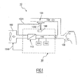
- Figure 1 shows a diagrammatic representation of a known apparatus 10.
- the apparatus 10 comprises a source 100 of pressurised respiratory gas connected to a first end of an inhalation duct 110, whose second end is in contact with a patient to supply him/her with gas from the source 100 during the inhalation phases.
- This second end is shown here by a breathing mask 120. It can also be envisaged to use a apparatus of this type in "invasive" mode, the patient then is intubated with this second end of the duct.
- the mask may have vents for leaks from the breathing mask.
- the apparatus 10 also comprises an expiratory duct 130, whose first end is open to free air to evacuate the gases exhaled by the patient, and whose second end is connected to the patient, joining the second end of the inhalation duct.
- Valves are fitted in order to close the respective ducts 110 and 130 selectively.
- a valve 113 is thus placed on the duct 110, and a valve 133 on the duct 130.
- the valve 113 that is positioned on the inhalation duct is the type of valve whose means for allowing the gas to pass comprise at least one part permitting proportional operation.
- the valve 133 that is positioned on the expiratory duct is a different type of valve.
- This valve comprises an inflatable bladder type sealing element capable of blocking the duct on which the valve is positioned and is pneumatically controlled.
- the valve 113 is controlled by a dedicated electric motor (not shown).
- the valve 133 is pneumatically controlled.
- valve 133 can be selectively controlled by two different pressure lines, as this valve is connected to pressure line selection means which control the valve.
- the apparatus 10 also comprises an assembly collectively designated under the reference 50, which corresponds to means for controlling the operation of the apparatus.
- control means 50 are capable of defining a reference operating value for the gas source 100, and transmitting it by means of a connection 1510.
- This reference operating value is for example expressed in a number of revolutions per minute, in the case of the pressure source 100 being a turbine. It may also be a different type of reference value, for example a pressure output reference value from the pressurised gas source.
- the reference value is a real time reference value and is constantly adapted by the control means 50.
- Such an apparatus operates according to an alternating rhythm of:
- the reference value defined by the control means 50 to be transmitted to the pressurised gas source 100 is composed according to a parameter that is representative of the operation of the apparatus. We will come back to this aspect as part of the description of the invention.
- the apparatus may be operated in different operating modes.
- this apparatus can operate in barometric or volumetric mode.
- the apparatus In barometric mode, the apparatus is controlled according to the pressure in the inhalation duct. In this operating mode, the objective is to provide the patient with a desired pressure during each inhalation phase (see FR 2 812 203 page 19).
- the flow rate in the inhalation duct is a value which results from the pressure control.
- volumetric mode the apparatus is controlled according to the flow rate in the inhalation duct.
- the objective is to provide the patient with a desired volume of gas during each inhalation phase (see FR 2 812 203 page 18).
- the apparatus of FR 2 812 203 is controlled as follows to provide the patient with a desired volume of gas.
- the apparatus of FR 2 812 203 comprises an inhalation valve with a rotating element whose rotation is controlled so as to form in the inhalation valve a passageway section having a dimension which corresponds to the volume which is desired for the patient.
- the angular position of the rotating element of the inhalation valve is thus set at a value corresponding to the volume which is to be delivered to the patient.
- this rotating element is brought into an angular position which corresponds to said value.
- the pressure difference between the upstream and downstream parts of the inhalation valve is kept constant through the control of the pressure at the outlet of the gas source of the apparatus.
- the pressure difference between the upstream and the downstream parts of the inhalation valve at a constant level allows to have an inhalation valve which operates in a linear manner, e.g. the dimension of the passageway defined by the aperture of the rotating element shall be proportional to the flow going through the valve.
- valve 133 when a PEP is to be established in the mask 120 (or more generally at the patient, this text considering as equal the configuration with the mask and the invasive configuration, whether we are considering the presentation of the state of the technique or in that of the invention), the valve 133 must not be sealed by an excessive control pressure, but only by a counter pressure suitable for creating a PEP desired at the patient's level.
- valve 133 is connected to selection means (not shown) to select the line 1331 or the line 1332.
- the inhalation valve of such a apparatus permits precise control of the respiratory gas in the inhalation duct - including for managing different operating modes.
- Such a range of flow rates may be desired, to allow pathologies and illnesses of different types to be treated.
- One purpose of the invention is to improve the above-mentioned aspects.
- Another purpose of the invention is to permit among others to manage (setting the reference value, regulation, etc.) accurately the connection flow rate, and the PEP, separately.
- Yet another purpose of the invention is to allow close control of the leaks of the apparatus to be made, even in the case of the end of the apparatus connected to the patient is a mask. Another purpose is to permit new inhalation phases to be triggered automatically based on this control.
- Yet another purpose of the invention is to provide efficient and reliable means for controling the operation of the apparatus in volumetric modes. In particular, it would be advatageaous to finely control small target values of the volume of gas to be delivered to a patient.
- Another purpose of the invention is to allow the benefits of a configuration in which the inhalation valve is capable of operating proportionally to be maximised.
- the invention proposes a breathing assistance apparatus capable of operating in alternating inhalation and expiratory phases and comprising:
- the invention also concerns an operating control process of a apparatus as mentioned above, characterised in that to establish a PEP during the expiratory phases, the closure of the expiratory valve is controlled by a micro-turbine.
- the micro-turbine when the apparatus operates, can operate constantly and the valve can be controlled by the selective connection of a pneumatic control line of the said valve with the micro-turbine.
- the invention also concerns a process for operating an apparatus as mentioned above in a volumetric mode, characterised in that when a volumetric mode is selected the control of the volume delivered to a patient is obtained by the control of the gas source on the basis of a measured pressure parameter on the inhalation duct.
- this source is a centrifugal fan type turbine (which is to say that its output is on the side of the rotating element, for example via a tangential manifold pipe) with an axial air intake (which is to say that its air input is more or less aligned with the spindle of the rotating part of the turbine).
- this gas source has a particularly low inertia, of around 150 gcm 2 ,
- this valve preferably comprises a cock that can be controlled in rotation in a tubular body, so as to permit an 'all or nothing" or a "proportional" operation.
- the invention can be used with the end of its duct 110 corresponding to a mask (non-invasive mode) or an invasive mode (for example insertion of ducts in patient).
- control means comprise:
- This value is a pressure or flow rate value. As we will see, this value is taken from:
- the switch control allows the operation of the pressure source to be regulated based on the pressure measurements (barometric mode) or the flow rate measurements (volumetric mode).
- an adapted reference value (of pressure or flow rate) is as stated provided to the reference value input 1511.
- the apparatus When the switch 152 connects the input 1512 to the output of the pressure sensor 111, the apparatus is set to barometric mode.
- the apparatus is set to volumetric mode.
- the control means 50 thus comprise a direct closed regulation circuit between the sensors 111 and 112, which characterise in real time and continuously the operation of the apparatus, and the pressurised gas source 100.
- This direct closed regulation circuit permits the reference value transmitted to the source 100 to be adjusted in real time.
- this regulation circuit permits the nature (pressure or flow rate) of the parameter from which the operating reference value of the source 100 is defined to be modified within a phase (inhalation or expiratory).
- This combination permits in fact to control the operation of the apparatus with great precision in real time. This advantage extends to the control of wide ranges of flow rates, as mentioned in the introduction of this text.
- This combination also permits the source 100 to be controlled with great precision, in particular in the perspective of the purposes and objectives of the invention previously mentioned in this text.
- This configuration which permits the operating mode to be changed in real time, based on monitoring of the operation of the apparatus and the parameters stored in a memory of the means 50 connected to the control unit, thus also offers very flexible use.
- the apparatus according to the invention can be operated in particular in a volumetric mode.
- the operation of the device is different from the operation of the device disclosed in FR 2 812 203 .
- volumetric modes are operated on the basis of a control of the gas source.
- the gas source is permanently controlled (through connection 1510) as a function of the desired gas flow (or volume) to be delivered to the patient.
- the flow is permanently measured by the flow sensor 112, and exploited by the control means 50 to control the operation of the gas source 100.
- the rotating element of the inhalation valve 113 is controlled at the beginning of each inspiratory cycle so that it takes a certain position.
- the "certain position" mentioned above corresponds to an opening of the inhalation valve which allows a flow value through the valve substantially equal to the value desired for the patient.
- control of the apparatus is then not performed so as to keep a pressure difference between the upstream and downstream parts of the inhalation valve (like it is the case in the apparatus of FR 2 812 203 ).
- control of the gas source is preferably the control of the rotation speed of the rotor of the compressor of the gas source (in the case of a gas source which is a turbine - or compressor, these two terms being understood as equivalent in the present text).
- the configuration presented above allows among others the operation according to different modes (and a change of the respiratory mode in real time within a given respiratory cycle).
- VAPS Volume Assured Pressure Support
- Such a mode uses the barometric mode and can transfer the mode to a volumetric mode in real time - including within a same inhalation or expiratory cycle.
- an inhalation phase comprises:
- the invention significantly facilitates the application of other modes, for example the SIMV (Synchronous Intermittent Mandatory Ventilation) mode.
- SIMV Serial Intermittent Mandatory Ventilation
- micro-turbine does not generate the unwanted side effects (vibrations, operating anomalies, etc.) observed with traditional auxiliary pressure sources such as compressors, on flap of which is controlled by an alternating back and forth movement.
- the micro-turbine 140 can operate continuously, without its operation needing to be regulated.
- the expiratory valve is controlled by selective connection between the control line 1332 of the expiratory valve and the micro-turbine.
- This selective connection is provided by selection means (not shown) associated to the valve 135.
- the end 120 is fitted with a pressure sensor to monitor, during the expiratory phases, the pressure at the patient and to transmit, in real time, this pressure to the control unit 51 for control by the control unit by means of a regulation circuit (not shown) of the compressor 140.
- this valve comprises:
- the said moving element features a recess that can be aligned with the said orifice of the valve body to allow the gas from the gas source to pass through to the inhalation duct, the said recess comprising:
- the recess of the cock may be shaped so that when the said cock moves to move the inhalation valve from its closed position to its open position, the said first part is first of all aligned with the recess, then the said second part is then aligned with the said recess, if this movement continues.
- the command to open the inhalation valve causes firstly a progressive opening (corresponding to a proportional operation of the valve), then an extension of the opening of the valve to an all or nothing mode.
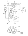
- Figure 3 shows diagrammatically in a developed view an orifice 1130 in the body of the valve and a recess 1131 of a cock.
- the orifice 1130 is rectangular.
- the recess 1131 has a contour formed by a first part 11311 that is more or less triangular, and a second part 11312 that is more or less rectangular.
- a base of the triangle of the first part of the recess is parallel with one side of the rectangle of the second part of the recess.
- This configuration permits both rapid opening of the valve 113 and very good control.
- volumetric modes fine control can be achieved for small desired values of flow, and quick operation can be achieved for higher desired values of flow.
- the cock of the valve is controlled so as to make a small angular move between the closed position of the valve and a target angular position.
- This target angular position shall typically define a passageway for the flow of gas with the "proportional" part 11311 of opening 1131.
- the angular position can possibly define a passageway for the flow of gas with the contribution of the part 11312 of opening 1131.
- the rotation of the cock allows to reach faster an angular position corresponding to the large desired value for the flow.
- the aperture 1311 of the cock shall be designed so that the volumetric modes shall use only the first part 13111 of this aperture.
- the other part 13112 of the aperture shall correspond to angular positions of the cock used for barometric modes.
- the cock can typically be controlled so as to be wide open at the beginning of an inspiratory cycle, and a large passageway through the valve is desired to control the operation of the apparatus on the basis of a pressure parameter.
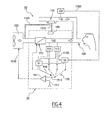
- Figure 4 represents a variant of an embodiment of the invention.
- another flow sensor 132 is positioned on the exhalation duct 130.
- the control means 50 comprise among others comparison and processing means 52 which are connected to the flow sensors 112 (by a connection 1120) and 132 (by a connection 1320).
- These means 52 are capable of monitoring and comparing the respective flow rates in the inhalation 110 and expiratory 130 ducts in real time.
- processing means capable of filtering the difference between the said respective flow rates in real time.
- the said processing means are connected to the control unit 51.
- They include among others a memory and a processor programmed to trigger a new inhalation phase via the control unit 51 when the said filtered difference is higher than a determined threshold.
- these means 52 constantly monitor the change in the difference between the respective flow rates between the inhalation and expiratory ducts (difference corresponding to the difference in flow rate).
- These means 52 are also connected to a memory, and together they can establish during the expiratory phases if the difference in flow rate corresponds:
- the "leak rate” corresponds to a flow rate that is to be established in the inhalation duct, even during the expiratory phases.
- This leak rate corresponds to the flow-by rate.
- Such a leak rate is particularly used and known as part of non-invasive ventilation (which is to say that the end 120 of the inhalation duct is in the form of a mask).
- the leak rate in the case of the invention is carried out by the inhalation valve 113.
- the inhalation valve is not a specific valve as used in the invention (for example in apparatuses where this inhalation valve is a bladder valve similar to the expiratory valve 133), then a leak connection needs to be fitted in parallel to the inhalation valve, to establish a certain pressure in the inhalation circuit 110 even when the inhalation valve is closed.
- inhalation valve capable of proportional operation allows this connection to be dispensed with.
- the leak rate is thus controlled by the controlled opening of the inhalation valve, while the PEP is controlled by the micro-turbine 140 and the expiratory valve.
- This pneumatic control is provided by a pneumatic connection established directly between the pressure source and the expiratory valve (a similar connection to the 1331 connection shown in these figures that controls the expiratory valve).
- the inhalation valve consequently acts like an "all or nothing" valve.
- Temporary excess pressure may result in the inhalation duct, which is a source of discomfort for the patient.
- the speed of rotation of the turbine is then adapted to maintain a PEP of the desired value, by means of a leak connection.
Landscapes
- Health & Medical Sciences (AREA)
- Life Sciences & Earth Sciences (AREA)
- Public Health (AREA)
- Engineering & Computer Science (AREA)
- Anesthesiology (AREA)
- Biomedical Technology (AREA)
- Heart & Thoracic Surgery (AREA)
- Pulmonology (AREA)
- Animal Behavior & Ethology (AREA)
- Hematology (AREA)
- General Health & Medical Sciences (AREA)
- Emergency Medicine (AREA)
- Veterinary Medicine (AREA)
- Respiratory Apparatuses And Protective Means (AREA)
- Measurement Of The Respiration, Hearing Ability, Form, And Blood Characteristics Of Living Organisms (AREA)
- Percussion Or Vibration Massage (AREA)
Applications Claiming Priority (3)
| Application Number | Priority Date | Filing Date | Title |
|---|---|---|---|
| FR0303538A FR2852853B1 (fr) | 2003-03-24 | 2003-03-24 | Dispositif d'aide a la respiration |
| US49592303P | 2003-08-18 | 2003-08-18 | |
| EP04722927.3A EP1610851B1 (de) | 2003-03-24 | 2004-03-24 | Vorrichtung zur atmungsunterstützung |
Related Parent Applications (3)
| Application Number | Title | Priority Date | Filing Date |
|---|---|---|---|
| EP04722927.3 Division | 2004-03-24 | ||
| EP04722927.3A Division-Into EP1610851B1 (de) | 2003-03-24 | 2004-03-24 | Vorrichtung zur atmungsunterstützung |
| EP04722927.3A Division EP1610851B1 (de) | 2003-03-24 | 2004-03-24 | Vorrichtung zur atmungsunterstützung |
Publications (2)
| Publication Number | Publication Date |
|---|---|
| EP2289583A2 true EP2289583A2 (de) | 2011-03-02 |
| EP2289583A3 EP2289583A3 (de) | 2017-12-20 |
Family
ID=32947104
Family Applications (1)
| Application Number | Title | Priority Date | Filing Date |
|---|---|---|---|
| EP10195553.2A Withdrawn EP2289583A3 (de) | 2003-03-24 | 2004-03-24 | Vorrichtung zur Atmungsunterstützung |
Country Status (3)
| Country | Link |
|---|---|
| EP (1) | EP2289583A3 (de) |
| CN (1) | CN100518848C (de) |
| FR (1) | FR2852853B1 (de) |
Cited By (2)
| Publication number | Priority date | Publication date | Assignee | Title |
|---|---|---|---|---|
| US9713690B2 (en) | 2007-08-17 | 2017-07-25 | Resmed Limited | Methods and apparatus for pressure therapy in the treatment of sleep disordered breathing |
| CN110878858A (zh) * | 2019-12-19 | 2020-03-13 | 深圳哈维生物医疗科技有限公司 | 一种气路开关阀及其比例控制方法 |
Families Citing this family (20)
| Publication number | Priority date | Publication date | Assignee | Title |
|---|---|---|---|---|
| US7997272B2 (en) * | 2006-09-11 | 2011-08-16 | Ric Investments, Llc. | Ventilating apparatus and method enabling a patient to talk with or without a trachostomy tube check valve |
| CN110251796B (zh) * | 2008-05-27 | 2022-07-08 | 菲舍尔和佩克尔保健有限公司 | 用于精确湿度控制的增湿器室温度控制 |
| CN102369036B (zh) * | 2009-03-27 | 2015-08-19 | 马奎特紧急护理公司 | 呼吸设备的peep调节 |
| AU2010255402B2 (en) * | 2009-06-03 | 2015-03-26 | Koninklijke Philips Electronics, N.V. | System and method for controlling leakage of a circuit delivering a pressurized flow of breathable gas to a subject |
| CN102107037A (zh) * | 2009-12-28 | 2011-06-29 | 周常安 | 气体递送系统 |
| CN102114290B (zh) * | 2009-12-31 | 2014-08-06 | 北京谊安医疗系统股份有限公司 | 呼吸机的检测方法、设备及系统 |
| EP2371410B1 (de) * | 2010-03-29 | 2016-10-12 | General Electric Company | Anordnung und Verfahren zur Beatmung der Lungen |
| CN102397608B (zh) * | 2010-09-07 | 2014-06-11 | 北京航天长峰股份有限公司 | 吸气阀和呼气阀协同控制的麻醉机、呼吸机压力控制方法 |
| CN103061828B (zh) * | 2011-10-18 | 2015-06-17 | 北京谊安医疗系统股份有限公司 | 涡轮控制方法、装置和系统以及麻醉机和呼吸机 |
| CN103974736B (zh) * | 2011-11-07 | 2017-03-01 | 皇家飞利浦有限公司 | 用于无创通气的自动患者同步调整 |
| CN104203321B (zh) * | 2012-03-21 | 2017-07-18 | 皇家飞利浦有限公司 | 在吹排气系统中产生双向气流 |
| FR3008883B1 (fr) * | 2013-07-23 | 2015-07-17 | Anesteo | Station d'anesthesie pour animaux de laboratoire et procede de determination du taux de saturation en halogenes des filtres d'une telle station d'anesthesie |
| CN103566444B (zh) * | 2013-11-12 | 2015-04-15 | 江苏大学 | 一种医用盐雾测控仪及盐雾浓度定量控制方法 |
| CN105764558B (zh) * | 2013-11-20 | 2019-04-16 | 川苏尼特有限公司 | 一种涡轮呼吸机系统和方法 |
| CN104750129B (zh) * | 2013-12-26 | 2019-08-06 | 北京谊安医疗系统股份有限公司 | 呼吸机的通气流量的控制系统和控制方法 |
| CN111182945B (zh) * | 2017-08-04 | 2022-05-06 | 皇家飞利浦有限公司 | 一种面罩和控制方法 |
| CN108498967A (zh) * | 2018-02-26 | 2018-09-07 | 南昌大学 | 一种个人使用的水柱测压面罩型持续正压pm2.5过滤器 |
| CN109395270A (zh) * | 2018-10-31 | 2019-03-01 | 航宇救生装备有限公司 | 氧气系统压力损失补偿方法 |
| DE102019129549A1 (de) * | 2019-10-31 | 2021-05-06 | Hamilton Medical Ag | Verfahren zur Durchführung eines automatisiert eine Lungenüberdehnung vermeidenden P/V-Manövers und zur Ausführung des Verfahrens ausgebildete Beatmungsvorrichtung |
| DE102020123654A1 (de) | 2020-09-10 | 2022-03-10 | Drägerwerk AG & Co. KGaA | Pneumatikmodul sowie Verfahren zur Versorgung eines Verbrauchers mit einem druckstoßfreien Strom medizinischen Gases oder medizinischer Luft |
Citations (1)
| Publication number | Priority date | Publication date | Assignee | Title |
|---|---|---|---|---|
| FR2812203A1 (fr) | 2000-07-31 | 2002-02-01 | Saime Sarl | Appareil d'aide a la ventilation d'un patient |
Family Cites Families (10)
| Publication number | Priority date | Publication date | Assignee | Title |
|---|---|---|---|---|
| FR1467984A (fr) * | 1965-12-24 | 1967-02-03 | Appareil de premier secours de respiration artificielle | |
| US3741208A (en) * | 1971-02-23 | 1973-06-26 | B Jonsson | Lung ventilator |
| US4527557A (en) * | 1984-11-01 | 1985-07-09 | Bear Medical Systems, Inc. | Medical ventilator system |
| CN1024114C (zh) * | 1989-02-24 | 1994-04-06 | 航天工业部第二研究院第四总体设计部 | 呼吸机的微机控制器 |
| DE3906202A1 (de) * | 1989-02-28 | 1990-09-06 | Medicommerz Gmbh | Verfahren und vorrichtung zur zufuehrung von atemgas |
| SE9602199D0 (sv) * | 1996-06-03 | 1996-06-03 | Siemens Ag | Ventilator |
| FR2755017B1 (fr) * | 1996-10-30 | 1998-12-18 | Taema | Dispositif d'assistance respiratoire |
| SE9703290D0 (sv) * | 1997-09-11 | 1997-09-11 | Siemens Elema Ab | Ventilator |
| SE9801428D0 (sv) * | 1998-04-23 | 1998-04-23 | Siemens Elema Ab | Narkosapparat samt ett förfarande vid narkosapparaten |
| SE9802827D0 (sv) * | 1998-08-25 | 1998-08-25 | Siemens Elema Ab | Ventilator |
-
2003
- 2003-03-24 FR FR0303538A patent/FR2852853B1/fr not_active Expired - Fee Related
-
2004
- 2004-03-24 CN CNB2004800077972A patent/CN100518848C/zh not_active Expired - Fee Related
- 2004-03-24 EP EP10195553.2A patent/EP2289583A3/de not_active Withdrawn
Patent Citations (1)
| Publication number | Priority date | Publication date | Assignee | Title |
|---|---|---|---|---|
| FR2812203A1 (fr) | 2000-07-31 | 2002-02-01 | Saime Sarl | Appareil d'aide a la ventilation d'un patient |
Cited By (2)
| Publication number | Priority date | Publication date | Assignee | Title |
|---|---|---|---|---|
| US9713690B2 (en) | 2007-08-17 | 2017-07-25 | Resmed Limited | Methods and apparatus for pressure therapy in the treatment of sleep disordered breathing |
| CN110878858A (zh) * | 2019-12-19 | 2020-03-13 | 深圳哈维生物医疗科技有限公司 | 一种气路开关阀及其比例控制方法 |
Also Published As
| Publication number | Publication date |
|---|---|
| FR2852853A1 (fr) | 2004-10-01 |
| CN100518848C (zh) | 2009-07-29 |
| CN1764486A (zh) | 2006-04-26 |
| FR2852853B1 (fr) | 2006-12-29 |
| EP2289583A3 (de) | 2017-12-20 |
Similar Documents
| Publication | Publication Date | Title |
|---|---|---|
| EP1610851B1 (de) | Vorrichtung zur atmungsunterstützung | |
| EP2289583A2 (de) | Vorrichtung zur Atmungsunterstützung | |
| US20220265943A1 (en) | Portable light-weight ventilator system | |
| US11717637B2 (en) | Breathable gas inlet control device for respiratory treatment apparatus | |
| US5931163A (en) | Valve for setting the flow of a flow medium | |
| EP0700690B1 (de) | Gerät zum Steuern eines Ausatmungskreislaufs eines Beatmungsgeräts | |
| JP4316138B2 (ja) | ピストン換気装置酸素混合 | |
| US6443154B1 (en) | Apparatus for the supply of a breathing gas | |
| JP3566970B2 (ja) | 送風装置を基本とする換気装置への酸素混合 | |
| US5813399A (en) | System and method for closed loop airway pressure control during the inspiratory cycle of a breath in a patient ventilator using the exhalation valve as a microcomputer-controlled relief valve | |
| US8800557B2 (en) | System and process for supplying respiratory gas under pressure or volumetrically | |
| EP3682930B1 (de) | Ventilator zur gaszufuhrsteuerung | |
| CN110464950B (zh) | 一种高频呼吸机系统及通气控制方法 | |
| JP3615238B2 (ja) | 患者用人工呼吸器の呼吸回路の気道圧力を呼吸の吸息サイクル中に制御するシステム | |
| WO2021224894A1 (en) | Ventilator and method of ventilation | |
| CN116392682A (zh) | 用于将患者侧联结单元与气体混合物的源或汇连接的组件和方法 | |
| BR112018067607B1 (pt) | Bloco de manifold e sistema de ventilador de pressão positiva portátil |
Legal Events
| Date | Code | Title | Description |
|---|---|---|---|
| PUAI | Public reference made under article 153(3) epc to a published international application that has entered the european phase |
Free format text: ORIGINAL CODE: 0009012 |
|
| 17P | Request for examination filed |
Effective date: 20101217 |
|
| AC | Divisional application: reference to earlier application |
Ref document number: 1610851 Country of ref document: EP Kind code of ref document: P |
|
| AK | Designated contracting states |
Kind code of ref document: A2 Designated state(s): DE ES GB SE |
|
| RAP1 | Party data changed (applicant data changed or rights of an application transferred) |
Owner name: RESMED PARIS SAS |
|
| PUAL | Search report despatched |
Free format text: ORIGINAL CODE: 0009013 |
|
| AK | Designated contracting states |
Kind code of ref document: A3 Designated state(s): DE ES GB SE |
|
| RIC1 | Information provided on ipc code assigned before grant |
Ipc: A61M 16/20 20060101ALI20171114BHEP Ipc: A62B 9/00 20060101ALN20171114BHEP Ipc: A61M 16/00 20060101AFI20171114BHEP |
|
| 17Q | First examination report despatched |
Effective date: 20190118 |
|
| STAA | Information on the status of an ep patent application or granted ep patent |
Free format text: STATUS: THE APPLICATION IS DEEMED TO BE WITHDRAWN |
|
| 18D | Application deemed to be withdrawn |
Effective date: 20190301 |