EP2288896B1 - Improvements in staining instruments and methods - Google Patents
Improvements in staining instruments and methods Download PDFInfo
- Publication number
- EP2288896B1 EP2288896B1 EP09765258.0A EP09765258A EP2288896B1 EP 2288896 B1 EP2288896 B1 EP 2288896B1 EP 09765258 A EP09765258 A EP 09765258A EP 2288896 B1 EP2288896 B1 EP 2288896B1
- Authority
- EP
- European Patent Office
- Prior art keywords
- fluid
- slide
- reagent
- slides
- batch
- Prior art date
- Legal status (The legal status is an assumption and is not a legal conclusion. Google has not performed a legal analysis and makes no representation as to the accuracy of the status listed.)
- Active
Links
- 238000010186 staining Methods 0.000 title claims description 45
- 238000000034 method Methods 0.000 title claims description 13
- 239000012530 fluid Substances 0.000 claims description 125
- 239000003153 chemical reaction reagent Substances 0.000 claims description 73
- 230000000712 assembly Effects 0.000 claims description 13
- 238000000429 assembly Methods 0.000 claims description 13
- 210000001519 tissue Anatomy 0.000 description 14
- 239000000523 sample Substances 0.000 description 11
- LFQSCWFLJHTTHZ-UHFFFAOYSA-N Ethanol Chemical compound CCO LFQSCWFLJHTTHZ-UHFFFAOYSA-N 0.000 description 7
- 238000012545 processing Methods 0.000 description 4
- 238000005406 washing Methods 0.000 description 4
- 238000006243 chemical reaction Methods 0.000 description 3
- 238000001514 detection method Methods 0.000 description 3
- 108090000623 proteins and genes Proteins 0.000 description 3
- 239000000758 substrate Substances 0.000 description 3
- 239000002699 waste material Substances 0.000 description 3
- 239000012472 biological sample Substances 0.000 description 2
- 239000000872 buffer Substances 0.000 description 2
- 210000003855 cell nucleus Anatomy 0.000 description 2
- 238000003745 diagnosis Methods 0.000 description 2
- 238000010438 heat treatment Methods 0.000 description 2
- 230000003287 optical effect Effects 0.000 description 2
- 238000002360 preparation method Methods 0.000 description 2
- 102000004169 proteins and genes Human genes 0.000 description 2
- 238000011160 research Methods 0.000 description 2
- 239000000243 solution Substances 0.000 description 2
- 238000012360 testing method Methods 0.000 description 2
- WZUVPPKBWHMQCE-XJKSGUPXSA-N (+)-haematoxylin Chemical compound C12=CC(O)=C(O)C=C2C[C@]2(O)[C@H]1C1=CC=C(O)C(O)=C1OC2 WZUVPPKBWHMQCE-XJKSGUPXSA-N 0.000 description 1
- 239000003298 DNA probe Substances 0.000 description 1
- WZUVPPKBWHMQCE-UHFFFAOYSA-N Haematoxylin Natural products C12=CC(O)=C(O)C=C2CC2(O)C1C1=CC=C(O)C(O)=C1OC2 WZUVPPKBWHMQCE-UHFFFAOYSA-N 0.000 description 1
- 239000003391 RNA probe Substances 0.000 description 1
- 150000001298 alcohols Chemical class 0.000 description 1
- 238000001574 biopsy Methods 0.000 description 1
- 239000007853 buffer solution Substances 0.000 description 1
- 210000002421 cell wall Anatomy 0.000 description 1
- 239000003795 chemical substances by application Substances 0.000 description 1
- 230000001268 conjugating effect Effects 0.000 description 1
- 238000012864 cross contamination Methods 0.000 description 1
- 230000003247 decreasing effect Effects 0.000 description 1
- 239000008367 deionised water Substances 0.000 description 1
- 201000010099 disease Diseases 0.000 description 1
- 208000037265 diseases, disorders, signs and symptoms Diseases 0.000 description 1
- 239000012153 distilled water Substances 0.000 description 1
- YQGOJNYOYNNSMM-UHFFFAOYSA-N eosin Chemical compound [Na+].OC(=O)C1=CC=CC=C1C1=C2C=C(Br)C(=O)C(Br)=C2OC2=C(Br)C(O)=C(Br)C=C21 YQGOJNYOYNNSMM-UHFFFAOYSA-N 0.000 description 1
- 239000000834 fixative Substances 0.000 description 1
- 239000011521 glass Substances 0.000 description 1
- 238000011534 incubation Methods 0.000 description 1
- 238000011835 investigation Methods 0.000 description 1
- 238000002493 microarray Methods 0.000 description 1
- 238000010208 microarray analysis Methods 0.000 description 1
- 239000012120 mounting media Substances 0.000 description 1
- 230000000717 retained effect Effects 0.000 description 1
- -1 stains Substances 0.000 description 1
- XLYOFNOQVPJJNP-UHFFFAOYSA-N water Chemical compound O XLYOFNOQVPJJNP-UHFFFAOYSA-N 0.000 description 1
Images


Classifications
-
- G—PHYSICS
- G01—MEASURING; TESTING
- G01N—INVESTIGATING OR ANALYSING MATERIALS BY DETERMINING THEIR CHEMICAL OR PHYSICAL PROPERTIES
- G01N1/00—Sampling; Preparing specimens for investigation
- G01N1/28—Preparing specimens for investigation including physical details of (bio-)chemical methods covered elsewhere, e.g. G01N33/50, C12Q
- G01N1/30—Staining; Impregnating ; Fixation; Dehydration; Multistep processes for preparing samples of tissue, cell or nucleic acid material and the like for analysis
- G01N1/31—Apparatus therefor
- G01N1/312—Apparatus therefor for samples mounted on planar substrates
Definitions
- the present invention relates to improved apparatus and methods for staining tissue mounted on microscope slides.
- a number of techniques have been developed that involve placing a biological sample onto a substrate. Examples of these techniques include placing tissue samples from biopsies onto microscope slides, and micro-array analysis of samples. In histology, biological samples are attached to a microscope slide and stained to enhance the visibility of features of the tissue. Examples include routine staining, using haematoxylin and eosin stains to improve visibility of cell walls and the cell nucleus. In advanced staining, antibodies are applied to the tissue and then stained to identify the presence or absence of particular proteins, which may be indicative of disease. Other reagents may be applied to tissue such as RNA/DNA probes, which, during a sequence of reactions on the tissue, may bind to DNA in the cell nucleus. The hybridised DNA may then be stained to identify presence or absence of DNA of interest.
- One instrument that is used to test slides is the Bond-max automated advanced staining instrument sold by Leica Microsystems, and described in application number WO 04/001390A1 : BIOLOGICAL REACTION APPARATUS WITH DRAINING MECHANISM.
- a robotic arm is used to dispense reagent onto the slides located onto the instrument.
- the slides are loaded into the instrument in batches, which provides flexibility, as the instrument can start processing a first batch before a second batch is loaded.
- the capacity of the instrument, and its ability to process multiple batches simultaneously, is limited by the number of batches, the protocols and processing time of each slide, and the speed of the robotic arm in completing its tasks.
- WO01/51909 discloses an apparatus for specimen slide preparation. It has autostainer hardware, used for staining tissue specimens that are placed onto glass slides. In particular it uses several different slide racks wherein each slide rack holds one or more slides. In one embodiment, there are six slide racks and each slide rack is capable of holding four slides such that the autostainer can prepare twenty-four different slides simultaneously.
- a first output device is a bulk fluid dispensing tube.
- the bulk fluid dispensing tube is used to deliver relatively large quantities of fluid to slides.
- the bulk fluid dispensing tube may dispense buffer solution from buffer supply or reagents from internal bulk reagent supplies. Particular fluid dispensed is selected by an 8-way distribution valve.
- a second output device is a reagent-dispensing probe. The reagent-dispensing probe draws in specific reagents using syringe pump and then dispenses drawn-in reagents onto specific slides.
- WO03/104801 concerns an apparatus for the automated preparation of treated monolayers of sample material, comprising a centrifuge having a rotor carrying removable chamber blocks.
- a centrifugal cytology system having two types of dispensing systems, batch and random access.
- the batch dispensing system dispenses to chamber blocks of chamber block assemblies common solutions, such as: fixatives, wash solutions, alcohols, stains, mounting media, etc.
- Individual dispensers are used for treating agents that are to be used for one or more, but conventionally not all of the chamber block assemblies arrayed at the circumference of the rotor.
- the present invention is defined by the features of claim 1 and provides an instrument for applying reagents to a group of microscope slides having:
- the slides are grouped into a plurality of batches.
- the group fluid dispenser is mounted on a robotic arm to dispense reagent to all the slides.
- each slide staining assembly is located adjacent to a respective batch fluid dispenser.
- each batch fluid dispenser includes a rail along the side of the slide respective staining assembly, and a dispense head adapted to move along the rail so that fluid is able to be dispensed on each of the slides in the assembly.
- a method of dispensing reagent onto a group of slides utilizing the instrument according to the invention, wherein the group of slides consists of two or more batches of slides, the method comprising the steps of:
- the apparatus 10 shares many common elements and operational methods with the Bond- max instrument sold by the applicant, and in part described in international patent application No. WO 04/001390A1 , titled BIOLOGICAL REACTION APPARATUS WITH DRAINING MECHANISM.
- the Bond-max user manual also describes the operation of the Bond-max instrument. If there is a conflict between the aforementioned documents, the user manual should be read as the correct description.
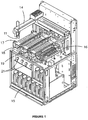
- the apparatus 10 shown in figure 1 is a slide-staining instrument used to stain tissue mounted to microscope slides, but may also be used to apply fluids to substrates, such as micro array plates or other substrates used for biological testing.
- the apparatus 10 includes a group fluid dispenser 11 mounted to a robot arm 14, a first set of reagents, in containers 15, a second set of reagents 16, and slide staining assemblies 17, 18 and 19. Also shown are syringe pumps 21, in fluid connection with reagent containers 15.
- the apparatus 10 is operated by a computer (not shown) used to instruct the apparatus of the protocols to be applied to each slide.
- a computer internal to the apparatus 10 receives information on the protocols to be applied to the slides, and controls the various functions of the apparatus 10, including operation of the robotic arm 14, slide staining assembly 17, 18 and 19, and reagent dispensation.
- the apparatus 10 operates in the same way, and uses the same or similar components, to a Bond-max instrument as sold by the applicant. Where a feature of a fully functioning instrument is not described in the present application, it can be taken that the feature would operate as per a standard Bond-max instrument sold by the applicant and described in the documents cited herein.
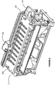
- Each slide staining assembly 17, 18 and 19 has a corresponding batch fluid dispenser 30, as shown in figures 2 and 3 .
- the slide staining assembly 17 (which in this embodiment is identical to the other slide staining assemblies 18 and 19) is shown, having ten slide supports 32 under a cover 33.
- a batch of slides is loaded into one of the slide staining assemblies 17, 18 and 19 on a Bond slide tray 41.
- the slides in the tray 41 are located to correspond with the location of the slide supports 32, and therefore in operation, a slide may be located on each slide support 32.
- Each slide support 32 includes a heater element, for heating the slide and tissue, and has a locating mechanism for moving a covertile on each slide in the same way as Bond-max instruments operating at the time of filing this application.
- the slide staining assembly 17 is located adjacent to a batch fluid dispenser 30 as shown in figures 2 and 3 .
- the batch fluid dispenser 30 includes a rail 34 along the side of the slide staining assembly 17, and a dispense head 36 ( figure 4 ) adapted to move along the rail 34 so that fluid is able to be dispensed on each of the slides in the assembly 17.
- An energy chain device is used to drive the dispense head 36 along the length of the rail 34 to the slide required.
- the dispense head 36 is moved along the rail 34 from one end to the other, stopping at a position adjacent each slide, and dispensing reagent onto the slide to interact with the tissue mounted thereon.
- the energy chain houses a flexible fluid conduit, which terminates in the dispense head 36, to direct fluid onto the slide.
- the conduit is attached to a syringe pump 21 dedicated to the specific dispenser.
- each of the three batch fluid dispensers 30 has its own syringe pump 21.
- Fluid may be drawn from a number of reagent containers 15.
- each of the aforementioned reagent containers 15 has its own manifold.
- Each manifold is connected to all the syringe pumps 21 via individual conduits.
- Each syringe pump 21 has a selectable valve structure that allows the syringe pump 21 to fluidly connect to the desired manifold, and thus access the desired fluid type.
- valve would move to open the connection to the conduit from the alcohol reagent container, and the syringe pump 21 would draw alcohol through the conduit into the syringe until the desired volume was attained.
- the syringe pump 21 then closes the valve to the alcohol container, and opens the connection to the batch fluid dispenser 30.
- the syringe pump 21 then pushes the desired volume of fluid along the conduit to the batch fluid dispenser 30, where alcohol is dispensed onto the appropriate slide 32.
- the amount of fluid drawn into the syringe pump 21 is determined by the volume of fluid in the conduit, as well as the number of slides requiring fluid and the volume of dispense per slide.
- the batch fluid dispenser 30 can therefore dispense a reagent onto one or more slides, by stopping adjacent each slide location. Once the fluid has been dispensed onto the slides, the syringe pump 21 will be empty, but fluid will be retained in the conduit. In order to flush the conduit fluid, the batch fluid dispenser 30 moves to the end of the slide staining assembly 17, 18, 19, where a washing station (not shown) is located. The washing station has an aperture to receive fluid from the batch fluid dispenser 30, whereupon the fluid received by the washing station is directed to a waste container.
- the syringe pump 21 will push a volume of the next fluid to be dispensed through the conduit and to waste to wash out the previous fluid.
- the batch fluid dispenser 30 may move to the slides again and dispense reagent as required.
- some of the fluids are incompatible, for example, they may not be miscible. In such a situation where it is determined that the new fluid may not satisfactorily wash out the old fluid from the conduit, an intermediary fluid may be used.
- incompatible fluids would be distilled water and Dewax fluid. However, alcohol is miscible in both and therefore would be used as an intermediary fluid to remove one fluid before application of a new fluid.
- each slide will have a protocol assigned to it, based on the type of reagent (antibody or probe) to be applied to the tissue sample on the slide.
- a typical protocol has an initial fluid dispense for each slide, application of further fluid, for example a Dewax fluid for removing wax from a sample, application of Epitope retrieval fluid, application of specific reagent for that sample, various detection fluids (stains), all or some of which may be interspersed with the application of wash fluid to remove the previous fluid.
- fluids may in some cases need to be done at specific intervals, for example antibodies may need to be left on a sample for a specific amount of time, before being washed off. Staining of tissue can be affected if fluid is left on for too long, or if fluid levels are not replenished causing tissue to dry out. There are also times when no fluid should be dispensed onto a slide, for example incubation time, and therefore the robotic arm and dispenser may remain idle for a period of time before the next operation is required. Thus timing of the dispensation of fluid can be critical, which can cause scheduling issues when running two or more batches simultaneously.
- the apparatus 10 deals with each tray of slides as batches, and can begin operations on a newly entered batch before completing operations on a previously loaded batch.
- the Bond-max instrument as in the apparatus 10, there are three slide staining assemblies 17, 18 and 19 that represent three batches when loaded, however in the Bond-max instrument there is only one dispenser capable of dispensing fluid onto all slides in the slide staining assemblies.
- the Bond-max instrument one robot must undertake all fluid dispensing tasks on all batches of slides.
- the operation of the group fluid dispenser 11 has been reduced by the use of specific batch fluid dispensers 30 plumbed into reagent containers 15.
- the fluid dispenser 11 on robotic arm 14 moves along the line of slides in a batch within a slide staining assembly 17, 18, 19 and undertakes the required dispensation of fluid on all slides in the batch before moving to another slide assembly 17, 18, 19.
- reagent containers 16 may contain reagents such as detection reagents (conjugating reagents and stains), antibodies and probes. Given their small volumes and high value, these containers are not plumbed into any dispenser, as the fluid lines and washing would waste too much reagent. Instead, the group fluid dispenser 11 has a pipette used to withdraw reagent directly out of the required reagent container 16. In the apparatus 10 shown, over thirty different reagent containers 16 may be loaded into the apparatus 10, and these typically include one detection system consisting of nine reagents, with the remainder being various antibodies or probes. It is therefore possible to apply a different antibody to most slides. In operation, it is necessary to rinse out the group fluid dispenser 11 between dispensations of different antibodies, to prevent cross contamination.
- detection reagents conjugating reagents and stains
- antibodies and probes antibodies and probes
- the robot arm 14 may need to move from one of the reagent containers 16 to draw fluid, then to a slide to dispense fluid, then to a wash station to wash the dispenser pipette, then to another reagent container 16, then to a new slide.
- the robot arm may be in use for a considerable period of time to dispense fluid onto ten slides in a single batch. During this period, dispensation of other fluids onto other batches cannot take place from the robot arm 14 and dispenser 11, as the group fluid dispenser is fully utilised.
- batch fluid dispensers 30 as shown in figure 2 are used to dispense reagents from reagent containers 15 onto the slides.
- group fluid dispenser 11 is dispensing antibodies onto the slides in slide staining assembly 17
- one of the batch fluid dispensers 30 may dispense reagent onto the slides in another batch, or slide staining assembly 18 and/or 19.
- the group fluid dispenser 11 can dispense reagent onto each slide in a batch, while the dispensers 30 associated with each slide staining assembly 17, 18 and 19 can move from side to side in their own batch and dispense reagent. This may be done simultaneously as required, thus freeing the group fluid dispenser 11 and robot arm, and allowing the batches to be completed more quickly.
- the group fluid dispenser 11 now has fewer dispenses to make, providing greater free time between dispenses.
- Typical reagents that the batch fluid dispenser 30 would dispense include reagents such as deionised water, alcohol, buffer fluid, Epitope retrieval fluid, and Dewax fluid. These fluids may be called bulk fluids, as they typically are stored in reagent containers 15 of between 2000-5000ml. In contrast, the reagent containers 16 typically hold between 5-30ml.
- the batch fluid dispensers 30 use an optical sensor to detect when they are in the correct position.
- the batch fluid dispenser 30 is moved by a stepper motor, which is controlled to step a predetermined number of steps from one dispense position to the next. Once the motor has driven the batch fluid dispenser 30 the assigned number of steps, the system checks the optical sensor to determine whether the batch fluid dispenser 30 is in the correct position relative to the slide. If the batch fluid dispenser 30 is not in the correct position, the system moves the batch fluid dispenser 30 forward along the track 34 until it detects that it is in the correct position. While moving along track 34, the batch fluid dispenser 30 is supported in the track 34 by guide wheels 42.
- the apparatus 10 may operate with one, two or three slide trays loaded into the three staining assemblies.
- Other examples of apparatus may not be limited to three slide staining assemblies, and for example may have two, or more depending on the throughput and size of apparatus required.
Description
- The present invention relates to improved apparatus and methods for staining tissue mounted on microscope slides.
- A number of techniques have been developed that involve placing a biological sample onto a substrate. Examples of these techniques include placing tissue samples from biopsies onto microscope slides, and micro-array analysis of samples. In histology, biological samples are attached to a microscope slide and stained to enhance the visibility of features of the tissue. Examples include routine staining, using haematoxylin and eosin stains to improve visibility of cell walls and the cell nucleus. In advanced staining, antibodies are applied to the tissue and then stained to identify the presence or absence of particular proteins, which may be indicative of disease. Other reagents may be applied to tissue such as RNA/DNA probes, which, during a sequence of reactions on the tissue, may bind to DNA in the cell nucleus. The hybridised DNA may then be stained to identify presence or absence of DNA of interest.
- The number of proteins that may be used in investigation, research or diagnosis is large, and ever increasing. Similarly, the number of genes of interest is also increasing. If an automated instrument is to apply the wide range of reagents used in diagnosis or research, then the instrument must have flexibility. However, it is also important that samples are completed quickly and efficiently.
- One instrument that is used to test slides is the Bond-max automated advanced staining instrument sold by Leica Microsystems, and described in application number
WO 04/001390A1 -
WO01/51909 -
WO03/104801 - The present invention is defined by the features of claim 1 and provides an instrument for applying reagents to a group of microscope slides having:
- a plurality of slide supports;
- a first set of one or more reagent containers;
- a second set of one or more reagent containers;
- a group fluid dispenser, for dispensing fluid drawn from one or more reagent containers of the first set of reagent containers;
- wherein the instrument is characterized in that it comprises a plurality of slide staining assemblies into each of which a batch of slides can be located, each slide staining assembly having a batch fluid dispenser for dispensing fluid drawn from one or more reagent containers of the second set of reagent containers,
- and wherein the instrument is configured such that the group dispenser can dispense reagent onto each slide in a batch while simultaneously the batch fluid dispensers associated with each slide staining assembly dispense reagent.
- According to an embodiment, the slides are grouped into a plurality of batches.
- According to an embodiment, the group fluid dispenser is mounted on a robotic arm to dispense reagent to all the slides.
- According to an embodiment, each slide staining assembly is located adjacent to a respective batch fluid dispenser.
- According to an embodiment, each batch fluid dispenser includes a rail along the side of the slide respective staining assembly, and a dispense head adapted to move along the rail so that fluid is able to be dispensed on each of the slides in the assembly.
- Further, there is provided a method of dispensing reagent onto a group of slides, utilizing the instrument according to the invention, wherein the group of slides consists of two or more batches of slides,
the method comprising the steps of: - loading the batches of slides into the slide staining assemblies;
- wherein the group dispenser dispenses reagent onto each slide in a batch while simultaneously the batch fluid dispensers of each slide staining assembly dispense reagent.
-
-
Figure 1 is a schematic drawing of an apparatus having multiple fluid dispensers; -
Figure 2 is a schematic drawing of a portion of the apparatus offigure 1 showing a slide staining assembly and a fluid dispenser; -
Figure 3 is a schematic drawing of a fluid dispenser and slide staining assembly of the apparatus offigure 1 ; -
Figure 4 is a schematic drawing of a cross section of a fluid dispenser head of the fluid dispenser shown infigures 2 and3 . - The apparatus 10 shares many common elements and operational methods with the Bond- max instrument sold by the applicant, and in part described in international patent application No.
WO 04/001390A1 - The apparatus 10 shown in
figure 1 is a slide-staining instrument used to stain tissue mounted to microscope slides, but may also be used to apply fluids to substrates, such as micro array plates or other substrates used for biological testing. The apparatus 10 includes agroup fluid dispenser 11 mounted to arobot arm 14, a first set of reagents, incontainers 15, a second set ofreagents 16, andslide staining assemblies syringe pumps 21, in fluid connection withreagent containers 15. - The apparatus 10 is operated by a computer (not shown) used to instruct the apparatus of the protocols to be applied to each slide. A computer internal to the apparatus 10 receives information on the protocols to be applied to the slides, and controls the various functions of the apparatus 10, including operation of the
robotic arm 14,slide staining assembly - Each
slide staining assembly batch fluid dispenser 30, as shown infigures 2 and3 . - In
figure 2 and3 , the slide staining assembly 17 (which in this embodiment is identical to the otherslide staining assemblies 18 and 19) is shown, having ten slide supports 32 under acover 33. In operation a batch of slides is loaded into one of theslide staining assemblies Bond slide tray 41. The slides in thetray 41 are located to correspond with the location of the slide supports 32, and therefore in operation, a slide may be located on eachslide support 32. Eachslide support 32 includes a heater element, for heating the slide and tissue, and has a locating mechanism for moving a covertile on each slide in the same way as Bond-max instruments operating at the time of filing this application. - The
slide staining assembly 17 is located adjacent to abatch fluid dispenser 30 as shown infigures 2 and3 . Thebatch fluid dispenser 30 includes arail 34 along the side of theslide staining assembly 17, and a dispense head 36 (figure 4 ) adapted to move along therail 34 so that fluid is able to be dispensed on each of the slides in theassembly 17. An energy chain device is used to drive the dispensehead 36 along the length of therail 34 to the slide required. In one example, the dispensehead 36 is moved along therail 34 from one end to the other, stopping at a position adjacent each slide, and dispensing reagent onto the slide to interact with the tissue mounted thereon. The energy chain houses a flexible fluid conduit, which terminates in the dispensehead 36, to direct fluid onto the slide. The conduit is attached to asyringe pump 21 dedicated to the specific dispenser. Thus in the instrument shown, each of the threebatch fluid dispensers 30 has itsown syringe pump 21. Fluid may be drawn from a number ofreagent containers 15. In the present example each of theaforementioned reagent containers 15 has its own manifold. Each manifold is connected to all the syringe pumps 21 via individual conduits. Eachsyringe pump 21 has a selectable valve structure that allows thesyringe pump 21 to fluidly connect to the desired manifold, and thus access the desired fluid type. For example, ifdispenser 30 was required to dispense alcohol, the valve would move to open the connection to the conduit from the alcohol reagent container, and thesyringe pump 21 would draw alcohol through the conduit into the syringe until the desired volume was attained. Thesyringe pump 21 then closes the valve to the alcohol container, and opens the connection to thebatch fluid dispenser 30. Thesyringe pump 21 then pushes the desired volume of fluid along the conduit to thebatch fluid dispenser 30, where alcohol is dispensed onto theappropriate slide 32. - The amount of fluid drawn into the
syringe pump 21 is determined by the volume of fluid in the conduit, as well as the number of slides requiring fluid and the volume of dispense per slide. Thebatch fluid dispenser 30 can therefore dispense a reagent onto one or more slides, by stopping adjacent each slide location. Once the fluid has been dispensed onto the slides, thesyringe pump 21 will be empty, but fluid will be retained in the conduit. In order to flush the conduit fluid, thebatch fluid dispenser 30 moves to the end of theslide staining assembly batch fluid dispenser 30, whereupon the fluid received by the washing station is directed to a waste container. Typically, in the present embodiment, thesyringe pump 21 will push a volume of the next fluid to be dispensed through the conduit and to waste to wash out the previous fluid. Once old fluid has been flushed, thebatch fluid dispenser 30 may move to the slides again and dispense reagent as required. - In certain situations, some of the fluids are incompatible, for example, they may not be miscible. In such a situation where it is determined that the new fluid may not satisfactorily wash out the old fluid from the conduit, an intermediary fluid may be used.
- An example of incompatible fluids would be distilled water and Dewax fluid. However, alcohol is miscible in both and therefore would be used as an intermediary fluid to remove one fluid before application of a new fluid.
- In operation of the apparatus 10, having slides each with a tissue sample mounted thereon, each slide will have a protocol assigned to it, based on the type of reagent (antibody or probe) to be applied to the tissue sample on the slide. A typical protocol has an initial fluid dispense for each slide, application of further fluid, for example a Dewax fluid for removing wax from a sample, application of Epitope retrieval fluid, application of specific reagent for that sample, various detection fluids (stains), all or some of which may be interspersed with the application of wash fluid to remove the previous fluid.
- Application of the fluids may in some cases need to be done at specific intervals, for example antibodies may need to be left on a sample for a specific amount of time, before being washed off. Staining of tissue can be affected if fluid is left on for too long, or if fluid levels are not replenished causing tissue to dry out. There are also times when no fluid should be dispensed onto a slide, for example incubation time, and therefore the robotic arm and dispenser may remain idle for a period of time before the next operation is required. Thus timing of the dispensation of fluid can be critical, which can cause scheduling issues when running two or more batches simultaneously.
- It is not necessary to load all three trays at once. It is possible to load a first tray having between one and ten slides, into a
staining assembly slide staining assemblies group fluid dispenser 11 has been reduced by the use of specificbatch fluid dispensers 30 plumbed intoreagent containers 15. - In operation, the
fluid dispenser 11 onrobotic arm 14 moves along the line of slides in a batch within aslide staining assembly slide assembly - In the apparatus 10,
reagent containers 16 may contain reagents such as detection reagents (conjugating reagents and stains), antibodies and probes. Given their small volumes and high value, these containers are not plumbed into any dispenser, as the fluid lines and washing would waste too much reagent. Instead, thegroup fluid dispenser 11 has a pipette used to withdraw reagent directly out of the requiredreagent container 16. In the apparatus 10 shown, over thirtydifferent reagent containers 16 may be loaded into the apparatus 10, and these typically include one detection system consisting of nine reagents, with the remainder being various antibodies or probes. It is therefore possible to apply a different antibody to most slides. In operation, it is necessary to rinse out thegroup fluid dispenser 11 between dispensations of different antibodies, to prevent cross contamination. Therefore therobot arm 14 may need to move from one of thereagent containers 16 to draw fluid, then to a slide to dispense fluid, then to a wash station to wash the dispenser pipette, then to anotherreagent container 16, then to a new slide. Thus the robot arm may be in use for a considerable period of time to dispense fluid onto ten slides in a single batch. During this period, dispensation of other fluids onto other batches cannot take place from therobot arm 14 anddispenser 11, as the group fluid dispenser is fully utilised. In the apparatus 10,batch fluid dispensers 30 as shown infigure 2 are used to dispense reagents fromreagent containers 15 onto the slides. For example, whilegroup fluid dispenser 11 is dispensing antibodies onto the slides inslide staining assembly 17, one of thebatch fluid dispensers 30 may dispense reagent onto the slides in another batch, or slidestaining assembly 18 and/or 19. - Thus in operation, the
group fluid dispenser 11 can dispense reagent onto each slide in a batch, while thedispensers 30 associated with eachslide staining assembly group fluid dispenser 11 and robot arm, and allowing the batches to be completed more quickly. Thegroup fluid dispenser 11 now has fewer dispenses to make, providing greater free time between dispenses. This makes scheduling a new batch much easier as the gap between times the group fluid dispenser (dispenser 11) is in use is larger, and the time required by thegroup fluid dispenser 11 to dispense some reagents may be shorter, as some dispensing may be undertaken by the batch dispensers (dispensers 30) to undertake a dispense on all sides is shorter. Thus, it is much easier to interleave the operations of thegroup fluid dispenser 11 in one batch into the operations of thegroup fluid dispenser 11 in another batch, and subsequently this reduces the time to complete three batches. - Typical reagents that the
batch fluid dispenser 30 would dispense include reagents such as deionised water, alcohol, buffer fluid, Epitope retrieval fluid, and Dewax fluid. These fluids may be called bulk fluids, as they typically are stored inreagent containers 15 of between 2000-5000ml. In contrast, thereagent containers 16 typically hold between 5-30ml. - In the present embodiment, the
batch fluid dispensers 30 use an optical sensor to detect when they are in the correct position. Thebatch fluid dispenser 30 is moved by a stepper motor, which is controlled to step a predetermined number of steps from one dispense position to the next. Once the motor has driven thebatch fluid dispenser 30 the assigned number of steps, the system checks the optical sensor to determine whether thebatch fluid dispenser 30 is in the correct position relative to the slide. If thebatch fluid dispenser 30 is not in the correct position, the system moves thebatch fluid dispenser 30 forward along thetrack 34 until it detects that it is in the correct position. While moving alongtrack 34, thebatch fluid dispenser 30 is supported in thetrack 34 byguide wheels 42. - The apparatus 10 may operate with one, two or three slide trays loaded into the three staining assemblies. Other examples of apparatus may not be limited to three slide staining assemblies, and for example may have two, or more depending on the throughput and size of apparatus required.
Claims (9)
- An instrument for applying reagents to a group of microscope slides having:a plurality of slide supports;a first set of one or more reagent containers (15);a second set of one or more reagent containers (16);a group fluid dispenser (11), for dispensing fluid drawn from one or more reagent containers of the first set of reagent containers;wherein the instrument is characterized in that it comprises a plurality of slide staining assemblies (17, 18, 19) into each of which a batch of slides can be loaded, each slide staining assembly having a batch fluid dispenser (30) for dispensing fluid drawn from one or more reagent containers of the second set of reagent containers,and wherein the instrument is configured such that the group dispenser (11) can dispense reagent onto each slide in a batch while simultaneously the batch fluid dispensers (30) associated with each slide staining assembly (17, 18, 19) dispense reagent.
- The instrument of claim 1 wherein the slides are grouped into a plurality of batches.
- The instrument of claims 1 or 2, wherein the group fluid dispenser (11) is mounted on a robotic arm (14) to dispense reagent to all the slides.
- The instrument according to any of the preceding claims, wherein each slide staining assembly (17) is located adjacent to a respective batch fluid dispenser (30).
- The instrument according to any of the preceding claims, wherein each batch fluid dispenser (30) includes a rail (34) along the side of the slide respective staining assembly (17), and a dispense head (36) adapted to move along the rail (34) so that fluid is able to be dispensed on each of the slides in the assembly (17).
- A method of dispensing reagent onto a group of microscope slides, utilizing the instrument according to any of the preceding claims, wherein the group of slides consists of two or more batches of slides,
the method comprising the steps of:loading the batches of slides into the slide staining assemblies;wherein the group dispenser (11) dispenses reagent onto each slide in a batch while simultaneously the batch fluid dispensers (30) of each slide staining assembly (17, 18, 19) dispense reagent. - Method according to claim 6, wherein the group fluid dispenser (11) has a pipette used to withdraw reagent directly out of a required reagent container (16).
- Method according to claim 7, wherein a robot arm (14) moves the group fluid dispenser (11) from one reagent container (16) to draw fluid, then to a slide to dispense fluid, then to a wash station to wash the dispenser pipette, then to another reagent container (16), then to a new slide.
- Method according to any of claims 6-8, wherein, while group fluid dispenser (11) is dispensing reagent onto slides in a slide staining assembly (17), one of the batch fluid dispensers (30) dispenses reagent onto the slides in another batch, or another slide staining assembly (18 and/or 19).
Applications Claiming Priority (3)
| Application Number | Priority Date | Filing Date | Title |
|---|---|---|---|
| US6176708P | 2008-06-16 | 2008-06-16 | |
| AU2008903057A AU2008903057A0 (en) | 2008-06-16 | Improvements in Staining instruments and methods | |
| PCT/AU2009/000771 WO2009152569A1 (en) | 2008-06-16 | 2009-06-16 | Improvements in staining instruments and methods |
Publications (3)
| Publication Number | Publication Date |
|---|---|
| EP2288896A1 EP2288896A1 (en) | 2011-03-02 |
| EP2288896A4 EP2288896A4 (en) | 2017-11-08 |
| EP2288896B1 true EP2288896B1 (en) | 2019-10-02 |
Family
ID=41433592
Family Applications (1)
| Application Number | Title | Priority Date | Filing Date |
|---|---|---|---|
| EP09765258.0A Active EP2288896B1 (en) | 2008-06-16 | 2009-06-16 | Improvements in staining instruments and methods |
Country Status (6)
| Country | Link |
|---|---|
| US (1) | US8758707B2 (en) |
| EP (1) | EP2288896B1 (en) |
| JP (2) | JP2011524527A (en) |
| CN (1) | CN102159932B (en) |
| AU (1) | AU2009260113B2 (en) |
| WO (1) | WO2009152569A1 (en) |
Families Citing this family (22)
| Publication number | Priority date | Publication date | Assignee | Title |
|---|---|---|---|---|
| EP3450954B1 (en) | 2007-12-10 | 2020-09-02 | Agilent Technologies, Inc. | A tissue processing apparatus |
| US10746752B2 (en) | 2009-11-13 | 2020-08-18 | Ventana Medical Systems, Inc. | Opposables and automated specimen processing systems with opposables |
| CN102116712B (en) * | 2011-01-31 | 2012-07-04 | 浙江世纪康大医疗科技有限公司 | Fully-automatic immune tissue chemical dyeing instrument |
| US8932543B2 (en) * | 2011-09-21 | 2015-01-13 | Sakura Finetek U.S.A., Inc. | Automated staining system and reaction chamber |
| WO2013057050A1 (en) * | 2011-10-17 | 2013-04-25 | Victorious Medical Systems Aps | Method, apparatus and system for staining of biological samples |
| US9381524B2 (en) | 2011-11-08 | 2016-07-05 | Becton, Dickinson And Company | System and method for automated sample preparation |
| JP2014533824A (en) * | 2011-11-16 | 2014-12-15 | ライカ・バイオシステムズ・メルボルン・プロプライエタリー・リミテッドLeica Biosystems Melbourne Pty Ltd | Biological sample processing device |
| EP2780722B1 (en) * | 2011-11-16 | 2020-06-24 | Leica Biosystems Melbourne Pty Ltd | An automated system and method of treating tissue samples on slides |
| CN102768142B (en) * | 2012-07-19 | 2014-09-10 | 广州市达诚医疗技术有限公司 | Dyeing device |
| JP6346191B2 (en) * | 2012-11-01 | 2018-06-20 | ライカ・バイオシステムズ・メルボルン・プロプライエタリー・リミテッドLeica Biosystems Melbourne Pty Ltd | Fluid transportation system |
| JP6117936B2 (en) * | 2012-12-26 | 2017-04-19 | ベンタナ メディカル システムズ, インコーポレイテッド | Sample processing system and method for suppressing evaporation |
| CN103196732B (en) * | 2013-03-29 | 2015-10-14 | 麦克奥迪(厦门)医疗诊断系统有限公司 | A kind of pathology automated DNA coloring system and colouring method |
| KR20150139845A (en) | 2013-04-05 | 2015-12-14 | 가부시키가이샤 니찌레이 바이오사이언스 | Receptacle containing test reagent |
| EP3207379B1 (en) * | 2014-10-19 | 2023-05-24 | Peddinti, Kamal, Prasad | Automated batch stainer for immunohistochemistry |
| WO2016190111A1 (en) * | 2015-05-26 | 2016-12-01 | オリンパス株式会社 | Sample staining device and sample staining method |
| CA3012489C (en) | 2016-02-29 | 2023-01-31 | Ventana Medical Systems, Inc. | System and method for dispense characterization |
| WO2017218882A1 (en) | 2016-06-16 | 2017-12-21 | Nanocytomics, LLC | Automated staining system |
| WO2018044280A1 (en) * | 2016-08-30 | 2018-03-08 | Qdaisat Sadeem Z S | Automated slide dropping system |
| CA3055284A1 (en) * | 2017-03-31 | 2018-10-04 | X-Zell Inc. | Automatic slide staining and cooling systems |
| KR20200055950A (en) * | 2018-11-14 | 2020-05-22 | 주식회사 케이에스 | Microbial automatic dyeing platform system including pretreatment process |
| JP2023544113A (en) | 2020-09-22 | 2023-10-20 | エフ. ホフマン-ラ ロシュ アーゲー | Antibodies specific for α-1,6-core-fucosylated PSA and its fucosylated fragments |
| CN114324851A (en) * | 2021-10-09 | 2022-04-12 | 北京海格莱生物科技有限公司 | Multi-channel slide specimen cleaning device, immunohistochemical specimen processor and method |
Family Cites Families (16)
| Publication number | Priority date | Publication date | Assignee | Title |
|---|---|---|---|---|
| US5180606A (en) * | 1989-05-09 | 1993-01-19 | Wescor, Inc. | Apparatus for applying a controlled amount of reagent to a microscope slide or the like |
| US5595707A (en) * | 1990-03-02 | 1997-01-21 | Ventana Medical Systems, Inc. | Automated biological reaction apparatus |
| DE69117052T2 (en) * | 1990-03-02 | 1996-11-14 | Ventana Med Syst Inc | AUTOMATIC BIOLOGICAL REACTOR |
| DE4006635A1 (en) * | 1990-03-03 | 1991-09-05 | Georg Binnen | TOW NOZZLE DEVICE FOR HIGH SPEED BOW FEEDER |
| US5439649A (en) * | 1993-09-29 | 1995-08-08 | Biogenex Laboratories | Automated staining apparatus |
| JPH09101247A (en) * | 1995-10-05 | 1997-04-15 | Kanagawa Kagaku Gijutsu Akad | Method and apparatus for dyeing thin sample |
| JP2002507738A (en) * | 1998-03-24 | 2002-03-12 | バイオジェネックス ラボラトリーズ | Automatic coloring equipment |
| US6746851B1 (en) | 2000-01-14 | 2004-06-08 | Lab Vision Corporation | Method for automated staining of specimen slides |
| US7135146B2 (en) * | 2000-10-11 | 2006-11-14 | Innovadyne Technologies, Inc. | Universal non-contact dispense peripheral apparatus and method for a primary liquid handling device |
| EP1504260A4 (en) | 2002-04-13 | 2014-04-02 | Newport Instr | Centrifugal cytology system, chamber block and method for the preparation of treated monolayers of sample material |
| US7468161B2 (en) * | 2002-04-15 | 2008-12-23 | Ventana Medical Systems, Inc. | Automated high volume slide processing system |
| DK1494808T3 (en) * | 2002-04-15 | 2013-09-23 | Ventana Med Syst Inc | High capacity automated slide staining system |
| EP2420814B1 (en) * | 2002-04-26 | 2015-08-26 | Ventana Medical Systems, Inc. | Automatic slide processing apparatus |
| JP2005530165A (en) | 2002-06-20 | 2005-10-06 | ビジョン・バイオシステムズ・リミテッド | Biological reaction device with fluid discharge mechanism |
| US7501283B2 (en) * | 2003-08-11 | 2009-03-10 | Sakura Finetek U.S.A., Inc. | Fluid dispensing apparatus |
| US7744817B2 (en) * | 2003-08-11 | 2010-06-29 | Sakura Finetek U.S.A., Inc. | Manifold assembly |
-
2009
- 2009-06-16 US US12/999,259 patent/US8758707B2/en active Active
- 2009-06-16 JP JP2011513821A patent/JP2011524527A/en active Pending
- 2009-06-16 EP EP09765258.0A patent/EP2288896B1/en active Active
- 2009-06-16 AU AU2009260113A patent/AU2009260113B2/en active Active
- 2009-06-16 CN CN200980131802.3A patent/CN102159932B/en active Active
- 2009-06-16 WO PCT/AU2009/000771 patent/WO2009152569A1/en active Application Filing
-
2015
- 2015-01-09 JP JP2015003540A patent/JP5889448B2/en active Active
Non-Patent Citations (1)
| Title |
|---|
| None * |
Also Published As
| Publication number | Publication date |
|---|---|
| US8758707B2 (en) | 2014-06-24 |
| AU2009260113B2 (en) | 2016-03-03 |
| JP5889448B2 (en) | 2016-03-22 |
| JP2015108631A (en) | 2015-06-11 |
| EP2288896A1 (en) | 2011-03-02 |
| WO2009152569A1 (en) | 2009-12-23 |
| JP2011524527A (en) | 2011-09-01 |
| CN102159932B (en) | 2014-09-24 |
| US20110174088A1 (en) | 2011-07-21 |
| AU2009260113A1 (en) | 2009-12-23 |
| EP2288896A4 (en) | 2017-11-08 |
| CN102159932A (en) | 2011-08-17 |
Similar Documents
| Publication | Publication Date | Title |
|---|---|---|
| EP2288896B1 (en) | Improvements in staining instruments and methods | |
| EP2097730B1 (en) | Thin film apparatus and method | |
| AU2003228709B2 (en) | Automated molecular pathology apparatus having fixed slide platforms | |
| EP1494808B1 (en) | Automated high volume slide staining system | |
| EP3324171B1 (en) | Automated high volume slide processing method | |
| US7404927B2 (en) | Automated molecular pathology apparatus having fixed slide platforms | |
| EP3126847B1 (en) | Automated specimen processing systems and multistep processing of microscope slides | |
| HU230739B1 (en) | Apparatus and method for automatic staining masking, digitizing of slides |
Legal Events
| Date | Code | Title | Description |
|---|---|---|---|
| PUAI | Public reference made under article 153(3) epc to a published international application that has entered the european phase |
Free format text: ORIGINAL CODE: 0009012 |
|
| 17P | Request for examination filed |
Effective date: 20101217 |
|
| AK | Designated contracting states |
Kind code of ref document: A1 Designated state(s): AT BE BG CH CY CZ DE DK EE ES FI FR GB GR HR HU IE IS IT LI LT LU LV MC MK MT NL NO PL PT RO SE SI SK TR |
|
| AX | Request for extension of the european patent |
Extension state: AL BA RS |
|
| DAX | Request for extension of the european patent (deleted) | ||
| RA4 | Supplementary search report drawn up and despatched (corrected) |
Effective date: 20171011 |
|
| RIC1 | Information provided on ipc code assigned before grant |
Ipc: G01N 1/31 20060101AFI20171005BHEP Ipc: G01N 35/00 20060101ALI20171005BHEP |
|
| STAA | Information on the status of an ep patent application or granted ep patent |
Free format text: STATUS: EXAMINATION IS IN PROGRESS |
|
| 17Q | First examination report despatched |
Effective date: 20180810 |
|
| GRAP | Despatch of communication of intention to grant a patent |
Free format text: ORIGINAL CODE: EPIDOSNIGR1 |
|
| STAA | Information on the status of an ep patent application or granted ep patent |
Free format text: STATUS: GRANT OF PATENT IS INTENDED |
|
| INTG | Intention to grant announced |
Effective date: 20190409 |
|
| GRAS | Grant fee paid |
Free format text: ORIGINAL CODE: EPIDOSNIGR3 |
|
| GRAA | (expected) grant |
Free format text: ORIGINAL CODE: 0009210 |
|
| STAA | Information on the status of an ep patent application or granted ep patent |
Free format text: STATUS: THE PATENT HAS BEEN GRANTED |
|
| AK | Designated contracting states |
Kind code of ref document: B1 Designated state(s): AT BE BG CH CY CZ DE DK EE ES FI FR GB GR HR HU IE IS IT LI LT LU LV MC MK MT NL NO PL PT RO SE SI SK TR |
|
| REG | Reference to a national code |
Ref country code: GB Ref legal event code: FG4D |
|
| REG | Reference to a national code |
Ref country code: CH Ref legal event code: EP Ref country code: AT Ref legal event code: REF Ref document number: 1186718 Country of ref document: AT Kind code of ref document: T Effective date: 20191015 |
|
| REG | Reference to a national code |
Ref country code: DE Ref legal event code: R096 Ref document number: 602009060011 Country of ref document: DE |
|
| REG | Reference to a national code |
Ref country code: IE Ref legal event code: FG4D |
|
| REG | Reference to a national code |
Ref country code: NL Ref legal event code: MP Effective date: 20191002 |
|
| REG | Reference to a national code |
Ref country code: LT Ref legal event code: MG4D |
|
| REG | Reference to a national code |
Ref country code: AT Ref legal event code: MK05 Ref document number: 1186718 Country of ref document: AT Kind code of ref document: T Effective date: 20191002 |
|
| PG25 | Lapsed in a contracting state [announced via postgrant information from national office to epo] |
Ref country code: GR Free format text: LAPSE BECAUSE OF FAILURE TO SUBMIT A TRANSLATION OF THE DESCRIPTION OR TO PAY THE FEE WITHIN THE PRESCRIBED TIME-LIMIT Effective date: 20200103 Ref country code: NO Free format text: LAPSE BECAUSE OF FAILURE TO SUBMIT A TRANSLATION OF THE DESCRIPTION OR TO PAY THE FEE WITHIN THE PRESCRIBED TIME-LIMIT Effective date: 20200102 Ref country code: PL Free format text: LAPSE BECAUSE OF FAILURE TO SUBMIT A TRANSLATION OF THE DESCRIPTION OR TO PAY THE FEE WITHIN THE PRESCRIBED TIME-LIMIT Effective date: 20191002 Ref country code: LT Free format text: LAPSE BECAUSE OF FAILURE TO SUBMIT A TRANSLATION OF THE DESCRIPTION OR TO PAY THE FEE WITHIN THE PRESCRIBED TIME-LIMIT Effective date: 20191002 Ref country code: BG Free format text: LAPSE BECAUSE OF FAILURE TO SUBMIT A TRANSLATION OF THE DESCRIPTION OR TO PAY THE FEE WITHIN THE PRESCRIBED TIME-LIMIT Effective date: 20200102 Ref country code: FI Free format text: LAPSE BECAUSE OF FAILURE TO SUBMIT A TRANSLATION OF THE DESCRIPTION OR TO PAY THE FEE WITHIN THE PRESCRIBED TIME-LIMIT Effective date: 20191002 Ref country code: PT Free format text: LAPSE BECAUSE OF FAILURE TO SUBMIT A TRANSLATION OF THE DESCRIPTION OR TO PAY THE FEE WITHIN THE PRESCRIBED TIME-LIMIT Effective date: 20200203 Ref country code: LV Free format text: LAPSE BECAUSE OF FAILURE TO SUBMIT A TRANSLATION OF THE DESCRIPTION OR TO PAY THE FEE WITHIN THE PRESCRIBED TIME-LIMIT Effective date: 20191002 Ref country code: SE Free format text: LAPSE BECAUSE OF FAILURE TO SUBMIT A TRANSLATION OF THE DESCRIPTION OR TO PAY THE FEE WITHIN THE PRESCRIBED TIME-LIMIT Effective date: 20191002 Ref country code: ES Free format text: LAPSE BECAUSE OF FAILURE TO SUBMIT A TRANSLATION OF THE DESCRIPTION OR TO PAY THE FEE WITHIN THE PRESCRIBED TIME-LIMIT Effective date: 20191002 Ref country code: AT Free format text: LAPSE BECAUSE OF FAILURE TO SUBMIT A TRANSLATION OF THE DESCRIPTION OR TO PAY THE FEE WITHIN THE PRESCRIBED TIME-LIMIT Effective date: 20191002 Ref country code: NL Free format text: LAPSE BECAUSE OF FAILURE TO SUBMIT A TRANSLATION OF THE DESCRIPTION OR TO PAY THE FEE WITHIN THE PRESCRIBED TIME-LIMIT Effective date: 20191002 |
|
| PG25 | Lapsed in a contracting state [announced via postgrant information from national office to epo] |
Ref country code: IS Free format text: LAPSE BECAUSE OF FAILURE TO SUBMIT A TRANSLATION OF THE DESCRIPTION OR TO PAY THE FEE WITHIN THE PRESCRIBED TIME-LIMIT Effective date: 20200224 Ref country code: CZ Free format text: LAPSE BECAUSE OF FAILURE TO SUBMIT A TRANSLATION OF THE DESCRIPTION OR TO PAY THE FEE WITHIN THE PRESCRIBED TIME-LIMIT Effective date: 20191002 Ref country code: HR Free format text: LAPSE BECAUSE OF FAILURE TO SUBMIT A TRANSLATION OF THE DESCRIPTION OR TO PAY THE FEE WITHIN THE PRESCRIBED TIME-LIMIT Effective date: 20191002 |
|
| REG | Reference to a national code |
Ref country code: DE Ref legal event code: R097 Ref document number: 602009060011 Country of ref document: DE |
|
| PG2D | Information on lapse in contracting state deleted |
Ref country code: IS |
|
| PG25 | Lapsed in a contracting state [announced via postgrant information from national office to epo] |
Ref country code: DK Free format text: LAPSE BECAUSE OF FAILURE TO SUBMIT A TRANSLATION OF THE DESCRIPTION OR TO PAY THE FEE WITHIN THE PRESCRIBED TIME-LIMIT Effective date: 20191002 Ref country code: EE Free format text: LAPSE BECAUSE OF FAILURE TO SUBMIT A TRANSLATION OF THE DESCRIPTION OR TO PAY THE FEE WITHIN THE PRESCRIBED TIME-LIMIT Effective date: 20191002 Ref country code: RO Free format text: LAPSE BECAUSE OF FAILURE TO SUBMIT A TRANSLATION OF THE DESCRIPTION OR TO PAY THE FEE WITHIN THE PRESCRIBED TIME-LIMIT Effective date: 20191002 Ref country code: IS Free format text: LAPSE BECAUSE OF FAILURE TO SUBMIT A TRANSLATION OF THE DESCRIPTION OR TO PAY THE FEE WITHIN THE PRESCRIBED TIME-LIMIT Effective date: 20200202 |
|
| PLBE | No opposition filed within time limit |
Free format text: ORIGINAL CODE: 0009261 |
|
| STAA | Information on the status of an ep patent application or granted ep patent |
Free format text: STATUS: NO OPPOSITION FILED WITHIN TIME LIMIT |
|
| PG25 | Lapsed in a contracting state [announced via postgrant information from national office to epo] |
Ref country code: IT Free format text: LAPSE BECAUSE OF FAILURE TO SUBMIT A TRANSLATION OF THE DESCRIPTION OR TO PAY THE FEE WITHIN THE PRESCRIBED TIME-LIMIT Effective date: 20191002 Ref country code: SK Free format text: LAPSE BECAUSE OF FAILURE TO SUBMIT A TRANSLATION OF THE DESCRIPTION OR TO PAY THE FEE WITHIN THE PRESCRIBED TIME-LIMIT Effective date: 20191002 |
|
| 26N | No opposition filed |
Effective date: 20200703 |
|
| PG25 | Lapsed in a contracting state [announced via postgrant information from national office to epo] |
Ref country code: SI Free format text: LAPSE BECAUSE OF FAILURE TO SUBMIT A TRANSLATION OF THE DESCRIPTION OR TO PAY THE FEE WITHIN THE PRESCRIBED TIME-LIMIT Effective date: 20191002 |
|
| PG25 | Lapsed in a contracting state [announced via postgrant information from national office to epo] |
Ref country code: MC Free format text: LAPSE BECAUSE OF FAILURE TO SUBMIT A TRANSLATION OF THE DESCRIPTION OR TO PAY THE FEE WITHIN THE PRESCRIBED TIME-LIMIT Effective date: 20191002 |
|
| REG | Reference to a national code |
Ref country code: CH Ref legal event code: PL |
|
| PG25 | Lapsed in a contracting state [announced via postgrant information from national office to epo] |
Ref country code: LU Free format text: LAPSE BECAUSE OF NON-PAYMENT OF DUE FEES Effective date: 20200616 |
|
| REG | Reference to a national code |
Ref country code: BE Ref legal event code: MM Effective date: 20200630 |
|
| PG25 | Lapsed in a contracting state [announced via postgrant information from national office to epo] |
Ref country code: CH Free format text: LAPSE BECAUSE OF NON-PAYMENT OF DUE FEES Effective date: 20200630 Ref country code: LI Free format text: LAPSE BECAUSE OF NON-PAYMENT OF DUE FEES Effective date: 20200630 Ref country code: IE Free format text: LAPSE BECAUSE OF NON-PAYMENT OF DUE FEES Effective date: 20200616 |
|
| PG25 | Lapsed in a contracting state [announced via postgrant information from national office to epo] |
Ref country code: BE Free format text: LAPSE BECAUSE OF NON-PAYMENT OF DUE FEES Effective date: 20200630 |
|
| PG25 | Lapsed in a contracting state [announced via postgrant information from national office to epo] |
Ref country code: TR Free format text: LAPSE BECAUSE OF FAILURE TO SUBMIT A TRANSLATION OF THE DESCRIPTION OR TO PAY THE FEE WITHIN THE PRESCRIBED TIME-LIMIT Effective date: 20191002 Ref country code: MT Free format text: LAPSE BECAUSE OF FAILURE TO SUBMIT A TRANSLATION OF THE DESCRIPTION OR TO PAY THE FEE WITHIN THE PRESCRIBED TIME-LIMIT Effective date: 20191002 Ref country code: CY Free format text: LAPSE BECAUSE OF FAILURE TO SUBMIT A TRANSLATION OF THE DESCRIPTION OR TO PAY THE FEE WITHIN THE PRESCRIBED TIME-LIMIT Effective date: 20191002 |
|
| PG25 | Lapsed in a contracting state [announced via postgrant information from national office to epo] |
Ref country code: MK Free format text: LAPSE BECAUSE OF FAILURE TO SUBMIT A TRANSLATION OF THE DESCRIPTION OR TO PAY THE FEE WITHIN THE PRESCRIBED TIME-LIMIT Effective date: 20191002 |
|
| PGFP | Annual fee paid to national office [announced via postgrant information from national office to epo] |
Ref country code: FR Payment date: 20220408 Year of fee payment: 14 |
|
| P01 | Opt-out of the competence of the unified patent court (upc) registered |
Effective date: 20230525 |
|
| PGFP | Annual fee paid to national office [announced via postgrant information from national office to epo] |
Ref country code: DE Payment date: 20230418 Year of fee payment: 15 |
|
| PGFP | Annual fee paid to national office [announced via postgrant information from national office to epo] |
Ref country code: GB Payment date: 20230427 Year of fee payment: 15 |