EP2288232A1 - A wave stirrer for a microwave oven - Google Patents
A wave stirrer for a microwave oven Download PDFInfo
- Publication number
- EP2288232A1 EP2288232A1 EP09010695A EP09010695A EP2288232A1 EP 2288232 A1 EP2288232 A1 EP 2288232A1 EP 09010695 A EP09010695 A EP 09010695A EP 09010695 A EP09010695 A EP 09010695A EP 2288232 A1 EP2288232 A1 EP 2288232A1
- Authority
- EP
- European Patent Office
- Prior art keywords
- stirrer
- wave
- blades
- holding device
- blade
- Prior art date
- Legal status (The legal status is an assumption and is not a legal conclusion. Google has not performed a legal analysis and makes no representation as to the accuracy of the status listed.)
- Granted
Links
- 239000003989 dielectric material Substances 0.000 claims abstract description 6
- 239000004020 conductor Substances 0.000 claims abstract description 5
- 230000000295 complement effect Effects 0.000 claims description 10
- 239000007769 metal material Substances 0.000 claims description 4
- 210000003298 dental enamel Anatomy 0.000 claims description 3
- 229910010293 ceramic material Inorganic materials 0.000 claims description 2
- 238000004519 manufacturing process Methods 0.000 description 4
- 239000000919 ceramic Substances 0.000 description 2
- 238000005520 cutting process Methods 0.000 description 2
- 238000010438 heat treatment Methods 0.000 description 2
- 230000003247 decreasing effect Effects 0.000 description 1
- 230000000694 effects Effects 0.000 description 1
- 230000005672 electromagnetic field Effects 0.000 description 1
- 238000002955 isolation Methods 0.000 description 1
- 230000000737 periodic effect Effects 0.000 description 1
- 229920000642 polymer Polymers 0.000 description 1
Images




Classifications
-
- H—ELECTRICITY
- H05—ELECTRIC TECHNIQUES NOT OTHERWISE PROVIDED FOR
- H05B—ELECTRIC HEATING; ELECTRIC LIGHT SOURCES NOT OTHERWISE PROVIDED FOR; CIRCUIT ARRANGEMENTS FOR ELECTRIC LIGHT SOURCES, IN GENERAL
- H05B6/00—Heating by electric, magnetic or electromagnetic fields
- H05B6/64—Heating using microwaves
- H05B6/74—Mode transformers or mode stirrers
Definitions
- the present invention relates to a wave stirrer with a holding device and at least two stirrer blades for a microwave oven. Further, the present invention relates to a microwave oven comprising at least one wave stirrer with a holding device and at least two stirrer blades.
- the microwave oven is a very common technology due to its energy efficiency and time savings compared to a conventional oven.
- the microwaves are reflected by metallic surfaces like the walls of the oven cavity.
- interferences cause an uneven distribution of the microwave energy inside the oven cavity, resulting to an uneven heating of food.
- the microwave oven is equipped with a wave stirrer.
- Said wave stirrer is rotatable and made of an electrically conductive material.
- the wave stirrer is arranged inside the oven cavity in such a way that the rotation has a feedback on the magnetron by periodically altering the wave impedance. This results in small frequency shifts of the electro-magnetic field inside the oven cavity. Since the interference pattern depends on the frequency, the resulting areas of high and low field energy are periodically moved through the oven cavity by the wave stirrer.
- the wave stirrer does not increase the reflections of the field energy back to the magnetron. This reflected energy cannot be used for heating the food stuff inside the oven cavity.
- the wave stirrer should not have any sharp edges on its surface. Small gaps between the wave stirrer and the metallic surfaces of the oven cavity should be avoided. The sharp edges as well as the small gaps could result in sparks or discharge effects, so that the wave stirrer and the inner wall of the oven cavity can be damaged. A damage of the inner wall of the oven cavity may lead to an unwanted microwave leakage.
- wave stirrers of the prior art often have a complex geometry, which requires a costly production.
- wave stirrers with a simple geometry and small dimensions do not substantially improve the distribution of the electro-magnetic energy, since the feedback on the magnetron is not high enough.
- the wave stirrer for the microwave oven comprises:
- the core of the present invention is the holding device made of the dielectric material on the one hand and the maximum axial extension of the stirrer blade, which is equal as or bigger than the maximum radial extension of the stirrer blade, on the other hand.
- This constellation results in a lower danger of hot spots and sparkovers.
- the inventive wave stirrer can be designed in such a way that the wave impedance of the feed-box is improved. Thus, further tuning elements like stubs are not necessary. This results in compact dimensions of the wave stirrer. The production is easy by low costs.
- the at least one of the stirrer blades is formed as a sheet, in particular the stirrer blades are formed as plane sheets. This contributes to a simple production. The amount of the required metallic material is low.
- stirrer blades are electrically isolated from each other.
- the electric isolation of the stirrer blades contributes to the lower danger of hot spots and sparkovers.
- At least one of the stirrer blades may comprise a cutout, wherein a smaller part of said cutout is complementary with a cross-section of a part of the holding device.
- At least one of the stirrer blades may comprise at least one hole and/or at least one slot, wherein the hole and/or the slot, respectively, is connected or connectable to a snap-in mechanism of the holding device.
- the snap-in mechanism allows that the user can detach the stirrer blades in an easy way.
- At least one of the stirrer blades is made of at least one metallic material. Further, at least one of the stirrer blades is coated by enamel or ceramic material.
- the rotation axis extends along a vertical direction.
- the holding device comprises at least two cantilevers, wherein the stirrer blade is attached or attachable at one of the cantilevers.
- the cantilever may include at least one mounting groove, so that the cross-section of the cantilever besides said mounting groove is complementary with the smaller part within the cutout of the stirrer blade.
- the cantilever may include two opposing mounting grooves, so that the cross-section of the cantilever besides said mounting groove is complementary with the smaller part within the cutout of the stirrer blade.
- the cantilever may comprise at least one snap-in mechanism complementary with at least one hole and/or at least one slot of the stirrer blade.
- the present invention relates to a microwave oven with at least one wave stirrer as described above.
- the microwave oven is provided for a domestic appliance.
- FIG 1 shows a schematic perspective view of a wave stirrer in a fragmented state according to a first embodiment of the present invention.
- the wave stirrer comprises a holding device 10 and two stirrer blades 12.
- the holding device 10 is made of a dielectric material.
- the holding device 10 consists of ceramics or polymers with a high temperature resistance.
- the holding device 10 is made of LCP.
- the holding device 10 includes a shaft 14 and two cantilevers 16.
- the shaft 14 extends concentrically along a vertical rotation axis 18.
- the elongated cantilevers 16 are attached at the lower end of the shaft 14 on opposite sides of said shaft 14.
- the cantilevers 16 extend perpendicularly to the shaft 14 along a common axis.
- Each of the cantilevers 16 extends from the rotation axis 18 along a radial direction. In this example both cantilevers 16 are formed as a single-piece part.
- the cantilevers 16 include two mounting grooves 20 in each case.
- the mounting grooves 20 are formed as vertical grooves at side walls of the cantilevers 16.
- the two mounting grooves 20 of each cantilever 16 are arranged opposite to each other on different side walls of the cantilevers 16.
- the stirrer blades 12 are at least partially made of an electrically conductive material.
- the stirrer blades 12 are of at least one metallic material.
- the stirrer blades 12 can be coated, for example with an enamel or ceramics.
- the stirrer blade 12 is formed as a plane sheet and comprises a cutout 22.
- the cutout 22 is arranged in a central portion of the stirrer blade 12.
- the cutout 22 includes an upper part 24 with a smaller width than the proper cutout 22.
- the upper part 24 of the cutout 22 is substantially complementary with the cross-section of the cantilever 16 between the mounting grooves 20.
- the stirrer blade 12 is provided for hanging at the cantilever 16, wherein the cantilever 16 penetrates the cutout 22 and the upper part 24 of the cutout 22 engages the mounting grooves 20.
- FIG 2 shows a schematic three-side view of the wave stirrer in a mounted state according to the first embodiment of the present invention.
- the stirrer blades 12 are mounted at the holding device 10 on opposite sides.
- Each of the two stirrer blades 12 is hanging at one of the two cantilevers 16, respectively.
- the cantilever 16 penetrates the upper part 24 of the cutout 22.
- the mounting grooves 20 engage the lateral edges of the upper part 24.
- the stirrer blades 12 are electrically isolated from each other.
- the planes of the stirrer blades 12 extend substantially along an axial direction of the wave stirrer.
- the maximum radial extension of the stirrer blade 12 is much smaller than its maximum axial extension.
- the radial extension of the stirrer blade 12 is defined as its extension along the radial axis of the wave stirrer, i.e. the extension orthogonal to the rotation axis 18.
- the axial extension of the stirrer blade 12 is defined as its extension along the radial axis of the wave stirrer, i.e. the extension along the rotation axis 18.
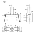
- FIG 3 shows a schematic three-side view of a wave stirrer in a mounted state according to a second embodiment of the present invention.
- the stirrer blades 12 are mounted at the holding device 10 on opposite sides.
- Each of both stirrer blades 12 is hanging at one cantilever 16, respectively.
- the cantilever 16 penetrates the upper part 24 of the cutout 22.
- the mounting grooves 20 engage the lateral edges of the upper part 24.
- the mounting grooves 20 of the second embodiment in FIG 3 are inclined, so that the distances of the mounting grooves 20 from the rotation axis 18 increase with a decreasing height.
- the planes of the stirrer blades 12 extend also along said inclined direction.
- the radial extension R of the stirrer blade 12 is still much smaller than its axial extension A.
- the top view of FIG 3 clarifies the maximum radial extension R of the stirrer blade 12.
- the front view of FIG 3 clarifies the maximum axial extension A of the stirrer blade 12. It is a substantial feature of the present invention, that the maximum axial extension A of the stirrer blade 12 is equal as or bigger than the maximum radial extension R of the stirrer blade 12.
- FIG 4 shows a schematic view of three examples of stirrer blades 12, 26 and 28 according to the present invention.
- the stirrer blades 12, 26 and 28 are formed as plane sheets.
- the first stirrer blade 12 is a rectangular stirrer blade with the cutout 22.
- the cutout 22 of the first stirrer blade 12 is also substantially rectangular and includes the upper part 24.
- the width of said upper part 24 is smaller than the width of the proper cutout 22.
- the second stirrer blade 26 is a triangular stirrer blade with a substantially triangular cutout 22.
- the triangular cutout 22 of the second stirrer blade 26 includes the upper part 24.
- the width of said upper part 24 is smaller than the width of the proper cutout 22.
- the upper parts 24 of the first stirrer blade 12 and the second stirrer blade 26 have contours complementary the cross-section of the cantilever 16 between the two opposing mounting grooves 20.
- the first stirrer blade 12 and the second stirrer blade 26 can be form-locking plugged into the mounting grooves 20.
- the third stirrer blade 28 has a form like an anchor and includes two holes 30. One of the holes 30 is arranged in a central portion of the third stirrer blade 28. The other one of the holes 30 is arranged in an upper portion of the third stirrer blade 28.
- the holes 30 are provided for such a kind of holding devices with a snap-in mechanism.
- FIG 5 shows an original sheet 32 provided for a concurrent cutting of two different stirrer blades 12 and 34 according to the present invention.
- the dashed line within the original sheet 32 illustrates a separating line 38 between the different stirrer blades 12 and 34.
- the stirrer blade 12 corresponds with the stirrer blade of FIG 1 to 3 .
- the stirrer blade 34 is a shaped part with a hole 30 and a slot 36.
- the contour of the cutout 22 and the upper part 24 of the stirrer blade 12 is substantially the same as the contour of the stirrer blade 34.
- the stirrer blades 12 and 34 can be concurrently cut out from the original sheet 32.
- the geometric structures of the stirrer blades 12 and 34 allow an efficient production of both stirrer blades 12 and 34 from one single piece of sheet, i.e. the original sheet 32.
Landscapes
- Engineering & Computer Science (AREA)
- Power Engineering (AREA)
- Physics & Mathematics (AREA)
- Electromagnetism (AREA)
- Constitution Of High-Frequency Heating (AREA)
- Mixers Of The Rotary Stirring Type (AREA)
- Food-Manufacturing Devices (AREA)
Abstract
Description
- The present invention relates to a wave stirrer with a holding device and at least two stirrer blades for a microwave oven. Further, the present invention relates to a microwave oven comprising at least one wave stirrer with a holding device and at least two stirrer blades.
- In household appliances the microwave oven is a very common technology due to its energy efficiency and time savings compared to a conventional oven. The microwaves are reflected by metallic surfaces like the walls of the oven cavity. Thus, interferences cause an uneven distribution of the microwave energy inside the oven cavity, resulting to an uneven heating of food.
- In order to get a more even distribution of the microwave energy inside the oven cavity, the microwave oven is equipped with a wave stirrer. Said wave stirrer is rotatable and made of an electrically conductive material. The wave stirrer is arranged inside the oven cavity in such a way that the rotation has a feedback on the magnetron by periodically altering the wave impedance. This results in small frequency shifts of the electro-magnetic field inside the oven cavity. Since the interference pattern depends on the frequency, the resulting areas of high and low field energy are periodically moved through the oven cavity by the wave stirrer.
- Besides the desired periodic changes of the wave impedance, it would be advantageous, that the wave stirrer does not increase the reflections of the field energy back to the magnetron. This reflected energy cannot be used for heating the food stuff inside the oven cavity.
- The wave stirrer should not have any sharp edges on its surface. Small gaps between the wave stirrer and the metallic surfaces of the oven cavity should be avoided. The sharp edges as well as the small gaps could result in sparks or discharge effects, so that the wave stirrer and the inner wall of the oven cavity can be damaged. A damage of the inner wall of the oven cavity may lead to an unwanted microwave leakage.
- The wave stirrers of the prior art often have a complex geometry, which requires a costly production. However, wave stirrers with a simple geometry and small dimensions do not substantially improve the distribution of the electro-magnetic energy, since the feedback on the magnetron is not high enough.
- It is the object of the present invention to provide a wave stirrer for a microwave oven, which wave stirrer allows an improved distribution of the electro-magnetic energy on the one hand and has a relative simple geometry on the other hand.
- This object is achieved by the wave stirrer for a microwave oven according to claim 1.
- According to the present invention the wave stirrer for the microwave oven comprises:
- a holding device rotatable around a rotation axis (18), and
- at least two stirrer blades arranged at the holding device, wherein
- the holding device is made of at least one dielectric material,
- the stirrer blades are made of at least one conductive material, and
- the maximum axial extension of the stirrer blade along the rotation axis is equal as or bigger than the maximum radial extension of the stirrer blade orthogonal to the rotation axis.
- The core of the present invention is the holding device made of the dielectric material on the one hand and the maximum axial extension of the stirrer blade, which is equal as or bigger than the maximum radial extension of the stirrer blade, on the other hand. This constellation results in a lower danger of hot spots and sparkovers. The inventive wave stirrer can be designed in such a way that the wave impedance of the feed-box is improved. Thus, further tuning elements like stubs are not necessary. This results in compact dimensions of the wave stirrer. The production is easy by low costs.
- According to the preferred embodiment of the present invention the at least one of the stirrer blades is formed as a sheet, in particular the stirrer blades are formed as plane sheets. This contributes to a simple production. The amount of the required metallic material is low.
- In particular, at least two of the stirrer blades are electrically isolated from each other. The electric isolation of the stirrer blades contributes to the lower danger of hot spots and sparkovers.
- For example, at least one of the stirrer blades may comprise a cutout, wherein a smaller part of said cutout is complementary with a cross-section of a part of the holding device. These stirrer blades can be easily detached, cleaned and reassembled by the user.
- Alternatively, at least one of the stirrer blades may comprise at least one hole and/or at least one slot, wherein the hole and/or the slot, respectively, is connected or connectable to a snap-in mechanism of the holding device. The snap-in mechanism allows that the user can detach the stirrer blades in an easy way.
- Preferably, at least one of the stirrer blades is made of at least one metallic material. Further, at least one of the stirrer blades is coated by enamel or ceramic material.
- According to the preferred embodiment of the present invention the rotation axis extends along a vertical direction.
- Further, the holding device comprises at least two cantilevers, wherein the stirrer blade is attached or attachable at one of the cantilevers.
- The cantilever may include at least one mounting groove, so that the cross-section of the cantilever besides said mounting groove is complementary with the smaller part within the cutout of the stirrer blade.
- Preferably, the cantilever may include two opposing mounting grooves, so that the cross-section of the cantilever besides said mounting groove is complementary with the smaller part within the cutout of the stirrer blade.
- Alternatively, the cantilever may comprise at least one snap-in mechanism complementary with at least one hole and/or at least one slot of the stirrer blade.
- Further, the present invention relates to a microwave oven with at least one wave stirrer as described above. Preferably, the microwave oven is provided for a domestic appliance.
- The invention will be explained in more detail below by means of exemplary embodiments. Reference is thereby made to the drawings, wherein
- FIG 1
- shows a schematic perspective view of a wave stirrer in a fragmented state according to a first embodiment of the present invention,
- FIG 2
- shows a schematic three-side view of the wave stirrer in a mounted state according to the first embodiment of the present invention,
- FIG 3
- shows a schematic three-side view of a wave stirrer in a mounted state according to a second embodiment of the present invention,
- FIG 4
- shows a schematic view of three examples of stirrer blades according to the present invention, and
- FIG 5
- shows an original sheet provided for a concurrent cut- ting of two different stirrer blades according to the present invention.
-
FIG 1 shows a schematic perspective view of a wave stirrer in a fragmented state according to a first embodiment of the present invention. The wave stirrer comprises aholding device 10 and twostirrer blades 12. - The
holding device 10 is made of a dielectric material. Preferably, the holdingdevice 10 consists of ceramics or polymers with a high temperature resistance. For example, the holdingdevice 10 is made of LCP. - The holding
device 10 includes ashaft 14 and twocantilevers 16. Theshaft 14 extends concentrically along avertical rotation axis 18. The elongated cantilevers 16 are attached at the lower end of theshaft 14 on opposite sides of saidshaft 14. Thecantilevers 16 extend perpendicularly to theshaft 14 along a common axis. Each of thecantilevers 16 extends from therotation axis 18 along a radial direction. In this example bothcantilevers 16 are formed as a single-piece part. - In their outer portions the
cantilevers 16 include two mountinggrooves 20 in each case. The mountinggrooves 20 are formed as vertical grooves at side walls of thecantilevers 16. The two mountinggrooves 20 of eachcantilever 16 are arranged opposite to each other on different side walls of thecantilevers 16. - The
stirrer blades 12 are at least partially made of an electrically conductive material. Preferably, thestirrer blades 12 are of at least one metallic material. Thestirrer blades 12 can be coated, for example with an enamel or ceramics. - The
stirrer blade 12 is formed as a plane sheet and comprises acutout 22. Thecutout 22 is arranged in a central portion of thestirrer blade 12. Thecutout 22 includes anupper part 24 with a smaller width than theproper cutout 22. Theupper part 24 of thecutout 22 is substantially complementary with the cross-section of thecantilever 16 between the mountinggrooves 20. Thestirrer blade 12 is provided for hanging at thecantilever 16, wherein thecantilever 16 penetrates thecutout 22 and theupper part 24 of thecutout 22 engages the mountinggrooves 20. -
FIG 2 shows a schematic three-side view of the wave stirrer in a mounted state according to the first embodiment of the present invention. Thestirrer blades 12 are mounted at the holdingdevice 10 on opposite sides. Each of the twostirrer blades 12 is hanging at one of the twocantilevers 16, respectively. Thecantilever 16 penetrates theupper part 24 of thecutout 22. The mountinggrooves 20 engage the lateral edges of theupper part 24. - Since the holding
device 10 is made of dielectric material, thestirrer blades 12 are electrically isolated from each other. The planes of thestirrer blades 12 extend substantially along an axial direction of the wave stirrer. Thus, the maximum radial extension of thestirrer blade 12 is much smaller than its maximum axial extension. - The radial extension of the
stirrer blade 12 is defined as its extension along the radial axis of the wave stirrer, i.e. the extension orthogonal to therotation axis 18. The axial extension of thestirrer blade 12 is defined as its extension along the radial axis of the wave stirrer, i.e. the extension along therotation axis 18. -
FIG 3 shows a schematic three-side view of a wave stirrer in a mounted state according to a second embodiment of the present invention. Thestirrer blades 12 are mounted at the holdingdevice 10 on opposite sides. Each of bothstirrer blades 12 is hanging at onecantilever 16, respectively. Thecantilever 16 penetrates theupper part 24 of thecutout 22. The mountinggrooves 20 engage the lateral edges of theupper part 24. - Unlike the vertical mounting
grooves 20 of the first embodiment inFIG 1 andFIG 2 , the mountinggrooves 20 of the second embodiment inFIG 3 are inclined, so that the distances of the mountinggrooves 20 from therotation axis 18 increase with a decreasing height. Thus, the planes of thestirrer blades 12 extend also along said inclined direction. However, the radial extension R of thestirrer blade 12 is still much smaller than its axial extension A. - The top view of
FIG 3 clarifies the maximum radial extension R of thestirrer blade 12. The front view ofFIG 3 clarifies the maximum axial extension A of thestirrer blade 12. It is a substantial feature of the present invention, that the maximum axial extension A of thestirrer blade 12 is equal as or bigger than the maximum radial extension R of thestirrer blade 12. -
FIG 4 shows a schematic view of three examples ofstirrer blades stirrer blades - The
first stirrer blade 12 is a rectangular stirrer blade with thecutout 22. Thecutout 22 of thefirst stirrer blade 12 is also substantially rectangular and includes theupper part 24. The width of saidupper part 24 is smaller than the width of theproper cutout 22. - The
second stirrer blade 26 is a triangular stirrer blade with a substantiallytriangular cutout 22. Thetriangular cutout 22 of thesecond stirrer blade 26 includes theupper part 24. The width of saidupper part 24 is smaller than the width of theproper cutout 22. - The
upper parts 24 of thefirst stirrer blade 12 and thesecond stirrer blade 26 have contours complementary the cross-section of thecantilever 16 between the two opposing mountinggrooves 20. Thus, thefirst stirrer blade 12 and thesecond stirrer blade 26 can be form-locking plugged into the mountinggrooves 20. - The
third stirrer blade 28 has a form like an anchor and includes twoholes 30. One of theholes 30 is arranged in a central portion of thethird stirrer blade 28. The other one of theholes 30 is arranged in an upper portion of thethird stirrer blade 28. Theholes 30 are provided for such a kind of holding devices with a snap-in mechanism. -
FIG 5 shows anoriginal sheet 32 provided for a concurrent cutting of twodifferent stirrer blades original sheet 32 illustrates a separatingline 38 between thedifferent stirrer blades - The
stirrer blade 12 corresponds with the stirrer blade ofFIG 1 to 3 . Thestirrer blade 34 is a shaped part with ahole 30 and aslot 36. - The contour of the
cutout 22 and theupper part 24 of thestirrer blade 12 is substantially the same as the contour of thestirrer blade 34. Thestirrer blades original sheet 32. The geometric structures of thestirrer blades stirrer blades original sheet 32. -
- 10
- holding device
- 12
- stirrer blade
- 14
- shaft
- 16
- cantilever
- 18
- rotation axis
- 20
- mounting grove
- 22
- cutout
- 24
- upper part
- 26
- stirrer blade
- 28
- stirrer blade
- 30
- hole
- 32
- original sheet
- 34
- stirrer blade
- 36
- slot
- 38
- separating line
Claims (15)
- A wave stirrer for a microwave oven, which wave stirrer comprises:- a holding device (10) rotatable around a rotation axis (18), and- at least two stirrer blades (12; 26; 28; 34) arranged at the holding device (10), wherein- the holding device (10) is made of at least one dielectric material,- the stirrer blades (12; 26; 28; 34) are made of at least one conductive material, and- the maximum axial extension (A) of the stirrer blade (12; 26; 28; 34) along the rotation axis (18) is equal as or bigger than the maximum radial extension (R) of the stirrer blade (12; 26; 28; 34) orthogonal to the rotation axis (18).
- The wave stirrer according to claim 1,
characterized in that
at least one of the stirrer blades (12; 26; 28; 34) is formed as a sheet. - The wave stirrer according to claim 2,
characterized in that
at least one of the stirrer blades (12; 26; 28; 34) is formed as a plane sheet. - The wave stirrer according to any one of the preceding claims,
characterized in that
at least two of the stirrer blades (12; 26; 28; 34) are electrically isolated from each other. - The wave stirrer according to any one of the preceding claims,
characterized in that
at least one of the stirrer blades (12; 26; 28; 34) comprises a cutout (22), wherein a smaller part (24) of said cutout (22) is complementary with a cross-section of a part of the holding device (10). - The wave stirrer according to any one of the claims 1 to 4,
characterized in that
at least one of the stirrer blades (12; 26; 28; 34) comprises at least one hole (30) and/or at least one slot (36), wherein the hole (30) and/or the slot (36), respectively, is connected or connectable to a snap-in mechanism of the holding device (10). - The wave stirrer according to any one of the preceding claims,
characterized in that
at least one of the stirrer blades (12; 26; 28; 34) is made of at least one metallic material. - The wave stirrer according to any one of the preceding claims,
characterized in that
at least one of the stirrer blades (12; 26; 28; 34) is coated by enamel or ceramic material. - The wave stirrer according to any one of the preceding claims,
characterized in that
the rotation axis (18) extends along a vertical direction. - The wave stirrer according to any one of the preceding claims,
characterized in that
the holding device (10) comprises at least two cantilevers (16), wherein the stirrer blade (12; 26; 28; 34) is attached or attachable at the cantilever. - The wave stirrer according to claim 10, as far as related to any one of the claims 5 to 9,
characterized in that
the cantilever (16) includes at least one mounting groove (20), so that the cross-section of the cantilever (16) besides said mounting groove (20) is complementary with the smaller part (24) within the cutout (22) of the stirrer blade (12; 26; 28; 34). - The wave stirrer according to claim 10 or 11, as far as related to any one of the claims 5 to 9,
characterized in that
the cantilever (16) includes two opposing mounting grooves (20), so that the cross-section of the cantilever (16) besides said mounting groove (20) is complementary with the smaller part (24) within the cutout (22) of the stirrer blade (12; 26; 28; 34). - The wave stirrer according to any one of the claims 10 to 12,
characterized in that
the cantilever (16) comprises at least one snap-in mechanism complementary with at least one hole (30) and/or at least one slot (36) of the stirrer blade (12; 26; 28; 34), respectively. - A microwave oven with at least one wave stirrer,
characterized in that
the microwave oven comprises at least one wave stirrer according to any one of the claims 1 to 13. - The microwave oven according to claim 14,
characterized in that
the microwave oven is provided for a domestic appliance.
Priority Applications (7)
| Application Number | Priority Date | Filing Date | Title |
|---|---|---|---|
| AT09010695T ATE528958T1 (en) | 2009-08-20 | 2009-08-20 | SHAFT MIXER FOR A MICROWAVE OVEN |
| EP09010695A EP2288232B1 (en) | 2009-08-20 | 2009-08-20 | A wave stirrer for a microwave oven |
| US13/498,986 US20120199580A1 (en) | 2009-08-20 | 2010-07-16 | wave stirrer for a microwave oven |
| CN201080045756.8A CN102577600B (en) | 2009-08-20 | 2010-07-16 | A wave stirrer for a microwave oven |
| AU2010285267A AU2010285267B2 (en) | 2009-08-20 | 2010-07-16 | A wave stirrer for a microwave oven |
| CA2774882A CA2774882A1 (en) | 2009-08-20 | 2010-07-16 | A wave stirrer for a microwave oven |
| PCT/EP2010/004343 WO2011020531A1 (en) | 2009-08-20 | 2010-07-16 | A wave stirrer for a microwave oven |
Applications Claiming Priority (1)
| Application Number | Priority Date | Filing Date | Title |
|---|---|---|---|
| EP09010695A EP2288232B1 (en) | 2009-08-20 | 2009-08-20 | A wave stirrer for a microwave oven |
Publications (2)
| Publication Number | Publication Date |
|---|---|
| EP2288232A1 true EP2288232A1 (en) | 2011-02-23 |
| EP2288232B1 EP2288232B1 (en) | 2011-10-12 |
Family
ID=41426182
Family Applications (1)
| Application Number | Title | Priority Date | Filing Date |
|---|---|---|---|
| EP09010695A Not-in-force EP2288232B1 (en) | 2009-08-20 | 2009-08-20 | A wave stirrer for a microwave oven |
Country Status (7)
| Country | Link |
|---|---|
| US (1) | US20120199580A1 (en) |
| EP (1) | EP2288232B1 (en) |
| CN (1) | CN102577600B (en) |
| AT (1) | ATE528958T1 (en) |
| AU (1) | AU2010285267B2 (en) |
| CA (1) | CA2774882A1 (en) |
| WO (1) | WO2011020531A1 (en) |
Cited By (1)
| Publication number | Priority date | Publication date | Assignee | Title |
|---|---|---|---|---|
| BE1020505A3 (en) * | 2012-05-10 | 2013-11-05 | Halm Bvba | MICROWAVES WITH OPTICAL CONTROL. |
Families Citing this family (4)
| Publication number | Priority date | Publication date | Assignee | Title |
|---|---|---|---|---|
| CN102933905B (en) * | 2010-05-26 | 2015-04-01 | Lg电子株式会社 | cooking device |
| US11412584B2 (en) | 2017-12-08 | 2022-08-09 | Alkar-Rapidpak, Inc. | Ovens with metallic belts and microwave launch box assemblies for processing food products |
| CN110864334A (en) * | 2019-11-25 | 2020-03-06 | 朱小菊 | Moisture-keeping microwave oven |
| US12563647B2 (en) | 2021-04-26 | 2026-02-24 | Alkar-Rapidpak, Inc. | Food processing machines with microwave heating systems and microwave suppression systems |
Citations (4)
| Publication number | Priority date | Publication date | Assignee | Title |
|---|---|---|---|---|
| DE1118378B (en) * | 1960-06-25 | 1961-11-30 | Mikrowellen Ges M B H Deutsche | Arrangement for distributing the radiated RF energy in a microwave workspace |
| FR2268427A1 (en) * | 1974-04-17 | 1975-11-14 | Matsushita Electric Industrial Co Ltd | |
| US3920944A (en) * | 1970-08-18 | 1975-11-18 | Hirst Microwave Ind Limited | Method of cooking food employing both microwave and heat energy |
| US5043547A (en) * | 1990-03-21 | 1991-08-27 | Goldstar Co., Ltd. | Temperature sensor connecting device for microwave oven |
Family Cites Families (90)
| Publication number | Priority date | Publication date | Assignee | Title |
|---|---|---|---|---|
| US1509953A (en) * | 1918-12-30 | 1924-09-30 | Westinghouse Electric & Mfg Co | Fan |
| US1421932A (en) * | 1920-06-09 | 1922-07-04 | John C Foster | Spring-operated motor |
| US1658460A (en) * | 1923-12-07 | 1928-02-07 | Pfaudler Co Inc | Rotary agitator |
| US1797828A (en) * | 1928-08-14 | 1931-03-24 | Hinton Henry | Self-serving table |
| US2813185A (en) * | 1954-03-08 | 1957-11-12 | Raytheon Mfg Co | Heating devices |
| US2920174A (en) * | 1957-06-28 | 1960-01-05 | Raytheon Co | Microwave ovens |
| US3364332A (en) * | 1964-03-20 | 1968-01-16 | Philips Corp | Arrangement in microwave stoves |
| US3373930A (en) * | 1966-04-29 | 1968-03-19 | Gen Motors Corp | Fan structure |
| US3480373A (en) * | 1966-11-01 | 1969-11-25 | Cooling Dev Ltd | Fans |
| US3531950A (en) * | 1968-09-17 | 1970-10-06 | Amana Refrigeration Inc | Friction drive for slow speed motor |
| US3608976A (en) * | 1969-09-12 | 1971-09-28 | Fines A Zugelder | Fan blade having wear-resistant ribs and fan including a plurality of same |
| JPS4919598B1 (en) * | 1970-05-30 | 1974-05-18 | ||
| US3692967A (en) * | 1970-10-06 | 1972-09-19 | Tokyo Shibaura Electric Co | High-frequency heating apparatus having electromagnetic wave agitating device |
| US3783219A (en) * | 1970-11-11 | 1974-01-01 | Sharp Kk | Air cooled microwave cooking oven and door |
| US3878350A (en) * | 1971-07-15 | 1975-04-15 | Sharp Kk | Microwave cooking apparatus |
| US3758737A (en) * | 1972-06-13 | 1973-09-11 | Amana Refrigeration Inc | Waveguide filter for microwave heating apparatus |
| US3884213A (en) * | 1973-03-30 | 1975-05-20 | Donald P Smith | Cooking apparatus |
| US3867605A (en) * | 1973-08-06 | 1975-02-18 | Welbuilt Corp | Microwave oven |
| US3934106A (en) * | 1973-09-10 | 1976-01-20 | Raytheon Company | Microwave browning means |
| US3857009A (en) * | 1973-09-10 | 1974-12-24 | Raytheon Co | Microwave browning means |
| US3859493A (en) * | 1973-11-21 | 1975-01-07 | Raytheon Co | Microwave heating temperature control |
| US3975606A (en) * | 1973-12-18 | 1976-08-17 | Matsushita Electric Industrial Co., Ltd. | Microwave oven with uniform electric field distribution |
| US3936627A (en) * | 1974-01-17 | 1976-02-03 | General Electric Company | Microwave oven with special rack designs |
| US3939320A (en) * | 1974-04-12 | 1976-02-17 | Micro-Tronics, Inc. | Beam stirrer |
| US4092512A (en) * | 1975-08-27 | 1978-05-30 | Matsushita Electric Industrial Co. Ltd. | Turntable drive mechanism in electronic oven |
| US4136271A (en) * | 1976-02-03 | 1979-01-23 | Matsushita Electric Industrial Co., Ltd. | Microwave oven |
| US4163141A (en) * | 1976-04-14 | 1979-07-31 | Matsushita Electric Industrial Co., Ltd. | Microwave oven |
| JPS5312535A (en) * | 1976-07-20 | 1978-02-04 | Toshiba Corp | Microwave heating unit |
| GB1589466A (en) * | 1976-07-29 | 1981-05-13 | Atomic Energy Authority Uk | Treatment of substances |
| US4133997A (en) * | 1977-02-09 | 1979-01-09 | Litton Systems, Inc. | Dual feed, horizontally polarized microwave oven |
| USRE31637E (en) * | 1977-05-13 | 1984-07-31 | Sanyo Electric Co., Ltd. | Combination microwave and gas oven |
| US4211909A (en) * | 1978-05-15 | 1980-07-08 | Sanyo Electric Co., Ltd. | Combination microwave and gas oven |
| US4151792A (en) * | 1977-12-20 | 1979-05-01 | Nearhood Thomas C | Cooker-mixer apparatus |
| US4158760A (en) * | 1977-12-30 | 1979-06-19 | Raytheon Company | Seed heating microwave appliance |
| US4166208A (en) * | 1978-03-27 | 1979-08-28 | Raytheon Company | Corn popper with butter dispenser |
| JPS5759850Y2 (en) * | 1978-07-13 | 1982-12-21 | ||
| US4421968A (en) * | 1978-12-01 | 1983-12-20 | Raytheon Company | Microwave oven having rotating conductive radiators |
| US4223194A (en) * | 1978-12-26 | 1980-09-16 | General Electric Company | Microwave oven with means for modifying energy distribution therein |
| US4286135A (en) * | 1979-10-09 | 1981-08-25 | Raytheon Company | Compact microwave isolator |
| US4289945A (en) * | 1979-10-17 | 1981-09-15 | Whirlpool Corporation | Energy transmission and distribution system for a microwave oven |
| US4296297A (en) * | 1979-12-26 | 1981-10-20 | General Electric Company | Drive arrangement for microwave oven mode stirrer |
| US4390768A (en) * | 1980-09-24 | 1983-06-28 | Raytheon Company | Cook-by-weight microwave oven |
| JPS57189493A (en) * | 1981-05-15 | 1982-11-20 | Matsushita Electric Industrial Co Ltd | High frequency heater |
| JPS5885125A (en) * | 1981-11-16 | 1983-05-21 | Toshiba Corp | Electronic oven |
| US4434343A (en) * | 1982-01-15 | 1984-02-28 | Raytheon Company | Turntable for microwave oven |
| US4554195A (en) * | 1982-06-10 | 1985-11-19 | Wilbanks International, Inc. | Ceramic coated abrasion resistant member and process for making |
| US4671740A (en) * | 1982-06-10 | 1987-06-09 | Wilbanks International, Inc. | Ceramic coated abrasion resistant member and process for making |
| US4629849A (en) * | 1984-06-28 | 1986-12-16 | Ngk Insulators Ltd. | Microwave heating device having a rotary reflector means in a heating chamber |
| US4580023A (en) * | 1985-03-06 | 1986-04-01 | Amana Refrigeration, Inc. | Microwave oven with circular polarization |
| US4596915A (en) * | 1985-05-07 | 1986-06-24 | Amana Refrigeration, Inc. | Microwave oven having resonant antenna |
| US4556772A (en) * | 1985-05-07 | 1985-12-03 | Amana Refrigeration, Inc. | Microwave oven cavity air flow system |
| US4618756A (en) * | 1985-07-08 | 1986-10-21 | Whirlpool Corporation | Air circulation system for microwave oven |
| US4641006A (en) * | 1985-09-30 | 1987-02-03 | The Maytag Company | Rotating antenna for a microwave oven |
| JPS62158790U (en) * | 1986-03-29 | 1987-10-08 | ||
| US4714811A (en) * | 1986-07-18 | 1987-12-22 | Jova Enterprises, Inc. | Microwave oven and method with controlled heating profile |
| KR890001581Y1 (en) * | 1986-07-21 | 1989-04-06 | 삼성전자주식회사 | High frequency dispersion fan auxiliary wing mounting device of microwave oven |
| US4963709A (en) * | 1987-07-24 | 1990-10-16 | The United States Of America As Represented By The Department Of Energy | Method and device for microwave sintering large ceramic articles |
| US4765066A (en) * | 1987-08-19 | 1988-08-23 | Vbe Inc. | Microwave clothes dryer |
| US4764651A (en) * | 1987-09-23 | 1988-08-16 | Whirlpool Corporation | Grounding of stirrer bushing in a microwave oven |
| US4904834A (en) * | 1987-10-16 | 1990-02-27 | Raytheon Company | Mixing attachment for microwave oven turntables |
| US5013158A (en) * | 1988-09-29 | 1991-05-07 | Tarlow Kenneth A | Self stirring vessel |
| KR920004977Y1 (en) * | 1990-05-29 | 1992-07-25 | 삼성전자 주식회사 | Electronic range |
| EP0522231B1 (en) * | 1991-07-11 | 1998-09-16 | Kawasaki Jukogyo Kabushiki Kaisha | Method of and apparatus for treating infectious medical wastes |
| US5378875A (en) * | 1991-12-25 | 1995-01-03 | Mitsubishi Materials Corporation | Microwave oven with power detecting device |
| AU653291B2 (en) * | 1992-06-01 | 1994-09-22 | Matsushita Electric Industrial Co., Ltd. | Heating cooking device |
| US5271673A (en) * | 1992-08-24 | 1993-12-21 | Bohnet Irma M | Spring operated stirring apparatus |
| KR0140501B1 (en) * | 1993-05-27 | 1998-06-01 | 김광호 | microwave |
| US5765947A (en) * | 1996-03-22 | 1998-06-16 | Dubroy; Gary P. | Wind-up pot stirrer having spring tension and gear train mechanism |
| US5601070A (en) * | 1996-06-17 | 1997-02-11 | Middleby Marshall, Inc. | Convection oven |
| JP3942248B2 (en) * | 1997-02-24 | 2007-07-11 | 富士通株式会社 | Heat sink and information processing apparatus equipped with the same |
| US6013909A (en) * | 1997-03-10 | 2000-01-11 | Sharp Kabushiki Kaisha | Portable microwave oven having a door with stirrer |
| US5850074A (en) * | 1997-08-30 | 1998-12-15 | Daewoo Electronics Co., Ltd. | Microwave oven equipped with a microwave generating apparatus designed to reduce secondary electron emission |
| CN1213058A (en) * | 1997-09-29 | 1999-04-07 | 三星电子株式会社 | Stirrer for use in microwave oven |
| CN1124443C (en) * | 1998-05-13 | 2003-10-15 | 三星电子株式会社 | Microwave oven having improved structure for fixing blower |
| WO2000018191A1 (en) * | 1998-09-18 | 2000-03-30 | Marc Seghatol | Microwave polymerization system for dentistry |
| US6070519A (en) * | 1998-12-15 | 2000-06-06 | Sham; John C. K. | Juice extractor and beverage mixer apparatus |
| GB0015922D0 (en) * | 2000-06-30 | 2000-08-23 | Apollo Microwave Ovens Limited | Improvements in or relating to microwave ovens |
| US6723961B2 (en) * | 2000-08-29 | 2004-04-20 | Maytag Corporation | Self-cleaning system for convection cooking appliance |
| ITMI20010120A1 (en) * | 2001-01-23 | 2002-07-23 | Itel Telecomunicazioni S R L | MICROWAVE SYSTEM FOR THE RECOVERY OF BILOGIC PESTS |
| TW530891U (en) * | 2002-06-19 | 2003-05-01 | Shiang-Heng Tang | Improved blade for ceiling fan |
| EP1547444B1 (en) * | 2002-10-04 | 2014-09-17 | Microwave Ovens Limited | Improvements in or relating to microwave ovens |
| US6933484B2 (en) * | 2003-03-05 | 2005-08-23 | Jeffrey A. Lindley | Microwave oven with food stirring device |
| KR100988570B1 (en) * | 2003-04-10 | 2010-10-19 | 삼성전자주식회사 | Heating cooker |
| CN1540213A (en) * | 2003-04-25 | 2004-10-27 | 乐金电子(天津)电器有限公司 | Structure of installing agitation fan in microwave oven |
| US20060067814A1 (en) * | 2004-09-30 | 2006-03-30 | Jia-Yeh Wang | Cooling fan with anti-friction shaft and bearing set |
| BRPI0617109A2 (en) * | 2005-08-29 | 2011-07-12 | Du Pont | susceptor assemblies, methods for heating a food product and field guide structures |
| KR100761295B1 (en) * | 2006-10-27 | 2007-09-27 | 엘지전자 주식회사 | Cooker |
| CN201007511Y (en) * | 2007-01-31 | 2008-01-16 | 美的集团有限公司 | flat panel microwave |
| CN201181030Y (en) * | 2007-09-19 | 2009-01-14 | 王翔 | Microwave oven |
| US20110048246A1 (en) * | 2009-08-27 | 2011-03-03 | Kuei-Tang Chang | Inner pot assembly for hot-air baking oven and hot-air baking oven having such assembly |
-
2009
- 2009-08-20 AT AT09010695T patent/ATE528958T1/en not_active IP Right Cessation
- 2009-08-20 EP EP09010695A patent/EP2288232B1/en not_active Not-in-force
-
2010
- 2010-07-16 CA CA2774882A patent/CA2774882A1/en not_active Abandoned
- 2010-07-16 CN CN201080045756.8A patent/CN102577600B/en not_active Expired - Fee Related
- 2010-07-16 US US13/498,986 patent/US20120199580A1/en not_active Abandoned
- 2010-07-16 AU AU2010285267A patent/AU2010285267B2/en not_active Ceased
- 2010-07-16 WO PCT/EP2010/004343 patent/WO2011020531A1/en not_active Ceased
Patent Citations (4)
| Publication number | Priority date | Publication date | Assignee | Title |
|---|---|---|---|---|
| DE1118378B (en) * | 1960-06-25 | 1961-11-30 | Mikrowellen Ges M B H Deutsche | Arrangement for distributing the radiated RF energy in a microwave workspace |
| US3920944A (en) * | 1970-08-18 | 1975-11-18 | Hirst Microwave Ind Limited | Method of cooking food employing both microwave and heat energy |
| FR2268427A1 (en) * | 1974-04-17 | 1975-11-14 | Matsushita Electric Industrial Co Ltd | |
| US5043547A (en) * | 1990-03-21 | 1991-08-27 | Goldstar Co., Ltd. | Temperature sensor connecting device for microwave oven |
Cited By (1)
| Publication number | Priority date | Publication date | Assignee | Title |
|---|---|---|---|---|
| BE1020505A3 (en) * | 2012-05-10 | 2013-11-05 | Halm Bvba | MICROWAVES WITH OPTICAL CONTROL. |
Also Published As
| Publication number | Publication date |
|---|---|
| CN102577600A (en) | 2012-07-11 |
| WO2011020531A1 (en) | 2011-02-24 |
| AU2010285267A1 (en) | 2012-05-17 |
| EP2288232B1 (en) | 2011-10-12 |
| CN102577600B (en) | 2014-04-23 |
| AU2010285267B2 (en) | 2014-07-17 |
| CA2774882A1 (en) | 2011-02-24 |
| US20120199580A1 (en) | 2012-08-09 |
| ATE528958T1 (en) | 2011-10-15 |
Similar Documents
| Publication | Publication Date | Title |
|---|---|---|
| EP2288232B1 (en) | A wave stirrer for a microwave oven | |
| EP3111724B1 (en) | Microwave oven having a physically adjustable waveguide dynamically displaced by a movement control means | |
| CA1159905A (en) | Microwave oven excitation system capable of giving an asymmetric rotating field | |
| JP6288461B2 (en) | Microwave processing equipment | |
| CN106231712B (en) | Antenna assembly of microwave oven and microwave oven | |
| EP3384731B1 (en) | Microwave oven | |
| KR900008545B1 (en) | Electromagnetic range with heater | |
| WO2015118101A1 (en) | Microwave-energy feeding arrangement, microwave heating arrangement, microwave oven, method for manufacturing a microwave oven and method for heating food | |
| JP2014216067A (en) | High-frequency wave heating device | |
| JP5467330B2 (en) | Microwave heating device | |
| CN221197474U (en) | Cooking utensil | |
| JP4164934B2 (en) | Variable impedance unit | |
| WO2018050098A1 (en) | Antenna assembly for microwave oven, and microwave oven | |
| KR890004874Y1 (en) | Circular mode stirrer | |
| KR20050036439A (en) | A structure of lower plate of cavity for microwave oven | |
| CN216602601U (en) | Detachable stirring cutter and food cooking device | |
| CN205102196U (en) | Microwave oven | |
| JP5402406B2 (en) | microwave | |
| CN117374546A (en) | Waveguide structures, microwave components and cooking appliances | |
| JP4966648B2 (en) | Microwave heating device | |
| CN206361740U (en) | A kind of micro-wave oven | |
| CN117423976A (en) | Antenna components and cooking utensils | |
| KR100302915B1 (en) | Waveguide of microwave oven | |
| JP2007141538A (en) | Microwave heating device | |
| CN116471717A (en) | cooking utensils |
Legal Events
| Date | Code | Title | Description |
|---|---|---|---|
| PUAI | Public reference made under article 153(3) epc to a published international application that has entered the european phase |
Free format text: ORIGINAL CODE: 0009012 |
|
| 17P | Request for examination filed |
Effective date: 20100206 |
|
| AK | Designated contracting states |
Kind code of ref document: A1 Designated state(s): AT BE BG CH CY CZ DE DK EE ES FI FR GB GR HR HU IE IS IT LI LT LU LV MC MK MT NL NO PL PT RO SE SI SK SM TR |
|
| AX | Request for extension of the european patent |
Extension state: AL BA RS |
|
| RAP1 | Party data changed (applicant data changed or rights of an application transferred) |
Owner name: ELECTROLUX HOME PRODUCTS CORPORATION N.V. |
|
| GRAP | Despatch of communication of intention to grant a patent |
Free format text: ORIGINAL CODE: EPIDOSNIGR1 |
|
| RAP1 | Party data changed (applicant data changed or rights of an application transferred) |
Owner name: ELECTROLUX HOME PRODUCTS CORPORATION N.V. |
|
| GRAS | Grant fee paid |
Free format text: ORIGINAL CODE: EPIDOSNIGR3 |
|
| GRAA | (expected) grant |
Free format text: ORIGINAL CODE: 0009210 |
|
| AK | Designated contracting states |
Kind code of ref document: B1 Designated state(s): AT BE BG CH CY CZ DE DK EE ES FI FR GB GR HR HU IE IS IT LI LT LU LV MC MK MT NL NO PL PT RO SE SI SK SM TR |
|
| REG | Reference to a national code |
Ref country code: GB Ref legal event code: FG4D |
|
| REG | Reference to a national code |
Ref country code: CH Ref legal event code: EP |
|
| REG | Reference to a national code |
Ref country code: IE Ref legal event code: FG4D |
|
| REG | Reference to a national code |
Ref country code: DE Ref legal event code: R096 Ref document number: 602009002983 Country of ref document: DE Effective date: 20111215 |
|
| REG | Reference to a national code |
Ref country code: SE Ref legal event code: TRGR |
|
| REG | Reference to a national code |
Ref country code: NL Ref legal event code: VDEP Effective date: 20111012 |
|
| LTIE | Lt: invalidation of european patent or patent extension |
Effective date: 20111012 |
|
| REG | Reference to a national code |
Ref country code: AT Ref legal event code: MK05 Ref document number: 528958 Country of ref document: AT Kind code of ref document: T Effective date: 20111012 |
|
| PG25 | Lapsed in a contracting state [announced via postgrant information from national office to epo] |
Ref country code: BE Free format text: LAPSE BECAUSE OF FAILURE TO SUBMIT A TRANSLATION OF THE DESCRIPTION OR TO PAY THE FEE WITHIN THE PRESCRIBED TIME-LIMIT Effective date: 20111012 Ref country code: NO Free format text: LAPSE BECAUSE OF FAILURE TO SUBMIT A TRANSLATION OF THE DESCRIPTION OR TO PAY THE FEE WITHIN THE PRESCRIBED TIME-LIMIT Effective date: 20120112 Ref country code: LT Free format text: LAPSE BECAUSE OF FAILURE TO SUBMIT A TRANSLATION OF THE DESCRIPTION OR TO PAY THE FEE WITHIN THE PRESCRIBED TIME-LIMIT Effective date: 20111012 Ref country code: IS Free format text: LAPSE BECAUSE OF FAILURE TO SUBMIT A TRANSLATION OF THE DESCRIPTION OR TO PAY THE FEE WITHIN THE PRESCRIBED TIME-LIMIT Effective date: 20120212 |
|
| PG25 | Lapsed in a contracting state [announced via postgrant information from national office to epo] |
Ref country code: PT Free format text: LAPSE BECAUSE OF FAILURE TO SUBMIT A TRANSLATION OF THE DESCRIPTION OR TO PAY THE FEE WITHIN THE PRESCRIBED TIME-LIMIT Effective date: 20120213 Ref country code: SI Free format text: LAPSE BECAUSE OF FAILURE TO SUBMIT A TRANSLATION OF THE DESCRIPTION OR TO PAY THE FEE WITHIN THE PRESCRIBED TIME-LIMIT Effective date: 20111012 Ref country code: HR Free format text: LAPSE BECAUSE OF FAILURE TO SUBMIT A TRANSLATION OF THE DESCRIPTION OR TO PAY THE FEE WITHIN THE PRESCRIBED TIME-LIMIT Effective date: 20111012 Ref country code: GR Free format text: LAPSE BECAUSE OF FAILURE TO SUBMIT A TRANSLATION OF THE DESCRIPTION OR TO PAY THE FEE WITHIN THE PRESCRIBED TIME-LIMIT Effective date: 20120113 Ref country code: NL Free format text: LAPSE BECAUSE OF FAILURE TO SUBMIT A TRANSLATION OF THE DESCRIPTION OR TO PAY THE FEE WITHIN THE PRESCRIBED TIME-LIMIT Effective date: 20111012 Ref country code: LV Free format text: LAPSE BECAUSE OF FAILURE TO SUBMIT A TRANSLATION OF THE DESCRIPTION OR TO PAY THE FEE WITHIN THE PRESCRIBED TIME-LIMIT Effective date: 20111012 |
|
| PG25 | Lapsed in a contracting state [announced via postgrant information from national office to epo] |
Ref country code: CY Free format text: LAPSE BECAUSE OF FAILURE TO SUBMIT A TRANSLATION OF THE DESCRIPTION OR TO PAY THE FEE WITHIN THE PRESCRIBED TIME-LIMIT Effective date: 20111012 |
|
| PG25 | Lapsed in a contracting state [announced via postgrant information from national office to epo] |
Ref country code: EE Free format text: LAPSE BECAUSE OF FAILURE TO SUBMIT A TRANSLATION OF THE DESCRIPTION OR TO PAY THE FEE WITHIN THE PRESCRIBED TIME-LIMIT Effective date: 20111012 Ref country code: CZ Free format text: LAPSE BECAUSE OF FAILURE TO SUBMIT A TRANSLATION OF THE DESCRIPTION OR TO PAY THE FEE WITHIN THE PRESCRIBED TIME-LIMIT Effective date: 20111012 Ref country code: SK Free format text: LAPSE BECAUSE OF FAILURE TO SUBMIT A TRANSLATION OF THE DESCRIPTION OR TO PAY THE FEE WITHIN THE PRESCRIBED TIME-LIMIT Effective date: 20111012 Ref country code: BG Free format text: LAPSE BECAUSE OF FAILURE TO SUBMIT A TRANSLATION OF THE DESCRIPTION OR TO PAY THE FEE WITHIN THE PRESCRIBED TIME-LIMIT Effective date: 20120112 Ref country code: DK Free format text: LAPSE BECAUSE OF FAILURE TO SUBMIT A TRANSLATION OF THE DESCRIPTION OR TO PAY THE FEE WITHIN THE PRESCRIBED TIME-LIMIT Effective date: 20111012 |
|
| PLBE | No opposition filed within time limit |
Free format text: ORIGINAL CODE: 0009261 |
|
| STAA | Information on the status of an ep patent application or granted ep patent |
Free format text: STATUS: NO OPPOSITION FILED WITHIN TIME LIMIT |
|
| PG25 | Lapsed in a contracting state [announced via postgrant information from national office to epo] |
Ref country code: PL Free format text: LAPSE BECAUSE OF FAILURE TO SUBMIT A TRANSLATION OF THE DESCRIPTION OR TO PAY THE FEE WITHIN THE PRESCRIBED TIME-LIMIT Effective date: 20111012 Ref country code: IT Free format text: LAPSE BECAUSE OF FAILURE TO SUBMIT A TRANSLATION OF THE DESCRIPTION OR TO PAY THE FEE WITHIN THE PRESCRIBED TIME-LIMIT Effective date: 20111012 Ref country code: RO Free format text: LAPSE BECAUSE OF FAILURE TO SUBMIT A TRANSLATION OF THE DESCRIPTION OR TO PAY THE FEE WITHIN THE PRESCRIBED TIME-LIMIT Effective date: 20111012 |
|
| 26N | No opposition filed |
Effective date: 20120713 |
|
| REG | Reference to a national code |
Ref country code: DE Ref legal event code: R097 Ref document number: 602009002983 Country of ref document: DE Effective date: 20120713 |
|
| PG25 | Lapsed in a contracting state [announced via postgrant information from national office to epo] |
Ref country code: AT Free format text: LAPSE BECAUSE OF FAILURE TO SUBMIT A TRANSLATION OF THE DESCRIPTION OR TO PAY THE FEE WITHIN THE PRESCRIBED TIME-LIMIT Effective date: 20111012 |
|
| PG25 | Lapsed in a contracting state [announced via postgrant information from national office to epo] |
Ref country code: MC Free format text: LAPSE BECAUSE OF NON-PAYMENT OF DUE FEES Effective date: 20120831 |
|
| REG | Reference to a national code |
Ref country code: SE Ref legal event code: EUG |
|
| PG25 | Lapsed in a contracting state [announced via postgrant information from national office to epo] |
Ref country code: SE Free format text: LAPSE BECAUSE OF NON-PAYMENT OF DUE FEES Effective date: 20120821 Ref country code: ES Free format text: LAPSE BECAUSE OF FAILURE TO SUBMIT A TRANSLATION OF THE DESCRIPTION OR TO PAY THE FEE WITHIN THE PRESCRIBED TIME-LIMIT Effective date: 20120123 |
|
| REG | Reference to a national code |
Ref country code: FR Ref legal event code: ST Effective date: 20130430 |
|
| REG | Reference to a national code |
Ref country code: IE Ref legal event code: MM4A |
|
| PG25 | Lapsed in a contracting state [announced via postgrant information from national office to epo] |
Ref country code: FI Free format text: LAPSE BECAUSE OF FAILURE TO SUBMIT A TRANSLATION OF THE DESCRIPTION OR TO PAY THE FEE WITHIN THE PRESCRIBED TIME-LIMIT Effective date: 20111012 |
|
| PG25 | Lapsed in a contracting state [announced via postgrant information from national office to epo] |
Ref country code: IE Free format text: LAPSE BECAUSE OF NON-PAYMENT OF DUE FEES Effective date: 20120820 |
|
| PG25 | Lapsed in a contracting state [announced via postgrant information from national office to epo] |
Ref country code: FR Free format text: LAPSE BECAUSE OF NON-PAYMENT OF DUE FEES Effective date: 20120831 |
|
| PG25 | Lapsed in a contracting state [announced via postgrant information from national office to epo] |
Ref country code: MT Free format text: LAPSE BECAUSE OF FAILURE TO SUBMIT A TRANSLATION OF THE DESCRIPTION OR TO PAY THE FEE WITHIN THE PRESCRIBED TIME-LIMIT Effective date: 20111012 |
|
| REG | Reference to a national code |
Ref country code: CH Ref legal event code: PL |
|
| GBPC | Gb: european patent ceased through non-payment of renewal fee |
Effective date: 20130820 |
|
| PG25 | Lapsed in a contracting state [announced via postgrant information from national office to epo] |
Ref country code: TR Free format text: LAPSE BECAUSE OF FAILURE TO SUBMIT A TRANSLATION OF THE DESCRIPTION OR TO PAY THE FEE WITHIN THE PRESCRIBED TIME-LIMIT Effective date: 20111012 Ref country code: CH Free format text: LAPSE BECAUSE OF NON-PAYMENT OF DUE FEES Effective date: 20130831 Ref country code: LI Free format text: LAPSE BECAUSE OF NON-PAYMENT OF DUE FEES Effective date: 20130831 |
|
| PG25 | Lapsed in a contracting state [announced via postgrant information from national office to epo] |
Ref country code: LU Free format text: LAPSE BECAUSE OF NON-PAYMENT OF DUE FEES Effective date: 20120820 Ref country code: SM Free format text: LAPSE BECAUSE OF FAILURE TO SUBMIT A TRANSLATION OF THE DESCRIPTION OR TO PAY THE FEE WITHIN THE PRESCRIBED TIME-LIMIT Effective date: 20111012 |
|
| PG25 | Lapsed in a contracting state [announced via postgrant information from national office to epo] |
Ref country code: HU Free format text: LAPSE BECAUSE OF FAILURE TO SUBMIT A TRANSLATION OF THE DESCRIPTION OR TO PAY THE FEE WITHIN THE PRESCRIBED TIME-LIMIT Effective date: 20090820 Ref country code: GB Free format text: LAPSE BECAUSE OF NON-PAYMENT OF DUE FEES Effective date: 20130820 |
|
| PG25 | Lapsed in a contracting state [announced via postgrant information from national office to epo] |
Ref country code: MK Free format text: LAPSE BECAUSE OF FAILURE TO SUBMIT A TRANSLATION OF THE DESCRIPTION OR TO PAY THE FEE WITHIN THE PRESCRIBED TIME-LIMIT Effective date: 20111012 |
|
| PGFP | Annual fee paid to national office [announced via postgrant information from national office to epo] |
Ref country code: DE Payment date: 20220819 Year of fee payment: 14 |
|
| P01 | Opt-out of the competence of the unified patent court (upc) registered |
Effective date: 20230625 |
|
| REG | Reference to a national code |
Ref country code: DE Ref legal event code: R082 Ref document number: 602009002983 Country of ref document: DE |
|
| REG | Reference to a national code |
Ref country code: DE Ref legal event code: R119 Ref document number: 602009002983 Country of ref document: DE |
|
| PG25 | Lapsed in a contracting state [announced via postgrant information from national office to epo] |
Ref country code: DE Free format text: LAPSE BECAUSE OF NON-PAYMENT OF DUE FEES Effective date: 20240301 |