EP2287547B1 - Pompe à chaleur et procédé de réglage de la température d'entrée de sources sur une pompe à chaleur - Google Patents
Pompe à chaleur et procédé de réglage de la température d'entrée de sources sur une pompe à chaleur Download PDFInfo
- Publication number
- EP2287547B1 EP2287547B1 EP09168179.1A EP09168179A EP2287547B1 EP 2287547 B1 EP2287547 B1 EP 2287547B1 EP 09168179 A EP09168179 A EP 09168179A EP 2287547 B1 EP2287547 B1 EP 2287547B1
- Authority
- EP
- European Patent Office
- Prior art keywords
- heat
- circuit
- heat exchanger
- temperature
- heat pump
- Prior art date
- Legal status (The legal status is an assumption and is not a legal conclusion. Google has not performed a legal analysis and makes no representation as to the accuracy of the status listed.)
- Active
Links
- 230000001105 regulatory effect Effects 0.000 title claims description 10
- 238000000034 method Methods 0.000 title claims description 8
- 239000003507 refrigerant Substances 0.000 claims description 49
- 239000000523 sample Substances 0.000 claims description 2
- 239000012530 fluid Substances 0.000 claims 11
- 238000012432 intermediate storage Methods 0.000 claims 1
- 238000001704 evaporation Methods 0.000 description 80
- 238000010438 heat treatment Methods 0.000 description 11
- 239000007788 liquid Substances 0.000 description 5
- 238000010586 diagram Methods 0.000 description 4
- XLYOFNOQVPJJNP-UHFFFAOYSA-N water Substances O XLYOFNOQVPJJNP-UHFFFAOYSA-N 0.000 description 3
- 230000006835 compression Effects 0.000 description 2
- 238000007906 compression Methods 0.000 description 2
- 239000002826 coolant Substances 0.000 description 2
- 238000005338 heat storage Methods 0.000 description 2
- 239000008141 laxative Substances 0.000 description 2
- 230000002475 laxative effect Effects 0.000 description 2
- 230000001737 promoting effect Effects 0.000 description 2
- 230000008016 vaporization Effects 0.000 description 2
- 239000006096 absorbing agent Substances 0.000 description 1
- 239000000969 carrier Substances 0.000 description 1
- 230000001276 controlling effect Effects 0.000 description 1
- 238000001816 cooling Methods 0.000 description 1
- 238000011982 device technology Methods 0.000 description 1
- 230000000694 effects Effects 0.000 description 1
- 230000007613 environmental effect Effects 0.000 description 1
- 230000002349 favourable effect Effects 0.000 description 1
- 239000002803 fossil fuel Substances 0.000 description 1
- 239000003673 groundwater Substances 0.000 description 1
- 230000010354 integration Effects 0.000 description 1
- 239000000203 mixture Substances 0.000 description 1
- 239000008188 pellet Substances 0.000 description 1
- 238000005070 sampling Methods 0.000 description 1
- 239000002689 soil Substances 0.000 description 1
- 238000010025 steaming Methods 0.000 description 1
- 238000011144 upstream manufacturing Methods 0.000 description 1
- 239000002023 wood Substances 0.000 description 1
Images


Classifications
-
- F—MECHANICAL ENGINEERING; LIGHTING; HEATING; WEAPONS; BLASTING
- F25—REFRIGERATION OR COOLING; COMBINED HEATING AND REFRIGERATION SYSTEMS; HEAT PUMP SYSTEMS; MANUFACTURE OR STORAGE OF ICE; LIQUEFACTION SOLIDIFICATION OF GASES
- F25B—REFRIGERATION MACHINES, PLANTS OR SYSTEMS; COMBINED HEATING AND REFRIGERATION SYSTEMS; HEAT PUMP SYSTEMS
- F25B5/00—Compression machines, plants or systems, with several evaporator circuits, e.g. for varying refrigerating capacity
- F25B5/02—Compression machines, plants or systems, with several evaporator circuits, e.g. for varying refrigerating capacity arranged in parallel
-
- F—MECHANICAL ENGINEERING; LIGHTING; HEATING; WEAPONS; BLASTING
- F24—HEATING; RANGES; VENTILATING
- F24D—DOMESTIC- OR SPACE-HEATING SYSTEMS, e.g. CENTRAL HEATING SYSTEMS; DOMESTIC HOT-WATER SUPPLY SYSTEMS; ELEMENTS OR COMPONENTS THEREFOR
- F24D3/00—Hot-water central heating systems
- F24D3/18—Hot-water central heating systems using heat pumps
-
- F—MECHANICAL ENGINEERING; LIGHTING; HEATING; WEAPONS; BLASTING
- F25—REFRIGERATION OR COOLING; COMBINED HEATING AND REFRIGERATION SYSTEMS; HEAT PUMP SYSTEMS; MANUFACTURE OR STORAGE OF ICE; LIQUEFACTION SOLIDIFICATION OF GASES
- F25B—REFRIGERATION MACHINES, PLANTS OR SYSTEMS; COMBINED HEATING AND REFRIGERATION SYSTEMS; HEAT PUMP SYSTEMS
- F25B30/00—Heat pumps
- F25B30/06—Heat pumps characterised by the source of low potential heat
-
- F—MECHANICAL ENGINEERING; LIGHTING; HEATING; WEAPONS; BLASTING
- F24—HEATING; RANGES; VENTILATING
- F24D—DOMESTIC- OR SPACE-HEATING SYSTEMS, e.g. CENTRAL HEATING SYSTEMS; DOMESTIC HOT-WATER SUPPLY SYSTEMS; ELEMENTS OR COMPONENTS THEREFOR
- F24D2200/00—Heat sources or energy sources
- F24D2200/11—Geothermal energy
-
- F—MECHANICAL ENGINEERING; LIGHTING; HEATING; WEAPONS; BLASTING
- F24—HEATING; RANGES; VENTILATING
- F24D—DOMESTIC- OR SPACE-HEATING SYSTEMS, e.g. CENTRAL HEATING SYSTEMS; DOMESTIC HOT-WATER SUPPLY SYSTEMS; ELEMENTS OR COMPONENTS THEREFOR
- F24D2200/00—Heat sources or energy sources
- F24D2200/12—Heat pump
-
- F—MECHANICAL ENGINEERING; LIGHTING; HEATING; WEAPONS; BLASTING
- F24—HEATING; RANGES; VENTILATING
- F24D—DOMESTIC- OR SPACE-HEATING SYSTEMS, e.g. CENTRAL HEATING SYSTEMS; DOMESTIC HOT-WATER SUPPLY SYSTEMS; ELEMENTS OR COMPONENTS THEREFOR
- F24D2200/00—Heat sources or energy sources
- F24D2200/14—Solar energy
-
- F—MECHANICAL ENGINEERING; LIGHTING; HEATING; WEAPONS; BLASTING
- F25—REFRIGERATION OR COOLING; COMBINED HEATING AND REFRIGERATION SYSTEMS; HEAT PUMP SYSTEMS; MANUFACTURE OR STORAGE OF ICE; LIQUEFACTION SOLIDIFICATION OF GASES
- F25B—REFRIGERATION MACHINES, PLANTS OR SYSTEMS; COMBINED HEATING AND REFRIGERATION SYSTEMS; HEAT PUMP SYSTEMS
- F25B27/00—Machines, plants or systems, using particular sources of energy
- F25B27/002—Machines, plants or systems, using particular sources of energy using solar energy
- F25B27/005—Machines, plants or systems, using particular sources of energy using solar energy in compression type systems
-
- Y—GENERAL TAGGING OF NEW TECHNOLOGICAL DEVELOPMENTS; GENERAL TAGGING OF CROSS-SECTIONAL TECHNOLOGIES SPANNING OVER SEVERAL SECTIONS OF THE IPC; TECHNICAL SUBJECTS COVERED BY FORMER USPC CROSS-REFERENCE ART COLLECTIONS [XRACs] AND DIGESTS
- Y02—TECHNOLOGIES OR APPLICATIONS FOR MITIGATION OR ADAPTATION AGAINST CLIMATE CHANGE
- Y02B—CLIMATE CHANGE MITIGATION TECHNOLOGIES RELATED TO BUILDINGS, e.g. HOUSING, HOUSE APPLIANCES OR RELATED END-USER APPLICATIONS
- Y02B10/00—Integration of renewable energy sources in buildings
- Y02B10/20—Solar thermal
-
- Y—GENERAL TAGGING OF NEW TECHNOLOGICAL DEVELOPMENTS; GENERAL TAGGING OF CROSS-SECTIONAL TECHNOLOGIES SPANNING OVER SEVERAL SECTIONS OF THE IPC; TECHNICAL SUBJECTS COVERED BY FORMER USPC CROSS-REFERENCE ART COLLECTIONS [XRACs] AND DIGESTS
- Y02—TECHNOLOGIES OR APPLICATIONS FOR MITIGATION OR ADAPTATION AGAINST CLIMATE CHANGE
- Y02B—CLIMATE CHANGE MITIGATION TECHNOLOGIES RELATED TO BUILDINGS, e.g. HOUSING, HOUSE APPLIANCES OR RELATED END-USER APPLICATIONS
- Y02B10/00—Integration of renewable energy sources in buildings
- Y02B10/40—Geothermal heat-pumps
-
- Y—GENERAL TAGGING OF NEW TECHNOLOGICAL DEVELOPMENTS; GENERAL TAGGING OF CROSS-SECTIONAL TECHNOLOGIES SPANNING OVER SEVERAL SECTIONS OF THE IPC; TECHNICAL SUBJECTS COVERED BY FORMER USPC CROSS-REFERENCE ART COLLECTIONS [XRACs] AND DIGESTS
- Y02—TECHNOLOGIES OR APPLICATIONS FOR MITIGATION OR ADAPTATION AGAINST CLIMATE CHANGE
- Y02B—CLIMATE CHANGE MITIGATION TECHNOLOGIES RELATED TO BUILDINGS, e.g. HOUSING, HOUSE APPLIANCES OR RELATED END-USER APPLICATIONS
- Y02B10/00—Integration of renewable energy sources in buildings
- Y02B10/70—Hybrid systems, e.g. uninterruptible or back-up power supplies integrating renewable energies
-
- Y—GENERAL TAGGING OF NEW TECHNOLOGICAL DEVELOPMENTS; GENERAL TAGGING OF CROSS-SECTIONAL TECHNOLOGIES SPANNING OVER SEVERAL SECTIONS OF THE IPC; TECHNICAL SUBJECTS COVERED BY FORMER USPC CROSS-REFERENCE ART COLLECTIONS [XRACs] AND DIGESTS
- Y02—TECHNOLOGIES OR APPLICATIONS FOR MITIGATION OR ADAPTATION AGAINST CLIMATE CHANGE
- Y02B—CLIMATE CHANGE MITIGATION TECHNOLOGIES RELATED TO BUILDINGS, e.g. HOUSING, HOUSE APPLIANCES OR RELATED END-USER APPLICATIONS
- Y02B30/00—Energy efficient heating, ventilation or air conditioning [HVAC]
- Y02B30/12—Hot water central heating systems using heat pumps
Definitions
- the invention relates to a heat pump, which consists of a refrigerant circuit, a heat distribution circuit and a heat source circuit with more than one heat source.
- the invention further relates to a method for controlling the source input temperature to a heat pump, which is operated with at least two parallel arranged and different temperatures having heat cycles.
- Heat pumps generally have a refrigerant circuit in which the input side, a evaporating heat exchanger and the output side is a liquefying heat exchanger. Between the evaporating heat exchanger and the liquefying heat exchanger, a drivable compressor unit is arranged, which pressurizes the warmed refrigerant and thus brings it to a higher temperature. In the flow direction behind the liquefying heat exchanger is a Expansion valve, which relieves the pressurized and already cooled refrigerant again and thus further cools and then provides the refrigerant back to the evaporating heat exchanger available.
- the output side arranged and liquefying heat exchanger heats a consumer circuit that propagates in the rooms to be heated or in a heat storage or leads to a sampling point.
- the input side and evaporating heat exchanger is in contact with a suitable energy source, such as the outside air or the earth.
- the evaporating heat exchanger for geothermal energy use either in the ground in the form of a collector, a probe or a different type of absorber or in a groundwater circuit of the earth.
- the evaporating heat exchanger is located outside the building.
- the energy source equipped with the higher temperature level is used alternatively.
- the selection of the cheaper energy source makes a control unit.
- a heat pump assembly having a refrigerant circuit, a heat distribution circuit and a heat source circuit with more than one heat source is known, wherein the refrigerant circuit has at least two evaporating heat exchangers.
- the two circulation branches to each of which heat from a heat source can be supplied, are arranged parallel to one another and alternatively switchable or lockable. In heat pump operation, only one evaporator is always flowed through by a refrigerant through a three-way valve, thereby removing heat from only one heat source.
- the invention is therefore based on the object, a generic heat pump in such a form and apply so that the temperature differences across the compressor unit of the heat pump can be kept low and largely without fluctuations.
- the refrigerant circuit has at least two evaporating heat exchangers, wherein each evaporating heat exchanger is assigned a separate expansion valve and at least one of the expansion valves is designed to regulate the refrigerant temperature upstream of the compressor unit in its flow rate controllable.
- the object is achieved in that at least two heat cycles for the purpose of temperature compensation in front of a vaporizing heat exchanger be merged and mixed in quantity, wherein a refrigerant circuit has at least two evaporating heat exchangers, each evaporating heat exchanger is assigned a separate expansion valve and is regulated to regulate the refrigerant temperature before a compressor unit at least one of the expansion valves in its capacity.
- the essence of the invention is to use several different heat sources, in which the most favorable from a functional and economic point of view heat source circuit is selected and activated.
- the heat pump can be operated only with a heat source, such as the geothermal heat or the outside air heat, in which this heat source is integrated via an evaporating heat exchanger directly into the refrigerant circuit.
- a heat source such as the geothermal heat or the outside air heat
- this heat source is integrated via an evaporating heat exchanger directly into the refrigerant circuit.
- other and higher-temperature heat sources used and a second vaporizing Heat exchangers are also integrated into the directly operated refrigerant circuit. This can be the unused geothermal energy or outside air heat in the specific case, but also the solar heat.
- the temperature provided a directly operated geothermal heat pump can be raised first by a higher temperature outside air heat and then by a regulated integration of solar heat to the optimum inlet temperature of the heat pump.
- the solar heat which proves to be superfluous from the regulation of solar energy is used directly or indirectly for other purposes.
- the new heat pump is characterized in particular by the fact that it uses the use of multiple energy sources, the ever-present temperature fluctuations of individual energy sources balanced and thus achieved a previously unrealized annual work figure.
- the geothermal range of the heat pump can be made smaller, thereby minimizing capital expenditure.
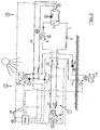
- the directly evaporating geothermal heat pump has a refrigerant circuit 1, a heat source circuit 2 and a heat distribution circuit 3, all of which are coupled to each other in terms of equipment.
- the refrigerant circuit 1 consists essentially of a first evaporating heat exchanger 4, a liquefying heat exchanger 5 and a recessed in the ground second and also evaporating Geoleyer 6, all of which are integrated via a refrigerant line 7 in a closed circuit.
- a refrigerant line 7 in a closed circuit.
- a generally electrically operated compressor unit 8 In the flow direction behind the first evaporating heat exchanger 4 is a generally electrically operated compressor unit 8 and in the same flow direction behind the liquefying heat exchanger 5, an expansion valve 9 is arranged.
- the temperature laxative side of the liquefying heat exchanger 5 is integrated into the heat distribution circuit 3, which is also designed as a closed circuit and from the liquefying heat exchanger 5 via a distribution line 10 to a heat consumer 11 back and forth.
- the heat consumer 11 may be a radiator, a heat storage or a withdrawal point.
- the temperature input side of the evaporating heat exchanger 4 is incorporated into the heat source circuit 2.
- This heat source circuit 2 is operated with a frost-proof liquid and initially consists of an external air heat cycle 12.
- To this outdoor air circulation circuit 12 includes an air heat exchanger 13 which is supplied via a preferably electrically driven fan 14 with an air flow and which is connected in a closed circuit via an air heat pipe 15 to the first evaporating heat exchanger 4 of the refrigerant circuit 1.
- an air heat exchanger 13 Before entering the temperature side of the first evaporating heat exchanger 4 is a in the direction of the first evaporating heat exchanger 4 promotional feed pump 16 is used, which is operated by an electric motor and which constantly circulates the water.
- Behind the temperature-input side of the first evaporating heat exchanger 4 is a switchable three-way valve 17, via which the outside air circuit 12 is connected to a solar heating circuit 18.
- This solar thermal circuit 18 includes a solar thermal line 19, which leads back from the first evaporating heat exchanger 4 via the three-way valve 17 and a feed pump 20 to a solar heat exchanger 21 and from there via another three-way valve 22 to the first evaporating heat exchanger 4.
- the outside air heat circuit 12 and the solar heating circuit 18 are arranged parallel to each other and connected to each other in such a way that is determined via the three-way valve 17, whether one of the two heat circuits 12, 18 or both are connected to the first evaporating heat exchanger 4.
- an excess heat pipe 23 branches off, which connects the solar thermal circuit 18 directly to the heat consumer 11 of the heat distribution circuit 3 in a closed excess heat circuit 24.
- the excess heat pipe 23 opens into the solar thermal circuit 18 on the one hand in the three-way valve 22 and on the other hand in the flow direction before the feed pump 20.
- the solar heat cycle 18 can be connected via a heat exchanger also indirectly with the heat distribution circuit 3.
- an energy management module 25 is provided, which is the input side via four lines 26, each with an outdoor purelylufttemperaturtler 27, with a Geotemperaturtler 28, connected to a solar temperature sensor 29 and a heat consumption sensor 30 in the heat distribution circuit 3.
- the energy management module 25 has on the input side, a line 31, which leads to a temperature sensor 32 in the incoming Lucasmérmiteitung 15 and a temperature sensor 33 in the returning air heat pipe 15.
- Another control line 43 connects the input of the energy management module 25 with a temperature or pressure sensor 44, which is located in the refrigerant circuit 1 in the flow direction in front of the compressor unit 8.
- the energy management module 25 is connected via a first control line 34 to the first three-way valve 17 in the air heat pipe 15 and via a second control line 35 to the feed pump 20 in the solar heat pipe 19.
- a third control line 36 connects the energy management module 25 with the second three-way valve 22 in the solar heat pipe 19.
- the feed pump 16 in the air heat circuit 12 performs a fourth control line 37th
- the directly evaporating air heat pump after the Fig. 2 differs from the directly evaporating geothermal heat pump after the Fig. 1 essentially in that, instead of the geoheat circuit, the air heat circuit is integrated directly into the refrigerant circuit 1.
- the directly evaporating air heat pump after the Fig. 2 therefore, it also has a refrigerant circuit 1, a heat source circuit 2 and a heat distribution circuit 3, which are all coupled together device technology.
- the refrigerant circuit 1 consists of the first evaporating heat exchanger 4, the liquefying heat exchanger 5 and a second evaporating and installed outside air heat exchanger 38, which are all involved via a refrigerant line 7 in a closed circuit.
- the temperature laxative side of the liquefying heat exchanger 5 is again involved in the heat distribution circuit 3.
- the temperature input side of the first evaporating heat exchanger 4 is incorporated into the heat source circuit 2.
- This heat source circuit 2 initially consists of the solar heating circuit 18, as well as in the geothermal heat pump after Fig. 1 is used, and a Geohärmeniklauf 39.
- To this geothermal circuit 39 includes a Geoleyer 40, which is connected in a closed circuit via a Geogrotechnisch 41 with the first evaporating heat exchanger 4 of the refrigerant circuit 1.
- promotional pump 42 is used.
- the returning Geotudetechnisch 41 opens into the three-way valve 17 of the solar thermal circuit 18th
- the directly evaporating heat pump is either geoographer according to the Fig. 1 or operated with outside air heat, like the Fig. 2 shows. Since both types of heat pump have the same function, only the function of the directly evaporating geothermal heat pump is based on the Fig. 1 described.
- the two feed pumps 16, 20 of the air heat circuit 12 and the solar heating circuit 18 are turned off, so that the heat pump is initially operated solely with the geothermal heat.
- the compressor unit 8 generates a flow within the refrigerant circuit 1. This flow flows through the soil located in the second evaporating Geoebenleyer 6, where it receives the existing geothermal heat there and then transported to the compressor unit 8.
- the refrigerant is then compressed in the compressor unit 8 so much that the temperature of the Increased refrigerant to a usable temperature.
- this elevated temperature is delivered to the heat distribution circuit 3 and forwarded there to the heat consumer 11.
- the energy management module 25 switches the higher tempered or more economical heat source circuit 2, which is usually the air thermal circuit 12 .
- the feed pump 16 and the fan 14 of the air heat circuit 12 turn on, whereby the warmer outside air is transmitted via the air heat exchanger 13 to the water cycle and transported to the first evaporating heat exchanger 4.
- the solar thermal circuit 18 is shut off by a corresponding position of the three-way valve 17.
- the outside air heat is then indirectly coupled into the refrigerant circuit 1.
- the solar thermal circuit 18 is used instead of the outside air heat circuit 12, it may be that the solar heat has a temperature that exceeds the optimal for a heat pump operation temperature, for example, 20 ° C. Then, the three-way valve 22 is switched so that the excess heat is supplied to the excess heat cycle 23. In this case, the feed of the usable amount of solar heat in the first evaporating heat exchanger 4 via the rotational speed of the feed pump 20 or via a pulse operation of the feed pump in the solar thermal circuit 18th
- the combined action of the directly evaporating geothermal circuit and the indirectly evaporating air thermal circuit or the indirectly evaporating solar thermal circuit 18 reduces the difference between the temperature provided and the temperature required for economical heat pump operation.
- the heat pump after the Fig. 3 differs from the heat pump after the Fig. 1 and 2 merely in that within the refrigerant circuit 1 no longer a common expansion valve for both evaporating heat exchangers 4, 38 is used. Rather, located in the refrigerant line 7 in the flow direction in front of the second evaporating heat exchanger 38 for a heat source a power controlled expansion valve 45 with an associated controllable check valve 46.
- the first evaporating heat exchanger 4 of the other two heat source circuits 18, 39 via an input line 47 with the liquid side of the refrigerant circuit 1 and connected via an output line 48 to the steaming side of the refrigerant circuit 1.
- an expansion valve 49 is provided, which is performed in accordance with the expansion valve 45 before the evaporating air heat exchanger 38 controlled by power.
- This expansion valve 49 is preceded by a controllable check valve 50.
- the heat pump after the Fig. 4 differs from the heat pump after the Fig. 3 essentially by the use of a controllable four-way mixer 51.
- This controllable four-way mixer 51 is located in front of the temperature-input side of the first and indirectly evaporating heat exchanger 4 and connects the geoheater circuit 39 with the solar thermal circuit 18 or mixes the flow rates of Geothermal circuit 39 and solar thermal circuit 18 with each other. In this way, the geothermal circuit 39 and the solar heating circuit 18 are connected to each other in such a way that it is determined via the four-way mixer 51, whether one of the two heat circuits 39, 18 or both are connected to the first evaporating heat exchanger 4 of the heat pump.
- controllable four-way mixer 51 is formed in a special way.
- the geoheater circuit 39 and the solar thermal circuit 18 are separated, so that only the geothermal circuit 39 is connected to the second evaporating heat exchanger 4, while the solar thermal circuit 18 merely circulates, sends excess energy directly to another heat consumer or is switched off.
- the geoheater circuit 39 and the solar heating circuit 18 are connected in series and thus combined to form a common heat circuit 39, 18, which then via the solar heat exchanger 21 and again via the four-way mixer 51 leads to the first evaporating heat exchanger 4.
- the four-way mixer 51 switches the geoheat circuit 39 and the solar heating circuit 18 parallel to each other and mixes them to a first partial flow leading to the first evaporating heat exchanger 4 and to a second partial flow leading to the solar heat exchanger 21.
Landscapes
- Engineering & Computer Science (AREA)
- Physics & Mathematics (AREA)
- Mechanical Engineering (AREA)
- Thermal Sciences (AREA)
- General Engineering & Computer Science (AREA)
- Chemical & Material Sciences (AREA)
- Combustion & Propulsion (AREA)
- Heat-Pump Type And Storage Water Heaters (AREA)
Claims (17)
- Pompe à chaleur, composée d'un circuit de réfrigérant (1), d'un circuit de répartiteur de chaleur (3) et d'un circuit de sources de chaleur (2) avec plus d'une source de chaleur, le circuit de réfrigérant (1) possédant au moins deux échangeurs de chaleur (4, 6, 38) à évaporation, caractérisée en ce qu'une vanne de détente (45, 49) séparée est affectée respectivement à chaque échangeur de chaleur (4, 6, 38) à évaporation et en ce que, pour la régulation de la température du réfrigérant en amont de l'unité de compresseur (8), la capacité de refoulement d'au moins une des vannes de détente (45, 49) peut être réglée.
- Pompe à chaleur selon la revendication 1,
caractérisée en ce qu'un échangeur de chaleur (6, 38) à évaporation raccorde directement une des sources de chaleur (12, 39) au circuit de réfrigérant (1) et en ce que le ou les autres échangeurs de chaleur (4) à évaporation raccorde/raccordent indirectement les sources de chaleur (12, 18, 39) restantes au circuit de réfrigérant (1). - Pompe à chaleur selon la revendication 2,
caractérisée en ce que les circuits de sources de chaleur (12,18, 39) restants peuvent être couplés en commun ou individuellement dans le circuit de réfrigérant (1). - Pompe à chaleur selon la revendication 3,
caractérisée en ce qu'au moins un circuit de sources de chaleur (12, 18, 39) restant possède une température plus élevée par rapport à la température d'entrée optimale sur le circuit de réfrigérant (1). - Pompe à chaleur selon la revendication 4,
caractérisée en ce que le circuit de sources de chaleur (18) restant avec la température la plus élevée est un circuit de chaleur solaire. - Pompe à chaleur selon la revendication 4,
caractérisée en ce que le circuit de sources de chaleur restant avec la température la plus élevée (18) peut être raccordé à un circuit d'excédent de chaleur (24) qui est raccordé directement au circuit de répartiteur de chaleur (3) ou à un consommateur externe pour l'évacuation de l'excédent de chaleur. - Pompe à chaleur selon la revendication 6,
caractérisée en ce que le circuit de sources de chaleur restant avec la température la plus élevée (18) possède une pompe d'alimentation qui est conçue pour un fonctionnement régulé et/ou pulsé en vue de l'alimentation de la chaleur solaire dans le circuit de réfrigérant (1). - Pompe à chaleur selon la revendication 4,
caractérisée en ce qu'au moins deux circuits sources de chaleur (12, 18, 39) sont affectés au premier échangeur de chaleur (4) à évaporation et en ce qu'un mélangeur d'écoulement commandé est situé en amont de l'échangeur de chaleur (4) à évaporation et est parcouru par les circuits de chaleur (12, 18, 39). - Pompe à chaleur selon la revendication 8,
caractérisée en ce que le mélangeur d'écoulement commandé est constitué de telle sorte qu'il fait passer les circuits de chaleur (13, 14) les uns à côté des autres, les raccorde les uns aux autres en série ou les mélange les uns avec les autres. - Pompe à chaleur selon la revendication 9,
caractérisée en ce que le mélangeur d'écoulement commandé est constitué de telle sorte que, dans la position de mélange, il divise les flux de liquide des circuits de chaleur en respectivement deux flux partiels, les premiers flux partiels respectifs formant un nouveau flux de liquide qui est guidé vers le premier échangeur de chaleur (4) à évaporation, et les deuxièmes flux partiels respectifs formant un nouveau flux de liquide qui sont renvoyés vers l'échangeur de chaleur (21) tempéré de façon plus élevée. - Pompe à chaleur selon la revendication 10,
caractérisée en ce que le mélangeur d'écoulement commandé est un mélangeur 4 voies (51). - Pompe à chaleur selon la revendication 11,
caractérisée en ce que la fonction du mélangeur d'écoulement commandé est déterminée par la température actuelle d'entrée de sources qui est mesurée par une sonde de température qui est située en amont du premier échangeur de chaleur (4) à évaporation. - Pompe à chaleur selon la revendication 12,
caractérisée en ce que, en amont du mélangeur d'écoulement, il est prévu une conduite de contournement (52) qui contourne le mélangeur d'écoulement commandé et dans laquelle est située une soupape de trop-plein (53) régulée en pression. - Procédé de régulation de la température d'entrée de sources sur une pompe à chaleur, composée d'un circuit de réfrigérant (1), d'un circuit de répartiteur de chaleur (3) et d'un circuit de sources de chaleur (2) avec plus d'une source de chaleur, qui fonctionne avec au moins deux circuits de chaleur (18, 39) disposés en parallèle et présentant deux températures différentes, caractérisé en ce que les au moins deux circuits de chaleur (18, 39) sont réunis en amont d'un échangeur de chaleur (4) à évaporation et sont mélangés selon la quantité à des fins d'équilibrage de température, et le circuit de réfrigérant (1) possède au moins deux échangeurs de chaleur (4, 6, 38) à évaporation, une vanne de détente (45, 49) séparée étant affectée respectivement à chaque échangeur de chaleur (4, 6, 38) à évaporation, et la capacité de refoulement d'au moins une des vannes de détente (45, 9) pouvant être réglée pour la régulation de la température du réfrigérant en amont de l'unité de compresseur (8).
- Procédé selon la revendication 14,
caractérisé en ce que chacun des flux de liquide des au moins deux circuits de chaleur (18, 39) est réparti en deux flux partiels et chaque premier flux partiel de chaque flux de liquide est conduit à un premier nouveau flux de liquide et chaque deuxième flux partiel de chaque flux de liquide est conduit à un deuxième nouveau flux de liquide, cela de façon conjointe, le premier des nouveaux flux de liquide étant conduit à travers l'échangeur de chaleur (4) à évaporation. - Procédé selon la revendication 15,
caractérisé en ce que le rapport de quantité des respectivement premiers flux partiels qui sont conduits conjointement au premier nouveau flux partiel et à l'échangeur de chaleur (4) à évaporation est déterminé d'une part par les rapports de température entre la température d'entrée de sources mesurée et la température d'entrée de sources optimale sur l'échangeur de chaleur (4) à évaporation et est déterminé d'autre part par les offres de température des deux flux de liquide. - Procédé selon la revendication 14, un des deux circuits de chaleur (18, 39) étant un circuit de chaleur solaire (18),
caractérisé en ce que l'énergie solaire est introduite sans stockage intermédiaire directement dans l'échangeur de chaleur (4) à évaporation de la pompe à chaleur.
Priority Applications (1)
| Application Number | Priority Date | Filing Date | Title |
|---|---|---|---|
| EP09168179.1A EP2287547B1 (fr) | 2009-08-19 | 2009-08-19 | Pompe à chaleur et procédé de réglage de la température d'entrée de sources sur une pompe à chaleur |
Applications Claiming Priority (1)
| Application Number | Priority Date | Filing Date | Title |
|---|---|---|---|
| EP09168179.1A EP2287547B1 (fr) | 2009-08-19 | 2009-08-19 | Pompe à chaleur et procédé de réglage de la température d'entrée de sources sur une pompe à chaleur |
Publications (2)
| Publication Number | Publication Date |
|---|---|
| EP2287547A1 EP2287547A1 (fr) | 2011-02-23 |
| EP2287547B1 true EP2287547B1 (fr) | 2016-03-16 |
Family
ID=41508895
Family Applications (1)
| Application Number | Title | Priority Date | Filing Date |
|---|---|---|---|
| EP09168179.1A Active EP2287547B1 (fr) | 2009-08-19 | 2009-08-19 | Pompe à chaleur et procédé de réglage de la température d'entrée de sources sur une pompe à chaleur |
Country Status (1)
| Country | Link |
|---|---|
| EP (1) | EP2287547B1 (fr) |
Families Citing this family (5)
| Publication number | Priority date | Publication date | Assignee | Title |
|---|---|---|---|---|
| KR20120136794A (ko) * | 2011-06-10 | 2012-12-20 | 삼성전자주식회사 | 히트펌프장치 및 히트펌프장치의 제어방법 |
| WO2014054178A1 (fr) | 2012-10-05 | 2014-04-10 | 三菱電機株式会社 | Dispositif de pompe à chaleur |
| DE202017105111U1 (de) * | 2017-08-25 | 2017-09-08 | ATF Anwendungszentrum für Technik und Forschung UG (haftungsbeschränkt) | Wärmegewinnungsanlage und Wärmetauschereinheit |
| JP7474987B2 (ja) | 2020-08-18 | 2024-04-26 | ゼネラルヒートポンプ工業株式会社 | ヒートポンプシステム |
| CN115231717B (zh) * | 2022-08-26 | 2023-12-19 | 镇江新区固废处置股份有限公司 | 一种基于evair技术的高含盐有机废水处理系统及工艺 |
Family Cites Families (14)
| Publication number | Priority date | Publication date | Assignee | Title |
|---|---|---|---|---|
| DE2128331A1 (de) * | 1971-06-08 | 1973-01-04 | Ctc Gmbh | In einem fussboden, einer wand oder einer decke zu verlegender rohrstrang |
| DE2161495A1 (de) * | 1971-12-10 | 1973-06-20 | Rhein Westfael Elect Werk Ag | Waermerueckgewinnungsanlage |
| US4065938A (en) * | 1976-01-05 | 1978-01-03 | Sun-Econ, Inc. | Air-conditioning apparatus with booster heat exchanger |
| FR2380502A1 (fr) * | 1977-02-14 | 1978-09-08 | Bontemps Francine | Pompe thermodynamique a double evaporateurs air-eau pour chauffage solaire |
| FR2485169B1 (fr) * | 1980-06-20 | 1986-01-03 | Electricite De France | Perfectionnements aux installations de fourniture d'eau chaude comprenant un circuit thermodynamique |
| US5461876A (en) | 1994-06-29 | 1995-10-31 | Dressler; William E. | Combined ambient-air and earth exchange heat pump system |
| EP1248055A3 (fr) * | 2001-03-26 | 2004-03-31 | Vaillant GmbH | Source de chaleur ambiante totale pour une pompe à chaleur |
| DE102005011700B4 (de) * | 2005-03-11 | 2019-12-24 | Stiebel Eltron Gmbh & Co. Kg | Wärmepumpensystem |
| US7228696B2 (en) | 2005-06-27 | 2007-06-12 | Geofurnace Development Inc. | Hybrid heating and cooling system |
| US8733429B2 (en) * | 2006-02-13 | 2014-05-27 | The H.L. Turner Group, Inc. | Hybrid heating and/or cooling system |
| JP2009540258A (ja) * | 2006-06-07 | 2009-11-19 | ウォーターズ ホット,インコーポレーテッド | バイオ再生可能熱エネルギー加熱冷却システム及び方法 |
| DE202007013888U1 (de) | 2007-10-04 | 2007-12-13 | Kroll, Jürgen | Terra Solarmodul |
| DE102007048909A1 (de) * | 2007-10-05 | 2009-04-09 | Technische Universität Dresden | Wärmepumpenanordnung |
| DE202008000374U1 (de) * | 2008-01-10 | 2009-05-20 | Karow, Steffen | Wärmepumpe |
-
2009
- 2009-08-19 EP EP09168179.1A patent/EP2287547B1/fr active Active
Also Published As
| Publication number | Publication date |
|---|---|
| EP2287547A1 (fr) | 2011-02-23 |
Similar Documents
| Publication | Publication Date | Title |
|---|---|---|
| DE102009004501B4 (de) | Wärmepumpe und Verfahren zur Regelung der Quelleneingangstemperatur an der Wärmepumpe | |
| DE102007050446B4 (de) | Indirekt verdampfende Wärmepumpe und Verfahren zur Optimierung der Eingangstemperatur der indirekt verdampfenden Wärmepumpe | |
| EP2363650B1 (fr) | Groupe de production de chaleur doté d'un réglage de pompes à jet | |
| EP2287547B1 (fr) | Pompe à chaleur et procédé de réglage de la température d'entrée de sources sur une pompe à chaleur | |
| EP2154436A2 (fr) | Procédé et dispositif de consommation de chaleur | |
| EP2375175A2 (fr) | Dispositif destiné à l'alimentation en chaleur de bâtiments | |
| EP0099501B1 (fr) | Méthode pour changer la production d'énergie électrique d'une centrale de chauffe sans influencer la livraison de chaleur aux consommateurs de chaleur | |
| DE102013005035A1 (de) | Verfahren und Vorrichtung zur Einkopplung von Wärme aus einem Nahwärmenetz | |
| WO2018172107A1 (fr) | Centrale électrique servant à produire une énergie électrique et procédé servant à faire fonctionner une centrale électrique | |
| WO2006024065A1 (fr) | Dispositif pour fournir de la chaleur a au moins un recepteur et evacuer de la chaleur de ce recepteur | |
| DE102007063009B4 (de) | Verfahren zur Belüftung von Objekten und Vorrichtung zur Belüftung von Objekten, insbesondere raumlufttechnische Anlage | |
| EP2458304A2 (fr) | Installation de pompe à chaleur comprenant une pompe à chaleur et procédé de fonctionnement d'une telle installation de pompe à chaleur | |
| DE2846797A1 (de) | Vorrichtung zur waermerueckgewinnung | |
| DE2916530A1 (de) | Verfahren und einrichtung zur erzeugung und verteilung thermischer energie mit kompensationsverlagerung in geothermische schichten | |
| EP1980804A2 (fr) | Procédé de préparation d'énergie thermique | |
| DE102014000671B4 (de) | Solaranlage und Verfahren zum Betreiben einer solchen | |
| WO2010094282A2 (fr) | Installation de chauffage et de refroidissement et procédé pour faire fonctionner une installation de chauffage et de refroidissement | |
| DE202008000374U1 (de) | Wärmepumpe | |
| DE102008020637A1 (de) | Warmwasserversorgungsanlage mit einem Warmwasserspeicher | |
| WO1982001237A1 (fr) | Systeme a vapeur a distance avec retour commun des condensats et procede pour le refoulement des condensats | |
| EP3460340B1 (fr) | Procédé de fourniture de chaleur, installation de récupération de chaleur et unité de fourniture de chaleur | |
| DE102007062342B4 (de) | Verfahren und Anordnung zur Erhöhung des Temperaturniveaus im Kreislauf solarthermischer Anlagen oder Blockheizkraftwerke | |
| EP1845313A1 (fr) | Appareil à accumulation de chaleur | |
| DE102010051868A1 (de) | Wärmepumpenanlage, insbesondere zur Klimatisierung eines Gebäudes | |
| DE202016103592U1 (de) | System umfassend zumindest einen Wärmespeicher |
Legal Events
| Date | Code | Title | Description |
|---|---|---|---|
| PUAI | Public reference made under article 153(3) epc to a published international application that has entered the european phase |
Free format text: ORIGINAL CODE: 0009012 |
|
| AK | Designated contracting states |
Kind code of ref document: A1 Designated state(s): AT BE BG CH CY CZ DE DK EE ES FI FR GB GR HR HU IE IS IT LI LT LU LV MC MK MT NL NO PL PT RO SE SI SK SM TR |
|
| AX | Request for extension of the european patent |
Extension state: AL BA RS |
|
| 17P | Request for examination filed |
Effective date: 20110810 |
|
| 17Q | First examination report despatched |
Effective date: 20150302 |
|
| GRAP | Despatch of communication of intention to grant a patent |
Free format text: ORIGINAL CODE: EPIDOSNIGR1 |
|
| INTG | Intention to grant announced |
Effective date: 20151023 |
|
| GRAS | Grant fee paid |
Free format text: ORIGINAL CODE: EPIDOSNIGR3 |
|
| GRAA | (expected) grant |
Free format text: ORIGINAL CODE: 0009210 |
|
| AK | Designated contracting states |
Kind code of ref document: B1 Designated state(s): AT BE BG CH CY CZ DE DK EE ES FI FR GB GR HR HU IE IS IT LI LT LU LV MC MK MT NL NO PL PT RO SE SI SK SM TR |
|
| REG | Reference to a national code |
Ref country code: GB Ref legal event code: FG4D Free format text: NOT ENGLISH |
|
| REG | Reference to a national code |
Ref country code: CH Ref legal event code: EP |
|
| REG | Reference to a national code |
Ref country code: IE Ref legal event code: FG4D Free format text: LANGUAGE OF EP DOCUMENT: GERMAN |
|
| REG | Reference to a national code |
Ref country code: AT Ref legal event code: REF Ref document number: 781589 Country of ref document: AT Kind code of ref document: T Effective date: 20160415 |
|
| REG | Reference to a national code |
Ref country code: DE Ref legal event code: R096 Ref document number: 502009012235 Country of ref document: DE |
|
| REG | Reference to a national code |
Ref country code: CH Ref legal event code: NV Representative=s name: ISLER AND PEDRAZZINI AG, CH |
|
| REG | Reference to a national code |
Ref country code: NL Ref legal event code: MP Effective date: 20160316 |
|
| REG | Reference to a national code |
Ref country code: LT Ref legal event code: MG4D |
|
| PG25 | Lapsed in a contracting state [announced via postgrant information from national office to epo] |
Ref country code: HR Free format text: LAPSE BECAUSE OF FAILURE TO SUBMIT A TRANSLATION OF THE DESCRIPTION OR TO PAY THE FEE WITHIN THE PRESCRIBED TIME-LIMIT Effective date: 20160316 Ref country code: GR Free format text: LAPSE BECAUSE OF FAILURE TO SUBMIT A TRANSLATION OF THE DESCRIPTION OR TO PAY THE FEE WITHIN THE PRESCRIBED TIME-LIMIT Effective date: 20160617 Ref country code: NO Free format text: LAPSE BECAUSE OF FAILURE TO SUBMIT A TRANSLATION OF THE DESCRIPTION OR TO PAY THE FEE WITHIN THE PRESCRIBED TIME-LIMIT Effective date: 20160616 Ref country code: FI Free format text: LAPSE BECAUSE OF FAILURE TO SUBMIT A TRANSLATION OF THE DESCRIPTION OR TO PAY THE FEE WITHIN THE PRESCRIBED TIME-LIMIT Effective date: 20160316 |
|
| PG25 | Lapsed in a contracting state [announced via postgrant information from national office to epo] |
Ref country code: SE Free format text: LAPSE BECAUSE OF FAILURE TO SUBMIT A TRANSLATION OF THE DESCRIPTION OR TO PAY THE FEE WITHIN THE PRESCRIBED TIME-LIMIT Effective date: 20160316 Ref country code: NL Free format text: LAPSE BECAUSE OF FAILURE TO SUBMIT A TRANSLATION OF THE DESCRIPTION OR TO PAY THE FEE WITHIN THE PRESCRIBED TIME-LIMIT Effective date: 20160316 Ref country code: LT Free format text: LAPSE BECAUSE OF FAILURE TO SUBMIT A TRANSLATION OF THE DESCRIPTION OR TO PAY THE FEE WITHIN THE PRESCRIBED TIME-LIMIT Effective date: 20160316 Ref country code: LV Free format text: LAPSE BECAUSE OF FAILURE TO SUBMIT A TRANSLATION OF THE DESCRIPTION OR TO PAY THE FEE WITHIN THE PRESCRIBED TIME-LIMIT Effective date: 20160316 |
|
| PG25 | Lapsed in a contracting state [announced via postgrant information from national office to epo] |
Ref country code: IS Free format text: LAPSE BECAUSE OF FAILURE TO SUBMIT A TRANSLATION OF THE DESCRIPTION OR TO PAY THE FEE WITHIN THE PRESCRIBED TIME-LIMIT Effective date: 20160716 Ref country code: PL Free format text: LAPSE BECAUSE OF FAILURE TO SUBMIT A TRANSLATION OF THE DESCRIPTION OR TO PAY THE FEE WITHIN THE PRESCRIBED TIME-LIMIT Effective date: 20160316 Ref country code: EE Free format text: LAPSE BECAUSE OF FAILURE TO SUBMIT A TRANSLATION OF THE DESCRIPTION OR TO PAY THE FEE WITHIN THE PRESCRIBED TIME-LIMIT Effective date: 20160316 |
|
| PG25 | Lapsed in a contracting state [announced via postgrant information from national office to epo] |
Ref country code: SK Free format text: LAPSE BECAUSE OF FAILURE TO SUBMIT A TRANSLATION OF THE DESCRIPTION OR TO PAY THE FEE WITHIN THE PRESCRIBED TIME-LIMIT Effective date: 20160316 Ref country code: PT Free format text: LAPSE BECAUSE OF FAILURE TO SUBMIT A TRANSLATION OF THE DESCRIPTION OR TO PAY THE FEE WITHIN THE PRESCRIBED TIME-LIMIT Effective date: 20160718 Ref country code: CZ Free format text: LAPSE BECAUSE OF FAILURE TO SUBMIT A TRANSLATION OF THE DESCRIPTION OR TO PAY THE FEE WITHIN THE PRESCRIBED TIME-LIMIT Effective date: 20160316 Ref country code: RO Free format text: LAPSE BECAUSE OF FAILURE TO SUBMIT A TRANSLATION OF THE DESCRIPTION OR TO PAY THE FEE WITHIN THE PRESCRIBED TIME-LIMIT Effective date: 20160316 Ref country code: SM Free format text: LAPSE BECAUSE OF FAILURE TO SUBMIT A TRANSLATION OF THE DESCRIPTION OR TO PAY THE FEE WITHIN THE PRESCRIBED TIME-LIMIT Effective date: 20160316 Ref country code: ES Free format text: LAPSE BECAUSE OF FAILURE TO SUBMIT A TRANSLATION OF THE DESCRIPTION OR TO PAY THE FEE WITHIN THE PRESCRIBED TIME-LIMIT Effective date: 20160316 |
|
| REG | Reference to a national code |
Ref country code: DE Ref legal event code: R097 Ref document number: 502009012235 Country of ref document: DE |
|
| PG25 | Lapsed in a contracting state [announced via postgrant information from national office to epo] |
Ref country code: IT Free format text: LAPSE BECAUSE OF FAILURE TO SUBMIT A TRANSLATION OF THE DESCRIPTION OR TO PAY THE FEE WITHIN THE PRESCRIBED TIME-LIMIT Effective date: 20160316 Ref country code: BE Free format text: LAPSE BECAUSE OF NON-PAYMENT OF DUE FEES Effective date: 20160831 |
|
| PLBE | No opposition filed within time limit |
Free format text: ORIGINAL CODE: 0009261 |
|
| STAA | Information on the status of an ep patent application or granted ep patent |
Free format text: STATUS: NO OPPOSITION FILED WITHIN TIME LIMIT |
|
| PG25 | Lapsed in a contracting state [announced via postgrant information from national office to epo] |
Ref country code: DK Free format text: LAPSE BECAUSE OF FAILURE TO SUBMIT A TRANSLATION OF THE DESCRIPTION OR TO PAY THE FEE WITHIN THE PRESCRIBED TIME-LIMIT Effective date: 20160316 |
|
| 26N | No opposition filed |
Effective date: 20161219 |
|
| PG25 | Lapsed in a contracting state [announced via postgrant information from national office to epo] |
Ref country code: BG Free format text: LAPSE BECAUSE OF FAILURE TO SUBMIT A TRANSLATION OF THE DESCRIPTION OR TO PAY THE FEE WITHIN THE PRESCRIBED TIME-LIMIT Effective date: 20160616 |
|
| PG25 | Lapsed in a contracting state [announced via postgrant information from national office to epo] |
Ref country code: MC Free format text: LAPSE BECAUSE OF FAILURE TO SUBMIT A TRANSLATION OF THE DESCRIPTION OR TO PAY THE FEE WITHIN THE PRESCRIBED TIME-LIMIT Effective date: 20160316 |
|
| GBPC | Gb: european patent ceased through non-payment of renewal fee |
Effective date: 20160819 |
|
| REG | Reference to a national code |
Ref country code: FR Ref legal event code: ST Effective date: 20170428 |
|
| PG25 | Lapsed in a contracting state [announced via postgrant information from national office to epo] |
Ref country code: SI Free format text: LAPSE BECAUSE OF FAILURE TO SUBMIT A TRANSLATION OF THE DESCRIPTION OR TO PAY THE FEE WITHIN THE PRESCRIBED TIME-LIMIT Effective date: 20160316 |
|
| REG | Reference to a national code |
Ref country code: IE Ref legal event code: MM4A |
|
| PG25 | Lapsed in a contracting state [announced via postgrant information from national office to epo] |
Ref country code: FR Free format text: LAPSE BECAUSE OF NON-PAYMENT OF DUE FEES Effective date: 20160831 Ref country code: GB Free format text: LAPSE BECAUSE OF NON-PAYMENT OF DUE FEES Effective date: 20160819 Ref country code: IE Free format text: LAPSE BECAUSE OF NON-PAYMENT OF DUE FEES Effective date: 20160819 |
|
| PG25 | Lapsed in a contracting state [announced via postgrant information from national office to epo] |
Ref country code: LU Free format text: LAPSE BECAUSE OF NON-PAYMENT OF DUE FEES Effective date: 20160819 |
|
| PG25 | Lapsed in a contracting state [announced via postgrant information from national office to epo] |
Ref country code: CY Free format text: LAPSE BECAUSE OF FAILURE TO SUBMIT A TRANSLATION OF THE DESCRIPTION OR TO PAY THE FEE WITHIN THE PRESCRIBED TIME-LIMIT Effective date: 20160316 Ref country code: HU Free format text: LAPSE BECAUSE OF FAILURE TO SUBMIT A TRANSLATION OF THE DESCRIPTION OR TO PAY THE FEE WITHIN THE PRESCRIBED TIME-LIMIT; INVALID AB INITIO Effective date: 20090819 |
|
| PG25 | Lapsed in a contracting state [announced via postgrant information from national office to epo] |
Ref country code: MT Free format text: LAPSE BECAUSE OF FAILURE TO SUBMIT A TRANSLATION OF THE DESCRIPTION OR TO PAY THE FEE WITHIN THE PRESCRIBED TIME-LIMIT Effective date: 20160316 Ref country code: MK Free format text: LAPSE BECAUSE OF FAILURE TO SUBMIT A TRANSLATION OF THE DESCRIPTION OR TO PAY THE FEE WITHIN THE PRESCRIBED TIME-LIMIT Effective date: 20160316 Ref country code: TR Free format text: LAPSE BECAUSE OF FAILURE TO SUBMIT A TRANSLATION OF THE DESCRIPTION OR TO PAY THE FEE WITHIN THE PRESCRIBED TIME-LIMIT Effective date: 20160316 |
|
| PGFP | Annual fee paid to national office [announced via postgrant information from national office to epo] |
Ref country code: CH Payment date: 20230902 Year of fee payment: 15 Ref country code: AT Payment date: 20230818 Year of fee payment: 15 |
|
| PGFP | Annual fee paid to national office [announced via postgrant information from national office to epo] |
Ref country code: DE Payment date: 20230829 Year of fee payment: 15 |