EP2287066B1 - Side trunk mounting structure for two-wheeled motor vehicle - Google Patents
Side trunk mounting structure for two-wheeled motor vehicle Download PDFInfo
- Publication number
- EP2287066B1 EP2287066B1 EP09808145A EP09808145A EP2287066B1 EP 2287066 B1 EP2287066 B1 EP 2287066B1 EP 09808145 A EP09808145 A EP 09808145A EP 09808145 A EP09808145 A EP 09808145A EP 2287066 B1 EP2287066 B1 EP 2287066B1
- Authority
- EP
- European Patent Office
- Prior art keywords
- side trunk
- rear fender
- vehicle body
- mounting holes
- pawls
- Prior art date
- Legal status (The legal status is an assumption and is not a legal conclusion. Google has not performed a legal analysis and makes no representation as to the accuracy of the status listed.)
- Not-in-force
Links
- 229920000049 Carbon (fiber) Polymers 0.000 claims description 5
- 239000004917 carbon fiber Substances 0.000 claims description 5
- 239000003365 glass fiber Substances 0.000 claims description 5
- 239000011347 resin Substances 0.000 claims description 5
- 229920005989 resin Polymers 0.000 claims description 5
- 238000005452 bending Methods 0.000 claims description 2
- 238000000034 method Methods 0.000 description 4
- 239000002828 fuel tank Substances 0.000 description 3
- 210000003127 knee Anatomy 0.000 description 3
- 230000002146 bilateral effect Effects 0.000 description 2
- 239000003054 catalyst Substances 0.000 description 2
- 230000001010 compromised effect Effects 0.000 description 2
- 230000003014 reinforcing effect Effects 0.000 description 2
- 229910000838 Al alloy Inorganic materials 0.000 description 1
- 229910000831 Steel Inorganic materials 0.000 description 1
- RTAQQCXQSZGOHL-UHFFFAOYSA-N Titanium Chemical compound [Ti] RTAQQCXQSZGOHL-UHFFFAOYSA-N 0.000 description 1
- 230000003292 diminished effect Effects 0.000 description 1
- 230000003467 diminishing effect Effects 0.000 description 1
- 230000000694 effects Effects 0.000 description 1
- 210000002414 leg Anatomy 0.000 description 1
- 239000007769 metal material Substances 0.000 description 1
- VNWKTOKETHGBQD-UHFFFAOYSA-N methane Chemical compound C VNWKTOKETHGBQD-UHFFFAOYSA-N 0.000 description 1
- 238000009877 rendering Methods 0.000 description 1
- 239000010959 steel Substances 0.000 description 1
- 239000013589 supplement Substances 0.000 description 1
- 239000010936 titanium Substances 0.000 description 1
- 229910052719 titanium Inorganic materials 0.000 description 1
Images






Classifications
-
- B—PERFORMING OPERATIONS; TRANSPORTING
- B62—LAND VEHICLES FOR TRAVELLING OTHERWISE THAN ON RAILS
- B62J—CYCLE SADDLES OR SEATS; AUXILIARY DEVICES OR ACCESSORIES SPECIALLY ADAPTED TO CYCLES AND NOT OTHERWISE PROVIDED FOR, e.g. ARTICLE CARRIERS OR CYCLE PROTECTORS
- B62J7/00—Luggage carriers
- B62J7/02—Luggage carriers characterised by the arrangement thereof on cycles
- B62J7/04—Luggage carriers characterised by the arrangement thereof on cycles arranged above or behind the rear wheel
-
- B—PERFORMING OPERATIONS; TRANSPORTING
- B62—LAND VEHICLES FOR TRAVELLING OTHERWISE THAN ON RAILS
- B62J—CYCLE SADDLES OR SEATS; AUXILIARY DEVICES OR ACCESSORIES SPECIALLY ADAPTED TO CYCLES AND NOT OTHERWISE PROVIDED FOR, e.g. ARTICLE CARRIERS OR CYCLE PROTECTORS
- B62J15/00—Mud-guards for wheels
-
- B—PERFORMING OPERATIONS; TRANSPORTING
- B62—LAND VEHICLES FOR TRAVELLING OTHERWISE THAN ON RAILS
- B62J—CYCLE SADDLES OR SEATS; AUXILIARY DEVICES OR ACCESSORIES SPECIALLY ADAPTED TO CYCLES AND NOT OTHERWISE PROVIDED FOR, e.g. ARTICLE CARRIERS OR CYCLE PROTECTORS
- B62J9/00—Containers specially adapted for cycles, e.g. panniers or saddle bags
- B62J9/20—Containers specially adapted for cycles, e.g. panniers or saddle bags attached to the cycle as accessories
- B62J9/23—Containers specially adapted for cycles, e.g. panniers or saddle bags attached to the cycle as accessories above or alongside the rear wheel
-
- B—PERFORMING OPERATIONS; TRANSPORTING
- B62—LAND VEHICLES FOR TRAVELLING OTHERWISE THAN ON RAILS
- B62J—CYCLE SADDLES OR SEATS; AUXILIARY DEVICES OR ACCESSORIES SPECIALLY ADAPTED TO CYCLES AND NOT OTHERWISE PROVIDED FOR, e.g. ARTICLE CARRIERS OR CYCLE PROTECTORS
- B62J9/00—Containers specially adapted for cycles, e.g. panniers or saddle bags
- B62J9/20—Containers specially adapted for cycles, e.g. panniers or saddle bags attached to the cycle as accessories
- B62J9/27—Containers specially adapted for cycles, e.g. panniers or saddle bags attached to the cycle as accessories characterised by mounting arrangements, e.g. quick release arrangements
Definitions
- the present invention relates to an improvement in a side trunk mounting structure for a two-wheeled motor vehicle.
- a side trunk mounting structure according to the preamble of claim 1 is known from US 5,025,883 A .
- the side trunk mounting structure disclosed in Patent Document 1 comprises a rear frame installed on a rear part of a vehicle body, and a trunk support part provided to the rear frame.
- the rear frame has first concave parts set apart from each other in a longitudinal direction, and a second concave part provided between the first concave parts.
- the trunk support part is configured from the first concave parts and the second concave part.
- the side trunk has a side trunk latching means, and is mounted to the rear frame by the side trunk latching means being latched onto the trunk support part.
- the rear frame is covered by a tail cover.
- the tail cover has a plurality of openings formed so as to match up with the positions of the first concave parts and the second concave part.
- An object of the present invention is to provide a side trunk mounting structure for a two-wheeled motor vehicle whereby the vehicle can have a more attractive external appearance when the side trunk has been mounted, without reducing the degree of freedom in frame designing.
- a side trunk mounting structure for a two-wheeled motor vehicle comprising: a rear frame disposed on a rear part of a vehicle body; a rear fender, provided below the rear frame, for covering a rear wheel; a rider's seat, provided above the rear fender, for allowing a rider to sit on; and a side trunk mounted to a side surface of the rear fender, wherein the rear fender has a plurality of side trunk mounting holes for mounting the side trunk, the side trunk has a plurality of pawls, extending inwardly of the vehicle body and bending downward, for hooking into the side trunk mounting holes, and a plurality of lower engaging arms, provided below the respective pawls and extending upwardly inwardly of the vehicle body, for holding the rear fender in cooperation with the pawls, and the side trunk is mounted to the rear fender by the rear fender being held between the pawls and the lower engaging arms.
- each of the side trunk mounting holes is provided below the rider's seat.
- the rear fender is formed from a resin containing glass fibers or carbon fibers.
- the rear fender has a plurality of downwardly extending hanging parts held by the lower engaging arms.
- the side trunk mounting structure further comprises at least front and rear fastening parts for fastening the rear fender to the vehicle body frame of the vehicle body, wherein at least one of the plurality of side trunk mounting holes is provided between the two front and rear fastening parts.
- the side trunk mounting structure for use in a two-wheeled motor vehicle has a latching arm mounted to a vehicle body frame of the vehicle body and extending from a co-rider's step holder, wherein the side trunk has a side surface facing the vehicle body frame and having an engaging concave part for engaging with the latching arm.
- Each of the pawls which hook into the individual side trunk mounting holes is provided with an elastic member.
- the plurality of side trunk mounting holes is provided to the rear fender, and the side trunk is mounted directly in the side trunk mounting holes provided to the rear fender.
- the side trunk is mounted in side trunk mounting holes formed in the top surface of the rear frame.
- the side trunk mounting holes are opened in the top surface of the rear frame, when the side trunk is removed, part of the rear frame can be seen through the side trunk mounting holes, and the external appearance of the vehicle is compromised. Additionally, the degree of freedom in the design of the frame is reduced by a commensurate amount relative to where the side trunk mounting holes are provided in the top surface of the rear frame.
- the side trunk mounting holes are provided below the rider's seat, they can be obscured from view when the vehicle is seen from above. If the side trunk mounting holes are obscured from view, the external appearance of the vehicle will not readily be affected even when the side trunk is removed, and the vehicle can have an even more attractive external appearance.
- the rigidity of the rear fender can be increased, and the load-bearing capacity can be increased.
- the saddlebag mounting strength can be increased.
- the saddlebag can, when in a mounted state, have a more attractive appearance.
- the pawls are provided with elastic members.
- the pawls are pressed into the rear fender with the elastic members disposed therebetween, and are made to adhere firmly to the saddlebag mounting portion of the rear fender, thereby making it unlikely that gaps will form between the pawls and the saddlebag mounting holes even when there is a change in the mounting relationship between the pawls and the saddlebag mounting holes.
- a two-wheeled motor vehicle 10 comprises a vehicle body frame 11 as shown in FIG. 1 .
- the vehicle body frame 11 is composed of a head pipe 12; a main frame 14 which extends rearward from the head pipe 12 and supports an engine 13; and a rear frame 19 for supporting a rider's seat 15 extending rearward from a top part of a rear end of the main frame 14, mounting a battery 16 and other electrical components and the like, and supporting a vehicle body rear part 18 including a rear fender 17.
- the main frame 14 includes a pivot plate 22 which is provided to the rear end part of the main frame 14 and which supports a swing arm 28.
- the pivot plate 22 has a pivot shaft 27.
- the rear swing arm (the swing arm) 28 extends rearward from the pivot shaft 27.
- a rear cushion unit 29 for absorbing impact is provided between the main frame 14 and the swing arm 28.
- a rear wheel 31 is mounted on a rear end of the swing arm 28. The rear wheel 31 is driven by a drive shaft (not shown) which links the engine 13 and the rear wheel 31 together.
- a front fork 24 is provided to the head pipe 12.
- a front wheel 25 is mounted on the bottom end part of the front fork 24.
- a steering handlebar 26 for steering the front wheel 25 is provided to the top end part of the front fork 24.
- the engine 13 is an engine having four cylinders arranged in a "V"-shaped configuration.
- the engine 13 is supported on the main frame 14 with first through fourth support points 30a to 30d disposed therebetween.
- the first through fourth support points 30a to 30d are provided horizontally along the vehicle width direction.
- the support points provided to the pivot plate 22 are the third and fourth support points 30c, 30d. In other words, the engine 13 is supported by the main frame 14 and the pivot plate 22.
- the V-shaped four-cylinder engine 13 has a crank case 37, a first cylinder 35 extending in a forward and upward direction relative to a crankshaft 34 provided to the crank case 37, and a second cylinder 36 extending in a rearward and upward direction relative to the crankshaft 34.
- the first cylinder 35 and the second cylinder 36 are formed into a V shape.
- the main frame 14 lies over the first cylinder 35 and the second cylinder 36, which constitute a top part of the engine 13.
- Part of the pivot plate 22 lies above the crank case 37, which constitutes a rear part of the engine 13.
- the V-shaped four-cylinder engine 13 is connected to an exhaust device 33.
- the exhaust device 33 is configured from exhaust pipes 41a to 41d extending from the cylinders 35, 35, 36, 36; a catalyst pipe 45 wherein the exhaust pipes 41a to 41d converge and the exhaust gas is cleaned; an overall assembly pipe 46 extending from the catalyst pipe 45; and a muffler 47 connected to the overall assembly pipe 46.
- a radiator unit 51 cools the engine 13.
- a front disk brake caliper 52 is provided to the front fork.
- a front disk plate 53 is held by the front disk brake caliper 52 provided to the front wheel 25.
- a front master cylinder 54 is provided to the steering handlebar 26.
- a fuel tank cover 56 covers a fuel tank mounted on the main frame 14 and also serves as a cowl 70.
- a driver step 57 is mounted on the main frame 14.
- a rider's step 58 is mounted on the rear frame 19.
- the reference numerals 59, 60, and 61 indicate a headlight, a front fender, and a mirror, respectively.
- the reference numerals 62 and 65 indicate a rear disk brake caliper and a main stand, respectively.
- a rear disk plate 63 is held by the rear disk brake caliper 62 provided to the rear wheel 31.
- cowl 70 constituting what is primarily the externally visible part of the two-wheeled motor vehicle 10.
- the cowl 70 comprises a front cowl 72 for covering the front of the vehicle body frame 11 via a cowl stay extending from the head pipe 12, a side cowl 73 which is provided as a continuation of the front cowl part 72 and which covers the side of the vehicle, and an under cowl 74 provided below the engine 13, it being an object to improve the external appearance of the windshield and the vehicle.
- the front cowl 72 includes an upper center cowl 76 for covering a top region of the headlight 59, a windscreen 77 extending above the upper center cowl 76, and part of a front upper side cowl 79 to which a middle cowl 78 covering the side of the main frame 14 is mounted, the front upper side cowl 79 supporting left and right sides of the windscreen 77.
- the side cowl 73 includes the front upper side cowl 79 for supporting the left and right sides of the windscreen 77; the middle cowl 78 for covering the head pipe 12 and the side of the main frame 14; a knee cover 81 for covering a bottom of the fuel tank cover 56 the knee cover being located between legs Rf of a driver R while the vehicle is driven, and a pivot plate cover 82 which is provided below the knee cover 81 and which covers the external surface of the pivot plate 22, which is a structural element of the main frame 14.
- the rear frame 19 is disposed on the rear part of the vehicle body, the rear fender 17 for covering the rear wheel 31 is provided below the rear frame 19, the rider's seat 15 on which the rider sits is provided above the rear fender 17, and side trunks 111L, 111R (see FIG. 9 ) in which items are stowed are mounted on the rear fender 17.
- the left and right side trunks 111L, 111R (only the nearer symbol 111L is shown) are provided in bilateral symmetry about a center line of the vehicle as shown in FIG. 9 . Since there is no significant difference between their structures, the left side trunk 111L will be described as a side trunk 111, and the right side trunk 111R will not be described.
- the rear fender 17 covering the top part of the rear wheel 31 is mounted on the rear frame 19 of the vehicle body frame 11 via front and rear fastening parts 112f, 112r, as shown in FIG. 2 .
- Two side trunk mounting holes 113f, 113r for mounting the side trunk 111 are provided to the front and rear of the rear fender 17 (see FIG. 8 ), and a plurality of ribs (hanging parts) 114 which engages part of the side trunk 111 extends toward the inside of the rear fender 17 between the side trunk mounting holes 113f, 113r.
- These ribs 114 have both a mounting function for mounting the side trunk and a reinforcing function for reinforcing the hanging parts.
- the side trunk mounting holes 113f, 113r and the plurality of ribs 114 will be described hereinafter.
- a tail light unit 116 including a stop light and rear turn signal lamps is provided to the rear part of the rider's seat 15 so as to jut outward to the left and right sides.
- a latch arm 117 extends rearward from the rider's step 58 and latches onto the side trunk 111, as shown in FIG. 8 .
- the reference numerals 121, 122, and 123 indicate a grab rail, a license bracket, and a rear cowl, respectively.
- two front and rear fastening parts 112f, 112r for fastening the rear fender 17 to the vehicle body frame 11, but three or more fastening parts may also be provided.
- Two front and rear side trunk mounting holes 113f, 113r are also provided, but three or more may be provided as well.
- the side trunk 111 has a case body 124 for storing items, a cover body 125 for covering the exterior of the case body 124, a handle 126 swingably provided to a top surface 124t of the case body 124 and used when attaching, removing, and carrying the side trunk 111, front and rear pawls 128f, 128r (see FIG. 13 ) which are provided to a side surface top part 124su of the case body 124 and which engage with the front and rear side trunk mounting holes 113f, 113r, and an engaging concave part 131 which is similarly provided to a side surface bottom part 124sb and which engages with a distal end of the latch arm 117, as shown in FIG. 3 .
- the side trunk 111 comprises pawls 128f, 128r which extend inward in the width direction of the vehicle body, curve downward, and hook into the side trunk mounting holes 113f, 113r.
- the handle 126 is held in the hand, the saddlebag 111 is brought to the rear part of the vehicle as shown by arrow (1), the pawls 128f, 128r are hooked into the saddlebag mounting holes 113f, 113r opened in the rear fender 17, and the engaging concave part 131 is engaged with the distal end of the latch arm 117 as shown by arrow (2).
- the side surface top part 124su of the case body 124 forming the side trunk 111 is provided with a lower engaging arm 133, separate from the previously described pawls 128f, 128r, for engaging with the ribs 114 extending downward from a side part 17S of the rear fender 17, as shown in FIG. 4 .
- This lower engaging arm 133 moves with the swinging of the handle 126.
- the side trunk 111 comprises a lower engaging arm 133 which is provided below the front and rear pawls 128f, 128r, which extends upward toward the inside of the vehicle body, and which, together with the front and rear pawls 128f, 128r, holds the rear fender 17.
- FIG. 5 shows a lower engaging arm link assembly provided to the side trunk 111.
- the cover for covering an inside top surface 124it of the case body 124 has been removed.
- a first stay 135 is provided to the inside top surface 124it of the case body 124.
- the handle 126 is swingably provided to the first stay 135.
- Drive fulcra 136, 136 extend from the handle 126 and transmit drive force from the handle 126 to the lower engaging arm 133.
- First arms 137, 137 extend from these drive fulcra 136, 136.
- a second stay 139 is provided to the inside top surface 124it, and this stay supports the lower engaging arm part 133 and other components.
- An upper fulcrum 141 and a lower fulcrum 142 are provided to the top part of the second stay 139.
- a drive link 143 is swingably provided to the upper fulcrum 141, and being connected to distal ends 137a of the first arms 137, the drive link 143 drives the lower engaging arm 133 along with the swinging of the first arms 137.
- An auxiliary link 144 is swingably provided to the lower fulcrum 142.
- An upper drive arm 147 extends from the drive link 143 to an upper swing point 145 for swingably supporting the lower engaging arm 133.
- An auxiliary arm 148 extends from the auxiliary link 144 to a lower swing point 146 for swingably supporting the lower engaging arm 133.
- the first stay 135 and the second stay 139 are independently mounted onto the case body 124 separately from each other.
- the handle 126 is stored below the top surface 124t of the case body 124 without jutting out from the top surface 124t.
- the lower engaging arm 133 is provided so as to protrude from the side surface top part 124su of the case body 124 ( FIG. 4 ).
- a lock mechanism 161 locks the handle 126, rendering it inoperable.
- the lock mechanism 161 comprises a key cylinder 162, a first key link 164 extending from the key cylinder 162 to a relay member 163, a second key link 165 extending from the relay member 163, a lock member 166 which is mounted on the second key link 165 and which locks the handle 126 in conjunction with the movement of the second key link 165, and a pin 167 which is a fulcrum of the relay member 163.
- FIGS. 6A and 6B show the action of the lower engaging arm link assembly provided to the side trunk 111.
- a cover 171 for covering the inside top surface 124it ( FIG. 5 ) of the case body 124 an opening 172 is formed so as to allow the lower engaging arm 133 to protrude therethrough.
- the lower engaging arm 133 is positioned to the inside of the opening 172.
- the handle 126 ( FIG. 5 ) stands perpendicular to the top surface 124t of the case body 124, and the side trunk 111 can easily be carried by grasping the handle 126.
- the lower engaging arm 133 protrudes from the opening 172.
- the handle 126 When the handle 126 is swung and stored substantially parallel to the top surface 124t of the case body 124, the distal ends 137a of the first arms 137 move clockwise as shown by arrow b, driving the upper drive arm 147 and causing the lower engaging arm 133 to protrude.
- the auxiliary arm 148 supporting the lower engaging arm 133 also moves with the protrusion of the lower engaging arm 133.
- the protruding of the lower engaging arm 133 from the opening 172 causes the rear fender 17 to be clamped between the pawl 128 and the lower engaging arm 133, and the side trunk 111 is mounted onto the rear fender 17.
- the handle 126 is stored without jutting out from the top surface 124t of the case body 124 as shown in FIG. 7 .
- the handle 126 When the handle 126 is in a state where the lower engaging arm 133 is extended, the lower engaging arm 133 shall protrude from the opening 172 ( FIG. 6 ) formed in the cover 171 when the cover 171 ( FIG. 6 ) has been provided.
- this handle As long as this handle is provided, so that the side trunk will be readily portable, a side trunk having a desirable ease of being attached and removed is obtained.
- FIG. 8 shows a state in which the side trunk 111 has been mounted onto the side surface of the rear fender 17.
- the rear fender 17 is mounted onto the rear frame 19 via the front and rear fastening parts 112f, 112r, and the saddlebag 111 is mounted onto the rear fender 17.
- the mounting strength of the side trunk 111 can be increased.
- the front side trunk mounting holes 113f, 113f are provided below the rider's seat 15 as shown in FIG. 9 .
- the tail light unit 116 is provided to the rear part of the rider's seat 15.
- the rear side trunk mounting holes 113r, 113r are covered from above by the tail light unit 116.
- the rear fender 17 is formed from a resin containing glass fibers or carbon fibers. Therefore, the load-bearing capacity of the rear fender 17 can be increased.
- the reference numerals 174, 175, 176, and 177 indicate an item container, a relay/fuse box, a rear reservoir tank, and a motor for driving the exhaust device, respectively.
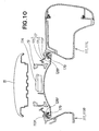
- FIG. 10 shows a state in which the front pawls 128f, 128f of the side trunk 111 are engaged with the front side trunk mounting holes 113f, 113f formed in the rear fender 17.
- the rear fender 17 is disposed below the rear frame 19 which also serves as a seat rail.
- the rear fender 17 is composed of an inner rear fender 17U describing the shape of an arch as a rear wheel housing, and an outer rear fender 17S disposed outward of the inner rear fender 17U.
- the side trunk mounting holes 113f, 113f are provided in the outer rear fender 17S.
- the front pawls 128f, 128f provided to the side trunk 111 are provided with elastic members 179, 179. Therefore, pressing the elastic members 179, 179 into the rear fender 17 and causing the front pawls 128f, 128f to fit tightly in the side trunk mounting holes 113f, 113f of the rear fender 17 makes it unlikely that gaps will form between the pawls and the mounting holes. Therefore, for example, the problem of rattling in the side trunk 111 can be resolved, and the side trunk 111 can be firmly held against the rear fender 17.
- the elastic members may be omitted.
- the left side trunk 111L is denoted as the saddlebag 111, and the left mounting structure is described while a description of the right mounting structure is omitted.
- a side surface 124s of the side trunk 111 on the side facing the vehicle body frame 11 is provided with an engaging concave part 131 for engaging with the latch arm 117 which is attached to the vehicle body frame and which extends from the rider's steps 58L, 58R ( FIG. 9 ).
- the side trunk 111 is provided with the engaging concave part 131 for engaging with the latch arm 117 extending from the rider's step 58 ( FIG. 2 ), a more attractive external appearance is obtained when the side trunk 111 has been mounted.
- FIG. 12 shows a state in which the lower engaging arm 133 of the side trunk 111 is engaged with the ribs 114, 114 extending downward from the side part of the rear fender 17.
- the side trunk 111 can be supported even when the lower engaging arm 133 is short. Since the plurality of ribs 114 extends downward toward the inside of the rear fender 17, the external appearance of the vehicle is not diminished even when the side trunk 111 is removed from the rear fender 17.
- the rear pawl 128r of the side trunk 111 engages with the rear mounting hole 113r of the rear fender 17, as shown in FIG. 13 . Since the rear pawl 128r is provided with an elastic member 179, pressing the elastic member 179 into the rear fender 17 and causing the rear pawl 128r to fit tightly into the rear side trunk mounting hole 113r of the rear fender 17 enables the saddlebag 111 to be mounted on the rear fender 17 without any rattling even when there is a gap between the rear pawl 128r and the side trunk mounting hole 113r.
- FIGS. 14A and 14B comparatively show a conventional side trunk mounting structure and the side trunk mounting structure according to the present embodiment.
- FIG. 14A there are no members covering the four side trunk mounting holes 113Bf, 113Br, 113Bf, 113Br from above, and all of the side trunk mounting holes 113Bf, 113Br, 113Bf, 113Br are exposed from above in the vehicle.
- the side trunk mounting holes 113Bf, 113Br, 113Bf, 113Br are provided in the top surface of the rear frame. Although these side trunk mounting holes 113Bf, 113Br, 113Bf, 113Br are covered by the rear fender 17B, when the side trunks are removed, the mounting holes are exposed, diminishing the external appearance of the vehicle.
- the side trunk mounting holes 113f, 113r, 113f, 113r are formed in the rear fender 17 in the side trunk mounting structure according to the present embodiment shown in FIG. 14B .
- the side trunks 111 are directly mounted in the side trunk mounting holes 113f, 113r, 113f, 113r formed in the rear fender 17 as shown in FIG. 8 . Since the side trunk mounting holes 113f, 113r, 113f, 113r are provided below the rider's seat 15 and the tail light unit 116, the side trunk mounting holes 113f, 113r, 113f, 113r can be obscured from view. Thus, removing the side trunks does not affect the external appearance of the vehicle, which is thus improved.
- the rear fender may be composed of a steel plate, an aluminum alloy, titanium, or another metal material instead of a resin containing glass fibers or carbon fibers.
- the present invention is suitable for use in a two-wheeled motor vehicle having a detachable side trunk.
Landscapes
- Engineering & Computer Science (AREA)
- Mechanical Engineering (AREA)
- Body Structure For Vehicles (AREA)
- Automatic Cycles, And Cycles In General (AREA)
Description
- The present invention relates to an improvement in a side trunk mounting structure for a two-wheeled motor vehicle.
- A side trunk mounting structure according to the preamble of
claim 1 is known fromUS 5,025,883 A . - There are known side trunk mounting structures of two-wheeled motor vehicles having side trunks detachably provided to either side of a rear part of a vehicle body, such as the structure disclosed in, e.g.,
Patent Document 1. - The side trunk mounting structure disclosed in
Patent Document 1 comprises a rear frame installed on a rear part of a vehicle body, and a trunk support part provided to the rear frame. The rear frame has first concave parts set apart from each other in a longitudinal direction, and a second concave part provided between the first concave parts. The trunk support part is configured from the first concave parts and the second concave part. The side trunk has a side trunk latching means, and is mounted to the rear frame by the side trunk latching means being latched onto the trunk support part. - The rear frame is covered by a tail cover. The tail cover has a plurality of openings formed so as to match up with the positions of the first concave parts and the second concave part.
- However, since the mounting structure according to
Patent Document 1 is complex, there is less degree of freedom in the design of the frame, or part of the frame becomes exposed, so that additional consideration must be given to the external appearance. -
- Patent Document 1: Japanese Patent Application Laid-Open Publication No.
2007-55283 - An object of the present invention is to provide a side trunk mounting structure for a two-wheeled motor vehicle whereby the vehicle can have a more attractive external appearance when the side trunk has been mounted, without reducing the degree of freedom in frame designing.
- According to one aspect of the present invention, there is provided a side trunk mounting structure for a two-wheeled motor vehicle, comprising: a rear frame disposed on a rear part of a vehicle body; a rear fender, provided below the rear frame, for covering a rear wheel; a rider's seat, provided above the rear fender, for allowing a rider to sit on; and a side trunk mounted to a side surface of the rear fender, wherein the rear fender has a plurality of side trunk mounting holes for mounting the side trunk, the side trunk has a plurality of pawls, extending inwardly of the vehicle body and bending downward, for hooking into the side trunk mounting holes, and a plurality of lower engaging arms, provided below the respective pawls and extending upwardly inwardly of the vehicle body, for holding the rear fender in cooperation with the pawls, and the side trunk is mounted to the rear fender by the rear fender being held between the pawls and the lower engaging arms.
- Preferably, each of the side trunk mounting holes is provided below the rider's seat.
- Preferably, the rear fender is formed from a resin containing glass fibers or carbon fibers.
- Preferably, the rear fender has a plurality of downwardly extending hanging parts held by the lower engaging arms.
- Preferably, the side trunk mounting structure further comprises at least front and rear fastening parts for fastening the rear fender to the vehicle body frame of the vehicle body, wherein at least one of the plurality of side trunk mounting holes is provided between the two front and rear fastening parts.
- Preferably, the side trunk mounting structure for use in a two-wheeled motor vehicle has a latching arm mounted to a vehicle body frame of the vehicle body and extending from a co-rider's step holder, wherein the side trunk has a side surface facing the vehicle body frame and having an engaging concave part for engaging with the latching arm.
- Each of the pawls which hook into the individual side trunk mounting holes is provided with an elastic member.
- In the present invention, the plurality of side trunk mounting holes is provided to the rear fender, and the side trunk is mounted directly in the side trunk mounting holes provided to the rear fender.
- In conventional side trunk mounting structures, the side trunk is mounted in side trunk mounting holes formed in the top surface of the rear frame. In this case, since the side trunk mounting holes are opened in the top surface of the rear frame, when the side trunk is removed, part of the rear frame can be seen through the side trunk mounting holes, and the external appearance of the vehicle is compromised. Additionally, the degree of freedom in the design of the frame is reduced by a commensurate amount relative to where the side trunk mounting holes are provided in the top surface of the rear frame.
- In the present invention, this is addressed by having the side trunk mounted on the rear fender; therefore, the side trunk mounting portion on the side of the rear frame cannot be seen from the rear fender, and the vehicle can have a more attractive external appearance. Furthermore, the degree of freedom in the design of the frame is not compromised.
- Since the side trunk mounting holes are provided below the rider's seat, they can be obscured from view when the vehicle is seen from above. If the side trunk mounting holes are obscured from view, the external appearance of the vehicle will not readily be affected even when the side trunk is removed, and the vehicle can have an even more attractive external appearance.
- Since the rear fender is formed from a resin containing glass fiber or carbon fiber, the rigidity of the rear fender can be increased, and the load-bearing capacity can be increased.
- Since hanging parts extend downward in the rear fender, the side trunk can be supported even when the lower engaging arms are short.
- Since one of the plurality of side trunk mounting holes is provided between the two front and rear fastening parts, the saddlebag mounting strength can be increased.
- Since the side trunk is provided with engaging concave parts for engaging with latching arms that extend from rider's step holders, the saddlebag can, when in a mounted state, have a more attractive appearance.
- The pawls are provided with elastic members. The pawls are pressed into the rear fender with the elastic members disposed therebetween, and are made to adhere firmly to the saddlebag mounting portion of the rear fender, thereby making it unlikely that gaps will form between the pawls and the saddlebag mounting holes even when there is a change in the mounting relationship between the pawls and the saddlebag mounting holes.
-
-
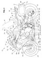
FIG. 1 is a left side view of a two-wheeled motor vehicle to which the side trunk according to the present invention is mounted; -
FIG. 2 is a rear side view of the two-wheeled motor vehicle to which the side trunk is mounted; -
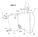
FIG. 3 is a view showing the side trunk mounted on the rear fender; -
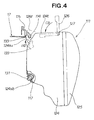
FIG. 4 is a view showing a state in which the lower engaging arms of the side trunk are engaged with the ribs of the rear fender; -
FIG. 5 is a perspective view of the lower engaging arm link assembly provided to the side trunk; -
FIG. 6A is a view showing the lower engaging arms as being housed inside the cover; -
FIG. 6B is a view showing the rear fender as being held between the lower engaging arms and the pawls; -
FIG. 7 is a view showing the handle as being housed in a top surface concave part formed in the side trunk; -
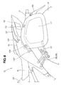
FIG. 8 is a view showing the side trunk as being mounted to the rear fender; -
FIG. 9 is a top surface view of a state in which the side trunk is mounted onto the rear fender shown inFIG. 8 ; -
FIG. 10 is a sectional view taken along line 10-10 ofFIG. 9 ; -
FIG. 11 is a sectional view taken along line 11-11 ofFIG. 9 ; -
FIG. 12 is a sectional view taken along line 12-12 ofFIG. 9 ; -
FIG. 13 is a sectional view taken along line 13-13 ofFIG. 9 ; -
FIG. 14A is a top surface view of the rear part of a conventional two-wheeled motor vehicle; and -
FIG. 14B is a top view of the rear part of the two-wheeled motor vehicle according to the present embodiment. - The preferred embodiments of the present invention are described below with reference to the accompanying drawings.
- A two-
wheeled motor vehicle 10 comprises avehicle body frame 11 as shown inFIG. 1 . Thevehicle body frame 11 is composed of ahead pipe 12; amain frame 14 which extends rearward from thehead pipe 12 and supports anengine 13; and arear frame 19 for supporting a rider'sseat 15 extending rearward from a top part of a rear end of themain frame 14, mounting abattery 16 and other electrical components and the like, and supporting a vehicle bodyrear part 18 including arear fender 17. Themain frame 14 includes apivot plate 22 which is provided to the rear end part of themain frame 14 and which supports aswing arm 28. - The
pivot plate 22 has a pivot shaft 27. The rear swing arm (the swing arm) 28 extends rearward from the pivot shaft 27. Arear cushion unit 29 for absorbing impact is provided between themain frame 14 and theswing arm 28. Arear wheel 31 is mounted on a rear end of theswing arm 28. Therear wheel 31 is driven by a drive shaft (not shown) which links theengine 13 and therear wheel 31 together. - A
front fork 24 is provided to thehead pipe 12. Afront wheel 25 is mounted on the bottom end part of thefront fork 24. A steeringhandlebar 26 for steering thefront wheel 25 is provided to the top end part of thefront fork 24. - The
engine 13 is an engine having four cylinders arranged in a "V"-shaped configuration. Theengine 13 is supported on themain frame 14 with first through fourth support points 30a to 30d disposed therebetween. The first through fourth support points 30a to 30d are provided horizontally along the vehicle width direction. The support points provided to thepivot plate 22 are the third and fourth support points 30c, 30d. In other words, theengine 13 is supported by themain frame 14 and thepivot plate 22. - The V-shaped four-
cylinder engine 13 has acrank case 37, afirst cylinder 35 extending in a forward and upward direction relative to acrankshaft 34 provided to the crankcase 37, and asecond cylinder 36 extending in a rearward and upward direction relative to thecrankshaft 34. Thefirst cylinder 35 and thesecond cylinder 36 are formed into a V shape. When the vehicle is viewed from the side, themain frame 14 lies over thefirst cylinder 35 and thesecond cylinder 36, which constitute a top part of theengine 13. Part of thepivot plate 22 lies above thecrank case 37, which constitutes a rear part of theengine 13. - The V-shaped four-
cylinder engine 13 is connected to anexhaust device 33. Theexhaust device 33 is configured fromexhaust pipes 41a to 41d extending from thecylinders catalyst pipe 45 wherein theexhaust pipes 41a to 41d converge and the exhaust gas is cleaned; anoverall assembly pipe 46 extending from thecatalyst pipe 45; and amuffler 47 connected to theoverall assembly pipe 46. - A
radiator unit 51 cools theengine 13. A frontdisk brake caliper 52 is provided to the front fork. Afront disk plate 53 is held by the frontdisk brake caliper 52 provided to thefront wheel 25. Afront master cylinder 54 is provided to the steeringhandlebar 26. A fuel tank cover 56 covers a fuel tank mounted on themain frame 14 and also serves as acowl 70. Adriver step 57 is mounted on themain frame 14. A rider'sstep 58 is mounted on therear frame 19. - The reference numerals 59, 60, and 61 indicate a headlight, a front fender, and a mirror, respectively. The reference numerals 62 and 65 indicate a rear disk brake caliper and a main stand, respectively. A
rear disk plate 63 is held by the reardisk brake caliper 62 provided to therear wheel 31. - The following is a description of the
cowl 70 constituting what is primarily the externally visible part of the two-wheeledmotor vehicle 10. - The
cowl 70 comprises afront cowl 72 for covering the front of thevehicle body frame 11 via a cowl stay extending from thehead pipe 12, aside cowl 73 which is provided as a continuation of thefront cowl part 72 and which covers the side of the vehicle, and an undercowl 74 provided below theengine 13, it being an object to improve the external appearance of the windshield and the vehicle. - The
front cowl 72 includes anupper center cowl 76 for covering a top region of theheadlight 59, awindscreen 77 extending above theupper center cowl 76, and part of a front upper side cowl 79 to which amiddle cowl 78 covering the side of themain frame 14 is mounted, the frontupper side cowl 79 supporting left and right sides of thewindscreen 77. - The
side cowl 73 includes the frontupper side cowl 79 for supporting the left and right sides of thewindscreen 77; themiddle cowl 78 for covering thehead pipe 12 and the side of themain frame 14; aknee cover 81 for covering a bottom of the fuel tank cover 56 the knee cover being located between legs Rf of a driver R while the vehicle is driven, and a pivot plate cover 82 which is provided below theknee cover 81 and which covers the external surface of thepivot plate 22, which is a structural element of themain frame 14. - To supplement the rear part of the vehicle, the
rear frame 19 is disposed on the rear part of the vehicle body, therear fender 17 for covering therear wheel 31 is provided below therear frame 19, the rider'sseat 15 on which the rider sits is provided above therear fender 17, and side trunks 111L, 111R (seeFIG. 9 ) in which items are stowed are mounted on therear fender 17. - Hereinbelow, the left and right side trunks 111L, 111R (only the nearer symbol 111L is shown) are provided in bilateral symmetry about a center line of the vehicle as shown in
FIG. 9 . Since there is no significant difference between their structures, the left side trunk 111L will be described as aside trunk 111, and the right side trunk 111R will not be described. - The
rear fender 17 covering the top part of therear wheel 31 is mounted on therear frame 19 of thevehicle body frame 11 via front andrear fastening parts FIG. 2 . Two sidetrunk mounting holes side trunk 111 are provided to the front and rear of the rear fender 17 (seeFIG. 8 ), and a plurality of ribs (hanging parts) 114 which engages part of theside trunk 111 extends toward the inside of therear fender 17 between the sidetrunk mounting holes ribs 114 have both a mounting function for mounting the side trunk and a reinforcing function for reinforcing the hanging parts. The sidetrunk mounting holes ribs 114 will be described hereinafter. - A
tail light unit 116 including a stop light and rear turn signal lamps is provided to the rear part of the rider'sseat 15 so as to jut outward to the left and right sides. Alatch arm 117 extends rearward from the rider'sstep 58 and latches onto theside trunk 111, as shown inFIG. 8 . - The
reference numerals - In the present embodiment, there are provided two front and
rear fastening parts rear fender 17 to thevehicle body frame 11, but three or more fastening parts may also be provided. Two front and rear sidetrunk mounting holes - The following is a description of a procedure for mounting the side trunk on the rear part of the vehicle.
- The
side trunk 111 has acase body 124 for storing items, acover body 125 for covering the exterior of thecase body 124, ahandle 126 swingably provided to atop surface 124t of thecase body 124 and used when attaching, removing, and carrying theside trunk 111, front andrear pawls FIG. 13 ) which are provided to a side surface top part 124su of thecase body 124 and which engage with the front and rear sidetrunk mounting holes concave part 131 which is similarly provided to a side surface bottom part 124sb and which engages with a distal end of thelatch arm 117, as shown inFIG. 3 . In other words, theside trunk 111 comprisespawls trunk mounting holes - To describe the mounting method, the
handle 126 is held in the hand, thesaddlebag 111 is brought to the rear part of the vehicle as shown by arrow (1), thepawls saddlebag mounting holes rear fender 17, and the engagingconcave part 131 is engaged with the distal end of thelatch arm 117 as shown by arrow (2). - The side surface top part 124su of the
case body 124 forming theside trunk 111 is provided with a lowerengaging arm 133, separate from the previously describedpawls ribs 114 extending downward from aside part 17S of therear fender 17, as shown inFIG. 4 . This lowerengaging arm 133 moves with the swinging of thehandle 126. - In other words, the
side trunk 111 comprises a lowerengaging arm 133 which is provided below the front andrear pawls rear pawls rear fender 17. - The continuation of the mounting method shall now be described. When the
handle 126 is swung about ashaft 127 as shown by arrow (3), the lowerengaging arm 133 housed within the side surface top part 124su of thecase body 124 protrudes from the side surface top part 124su of the case body as shown by arrow (4) and engages with each of the plurality ofribs 114 provided to therear fender 17. In other words, therear fender 17 is held between thepawls engaging arm part 133, and theside trunk 111 is mounted onto therear fender 17. The series of operations for mounting theside trunk 111 onto therear fender 17 is thus complete. The operations for removing theside trunk 111 from therear fender 17 are preferably performed in the reverse order of the operations described above, and are not described herein. - The following is a description, made with reference to the drawings presented hereinbelow, of the side trunk structure for implementing the mounting method described above.
-
FIG. 5 shows a lower engaging arm link assembly provided to theside trunk 111. The cover for covering an inside top surface 124it of thecase body 124 has been removed. - A
first stay 135 is provided to the inside top surface 124it of thecase body 124. Thehandle 126 is swingably provided to thefirst stay 135. Drivefulcra handle 126 and transmit drive force from thehandle 126 to the lowerengaging arm 133.First arms drive fulcra second stay 139 is provided to the inside top surface 124it, and this stay supports the lowerengaging arm part 133 and other components. Anupper fulcrum 141 and alower fulcrum 142 are provided to the top part of thesecond stay 139. Adrive link 143 is swingably provided to theupper fulcrum 141, and being connected todistal ends 137a of thefirst arms 137, thedrive link 143 drives the lowerengaging arm 133 along with the swinging of thefirst arms 137. Anauxiliary link 144 is swingably provided to thelower fulcrum 142. Anupper drive arm 147 extends from thedrive link 143 to anupper swing point 145 for swingably supporting the lowerengaging arm 133. Anauxiliary arm 148 extends from theauxiliary link 144 to alower swing point 146 for swingably supporting the lowerengaging arm 133. Thefirst stay 135 and thesecond stay 139 are independently mounted onto thecase body 124 separately from each other. - The
handle 126 is stored below thetop surface 124t of thecase body 124 without jutting out from thetop surface 124t. The lowerengaging arm 133 is provided so as to protrude from the side surface top part 124su of the case body 124 (FIG. 4 ). When the lowerengaging arm part 133 is engaged with the rear fender, alock mechanism 161 locks thehandle 126, rendering it inoperable. - The
lock mechanism 161 comprises akey cylinder 162, a firstkey link 164 extending from thekey cylinder 162 to arelay member 163, a secondkey link 165 extending from therelay member 163, alock member 166 which is mounted on the secondkey link 165 and which locks thehandle 126 in conjunction with the movement of the secondkey link 165, and apin 167 which is a fulcrum of therelay member 163. -
FIGS. 6A and 6B show the action of the lower engaging arm link assembly provided to theside trunk 111. In acover 171 for covering the inside top surface 124it (FIG. 5 ) of thecase body 124, anopening 172 is formed so as to allow the lowerengaging arm 133 to protrude therethrough. - In
FIG. 6A , the lowerengaging arm 133 is positioned to the inside of theopening 172. The handle 126 (FIG. 5 ) stands perpendicular to thetop surface 124t of thecase body 124, and theside trunk 111 can easily be carried by grasping thehandle 126. - In
FIG. 6B , the lowerengaging arm 133 protrudes from theopening 172. When thehandle 126 is swung and stored substantially parallel to thetop surface 124t of thecase body 124, the distal ends 137a of thefirst arms 137 move clockwise as shown by arrow b, driving theupper drive arm 147 and causing the lowerengaging arm 133 to protrude. Theauxiliary arm 148 supporting the lowerengaging arm 133 also moves with the protrusion of the lowerengaging arm 133. - The protruding of the lower
engaging arm 133 from theopening 172 causes therear fender 17 to be clamped between thepawl 128 and the lowerengaging arm 133, and theside trunk 111 is mounted onto therear fender 17. - The
handle 126 is stored without jutting out from thetop surface 124t of thecase body 124 as shown inFIG. 7 . When thehandle 126 is in a state where the lowerengaging arm 133 is extended, the lowerengaging arm 133 shall protrude from the opening 172 (FIG. 6 ) formed in thecover 171 when the cover 171 (FIG. 6 ) has been provided. As long as this handle is provided, so that the side trunk will be readily portable, a side trunk having a desirable ease of being attached and removed is obtained. -
FIG. 8 shows a state in which theside trunk 111 has been mounted onto the side surface of therear fender 17. Therear fender 17 is mounted onto therear frame 19 via the front andrear fastening parts saddlebag 111 is mounted onto therear fender 17. - Since at least one of the front and rear side
trunk mounting holes rear fastening parts side trunk 111 can be increased. - The front side
trunk mounting holes seat 15 as shown inFIG. 9 . Thetail light unit 116 is provided to the rear part of the rider'sseat 15. The rear sidetrunk mounting holes tail light unit 116. - Thus, since the four
saddlebag mounting holes seat 15 and thetail light unit 116, the sidetrunk mounting holes - The
rear fender 17 is formed from a resin containing glass fibers or carbon fibers. Therefore, the load-bearing capacity of therear fender 17 can be increased. In the drawings, thereference numerals -
FIG. 10 shows a state in which thefront pawls side trunk 111 are engaged with the front sidetrunk mounting holes rear fender 17. - The
rear fender 17 is disposed below therear frame 19 which also serves as a seat rail. Therear fender 17 is composed of an innerrear fender 17U describing the shape of an arch as a rear wheel housing, and an outerrear fender 17S disposed outward of the innerrear fender 17U. The sidetrunk mounting holes rear fender 17S. - The
front pawls side trunk 111 are provided withelastic members elastic members rear fender 17 and causing thefront pawls trunk mounting holes rear fender 17 makes it unlikely that gaps will form between the pawls and the mounting holes. Therefore, for example, the problem of rattling in theside trunk 111 can be resolved, and theside trunk 111 can be firmly held against therear fender 17. However, the elastic members may be omitted. - Hereinbelow, in
FIGS. 11 through 13 , since the mounting structures of the left and right saddlebags 111L, 111R are disposed in bilateral symmetry about the longitudinal center of the vehicle, the left side trunk 111L is denoted as thesaddlebag 111, and the left mounting structure is described while a description of the right mounting structure is omitted. - As shown in
FIG. 11 , aside surface 124s of theside trunk 111 on the side facing the vehicle body frame 11 (FIG. 11 ) is provided with an engagingconcave part 131 for engaging with thelatch arm 117 which is attached to the vehicle body frame and which extends from the rider'ssteps FIG. 9 ). - Since the
side trunk 111 is provided with the engagingconcave part 131 for engaging with thelatch arm 117 extending from the rider's step 58 (FIG. 2 ), a more attractive external appearance is obtained when theside trunk 111 has been mounted. -
FIG. 12 shows a state in which the lowerengaging arm 133 of theside trunk 111 is engaged with theribs rear fender 17. - Referring also to
FIG. 2 , since the plurality ofribs 114 extends downward in theside part 17s of therear fender 17, theside trunk 111 can be supported even when the lowerengaging arm 133 is short. Since the plurality ofribs 114 extends downward toward the inside of therear fender 17, the external appearance of the vehicle is not diminished even when theside trunk 111 is removed from therear fender 17. - The
rear pawl 128r of theside trunk 111 engages with therear mounting hole 113r of therear fender 17, as shown inFIG. 13 . Since therear pawl 128r is provided with anelastic member 179, pressing theelastic member 179 into therear fender 17 and causing therear pawl 128r to fit tightly into the rear sidetrunk mounting hole 113r of therear fender 17 enables thesaddlebag 111 to be mounted on therear fender 17 without any rattling even when there is a gap between therear pawl 128r and the sidetrunk mounting hole 113r. -
FIGS. 14A and 14B comparatively show a conventional side trunk mounting structure and the side trunk mounting structure according to the present embodiment. - In the conventional side trunk mounting structure as shown in
FIG. 14A , there are no members covering the four side trunk mounting holes 113Bf, 113Br, 113Bf, 113Br from above, and all of the side trunk mounting holes 113Bf, 113Br, 113Bf, 113Br are exposed from above in the vehicle. The side trunk mounting holes 113Bf, 113Br, 113Bf, 113Br are provided in the top surface of the rear frame. Although these side trunk mounting holes 113Bf, 113Br, 113Bf, 113Br are covered by therear fender 17B, when the side trunks are removed, the mounting holes are exposed, diminishing the external appearance of the vehicle. - To prevent such an occurrence, the side
trunk mounting holes rear fender 17 in the side trunk mounting structure according to the present embodiment shown inFIG. 14B . Theside trunks 111 are directly mounted in the sidetrunk mounting holes rear fender 17 as shown inFIG. 8 . Since the sidetrunk mounting holes seat 15 and thetail light unit 116, the sidetrunk mounting holes - The rear fender may be composed of a steel plate, an aluminum alloy, titanium, or another metal material instead of a resin containing glass fibers or carbon fibers.
- The present invention is suitable for use in a two-wheeled motor vehicle having a detachable side trunk.
-
- 10
- Two-wheeled motor vehicle
- 15
- Rider's seat
- 17
- Rear fender
- 19
- Rear frame
- 31
- Rear wheel
- 111, 111L, 111R
- Saddlebags
- 112f, 112r
- Fastening parts
- 113f, 113r
- Saddlebag mounting holes
- 114
- Hanging parts (ribs)
- 117
- Latch arm
- 128f, 128r
- Pawls
- 131
- Engaging concave part
- 133
- Lower engaging arm part
- 179
- Elastic member
Claims (7)
- A side trunk mounting structure for a two-wheeled motor vehicle, comprising:a rear frame (19) disposed on a rear part of a vehicle body;a rear fender (17), provided below the rear frame (19), for covering a rear wheel (31);a rider's seat (15), provided above the rear fender (17), for allowing a rider to sit on; anda side trunk (111) mounted to a side surface of the rear fender (17),wherein the rear fender (17) has a plurality of side trunk mounting holes (113) for mounting the side trunk (111), andthe side trunk (111) has a plurality of pawls (128), extending inwardly of the vehicle body,characterized in that
the plurality of pawls (128) are bending downward, for hooking into the side trunk mounting holes (113), and the side trunk (111) further has a plurality of lower engaging arms (133), provided below the respective pawls (128) and extending upwardly inwardly of the vehicle body, for holding the rear fender (17) in cooperation with the pawls (128), and
the side trunk (111) is mounted to the rear fender (17) by the rear fender (17) being held between the pawls (128) and the lower engaging arms (133). - The side trunk mounting structure of claim 1, wherein each of the side trunk mounting holes (113) is provided below the rider's seat (15).
- The side trunk mounting structure of claim 1, wherein the rear fender (17) is formed from a resin containing one of glass fibers and carbon fibers.
- The side trunk mounting structure of claim 1, wherein the rear fender (17) has a plurality of downwardly extending hanging parts (114) held by the lower engaging arms (133).
- The side trunk mounting structure of claim 1, further comprising at least front and rear fastening parts (112) for fastening the rear fender (17) to a vehicle body frame (11) of the vehicle body, and wherein at least one of the side trunk mounting holes (113) is provided between the front and rear fastening parts (112).
- The side trunk mounting structure of claim 1, for use in a two-wheeled motor vehicle having a latching arm (117) mounted to a vehicle body frame (11) of the vehicle body and extending from a co-rider's step holder (58), wherein the side trunk (111) has a side surface (124) facing the vehicle body frame (11) and having an engaging concave part (131) for engaging with the latching arm (117).
- The side trunk mounting structure of claim 1, wherein each of the pawls (128), which hook into the respective side trunk mounting holes (113), is provided with an elastic member (179).
Applications Claiming Priority (2)
| Application Number | Priority Date | Filing Date | Title |
|---|---|---|---|
| JP2008214181A JP5091804B2 (en) | 2008-08-22 | 2008-08-22 | Saddle bag mounting structure for motorcycles |
| PCT/JP2009/062273 WO2010021209A1 (en) | 2008-08-22 | 2009-07-06 | Side trunk mounting structure for two-wheeled motor vehicle |
Publications (3)
| Publication Number | Publication Date |
|---|---|
| EP2287066A1 EP2287066A1 (en) | 2011-02-23 |
| EP2287066A4 EP2287066A4 (en) | 2011-05-04 |
| EP2287066B1 true EP2287066B1 (en) | 2012-05-23 |
Family
ID=41707088
Family Applications (1)
| Application Number | Title | Priority Date | Filing Date |
|---|---|---|---|
| EP09808145A Not-in-force EP2287066B1 (en) | 2008-08-22 | 2009-07-06 | Side trunk mounting structure for two-wheeled motor vehicle |
Country Status (4)
| Country | Link |
|---|---|
| US (1) | US8864002B2 (en) |
| EP (1) | EP2287066B1 (en) |
| JP (1) | JP5091804B2 (en) |
| WO (1) | WO2010021209A1 (en) |
Families Citing this family (37)
| Publication number | Priority date | Publication date | Assignee | Title |
|---|---|---|---|---|
| JP5030914B2 (en) * | 2008-09-29 | 2012-09-19 | 本田技研工業株式会社 | Canister mounting structure for motorcycles |
| DE102010005272B4 (en) * | 2010-01-20 | 2012-08-16 | Herbert Schwarz | locking system |
| IT1398164B1 (en) * | 2010-02-10 | 2013-02-14 | Givi S R L Unipersonale | COUPLING SYSTEM FOR SUITCASES FOR MOTORCYCLES |
| JP5736876B2 (en) * | 2011-03-18 | 2015-06-17 | 本田技研工業株式会社 | Saddle bag mounting structure for saddle-ride type vehicles |
| JP5701194B2 (en) * | 2011-10-31 | 2015-04-15 | 本田技研工業株式会社 | Saddle-type vehicle trunk device mounting structure, straddle-type vehicle having the structure, and straddle-type vehicle trunk device |
| JP5777493B2 (en) * | 2011-11-02 | 2015-09-09 | 本田技研工業株式会社 | Trunk device for vehicle |
| JP5891062B2 (en) * | 2011-11-22 | 2016-03-22 | 本田技研工業株式会社 | trunk |
| US8944303B1 (en) * | 2012-02-23 | 2015-02-03 | Garry L. Campbell | Clamp-on saddle bag mounting system |
| JP5872447B2 (en) * | 2012-12-13 | 2016-03-01 | 本田技研工業株式会社 | Rear structure of saddle-ride type vehicle |
| DE102013000790B4 (en) * | 2013-01-17 | 2017-10-26 | Touratech Ag | Transport device for attachment to a vehicle frame element |
| CN104106272B (en) | 2013-02-06 | 2019-03-01 | 华为技术有限公司 | System information scheduling method and device |
| JP6071665B2 (en) | 2013-03-13 | 2017-02-01 | 本田技研工業株式会社 | Rear structure of the vehicle |
| JP6118216B2 (en) * | 2013-09-02 | 2017-04-19 | 川崎重工業株式会社 | Motorcycle |
| WO2014181651A1 (en) * | 2013-05-10 | 2014-11-13 | 川崎重工業株式会社 | Motorcycle |
| CN105189966B (en) | 2013-05-10 | 2018-07-24 | 川崎重工业株式会社 | Exhaust device for automatic two-wheeler |
| ES2546200B1 (en) * | 2014-03-20 | 2016-03-23 | Nad, S. L.. | Clamping device for side cases to the chassis of motorcycles and similar vehicles |
| JP2015223902A (en) * | 2014-05-27 | 2015-12-14 | ヤマハ発動機株式会社 | Saddle riding vehicle |
| JP6248015B2 (en) * | 2014-09-01 | 2017-12-13 | 本田技研工業株式会社 | Front fender structure of saddle-ride type vehicle |
| JP6395537B2 (en) * | 2014-09-22 | 2018-09-26 | 川崎重工業株式会社 | Motorcycle pannier mounting structure |
| JP6133912B2 (en) * | 2015-01-23 | 2017-05-24 | 本田技研工業株式会社 | Saddle riding |
| ITUB20154994A1 (en) * | 2015-10-29 | 2017-04-29 | Givi Srl | AUTOMATIC HOOKING SYSTEM FOR MOTORCYCLE CASES. |
| CA2952711C (en) * | 2015-12-22 | 2023-01-03 | Bombardier Recreational Products Inc. | Stackable container assembly |
| WO2017115716A1 (en) * | 2015-12-28 | 2017-07-06 | 本田技研工業株式会社 | Mudguard member for saddled vehicle |
| TWI693173B (en) * | 2017-05-23 | 2020-05-11 | 英屬開曼群島商睿能創意公司 | Fender assembly and vehicle using the same |
| CN111247059B (en) * | 2017-09-29 | 2022-03-29 | 本田技研工业株式会社 | Saddle-ride type vehicle |
| JP7118953B2 (en) * | 2017-11-17 | 2022-08-16 | ヤマハ発動機株式会社 | Exterior resin part for straddle-type vehicle and straddle-type vehicle provided with the same |
| JP7008603B2 (en) * | 2018-09-27 | 2022-01-25 | 本田技研工業株式会社 | Saddle-type vehicle |
| IT201900002225A1 (en) * | 2019-02-15 | 2020-08-15 | Givi S P A | SIDE CASE FOR MOTORCYCLES WITH DEVICE FOR HOOKING TO THE FRAME OF THE IMPROVED VEHICLE. |
| JP6866414B2 (en) | 2019-03-13 | 2021-04-28 | 本田技研工業株式会社 | Storage case |
| IT201900005450A1 (en) * | 2019-04-09 | 2020-10-09 | Givi S P A | SUITCASE OF A MOTORCYCLE. |
| JP2021054129A (en) | 2019-09-27 | 2021-04-08 | ヤマハ発動機株式会社 | Saddle-riding vehicle |
| JP7396161B2 (en) * | 2020-03-27 | 2023-12-12 | スズキ株式会社 | storage case |
| JP7396162B2 (en) * | 2020-03-27 | 2023-12-12 | スズキ株式会社 | storage case |
| JP7339200B2 (en) * | 2020-03-31 | 2023-09-05 | 本田技研工業株式会社 | saddle-riding vehicle |
| KR102405840B1 (en) * | 2021-01-15 | 2022-06-07 | 주식회사 유진환경디자인 | Bag holder for two-wheel vehicle |
| EP4183669B1 (en) * | 2021-11-22 | 2025-09-10 | Nad, S.L. | Bag for motorcycles |
| US12466325B2 (en) * | 2022-08-01 | 2025-11-11 | Austin Hardware & Supply, Inc. | Bin system |
Family Cites Families (16)
| Publication number | Priority date | Publication date | Assignee | Title |
|---|---|---|---|---|
| US4096980A (en) * | 1977-02-14 | 1978-06-27 | Kimstock, Inc. | Universal mounting motorcycle saddlebag bracket |
| JPS6259178A (en) * | 1985-09-09 | 1987-03-14 | 川崎重工業株式会社 | Side bag mounting structure of motorcycle |
| JP2678603B2 (en) * | 1987-10-03 | 1997-11-17 | 本田技研工業株式会社 | Motorcycle with a trunk |
| JP3689169B2 (en) * | 1996-03-19 | 2005-08-31 | 本田技研工業株式会社 | Saddle bag protection device for motorcycles |
| US6293450B1 (en) * | 2000-02-10 | 2001-09-25 | Mathew R. Aron | Quick release mechanism for motorcycle saddlebag |
| US6505765B1 (en) * | 2000-07-19 | 2003-01-14 | Harley-Davidson Motor Company Group, Inc. | Expandable motorcycle saddlebag with top cover |
| US7207470B2 (en) * | 2001-03-15 | 2007-04-24 | Honda Access Corporation | Structure of mounting saddle bag in two-wheeled motor vehicle |
| US20020148869A1 (en) * | 2001-04-16 | 2002-10-17 | Oswald Jerome R. | Saddlebag locking system |
| DE10150055B4 (en) * | 2001-10-10 | 2004-03-04 | Bayerische Motoren Werke Ag | Motorcycle case or motorcycle with a motorcycle case attached to it |
| US7150382B2 (en) * | 2003-12-09 | 2006-12-19 | Zickefoose Mark S | Attachment to motorcycle to safely transport musical instruments |
| US20050150921A1 (en) * | 2004-01-09 | 2005-07-14 | Schneider Daniel H. | Saddlebag mounting system |
| DE102004025748A1 (en) | 2004-05-26 | 2005-12-15 | Bayerische Motoren Werke Ag | Motorcycle with a holding device for a side case |
| JP4673654B2 (en) * | 2005-03-31 | 2011-04-20 | 本田技研工業株式会社 | Side trunk locking device for motorcycles |
| JP2007055283A (en) * | 2005-08-22 | 2007-03-08 | Yamaha Motor Co Ltd | Side trunk mounting structure for motorcycles and motorcycles |
| US20070235698A1 (en) * | 2006-04-05 | 2007-10-11 | General Electric Company | vehicular body part |
| TWM310166U (en) * | 2006-09-27 | 2007-04-21 | C & C Luggage Mfg Co Ltd | Rear container assembly structure of motorbike |
-
2008
- 2008-08-22 JP JP2008214181A patent/JP5091804B2/en not_active Expired - Fee Related
-
2009
- 2009-07-06 WO PCT/JP2009/062273 patent/WO2010021209A1/en not_active Ceased
- 2009-07-06 EP EP09808145A patent/EP2287066B1/en not_active Not-in-force
- 2009-07-06 US US12/996,572 patent/US8864002B2/en active Active
Also Published As
| Publication number | Publication date |
|---|---|
| US20110073627A1 (en) | 2011-03-31 |
| JP5091804B2 (en) | 2012-12-05 |
| US8864002B2 (en) | 2014-10-21 |
| WO2010021209A1 (en) | 2010-02-25 |
| JP2010047164A (en) | 2010-03-04 |
| EP2287066A4 (en) | 2011-05-04 |
| EP2287066A1 (en) | 2011-02-23 |
Similar Documents
| Publication | Publication Date | Title |
|---|---|---|
| US8864002B2 (en) | Side trunk mounting structure for two-wheeled motor vehicle | |
| EP1640257B1 (en) | Motorcycle | |
| JP5129632B2 (en) | Harness holding structure for saddle-ride type vehicles | |
| EP2128007B1 (en) | Motorcycle | |
| CA2448666C (en) | Windscreen device for motorcycle | |
| EP3061679B1 (en) | Rear structure for saddle-ride type vehicle | |
| TW201637920A (en) | Storage part structure of saddle-ride-type vehicle | |
| JP2007210486A (en) | Motorcycle | |
| KR20140038314A (en) | Saddle riding type vehicle | |
| JP2010274852A (en) | Body frame structure of motorcycle | |
| WO2018179298A1 (en) | Vehicle body frame structure of saddle-type vehicle | |
| KR100727723B1 (en) | Grab rails | |
| CN105189269A (en) | Motorcycle | |
| JP4546204B2 (en) | Grab rail | |
| EP2033883B1 (en) | A case assembly for a motor cycle and a motor cycle equipped with such a case assembly | |
| JP2007069677A (en) | Rear structure of saddle riding type vehicle and saddle riding type vehicle | |
| JP4720482B2 (en) | Motorcycle frame cover | |
| JP2011148452A (en) | Rear structure of saddle riding type vehicle | |
| JP3743442B2 (en) | Scooter type motorcycle | |
| JP2530818B2 (en) | Helmet holding structure for motorcycles | |
| EP1470995B1 (en) | Load-carrying frame structure for a vehicle | |
| CN222329892U (en) | Saddle-type vehicle | |
| JP6961006B2 (en) | Support member structure for saddle-mounted vehicles | |
| JP4479454B2 (en) | Anti-theft mounting structure for motorcycles | |
| JP5041439B2 (en) | Motorcycle |
Legal Events
| Date | Code | Title | Description |
|---|---|---|---|
| PUAI | Public reference made under article 153(3) epc to a published international application that has entered the european phase |
Free format text: ORIGINAL CODE: 0009012 |
|
| 17P | Request for examination filed |
Effective date: 20101201 |
|
| AK | Designated contracting states |
Kind code of ref document: A1 Designated state(s): AT BE BG CH CY CZ DE DK EE ES FI FR GB GR HR HU IE IS IT LI LT LU LV MC MK MT NL NO PL PT RO SE SI SK SM TR |
|
| AX | Request for extension of the european patent |
Extension state: AL BA RS |
|
| A4 | Supplementary search report drawn up and despatched |
Effective date: 20110405 |
|
| 17Q | First examination report despatched |
Effective date: 20110419 |
|
| RAP1 | Party data changed (applicant data changed or rights of an application transferred) |
Owner name: HONDA MOTOR CO., LTD. |
|
| RIC1 | Information provided on ipc code assigned before grant |
Ipc: B62J 7/04 20060101ALI20110905BHEP Ipc: B62J 15/00 20060101ALI20110905BHEP Ipc: B62J 11/00 20060101ALI20110905BHEP Ipc: B62J 9/00 20060101AFI20110905BHEP |
|
| GRAP | Despatch of communication of intention to grant a patent |
Free format text: ORIGINAL CODE: EPIDOSNIGR1 |
|
| DAX | Request for extension of the european patent (deleted) | ||
| GRAS | Grant fee paid |
Free format text: ORIGINAL CODE: EPIDOSNIGR3 |
|
| GRAA | (expected) grant |
Free format text: ORIGINAL CODE: 0009210 |
|
| RIN1 | Information on inventor provided before grant (corrected) |
Inventor name: KAJI, KEIICHI Inventor name: HARA, IKUO Inventor name: IIDA, RINATSU Inventor name: TORIYAMA, EIJI Inventor name: AKITA, HIROTOSHI Inventor name: KOGO, SATOSHI |
|
| RAP1 | Party data changed (applicant data changed or rights of an application transferred) |
Owner name: HONDA MOTOR CO., LTD. |
|
| RIN1 | Information on inventor provided before grant (corrected) |
Inventor name: HARA, IKUOC/O HONDA R&D CO., LTD. Inventor name: TORIYAMA, EIJIC/O HONDA R&D CO., LTD. Inventor name: KAJI, KEIICHIC/O HONDA ACCESS CO., LTD. Inventor name: IIDA, RINATSUC/O HONDA R&D CO., LTD. Inventor name: KOGO, SATOSHIC/O HONDA R&D CO., LTD. Inventor name: AKITA, HIROTOSHIC/O HONDA ACCESS CO., LTD. |
|
| AK | Designated contracting states |
Kind code of ref document: B1 Designated state(s): AT BE BG CH CY CZ DE DK EE ES FI FR GB GR HR HU IE IS IT LI LT LU LV MC MK MT NL NO PL PT RO SE SI SK SM TR |
|
| REG | Reference to a national code |
Ref country code: GB Ref legal event code: FG4D |
|
| REG | Reference to a national code |
Ref country code: CH Ref legal event code: EP |
|
| REG | Reference to a national code |
Ref country code: AT Ref legal event code: REF Ref document number: 558949 Country of ref document: AT Kind code of ref document: T Effective date: 20120615 |
|
| REG | Reference to a national code |
Ref country code: IE Ref legal event code: FG4D |
|
| REG | Reference to a national code |
Ref country code: DE Ref legal event code: R096 Ref document number: 602009007247 Country of ref document: DE Effective date: 20120802 |
|
| REG | Reference to a national code |
Ref country code: NL Ref legal event code: VDEP Effective date: 20120523 |
|
| REG | Reference to a national code |
Ref country code: LT Ref legal event code: MG4D Effective date: 20120523 |
|
| PG25 | Lapsed in a contracting state [announced via postgrant information from national office to epo] |
Ref country code: SE Free format text: LAPSE BECAUSE OF FAILURE TO SUBMIT A TRANSLATION OF THE DESCRIPTION OR TO PAY THE FEE WITHIN THE PRESCRIBED TIME-LIMIT Effective date: 20120523 Ref country code: CY Free format text: LAPSE BECAUSE OF FAILURE TO SUBMIT A TRANSLATION OF THE DESCRIPTION OR TO PAY THE FEE WITHIN THE PRESCRIBED TIME-LIMIT Effective date: 20120523 Ref country code: LT Free format text: LAPSE BECAUSE OF FAILURE TO SUBMIT A TRANSLATION OF THE DESCRIPTION OR TO PAY THE FEE WITHIN THE PRESCRIBED TIME-LIMIT Effective date: 20120523 Ref country code: NO Free format text: LAPSE BECAUSE OF FAILURE TO SUBMIT A TRANSLATION OF THE DESCRIPTION OR TO PAY THE FEE WITHIN THE PRESCRIBED TIME-LIMIT Effective date: 20120823 Ref country code: FI Free format text: LAPSE BECAUSE OF FAILURE TO SUBMIT A TRANSLATION OF THE DESCRIPTION OR TO PAY THE FEE WITHIN THE PRESCRIBED TIME-LIMIT Effective date: 20120523 Ref country code: IS Free format text: LAPSE BECAUSE OF FAILURE TO SUBMIT A TRANSLATION OF THE DESCRIPTION OR TO PAY THE FEE WITHIN THE PRESCRIBED TIME-LIMIT Effective date: 20120923 |
|
| REG | Reference to a national code |
Ref country code: AT Ref legal event code: MK05 Ref document number: 558949 Country of ref document: AT Kind code of ref document: T Effective date: 20120523 |
|
| PG25 | Lapsed in a contracting state [announced via postgrant information from national office to epo] |
Ref country code: HR Free format text: LAPSE BECAUSE OF FAILURE TO SUBMIT A TRANSLATION OF THE DESCRIPTION OR TO PAY THE FEE WITHIN THE PRESCRIBED TIME-LIMIT Effective date: 20120523 Ref country code: LV Free format text: LAPSE BECAUSE OF FAILURE TO SUBMIT A TRANSLATION OF THE DESCRIPTION OR TO PAY THE FEE WITHIN THE PRESCRIBED TIME-LIMIT Effective date: 20120523 Ref country code: GR Free format text: LAPSE BECAUSE OF FAILURE TO SUBMIT A TRANSLATION OF THE DESCRIPTION OR TO PAY THE FEE WITHIN THE PRESCRIBED TIME-LIMIT Effective date: 20120824 Ref country code: PT Free format text: LAPSE BECAUSE OF FAILURE TO SUBMIT A TRANSLATION OF THE DESCRIPTION OR TO PAY THE FEE WITHIN THE PRESCRIBED TIME-LIMIT Effective date: 20120924 Ref country code: SI Free format text: LAPSE BECAUSE OF FAILURE TO SUBMIT A TRANSLATION OF THE DESCRIPTION OR TO PAY THE FEE WITHIN THE PRESCRIBED TIME-LIMIT Effective date: 20120523 |
|
| PG25 | Lapsed in a contracting state [announced via postgrant information from national office to epo] |
Ref country code: BE Free format text: LAPSE BECAUSE OF FAILURE TO SUBMIT A TRANSLATION OF THE DESCRIPTION OR TO PAY THE FEE WITHIN THE PRESCRIBED TIME-LIMIT Effective date: 20120523 |
|
| PG25 | Lapsed in a contracting state [announced via postgrant information from national office to epo] |
Ref country code: DK Free format text: LAPSE BECAUSE OF FAILURE TO SUBMIT A TRANSLATION OF THE DESCRIPTION OR TO PAY THE FEE WITHIN THE PRESCRIBED TIME-LIMIT Effective date: 20120523 Ref country code: CZ Free format text: LAPSE BECAUSE OF FAILURE TO SUBMIT A TRANSLATION OF THE DESCRIPTION OR TO PAY THE FEE WITHIN THE PRESCRIBED TIME-LIMIT Effective date: 20120523 Ref country code: NL Free format text: LAPSE BECAUSE OF FAILURE TO SUBMIT A TRANSLATION OF THE DESCRIPTION OR TO PAY THE FEE WITHIN THE PRESCRIBED TIME-LIMIT Effective date: 20120523 Ref country code: SK Free format text: LAPSE BECAUSE OF FAILURE TO SUBMIT A TRANSLATION OF THE DESCRIPTION OR TO PAY THE FEE WITHIN THE PRESCRIBED TIME-LIMIT Effective date: 20120523 Ref country code: AT Free format text: LAPSE BECAUSE OF FAILURE TO SUBMIT A TRANSLATION OF THE DESCRIPTION OR TO PAY THE FEE WITHIN THE PRESCRIBED TIME-LIMIT Effective date: 20120523 Ref country code: RO Free format text: LAPSE BECAUSE OF FAILURE TO SUBMIT A TRANSLATION OF THE DESCRIPTION OR TO PAY THE FEE WITHIN THE PRESCRIBED TIME-LIMIT Effective date: 20120523 Ref country code: EE Free format text: LAPSE BECAUSE OF FAILURE TO SUBMIT A TRANSLATION OF THE DESCRIPTION OR TO PAY THE FEE WITHIN THE PRESCRIBED TIME-LIMIT Effective date: 20120523 |
|
| PG25 | Lapsed in a contracting state [announced via postgrant information from national office to epo] |
Ref country code: PL Free format text: LAPSE BECAUSE OF FAILURE TO SUBMIT A TRANSLATION OF THE DESCRIPTION OR TO PAY THE FEE WITHIN THE PRESCRIBED TIME-LIMIT Effective date: 20120523 Ref country code: MC Free format text: LAPSE BECAUSE OF NON-PAYMENT OF DUE FEES Effective date: 20120731 Ref country code: MK Free format text: LAPSE BECAUSE OF FAILURE TO SUBMIT A TRANSLATION OF THE DESCRIPTION OR TO PAY THE FEE WITHIN THE PRESCRIBED TIME-LIMIT Effective date: 20120523 |
|
| PLBE | No opposition filed within time limit |
Free format text: ORIGINAL CODE: 0009261 |
|
| STAA | Information on the status of an ep patent application or granted ep patent |
Free format text: STATUS: NO OPPOSITION FILED WITHIN TIME LIMIT |
|
| PG25 | Lapsed in a contracting state [announced via postgrant information from national office to epo] |
Ref country code: ES Free format text: LAPSE BECAUSE OF FAILURE TO SUBMIT A TRANSLATION OF THE DESCRIPTION OR TO PAY THE FEE WITHIN THE PRESCRIBED TIME-LIMIT Effective date: 20120903 |
|
| 26N | No opposition filed |
Effective date: 20130226 |
|
| REG | Reference to a national code |
Ref country code: IE Ref legal event code: MM4A |
|
| REG | Reference to a national code |
Ref country code: DE Ref legal event code: R097 Ref document number: 602009007247 Country of ref document: DE Effective date: 20130226 |
|
| PG25 | Lapsed in a contracting state [announced via postgrant information from national office to epo] |
Ref country code: BG Free format text: LAPSE BECAUSE OF FAILURE TO SUBMIT A TRANSLATION OF THE DESCRIPTION OR TO PAY THE FEE WITHIN THE PRESCRIBED TIME-LIMIT Effective date: 20120823 Ref country code: IE Free format text: LAPSE BECAUSE OF NON-PAYMENT OF DUE FEES Effective date: 20120706 Ref country code: MT Free format text: LAPSE BECAUSE OF FAILURE TO SUBMIT A TRANSLATION OF THE DESCRIPTION OR TO PAY THE FEE WITHIN THE PRESCRIBED TIME-LIMIT Effective date: 20120523 |
|
| REG | Reference to a national code |
Ref country code: CH Ref legal event code: PL |
|
| GBPC | Gb: european patent ceased through non-payment of renewal fee |
Effective date: 20130706 |
|
| PG25 | Lapsed in a contracting state [announced via postgrant information from national office to epo] |
Ref country code: LI Free format text: LAPSE BECAUSE OF NON-PAYMENT OF DUE FEES Effective date: 20130731 Ref country code: GB Free format text: LAPSE BECAUSE OF NON-PAYMENT OF DUE FEES Effective date: 20130706 Ref country code: TR Free format text: LAPSE BECAUSE OF FAILURE TO SUBMIT A TRANSLATION OF THE DESCRIPTION OR TO PAY THE FEE WITHIN THE PRESCRIBED TIME-LIMIT Effective date: 20120523 Ref country code: CH Free format text: LAPSE BECAUSE OF NON-PAYMENT OF DUE FEES Effective date: 20130731 |
|
| PG25 | Lapsed in a contracting state [announced via postgrant information from national office to epo] |
Ref country code: SM Free format text: LAPSE BECAUSE OF FAILURE TO SUBMIT A TRANSLATION OF THE DESCRIPTION OR TO PAY THE FEE WITHIN THE PRESCRIBED TIME-LIMIT Effective date: 20120523 Ref country code: LU Free format text: LAPSE BECAUSE OF NON-PAYMENT OF DUE FEES Effective date: 20120706 |
|
| PG25 | Lapsed in a contracting state [announced via postgrant information from national office to epo] |
Ref country code: HU Free format text: LAPSE BECAUSE OF FAILURE TO SUBMIT A TRANSLATION OF THE DESCRIPTION OR TO PAY THE FEE WITHIN THE PRESCRIBED TIME-LIMIT Effective date: 20090706 |
|
| REG | Reference to a national code |
Ref country code: FR Ref legal event code: PLFP Year of fee payment: 8 |
|
| REG | Reference to a national code |
Ref country code: FR Ref legal event code: PLFP Year of fee payment: 9 |
|
| REG | Reference to a national code |
Ref country code: FR Ref legal event code: PLFP Year of fee payment: 10 |
|
| PGFP | Annual fee paid to national office [announced via postgrant information from national office to epo] |
Ref country code: FR Payment date: 20190619 Year of fee payment: 11 |
|
| PGFP | Annual fee paid to national office [announced via postgrant information from national office to epo] |
Ref country code: DE Payment date: 20190625 Year of fee payment: 11 Ref country code: IT Payment date: 20190719 Year of fee payment: 11 |
|
| REG | Reference to a national code |
Ref country code: DE Ref legal event code: R084 Ref document number: 602009007247 Country of ref document: DE |
|
| REG | Reference to a national code |
Ref country code: DE Ref legal event code: R119 Ref document number: 602009007247 Country of ref document: DE |
|
| PG25 | Lapsed in a contracting state [announced via postgrant information from national office to epo] |
Ref country code: FR Free format text: LAPSE BECAUSE OF NON-PAYMENT OF DUE FEES Effective date: 20200731 |
|
| PG25 | Lapsed in a contracting state [announced via postgrant information from national office to epo] |
Ref country code: DE Free format text: LAPSE BECAUSE OF NON-PAYMENT OF DUE FEES Effective date: 20210202 |
|
| PG25 | Lapsed in a contracting state [announced via postgrant information from national office to epo] |
Ref country code: IT Free format text: LAPSE BECAUSE OF NON-PAYMENT OF DUE FEES Effective date: 20200706 |