EP2286974A1 - Forming device and method for removing an object - Google Patents
Forming device and method for removing an object Download PDFInfo
- Publication number
- EP2286974A1 EP2286974A1 EP10008688A EP10008688A EP2286974A1 EP 2286974 A1 EP2286974 A1 EP 2286974A1 EP 10008688 A EP10008688 A EP 10008688A EP 10008688 A EP10008688 A EP 10008688A EP 2286974 A1 EP2286974 A1 EP 2286974A1
- Authority
- EP
- European Patent Office
- Prior art keywords
- guide
- mold
- ejection
- recess
- guide element
- Prior art date
- Legal status (The legal status is an assumption and is not a legal conclusion. Google has not performed a legal analysis and makes no representation as to the accuracy of the status listed.)
- Granted
Links
Images


Classifications
-
- B—PERFORMING OPERATIONS; TRANSPORTING
- B29—WORKING OF PLASTICS; WORKING OF SUBSTANCES IN A PLASTIC STATE IN GENERAL
- B29C—SHAPING OR JOINING OF PLASTICS; SHAPING OF MATERIAL IN A PLASTIC STATE, NOT OTHERWISE PROVIDED FOR; AFTER-TREATMENT OF THE SHAPED PRODUCTS, e.g. REPAIRING
- B29C45/00—Injection moulding, i.e. forcing the required volume of moulding material through a nozzle into a closed mould; Apparatus therefor
- B29C45/17—Component parts, details or accessories; Auxiliary operations
- B29C45/40—Removing or ejecting moulded articles
- B29C45/44—Removing or ejecting moulded articles for undercut articles
- B29C45/4435—Removing or ejecting moulded articles for undercut articles using inclined, tiltable or flexible undercut forming elements driven by the ejector means
-
- B—PERFORMING OPERATIONS; TRANSPORTING
- B22—CASTING; POWDER METALLURGY
- B22D—CASTING OF METALS; CASTING OF OTHER SUBSTANCES BY THE SAME PROCESSES OR DEVICES
- B22D17/00—Pressure die casting or injection die casting, i.e. casting in which the metal is forced into a mould under high pressure
- B22D17/20—Accessories: Details
- B22D17/22—Dies; Die plates; Die supports; Cooling equipment for dies; Accessories for loosening and ejecting castings from dies
- B22D17/2236—Equipment for loosening or ejecting castings from dies
-
- B—PERFORMING OPERATIONS; TRANSPORTING
- B29—WORKING OF PLASTICS; WORKING OF SUBSTANCES IN A PLASTIC STATE IN GENERAL
- B29C—SHAPING OR JOINING OF PLASTICS; SHAPING OF MATERIAL IN A PLASTIC STATE, NOT OTHERWISE PROVIDED FOR; AFTER-TREATMENT OF THE SHAPED PRODUCTS, e.g. REPAIRING
- B29C33/00—Moulds or cores; Details thereof or accessories therefor
- B29C33/44—Moulds or cores; Details thereof or accessories therefor with means for, or specially constructed to facilitate, the removal of articles, e.g. of undercut articles
- B29C33/48—Moulds or cores; Details thereof or accessories therefor with means for, or specially constructed to facilitate, the removal of articles, e.g. of undercut articles with means for collapsing or disassembling
-
- B—PERFORMING OPERATIONS; TRANSPORTING
- B29—WORKING OF PLASTICS; WORKING OF SUBSTANCES IN A PLASTIC STATE IN GENERAL
- B29C—SHAPING OR JOINING OF PLASTICS; SHAPING OF MATERIAL IN A PLASTIC STATE, NOT OTHERWISE PROVIDED FOR; AFTER-TREATMENT OF THE SHAPED PRODUCTS, e.g. REPAIRING
- B29C43/00—Compression moulding, i.e. applying external pressure to flow the moulding material; Apparatus therefor
- B29C43/32—Component parts, details or accessories; Auxiliary operations
- B29C43/36—Moulds for making articles of definite length, i.e. discrete articles
- B29C43/42—Moulds for making articles of definite length, i.e. discrete articles for undercut articles
-
- B—PERFORMING OPERATIONS; TRANSPORTING
- B29—WORKING OF PLASTICS; WORKING OF SUBSTANCES IN A PLASTIC STATE IN GENERAL
- B29C—SHAPING OR JOINING OF PLASTICS; SHAPING OF MATERIAL IN A PLASTIC STATE, NOT OTHERWISE PROVIDED FOR; AFTER-TREATMENT OF THE SHAPED PRODUCTS, e.g. REPAIRING
- B29C43/00—Compression moulding, i.e. applying external pressure to flow the moulding material; Apparatus therefor
- B29C43/32—Component parts, details or accessories; Auxiliary operations
- B29C43/50—Removing moulded articles
-
- B—PERFORMING OPERATIONS; TRANSPORTING
- B29—WORKING OF PLASTICS; WORKING OF SUBSTANCES IN A PLASTIC STATE IN GENERAL
- B29C—SHAPING OR JOINING OF PLASTICS; SHAPING OF MATERIAL IN A PLASTIC STATE, NOT OTHERWISE PROVIDED FOR; AFTER-TREATMENT OF THE SHAPED PRODUCTS, e.g. REPAIRING
- B29C43/00—Compression moulding, i.e. applying external pressure to flow the moulding material; Apparatus therefor
- B29C43/32—Component parts, details or accessories; Auxiliary operations
- B29C43/36—Moulds for making articles of definite length, i.e. discrete articles
- B29C43/42—Moulds for making articles of definite length, i.e. discrete articles for undercut articles
- B29C2043/425—Moulds for making articles of definite length, i.e. discrete articles for undercut articles mould parts or sliders being movable independently from the mould halves for making undercut portions
-
- B—PERFORMING OPERATIONS; TRANSPORTING
- B29—WORKING OF PLASTICS; WORKING OF SUBSTANCES IN A PLASTIC STATE IN GENERAL
- B29C—SHAPING OR JOINING OF PLASTICS; SHAPING OF MATERIAL IN A PLASTIC STATE, NOT OTHERWISE PROVIDED FOR; AFTER-TREATMENT OF THE SHAPED PRODUCTS, e.g. REPAIRING
- B29C43/00—Compression moulding, i.e. applying external pressure to flow the moulding material; Apparatus therefor
- B29C43/32—Component parts, details or accessories; Auxiliary operations
- B29C43/50—Removing moulded articles
- B29C2043/503—Removing moulded articles using ejector pins, rods
-
- B—PERFORMING OPERATIONS; TRANSPORTING
- B29—WORKING OF PLASTICS; WORKING OF SUBSTANCES IN A PLASTIC STATE IN GENERAL
- B29C—SHAPING OR JOINING OF PLASTICS; SHAPING OF MATERIAL IN A PLASTIC STATE, NOT OTHERWISE PROVIDED FOR; AFTER-TREATMENT OF THE SHAPED PRODUCTS, e.g. REPAIRING
- B29C45/00—Injection moulding, i.e. forcing the required volume of moulding material through a nozzle into a closed mould; Apparatus therefor
- B29C45/17—Component parts, details or accessories; Auxiliary operations
- B29C45/40—Removing or ejecting moulded articles
- B29C45/4005—Ejector constructions; Ejector operating mechanisms
- B29C45/401—Ejector pin constructions or mountings
- B29C2045/4026—Ejectors with internal cooling
Landscapes
- Engineering & Computer Science (AREA)
- Mechanical Engineering (AREA)
- Manufacturing & Machinery (AREA)
- Moulds For Moulding Plastics Or The Like (AREA)
Abstract
Description
Die Erfindung betrifft eine Formvorrichtung zur Herstellung von geformten Gegenständen sowie ein Verfahren zum Entformen eines Gegenstandes in einer Formvorrichtung.The invention relates to a molding apparatus for producing shaped articles and to a method for demolding an article in a molding apparatus.
Formvorrichtungen werden auch als Werkzeuge bezeichnet und finden allgemein Verwendung zur Herstellung von geformten Gegenständen. Dazu umfasst eine Formvorrichtung üblicherweise zwei Formhälften, die eine Formoberseite sowie eine Formunterseite bilden. Die Formoberseite und die Formunterseite werden auch als Angussseite und Ausstoßseite bezeichnet. Dazwischen ist bei einer geschlossenen Formvorrichtung ein Hohlraum gebildet.Forming devices are also referred to as tools and are commonly used for the production of shaped articles. For this purpose, a molding device usually comprises two mold halves which form a mold top and a mold bottom. The upper side of the mold and the lower side of the mold are also called the sprue side and the ejection side. In between, a cavity is formed in a closed mold device.
Zum Formen eines Gegenstandes werden die Formoberseite und die Formunterseite über einen Schließmechanismus verschlossen. Ein zunächst unförmiges Material wird in den Hohlraum eingebracht und geformt. Bei dem Material kann es sich beispielsweise um Granulat oder auch um eine Schmelze handeln. Zum Einbringen des Materials in die Form sind verschiedene Verfahren bekannt. Die Materialien können beispielsweise Metall oder Kunststoff umfassen.For molding an article, the mold top and the mold bottom are closed by a lock mechanism. An initially bulky material is introduced into the cavity and shaped. The material may, for example, be granules or else a melt. For introducing the material into the mold, various methods are known. The materials may include, for example, metal or plastic.
Formvorrichtungen können beispielsweise beim Spritzgießen bzw. Spritzgussverfahren eingesetzt werden. Dieses Urformverfahren dient hauptsächlich zur Kunststoffverarbeitung. Dabei wird ein Kunststoffgranulat eingeschmolzen und die flüssige Kunststoffschmelze über Zufuhrleitungen in den Hohlraum eingespritzt. Nach dem Erkalten der Schmelze werden die beiden Formhälften auseinander gefahren, wobei der erstarrte Gegenstand aus der Form entnommen werden kann.Forming devices can be used for example in injection molding or injection molding. This primary molding process is mainly used for plastics processing. In this case, a plastic granules is melted and injected the liquid plastic melt via supply lines into the cavity. After cooling the melt, the two mold halves are moved apart, wherein the solidified object can be removed from the mold.
Auch ist der Einsatz von Formvorrichtungen bei Druckgussverfahren bekannt. Hierbei werden metallische Materialien mit einem niedrigen Schmelzpunkt, beispielsweise Aluminium, Zink oder Magnesium, verwendet. Bei den verschiedenen Druckgussverfahren wird die flüssige Schmelze unter hohem Druck und mit hoher Geschwindigkeit in die Form eingebracht. Auch hier erstarrt die Schmelze nach kurzer Zeit.Also, the use of molding devices in die-casting is known. In this case, metallic materials having a low melting point, for example aluminum, zinc or magnesium, are used. In the various die casting processes, the liquid melt is introduced into the mold under high pressure and at high speed. Again, the melt solidifies after a short time.
Nach dem Öffnen der Formhälften verbleibt der geformte Gegenstand, beispielsweise ein Spritzling oder ein Gießling, zunächst in der unteren oder oberen Formhälfte und wird anschließend über eine Ausstoßvorrichtung ausgeworfen. Sofern der hergestellte Gegenstand hinterschnittige Geometrien aufweist, wäre kein Öffnen der Formoberseite und/oder eine Entnahme des Gegenstandes aus der Formhälfte in der so genannten Trennebene nach oben beziehungsweise nach unten möglich. Hinterschnittige Geometrien meint Aus- oder Einbuchtungen, Überstände und ähnliches am herzustellenden Gegenstand, die eine Formhälfte oder Form von innen oder von außen hintergreift. Entformen meint die Entnahme bzw. das Ausstoßen des gefertigten Gegenstandes aus der Form. Die Position der Hinterschneidung bestimmt die Öffnungsrichtung beim Entformen und den Aufwand bei Herstellung einer Formvorrichtung.After opening the mold halves, the molded article, such as a sprue or a casting, initially remains in the lower or upper mold half and is subsequently ejected via an ejector. If the article produced has undercut geometries, it would not be possible to open the top of the mold and / or remove the article from the mold half in the so-called parting plane upwards or downwards. Undercut geometries means bulges or protrusions, protrusions and the like on the object to be produced, which engages behind a mold half or form from the inside or from the outside. Removal means the removal or ejection of the finished article from the mold. The position of the undercut determines the opening direction during demoulding and the effort in producing a molding device.
Zum Entformen hinterschnittiger Geometrien sind aus dem Stand der Technik hydraulisch betätigte Schiebermechanismen bekannt. Diese Schiebermechanismen werden beim Spritzgießen und Druckgießen verwendet und weisen einen komplizierten Aufbau auf. Selbst kleine Hinterschneidungen am herzustellenden Gegenstand können die Herstellung einer Formvorrichtung stark verteuern.For demolding undercut geometries hydraulically operated slide mechanisms are known from the prior art. These slide mechanisms are used in injection molding and die casting and have a complicated structure. Even small undercuts on the object to be manufactured can greatly increase the cost of manufacturing a molding device.
Ferner sind aus dem Stand der Technik hydraulisch betätigte, sogenannte Führungspinolen bekannt, die einen hergestellten Gegenstand zum Entformen hinterschnittiger Geometrien führen. Solche Führungspinolen sind an ihrer Unterseite in einer Kulissenführung verschiebbar geführt, beispielsweise über einen Hydraulikzylinder. Dabei wirken hohe Kräfte, unter anderem Knickkräfte, auf die Kulissenführung und den Hydraulikzylinder, so dass die Führungspinole und der Hydraulikzylinder verkanten können. Das Verkanten kann zu einer Blockade der gesamten Formvorrichtung führen.Furthermore, hydraulically operated, so-called guide quills are known from the prior art, which lead a manufactured object for demolding undercut geometries. Such guide sleeves are slidably guided on their underside in a slotted guide, for example via a hydraulic cylinder. High forces, including bending forces, act on the slotted guide and the hydraulic cylinder so that the guide spindle and the hydraulic cylinder can tilt. The tilting can lead to a blockage of the entire molding apparatus.
Weiter haben bekannte Führungspinolen einen hohen Platzbedarf, da auch der Hydraulikzylinder in der Formvorrichtung untergebracht werden muss. Oftmals sind mehrere Führungspinolen erforderlich, die allesamt jeweils mit einem Hydraulikzylinder verbunden sind. Dies erfordert wiederum große Ausnehmungen im Werkzeug bzw. der Formvorrichtung. Die Ausnehmungen schwächen das Werkzeug. Um diese Schwächung auszugleichen, muss die Formvorrichtung entsprechend vergrößert werden. Dazu können beispielsweise zusätzliche Platten montiert werden. Erfolgt keine Vergrößerung bzw. Verstärkung der Formvorrichtung, kann die Schwächung eine sogenannte Gratbildung verursachen. Dies kann wiederum zu ungewünschte Veränderungen an der Oberfläche der herzustellenden Gegenstände führen, was die Qualität mindert. Darüber hinaus sind diese bekannten Führungspinolen nur bis maximal 45° zur Hauptentformungsrichtung verschwenkbar.Next have known guide quill high space requirements, as well as the hydraulic cylinder must be accommodated in the molding apparatus. Often several Führungspinolen are required, all of which are each connected to a hydraulic cylinder. This in turn requires large recesses in the tool or the molding device. The recesses weaken the tool. To compensate for this weakening, the mold device must be increased accordingly. For this example, additional plates can be mounted. If no enlargement or reinforcement of the molding device, the weakening can cause a so-called burr formation. This in turn can lead to undesirable changes to the surface of the objects to be produced, which reduces the quality. In addition, these known guide quills can only be pivoted to a maximum of 45 ° to the main demolding.
Ferner zeigt die
Insgesamt sind die aus dem Stand der Technik bekannten Lösungen kompliziert im Aufbau, kostenintensiv in der Herstellung und nur begrenzt einsetzbar.Overall, the known from the prior art solutions are complicated in structure, costly to manufacture and limited use.
Vor diesem Hintergrund ist es Ziel der Erfindung eine verbesserte Formvorrichtung sowie ein verbessertes Verfahren zum Entformen eines Gegenstandes in einer Formvorrichtung bereitzustellen.Against this background, the object of the invention is to provide an improved molding apparatus and an improved method for demolding an article in a molding apparatus.
Diese Ziele werden durch die Gegenstände der unabhängigen Ansprüche erreicht. Bevorzugte Ausführungsformen sind in den Unteransprüchen angegeben.These objects are achieved by the subject-matter of the independent claims. Preferred embodiments are specified in the subclaims.
Nach Anspruch 1 umfasst eine erfindungsgemäße Formvorrichtung zum Spritz- oder Druckgießen wenigstens ein erstes Formelement, wenigstens ein zweites Formelement, wenigstens eine Öffnungsvorrichtung zum Öffnen oder Schließen der Formelemente, und wenigstens ein separates Auswurfelement, welches an der Rückseite eines der Formelemente angeordnet ist und über ein Kopplungselement zum Entformen eines Gegenstandes mit wenigstens einem der Formelemente gekoppelt ist, wobei ein erstes Führungselement im Auswurfelement verschiebbar angeordnet ist und von einem zweiten starren Führungselement geführt ist., das Kopplungselement vom ersten Führungselement geführt ist, und im ersten Führungselement eine Ausnehmung ausgebildet ist, in die das zweite Führungselement zur Bildung einer Zwangsführung einsetzbar ist.According to
Ebenso stellt die Erfindung auch ein Verfahren zum Entformen eines Gegenstandes mit einer erfindungsgemäßen Formvorrichtung bereit. Das Verfahren umfasst die Schritte: Schließen eines ersten und eines zweiten Formelements; Einbringen, Formen und Aushärten einer Formmasse in einem zwischen den Formelementen gebildeten Hohlraum; Betätigen eines separat, an der Rückseite eines der Formelemente angeordneten Auswurfelements beim oder nach dem Öffnen der Formelemente, wobei ein über ein Kopplungselement mit wenigstens einem Formelement gekoppeltes erstes Führungselement im Auswurfelement verschoben und von einem zweiten starren Führungselement geführt wird, und wobei im ersten Führungselement eine Ausnehmung ausgebildet ist, in der das zweite Führungselement zur Bildung einer Zwangsführung geführt wird.Likewise, the invention also provides a method for demolding an article with a molding apparatus according to the invention. The method comprises the steps of: closing a first and a second feature element; Introducing, shaping and curing a molding compound in a cavity formed between the mold elements; Actuating a separately arranged on the back of one of the mold elements ejection element during or after the opening of the mold elements, wherein a coupled via a coupling element with at least one mold element first guide element is displaced in the ejection element and guided by a second rigid guide element, and wherein in the first guide element Recess is formed, in which the second guide element is guided to form a forced operation.
Die Formvorrichtung kann beispielsweise im Spritzgussverfahren zur Herstellung von Gegenständen aus Kunststoff oder im Druckgussverfahren für die Herstellung von metallischen Gegenständen Verwendung finden. Sowohl Spritzguss- als auch Druckgussverfahren haben den Vorteil, dass sich große Stückzahlen mit dem gleichen Satz an Formenelementen herstellen lassen.The molding apparatus can be used, for example, in the injection molding process for the production of articles made of plastic or in the die casting process for the production of metallic objects. Both injection molding and die casting processes have the advantage that large quantities can be produced with the same set of mold elements.
In den Innenseiten der Formelemente, die auch als Formen oder als Formhälften bezeichnet werden, sind mit Hilfe von Werkzeugmaschinen die Formkonturen des herzustellenden Gegenstandes als Negativabdruck eingearbeitet. Insgesamt können beliebig viele Formelemente verwendet werden, die beispielsweise in verschiedenen Ebenen geöffnet werden. Bevorzugt werden zwei Formhälften verwendet, da dies einen einfachen Aufbau der Formvorrichtung zur Folge hat. Die geschlossenen Formelemente bzw. Formhälften bilden zusammen einen Hohlraum in dem der herzustellende Gegenstand hergestellt wird. Um den Verschleiß der Formvorrichtung zu reduzieren, kann gehärteter oder vergüteter Werkzeugstahl und/oder Hartmetall verwendet werden.In the inner sides of the mold elements, which are also referred to as molds or as mold halves, the shape contours of the article to be produced are incorporated as a negative impression with the aid of machine tools. Overall, any number of form elements can be used, for example, in different Layers are opened. Preferably, two mold halves are used, as this has a simple structure of the molding device result. The closed mold elements or mold halves together form a cavity in which the article to be produced is produced. To reduce wear on the molding apparatus, hardened or tempered tool steel and / or cemented carbide may be used.
Eine Öffnungs/Schließvorrichtung kann zum Öffnen oder Schließen der Formelemente beispielsweise einen pneumatischen, hydraulischen oder elektrisch betätigten Hubmechanismus umfassen.An opening / closing device may comprise, for example, a pneumatic, hydraulic or electrically actuated lifting mechanism for opening or closing the mold elements.
Das Auswurfelement kann als Auswerferplatte im ersten und/oder zweiten Formelement angeordnet sein und beispielsweise auch einen pneumatischen, hydraulischen oder elektrisch betätigten Hubmechanismus umfassen. Der Hubmechanismus ist ausgelegt, um die Auswerferplatte und das Kopplungselement zum Ausstoßen eines hergestellten Gegenstandes zu Heben und danach zu senken. Der Hubmechanismus des Auswerfelements kann auch mit dem Hub der Öffnungsvorrichtung gekoppelt sein. Vorteilhaft ist die Auswerferplatte gering dimensioniert, so dass die Formvorrichtung wenig geschwächt wird. Damit lässt sich eine Gratbildung vermindern bzw. verhindern.The ejection element can be arranged as an ejector plate in the first and / or second mold element and, for example, also comprise a pneumatic, hydraulic or electrically actuated lifting mechanism. The lifting mechanism is configured to lift the ejector plate and the coupling member for ejecting a manufactured article and thereafter lowering it. The lifting mechanism of the ejection member may also be coupled to the stroke of the opening device. Advantageously, the ejector is dimensioned small, so that the molding device is little weakened. This can reduce or prevent burr formation.
Das Führungselement kann als Führungsplatte ausgebildet sein, die im Auswurfelement verschiebbar angeordnet ist. Die Kopplung des Führungselements über das Kopplungselement mit wenigstens einem Formelement kann mit geeigneten Mitteln, beispielsweise über eine Stange oder ähnliches erfolgen. Eine Führungspinole hat sich als besonders geeignet erwiesen. Diese kann zur Kopplung das wenigstens eine Formelement in einer Ausnehmung durchdringen. In dieser Ausnehmung im Formelement kann das Kopplungselement bewegbar oder verschiebbar geführt sein. Vorteilhaft ist so eine sicher Führung des Kopplungselementes gewährleistet. Alternativ kann die Kopplung des Kopplungselementes mit dem Formelement auch über eine zusätzlich am oder im Formelement angeordnete und ausgebildete Führungsvorrichtung erfolgen.The guide element may be formed as a guide plate, which is arranged displaceably in the ejection element. The coupling of the guide element via the coupling element with at least one mold element can be done by suitable means, for example via a rod or the like. A guide quill has proven to be particularly suitable. This can penetrate the at least one mold element in a recess for coupling. In this recess in the mold element, the coupling element can be guided movable or displaceable. It is advantageous to ensure a secure guidance of the coupling element. Alternatively, the coupling of the coupling element with the mold element can also take place via an additionally arranged on or in the mold element and formed guide device.
Das Kopplungselement kann am oberen Ende mit einem Schieber beziehungsweise einem Schieberkopf und an einem unteren Ende mit dem Führungselement gekoppelt oder verbunden sein. Alternativ kann der Schieber auch einstückig am Kopplungselement ausgebildet sein. Der Schieber greift an einer Seite, zumeist der Unterseite oder Innenseite eines hergestellten Gegenstandes an, um diesen auszustoßen. Das zweite starre Führungselement kann als eine Stange, ein Rohr, als Vierkant oder auch als beliebiges anderes geeignetes Mittel zur Führung des ersten Führungselements ausgelegt sein. Bevorzugt ist es als Führungspinole ausgebildet, die beispielsweise an ihren Enden in der Formvorrichtung verankert ist.The coupling element may be coupled or connected at the upper end with a slider or a slider head and at a lower end with the guide element. Alternatively, the slider also integrally on the coupling element be educated. The slider engages on one side, usually the underside or inside of a manufactured article in order to eject it. The second rigid guide element may be designed as a rod, a tube, as a square or as any other suitable means for guiding the first guide member. Preferably, it is designed as a guide quill, which is anchored, for example, at its ends in the molding apparatus.
Bei der erfindungsgemäßen Formvorrichtung wird bei Betätigung der Öffnungsvorrichtung das erste Formelement gegenüber dem zweiten Formelement oder das zweiten Formelement gegenüber dem ersten Formelement angehoben oder gesenkt. Zusätzlich kann über die Öffnungsvorrichtung oder den zusätzlichen Hubmechanismus das Auswurfelement betätigt, beispielsweise angehoben werden, wobei das Kopplungselement sowie dessen Schieberkopf und/oder das erste Führungselement angehoben und verschoben werden können. Dies bewirkt vorteilhaft eine horizontale und vertikale Bewegung des hergestellten Gegenstandes und/oder des Schieberkopfes in Bezug auf die wenigstens eine Formhälfte. Das Kopplungselement hebt also mit dem Schieberkopf einen zu entformenden, hergestellten Gegenstand aus wenigstens einem Formelement. Dabei kann der hergestellte Gegenstand nach Art einer Parallelverschiebung im Verhältnis zum ersten Auswurfelement verschoben werden. So lassen sich Hinterschneidungen einfach entformen.In the molding apparatus according to the invention, when the opening device is actuated, the first mold element is raised or lowered relative to the second mold element or the second mold element is opposite the first mold element. In addition, the ejection element can be actuated, for example raised, via the opening device or the additional lifting mechanism, wherein the coupling element as well as its slide head and / or the first guide element can be raised and displaced. This advantageously causes a horizontal and vertical movement of the manufactured article and / or the slider head with respect to the at least one mold half. The coupling element thus lifts with the slider head to be demolded, manufactured object of at least one molding element. In this case, the manufactured article can be moved in the manner of a parallel displacement in relation to the first ejection element. This makes it easy to remove undercuts.
Insgesamt können jeweils bei einer erfindungsgemäßen Formvorrichtung ein oder mehrere Kopplungselemente und/oder ein oder mehrere erste und/oder zweite Führungselemente Verwendung finden.Overall, one or more coupling elements and / or one or more first and / or second guide elements can be used in each case in a molding device according to the invention.
Weitere Ausführungsformen sind nachfolgend angegeben.Further embodiments are given below.
Bei der erfindungsgemäßen Formvorrichtung kann das erste Führungselement eine Ausbildung umfassen, die mit einer Ausnehmung im Auswerfelement zur verschiebbaren Führung des ersten Führungselements zusammenwirkt. Alternativ kann in der erfindungsgemäßen Formvorrichtung das Auswerfelement eine Ausbildung umfassen, die mit einer Ausnehmung im ersten Führungselement zur verschiebbaren Führung des ersten Führungselements zusammenwirkt.In the molding device according to the invention, the first guide element may comprise an embodiment which cooperates with a recess in the ejection element for displaceably guiding the first guide element. Alternatively, in the molding device according to the invention, the ejection element may comprise a design which cooperates with a recess in the first guide element for displaceably guiding the first guide element.
Somit können die Ausbildung oder die Ausnehmung im Führungselement oder im Auswerfelement angeordnet sein, beispielsweise nach Art einer Nut-Federführung. Auch können sonstige geeignete Führungsmechanismen verwendet werden, beispielsweise Führungsschienen oder ähnliches.Thus, the formation or the recess may be arranged in the guide element or in the ejection element, for example in the manner of a tongue-and-groove guide. Also, other suitable guide mechanisms may be used, such as guide rails or the like.
Ferner kann bei der erfindungsgemäßen Formvorrichtung das Auswerfelement wenigstens ein Führungsmittel umfassen, das mit dem Auswerfelement integral ausgebildet oder daran gekoppelt ist, um das erstes Führungselement verschiebbar zu führen. Diese Ausbildung und Ausnehmung und/oder Führungsmittel können ebenso nach Art einer Nut-Federführung ausgebildet sein. Sie können aber auch sonstige geeignete Führungsmechanismen umfassen, beispielsweise Führungsschienen oder ähnliches.Further, in the molding apparatus of the present invention, the ejection member may include at least one guide means integrally formed with or coupled to the ejection member to slidably guide the first guide member. This training and recess and / or guide means may also be formed in the manner of a tongue-and-groove guide. But they can also include other suitable guide mechanisms, such as guide rails or the like.
Die Ausbildung und Ausnehmung und/oder die Führungsmittel können direkt in dem Auswerfelement ausgebildet sein. Alternativ können sie als zusätzliche Führungsschiene am Auswerfelement angeordnet sein. Die Führungsschienen sind vorteilhaft für eine schnelle Demontage mit dem Auswerfelement über eine Schraubverbindung verbunden. Alternativ können die Führungsschienen auch angeschweißt oder beliebig anders geeignet befestigt werden. Das erste Führungselement kann dann innerhalb der seitlich darin angeordneten Führungsschienen im Verhältnis zum Auswerfelement verschoben werden.The training and recess and / or the guide means may be formed directly in the ejection element. Alternatively, they can be arranged as an additional guide rail on Auswerfelement. The guide rails are advantageously connected for rapid disassembly with the ejection element via a screw connection. Alternatively, the guide rails can also be welded or attached in any other suitable manner. The first guide element can then be displaced within the guide rails arranged laterally in relation to the ejection element.
Bei der erfindungsgemäßen Formvorrichtung kann das Auswerfelement wenigstens eine Wirkfläche umfassen, die beim Betätigen des Auswerfelements mit wenigstens einer am ersten Führungselement ausgebildeten Gegenfläche zusammenwirkt, um das Führungselement anzutreiben bzw. abzubremsen. Die Wirkflächen und die Gegenfläche können als gegenläufig geneigte Flächen jeweils an den Stirnseiten des Auswerfelements beziehungsweise des ersten Führungselements einander gegenüberliegend ausgebildet sein. Um Reibungswiderstände zu minimieren können die Wirkflächen und die Gegenflächen Gleitabschnitte umfassen. Die Gleitabschnitte können als zueinander komplementäre Schrägflächen ausgebildet sein.In the case of the molding device according to the invention, the ejection element can comprise at least one active surface which cooperates with at least one counter surface formed on the first guide element when the ejection element is actuated, in order to drive or brake the guide element. The active surfaces and the mating surface may be formed opposite each other as oppositely inclined surfaces on the front sides of the Auswerfelements or the first guide element. In order to minimize frictional resistance, the active surfaces and the mating surfaces may comprise sliding portions. The sliding portions may be formed as mutually complementary inclined surfaces.
Weiter kann bei der erfindungsgemäßen Formvorrichtung das zweite Führungselement an einem ersten Endbereich mit wenigstens einem der Formelemente oder der Formplatte gekoppelt sein. Zusätzlich kann bei der erfindungsgemäßen Formvorrichtung das zweite Führungselement an einem zweiten Endbereich mit einem Aufspannelement gekoppelt sein. Bei einer Kopplung an beiden Endbereichen ist das Führungselement sicher festgelegt. Beispielsweise kann das Führungselement in Ausnehmungen, beispielsweise Bohrungen in einem der Formelemente oder Aufspannelement eingesetzt und beliebig befestigt, beispielsweise verstiftet, verschraubt oder eingelassen werden.Furthermore, in the case of the molding device according to the invention, the second guide element can be coupled to at least one of the mold elements or the mold plate at a first end region. In addition, in the molding apparatus according to the invention, the second Guide element to be coupled at a second end portion with a clamping element. When coupled to both end regions, the guide element is securely fixed. For example, the guide element can be inserted into recesses, for example holes in one of the mold elements or clamping element and attached as desired, for example pinned, screwed or embedded.
Bei der erfindungsgemäßen Formvorrichtung kann im ersten Führungselement eine Ausnehmung ausgebildet sein, in die das zweite Führungselement zur Bildung einer Zwangsführung einsetzbar ist. Die Ausnehmung kann beispielsweise eine Bohrung von geringer oder größerer Abmessung sein, wobei der Durchmesser der Bohrung geringfügig größer ist als die Abmessung des zweiten Führungselements, so dass das erste Führungselement entlang des zweiten Führungselements innerhalb der Ausnehmung gleiten oder geführt werden kann.In the molding apparatus according to the invention, a recess may be formed in the first guide element into which the second guide element can be inserted to form a positive guide. The recess may for example be a bore of smaller or larger dimension, wherein the diameter of the bore is slightly larger than the dimension of the second guide member, so that the first guide member along the second guide member within the recess can slide or guided.
Ferner kann bei der erfindungsgemäßen Formvorrichtung das Kopplungselement verschiebbar im ersten Führungselement angeordnet sein. Das Kopplungselement kann beim Entformen eines Gegenstandes innerhalb des ersten Führungselements verschoben werden. Dadurch wird neben der Verschiebbarkeit des ersten Führungselements eine zweite verschiebbare Führungseinheit, das verschiebbare Kopplungselement bereitgestellt Somit sind insgesamt zwei verschiebbare Führungseinheiten und damit zwei Freiheitsgrade bereitgestellt. Vorteilhaft lässt sich damit das Entformen eines Gegenstandes mit einfachen Mitteln bewerkstelligen. Auch lässt sich über das Kopplungselement vorteilhaft der Öffnungswinkel des Schieberkopfes bzw. des Kopplungselementes weiter anpassen.Furthermore, in the molding device according to the invention, the coupling element can be arranged displaceably in the first guide element. The coupling element can be moved during demolding of an object within the first guide element. As a result, in addition to the displaceability of the first guide element, a second displaceable guide unit, the displaceable coupling element is provided. Thus, a total of two displaceable guide units and thus two degrees of freedom are provided. Advantageously, this can be done demolding an object with simple means. Also, the opening angle of the slide head or the coupling element can be further adjusted via the coupling element advantageous.
Bei der erfindungsgemäßen Formvorrichtung können das zweite Führungselement und das Kopplungselement entgegengesetzt zueinander angeordnet sein. Über diese Anordnung lassen sich mit einer erfindungsgemäßen Formvorrichtung noch größere Hinterschneidungen entformen, da jeweils der seitliche Versatz des Kopplungselementes innerhalb des ersten Führungselementes und des ersten Führungselementes innerhalb des Auswurfelementes vergrößert werden kann. Dabei wird der Winkel des Schieberkopfes zur Hauptentformungsrichtung verändert. Auch kann das erste Führungselement über die entgegen gesetzte Schrägstellung betätigt werden. Vorteilhaft lässt sich so eine flexibel einsetzbare Formvorrichtung bereitstellen.In the molding apparatus according to the invention, the second guide element and the coupling element may be arranged opposite to each other. By means of this arrangement, even larger undercuts can be removed from the mold with a shaping device according to the invention, since in each case the lateral offset of the coupling element within the first guide element and the first guide element within the ejection element can be increased. In this case, the angle of the slider head is changed to Hauptentformungsrichtung. Also, the first guide element can be actuated via the opposite inclined position. Advantageously, a flexible mold device can thus be provided.
Ferner können bei der erfindungsgemäßen Formvorrichtung beim Betätigen des Auswurfelements das erste Führungselement und das Kopplungselement entgegengesetzt zueinander verschoben werden. Dadurch lassen sich vorteilhaft steilere Hinterschneidungen entformen.Further, in the molding apparatus of the present invention, upon actuation of the ejection member, the first guide member and the coupling member can be displaced opposite to each other. As a result, steeper undercuts can advantageously be removed from the mold.
Weiter kann bei der erfindungsgemäßen Formvorrichtung das Kopplungselement eine Führungseinheit umfassen, die mit einer Ausnehmung im ersten Führungselement zur verschiebbaren Führung des Kopplungselements zusammenwirkt. Alternativ kann bei der erfindungsgemäßen Formvorrichtung auch das erste Führungselement eine Ausbildung umfassen, die mit einer Ausnehmung in der Führungseinheit des Kopplungselements zur verschiebbaren Führung des Kopplungselements zusammenwirkt. Die Führungseinheit kann beispielsweise schuhartig ausgebildet sein und kann auch ein Gelenk umfassen. Mit einer Gelenkverbindung lässt sich der Öffnungswinkel eines Formelementes einfacher einstellen.Furthermore, in the case of the molding device according to the invention, the coupling element may comprise a guide unit which cooperates with a recess in the first guide element for the displaceable guidance of the coupling element. Alternatively, in the case of the molding apparatus according to the invention, the first guide element may also comprise a design which cooperates with a recess in the guide unit of the coupling element for the displaceable guidance of the coupling element. The guide unit may for example be formed like a shoe and may also include a joint. With a hinge connection, the opening angle of a mold element can be adjusted more easily.
Zur Verschiebung wird die Führungseinheit in der Ausnehmung, insbesondere in einer Führungsnut, geführt. Die Führung kann auch hier Nut-Feder-artig oder über beliebige andere geeignete Führungsmittel, beispielsweise Schienen, Kulissen etc. erfolgen.For displacement, the guide unit is guided in the recess, in particular in a guide groove. The guide can here also tongue and groove-like or any other suitable guide means, such as rails, scenes, etc. take place.
Weiter kann bei der erfindungsgemäßen Formvorrichtung das Kopplungselement an einem Endbereich mit einem Schieberelement gekoppelt sein. Das Schieberelement kann zum Ausfahren eines hergestellten Gegenstandes aus wenigstens einem Formelement beim oder nach dem Öffnen der Formvorrichtung ausgelegt sein.Furthermore, in the case of the molding device according to the invention, the coupling element can be coupled to a slider element at one end region. The slide element can be designed to extend a manufactured article from at least one mold element during or after the opening of the molding device.
Das Schieberelement, beispielsweise ein Schieberkopf, kann über beliebig geeignete Befestigungsmittel mit dem Kopplungselement gekoppelt sein, beispielsweise verschraubt oder verstiftet. Beim Betätigen, beispielsweise Heben oder Senken, des Auswerfelements wird über das Kopplungselement auch der Schieberkopf angehoben oder gesenkt und/oder über einen Teil oder die gesamte Öffnungs- oder Schließbewegung zur Hauptentformungsrichtung verschwenkt beziehungsweise versetzt. Alternativ kann das Kopplungselement auch direkt auf einen hergestellten Gegenstand wirken.The slider element, for example a slider head, can be coupled to the coupling element via any suitable fastening means, for example screwed or pinned. When pressing, such as lifting or lowering, the Auswerfelements is also raised or lowered via the coupling element and the slide head and / or pivoted over a part or the entire opening or closing movement to Hauptentformungsrichtung or offset. Alternatively, the coupling element can also act directly on a manufactured article.
Ferner kann der Schieberkopf derart ausgebildet sein, dass er beim Einspritzen bzw. in der Spritzstellung vollständig in wenigstens einem Formelement, beispielsweise in einer Ausnehmung, aufgenommen und gehalten wird. Bei Betätigung des Auswurfelements wird der Schieberkopf aus der Ausnehmung gefahren. Beim Auswerfen beziehungsweise beim Entformen des Gegenstandes kann der Schieberkopf mit diesem und/oder relativ zu dem Gegenstand verschoben werden, um Hinterschnitte in Richtung der Hauptentformungsrichtung zu Entformen. Der Schieberkopf kann also zur Hauptentformungsrichtung verschwenkt werden, was auch als Verzögerung und/oder Beschleunigung des Schieberkopfes bezeichnet wird. Erfindungsgemäß lassen sich eine Verzögerung bzw. Beschleunigung von bis zu 180° zur Hauptentformungsrichtung beziehungsweise von bis zu 90° zum Auswurfelement erreichen.Furthermore, the slide head can be designed such that it is completely absorbed and held in at least one mold element, for example in a recess, during injection or in the injection position. Upon actuation of the ejection element of the slide head is moved out of the recess. During ejection or during removal of the object, the slide head can be displaced with this and / or relative to the object in order to remove undercuts in the direction of the main demolding direction. The slide head can therefore be pivoted to the main demolding, which is also referred to as delay and / or acceleration of the slide head. According to the invention, a deceleration or acceleration of up to 180 ° to the main demolding direction or of up to 90 ° to the ejection element can be achieved.
Bei der erfindungsgemäßen Formvorrichtung kann auch wenigstens ein Verriegelungsmechanismus zur Verriegelung des ersten Formelements mit dem zweiten Formelements vorgesehen sein. Ein Verriegelungsmechanismus sichert die Position der Formelemente beim Herstellen einen Gegenstandes gegen den Spritzdruck oder Gussdruck.In the molding apparatus according to the invention, at least one locking mechanism may be provided for locking the first molding element with the second molding element. A locking mechanism secures the position of the mold elements in making an article against the injection pressure or casting pressure.
Insgesamt stellt die erfindungsgemäße Formvorrichtung eine platzsparende Vorrichtung zur Entformung von hinterschnittigen Geometrien eines herzustellenden Gegenstandes und ein Verfahren bereit, die beim Entformen eine Gegenstandes eine Verzögerung bzw. Beschleunigung von mehr als 135° bis zu 180° zur Hauptentformungsrichtung bzw. von mehr als 45° bis zu 90° zum Auswurfelement ermöglichen. Vorteilhaft sind fast nur Standardbauteile verwendbar, was die Herstellung vereinfacht und somit einen Kostenvorteil sichert. Auch hohe Kräfte, etwa der Spritzdruck, welche ansonsten über eine Kulisse und einen Hydraulikzylinder abgefangen werden müssten, können von der Formvorrichtung ohne Schwierigkeiten aufgenommen werden, ohne deren Funktionsweise zu beeinträchtigen. Schließlich ist die Abstimmung im Werkzeug einfach zu handhaben.Overall, the molding apparatus according to the invention provides a space-saving device for demolding undercut geometries of an article to be produced and a method which, when removing an object from a delay or acceleration of more than 135 ° to 180 ° to Hauptentformungsrichtung or more than 45 ° allow 90 ° to the ejection element. Advantageously, almost only standard components are used, which simplifies the production and thus ensures a cost advantage. Even high forces, such as the injection pressure, which would otherwise have to be intercepted via a gate and a hydraulic cylinder, can be absorbed by the molding apparatus without difficulty, without affecting their operation. Finally, the tuning in the tool is easy to handle.
Auch kann das Verfahren den Schritt umfassen: Verschieben des Kopplungselements, wobei das erste Führungselement und das Kopplungselement gegeneinander verschoben werden. Dabei kann dann der Schieberkopf beim Auswerfen relativ zum geformten Gegenstand steiler verschoben werden.The method may also include the step of displacing the coupling element, wherein the first guide element and the coupling element are displaced relative to one another. In this case, then the slide head can be moved steeper during ejection relative to the molded article.
Die Erfindung wird nun anhand von bevorzugten Ausfiihrungsformen unter Bezugnahme auf die beigefügten beispielhaften Figuren erläutert. Elemente, die sich in den verschiedenen Figuren entsprechen, tragen dieselben Bezugszeichen. Dabei zeigt:
- Fig. 1
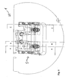
- eine Aufsicht auf eine erfindungsgemäße Formvorrichtung;
- Fig. 2
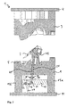
- eine Querschnittsansicht der Formvorrichtung aus
Fig. 1 in der Schnittebene A-A; - Fig. 3
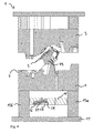
- eine Querschnittsansicht der Formvorrichtung aus
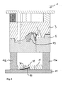
Fig. 1 in der Schnittebene B-B; - Fig. 4
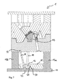
- eine Querschnittsansicht der Formvorrichtung aus
Fig. 1 in der Schnittebene C-C; - Fig. 5
- eine Aufsicht auf eine erfindungsgemäße Formvorrichtung in Spritzstellung;
- Fig. 6
- eine Querschnittsansicht der erfindungsgemäßen Formvorrichtung aus
Fig. 5 in der Schnittebene A-A; - Fig. 7
- eine Querschnittsansicht der Formvorrichtung aus
Fig. 5 in der Schnittebene B-B; - Fig. 8
- eine Querschnittsansicht der Formvorrichtung aus
Fig. 5 in der Schnittebene C-C; - Fig. 9
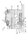
- eine weitere Querschnittsansicht der erfindungemäßen Formvorrichtung; und
- Fig.10
- eine weitere Querschnittsansicht der erfindungemäßen Formvorrichtung.
- Fig. 1
- a plan view of a molding device according to the invention;
- Fig. 2
- a cross-sectional view of the molding device
Fig. 1 in the section plane AA; - Fig. 3
- a cross-sectional view of the molding device
Fig. 1 in the section plane BB; - Fig. 4
- a cross-sectional view of the molding device
Fig. 1 in the sectional plane CC; - Fig. 5
- a plan view of a molding device according to the invention in the spray position;
- Fig. 6
- a cross-sectional view of the molding apparatus according to the invention
Fig. 5 in the section plane AA; - Fig. 7
- a cross-sectional view of the molding device
Fig. 5 in the section plane BB; - Fig. 8
- a cross-sectional view of the molding device
Fig. 5 in the sectional plane CC; - Fig. 9
- a further cross-sectional view of erfindungemäßen molding apparatus; and
- Figure 10
- a further cross-sectional view of erfindungemäßen molding device.
In der Folge verwendete Lagebezeichnungen, wie oben, unten, vorne, hinten, rechts und links, beziehen sich aus der Sicht eines Betrachters auf eine vor ihm angeordnete Formvorrichtung, wobei der Betrachter auf eine Seitenfläche der Formvorrichtung schaut.Sequence designations used hereafter, such as top, bottom, front, back, right and left, refer to a molding apparatus disposed in front of it as seen by a viewer, with the viewer looking at a side surface of the molding apparatus.
In den
Die erfindungsgemäße Formvorrichtung 1 umfasst zwei Formelemente, ein Formoberteil 3 und ein Formunterteil 5, die aus beliebigen Materialien hergestellt sein können. Zur Herstellung von kleineren Serien herzustellender Gegenstände können die Formteile beispielsweise aus Aluminium bestehen. Zur Herstellung von größeren Serien sind jedoch das Formoberteil 3 und das Formunterteil 5 üblicherweise aus Stahl gefertigt. Um den Verschleiß des Formoberteils 3 und Formunterteils 5 zu reduzieren, kann gehärteter oder vergüteter Werkzeugstahl und/oder Hartmetall verwendet werden. In den Innenseiten des Formoberteils 3 und des Formunterteils 5 sind mit Hilfe von Werkzeugmaschinen die Formkonturen nach Art eines Negativabdrucks eingearbeitet. Diese Konturen bestimmen die Form und die entsprechende Struktur eines zu fertigenden Gegenstandes 2.The
Die Formvorrichtung 1 kann beispielsweise beim Spritzgussverfahren zur Herstellung von Produkten aus Kunststoff oder im Druckgussverfahren für die Herstellung von metallischen Produkten Verwendung finden.The
Bei der in den
Zum Einleiten der Formmaterialmasse ist ein nicht gezeigtes Angussvorrichtung vorgesehen. Angussvorrichtungen sind bekannt und haben wesentlichen Einfluss auf die Spritzqualität oder Einpressqualität eines herzustellenden Gegenstandes 2. Oftmals wird die Schmelze über beheizte Kanalzuführungen, so genannte Heißkanäle, dem Hohlraum zugeleitet. Entscheidend für die Qualität der herzustellenden bzw. hergestellten Gegenstände sind ein konstanter Druck sowie eine konstante Temperatur, um den Hohlraum gleichmäßig auszufüllen.For introducing the molding material mass, a gate device, not shown, is provided. Sprue devices are known and have a significant influence on the spray quality or Einpressqualität an article to be produced 2. Often, the melt via heated channel feeders, called hot runners, fed to the cavity. Decisive for the quality of the articles to be produced or produced are a constant pressure and a constant temperature in order to fill the cavity uniformly.
Zum Einspritzen bzw. Einpressen von erwärmtem Formmaterial können sowohl das Formoberteil 3 als auch das Formunterteil 5 Durchlässe (nicht gezeigt) umfassen. Dabei kann das Einspritzen des erwärmten Formmaterials über in den Durchlässen ausgebildeten Düsen zeitgleich oder aber auch zeitversetzt erfolgen. Mit zeitversetzten Verfahren lassen sich vorteilhaft gleichmäßige Gegenstände bilden.For injecting or pressing in heated molding material, both the
Um den hergestellten Gegenstand 2 aus der Form entnehmen zu können, muss dieser zunächst erhärten bzw. erstarren. Je nach Beschaffenheit des Materials erfolgt dies entweder durch Erkalten oder über eine Wärmebehandlung.In order to remove the manufactured
Das Formunterteil 5 kann einstückig ausgebildet sein oder aber auf einer Formplatte 9 aufgesetzt und mit dieser gekoppelt, beispielsweise verspannt sein. Ebenso kann das Formoberteil 3 mit einer Spannplatte 4 verspannt sein. Das Formunterteil 5 oder die Formplatte 9 sind über Distanzleisten 13a und 13b mit einer Aufspannplatte 11 verbunden oder gekoppelt. Die Distanzleisten 13a und 13b können einstückig mit dem Formunterteil 5 und/oder der Aufspannplatte 11 ausgebildet sein. Alternativ können Distanzleisten 13a und 13b als flexible Elemente eingesetzt werden und mit der Aufspannplatte 11 und/oder dem Formunterteil 5 bzw. der Formplatte 9 beliebig geeignet verbunden sein. Zumeist sind die Distanzleisten 13a und 13b mit der Formplatte 9 bzw. dem Formunterteil 5 und/oder der Aufspannplatte 11 verschraubt oder verspannt. Die Aufspannung der Formhälften 3, 5 und der Formvorrichtung 1 können auch mittels Spannpratzen erfolgen.The
Zusätzlich sind die Formplatte 9 und/oder die Aufspannplatte 11 zur Aufspannung oftmals mit sogenannten Spannnuten (nicht gezeigt) versehen, in die die Distanzleisten 13a, b nach Art einer Nut-Feder-Führung eingeschoben werden. Solche Spannnuten ermöglichen vorteilhaft einen schnellen Wechsel der Formen und somit auch einen schnellen Wechsel der herzustellenden Gegenstände.In addition, the mold plate 9 and / or the clamping
Eine Öffnungs/Schließvorrichtung (nicht gezeigt) öffnet und schließt die Formelemente 3 und 5 beispielsweise über einen pneumatischen, hydraulischen oder elektrisch betätigten Hubmechanismus.An opening / closing device (not shown) opens and closes the
Zwischen den Distanzleisten 13a und 13b sowie zwischen der Formplatte 9 und der Aufspannplatte 11 ist ein plattenförmiges Auswerfelement, eine so genannte Auswerferplatte 15, angeordnet. Die Auswerferplatte 15 dient zum Ausfahren beziehungsweise zum Ausstoßen eines hergestellten Gegenstandes 2 aus der Formhälfte 5 mittels eines Kopplungselementes 19. Dazu ist die Auswerferplatte 15 höhenverschiebbar ausgebildet. Die Auswerferplatte 15 kann direkt über einen Hydraulikzylinder oder auch einen pneumatischen Mechanismus (nicht gezeigt) oder auch elektrisch bewegt werden. Auch kann die Auswerferplatte 15 über die Formvorrichtung 1 und/oder die Öffnungs/Schließvorrichtung angetrieben werden.Between the spacer strips 13a and 13b and between the mold plate 9 and the
In der geschlossenen Stellung ist über eine Formschlusshydraulik (nicht gezeigt) das Formoberteil 3 gegenüber dem Formunterteil 5 verschlossen. Zusätzlich kann eine Vorrichtung (nicht gezeigt), zum Zuhalten der Formteile, beispielsweise eine Hydraulik, vorgesehen sein. Somit sind eine Schließkraft zum Schließen der Formelemente 3, 5 sowie eine Haltekraft bereitgestellt, die das Formoberteil 3 und das Formunterteil 5 beim Einspritzen der Formmasse gegen den Spritz- oder Gussdruck zuhält. Der Spritzdruck wird dabei weitgehend von der Formplatte 9 abgefangen.In the closed position, the form
In der Spritzstellung liegt die Auswerferplatte 15 auf der Aufspannplatte 11 vollflächig auf (vgl.
Ferner kann die Formvorrichtung 1 neben einem Schieberkopf 43 eine zusätzliche Ausstoßvorrichtung (nicht gezeigt) zum Ausstoßen und/oder Auswerfen eines gespritzten oder gegossenen Gegenstandes 2 aufweisen. Dazu können beispielsweise Ausstoßbolzen im Schieberkopf 43 und oder in dem Formunterteil 5 vorgesehen sein, die einen erstarrten Gegenstand 2 aus dem Formunterteil 5 ausstoßen.Further, the
Weiter sind in der Formvorrichtung 1 ein erstes Führungselement 16 und ein zweites Führungselement 17 angeordnet. Das erste Führungselement ist als Führungsplatte 16 ausgebildet und in einer Ausnehmung in der Auswerferplatte 15 verschiebbar angeordnet. Das zweite Führungselement 17 ist als starre Führungspinole ausgebildet.Further, in the
Die Führungsplatte 16 wird über die Führungspinole 17 beim Betätigen der Auswerferplatte 16 zwangsgeführt. Wenn die Auswerferplatte 15 die Führungsplatte 16 nach oben verschiebt oder nach unten führt, wird die Führungsplatte 16 entlang der Führungspinole 17 nach oben geschoben oder nach unten bewegt und/oder abgebremst. Dabei wird die Führungsplatte 16 auch seitlich versetzt, entweder beim Anheben der Auswerferplatte 16 nach links oder beim Absenken der Auswerferplatte 16 nach rechts.The
In der in
Ferner sind in der Ausnehmung der Auswerferplatte 15 jeweils beidseitig Führungsleisten oder Führungsschienen 29 zur Führung der Führungsplatte 16 angeordnet. Die Führungsschienen 29 können mit der Auswerferplatte 15 beliebig geeignet verbunden sein. Als vorteilhaft hat sich ein Verschrauben der Führungsleiste mit der Auswerferplatte 15 erwiesen. Auch können die Führungsleisten 29 seitlich mit der Führungsplatte 16 verschweißt oder anders verbunden werden. Alternativ können sie auch einstückig an der Führungsplatte 16 ausgebildet sein. Innerhalb der Führungsleisten 29 ist die Führungsplatte 16 verschiebbar gelagert,Furthermore, in each case guide rails or
Dazu umfassen die Führungsleisten 29 jeweils eine Ausnehmung, beispielsweise Führungsnuten, die mit der Führungsplatte 16 beispielsweise über eine an der Führungsplatte 16 ausgebildete Ausbildung 24, etwa eine Leiste, in Verbindung stehen. Die Führung erfolgt dann nach Art einer Nut Feder Führung.For this purpose, the guide rails 29 each comprise a recess, for example guide grooves, which are in communication with the
In einer geschlossenen Formvorrichtung 1 liegen die Führungsleisten 29 auf der Aufspannplatte 11 nahezu auf bzw. sind teilweise in einer in der Aufspannplatte 11 ausgebildeten Ausnehmung 33 aufgenommen (vgl.
In der in
Ferner ist die Führungspinole 17 am oberen Ende in einer Ausnehmung 22 der Formplatte 9 eingesetzt und verankert, beispielsweise verstiftet, verschraubt oder eingelassen. Die Führungspinole 17 verläuft schräg zur Längsachse der Formvorrichtung 1, wobei sie eine in der Führungsplatte 16 angeordnete Ausnehmung 27 durchdringt. An Ihrem unteren Ende ist die Führungspinole 17 in eine in der Aufspannplatte 11 ausgebildeten Ausnehmung 23 eingesetzt. In der Ausnehmung 23 ist das untere Ende der Führungspinole 17 mit der Aufspannplatte 11 fest verbunden, vorzugsweise verstiftet, verschraubt oder eingelassen.Further, the
Zusätzlich ist in der Formplatte 9 eine durchgängige Ausnehmung 21 ausgebildet, in der das Kopplungselement, die sogenannte Führungspinole 19, eingesetzt ist. Die Führungspinole 19 ist innerhalb der Ausnehmung 21 in Längsrichtung beweglich. Sowohl die Führungspinole 19 als auch die Ausnehmung 21 sind schräg zur Längsachse der Formvorrichtung 1 angeordnet und ausgebildet. Die Führungspinole 19 wird zusammen mit der Auswerferplatte 15 nach oben gefahren.In addition, a
Am oberen Ende der Führungspinole 19 ist der Schieberkopf 43 angeordnet. Der Schieberkopf 43 kann einstückig an der Führungspinole 19 ausgebildet sein oder über beliebige geeignete Befestigungsmittel (nicht gezeigt) mit der Führungspinole 19 verbunden sein, beispielsweise verschraubt. Alternativ kann die Führungspinole 19 auch eine Verbreiterung aufweisen, die auf einen hergestellten Gegenstand 2 wirkt.At the upper end of the
Bei Betätigung der Auswerferplatte 16 wird die Führungspinole 19 nach oben gefahren und der Schieberkopf 43 hebt den hergestellten Gegenstand 2 aus dem Formunterteil 5 nach oben, wobei der hergestellte Gegenstand 2 und/oder der Schieberkopf 43 über einen Teil oder den gesamten Öffnungsvorgang zur Hauptentformungsrichtung verzögert beziehungsweise beschleunigt. Dies erfolgt über die Verschiebung der Führungsplatte 16 und/oder eine nachfolgend beschriebene Verschiebung der Führungspinole 19 innerhalb der Auswerferplatte 15. Beim Absenken der Auswerferplatte 15 werden diese Bewegungen umgekehrt.Upon actuation of the
Der Schieberkopf 43 wird in der Spritzstellung komplett in wenigstens einem Formelement 3, 5, beispielsweise in einer Ausnehmung, aufgenommen und gehalten. Bei Betätigung der Auswerferplatte 15 wird der Schieberkopf 43 aus der Ausnehmung gefahren. Beim Auswerfen beziehungsweise beim Entformen des Gegenstandes 2 kann der Schieberkopf 43 mit diesem und/oder relativ zu dem Gegenstand 2 verschoben werden, um Hinterschnitte in Richtung der Hauptentformungsrichtung (senkrecht nach oben) zu Entformen. Der Schieberkopf 43 kann also zur Hauptentformungsrichtung verschwenkt werden. Dies wird als Verzögerung und/oder Beschleunigung des Schieberkopfes 43 bezeichnet. Erfindungsgemäß lassen sich nunmehr eine Verzögerung bzw. Beschleunigung von bis zu 180° zur Hauptentformungsrichtung beziehungsweise von bis zu 90° zur Auswurfplatte 15 erreichen.The
Weiter ist innerhalb der Führungspinole 19 ein Fluidkanal 41 ausgebildet. Am unteren Ende der Führungspinole 19 sind Fluideinlasse bzw. -auslasse 39 angeordnet. Der Fluidkanal 41 kann über die Fluideinlasse bzw. -auslasse 39 an einen in der Formvorrichtung 1 vorhandenen Kühlkreislauf angeschlossen werden. Darin ist ein beliebiges Kühlfluid einleitbar, um eine entsprechende Kühlung oder Erwärmung des herzustellenden Gegenstandes und/oder der Formelemente 3, 5 zu erreichen. Die Kühlung ist ein wesentlicher Faktor für den Produktionszyklus. Je stärker die Kühlung ausgelegt ist, desto eher lassen sich Zykluszeiten kürzen. Ein vollständiges Auskühlen eines zu fertigenden Gegenstandes 2 lässt sich beispielsweise innerhalb eines Zeitraums von 60 Sekunden erreichen.Further, a
Zusätzlich können auch innerhalb der Führungspinole 19 bzw. der Formteile 3 und 5 Heizvorrichtungen vorgesehen sein, um das Formmaterial in einem erwärmten Zustand zu halten. Auch kann es erforderlich sein, gegebenenfalls das Formoberteil 3 und/oder das Formunterteil 5 vor dem Einbringen einer Spritzguss- oder Druckgussmasse zunächst zu erwärmen. So verlaufen Fluidkanäle (nicht gezeigt) im Formoberteil 3 und Formunterteil 5 nahe zum Hohlraum. Ein solcher Fluidkreislauf kann die Lebensdauer der Formteile erhöhen und die Oberflächenbeschaffenheit der herzustellenden Gegenstände verbessern.In addition, heating devices can also be provided inside the
Am unteren Ende ist die Führungspinole 19 mit einer schuhartig ausgestalteten Führungseinheit 31 versehen. Die Führungseinheit 31 ist in einer kulissenartigen Führungseinrichtung seitlich verschiebbar, die innerhalb der Führungsplatte 16 angeordnet ist. Dazu ist in der Führungsplatte 16 eine Ausnehmung, insbesondere eine Führungsnut ausgebildet, in der die Führungseinheit 31 zum Verschieben geführt ist. Innerhalb der Führungseinheit 31 kann eine Gelenkverbindung zur Verbindung der Führungseinheit 31 mit der Führungspinolenstange angeordnet sein.At the lower end of the
Beim oder nach dem Öffnen der Formhälften 3, 5 aus der Spritzstellung oder geschlossenen Stellung in die Entnahmestellung wird die Auswerferplatte 15 betätigt und angehoben, so dass die Führungseinheit 31 innerhalb der Führung entlang der Führungsnuten nach rechts verschoben und beim Schließen nach links. In Abhängigkeit von der Anordnung und dem Aufbau der einzelnen Komponenten in der Formvorrichtung 1 sind hier auch beliebige geeignet andere Verschieberichtungen möglich.When or after opening the mold halves 3, 5 from the injection position or closed position into the removal position, the
Ferner sind das Kopplungselement 19 und die Führungspinole 19 entgegengesetzt zueinander angeordnet. Über diese entgegen gesetzte Schrägstellung wird die Zwangsführung der Führungsplatte 16 betätigt. Über den Versatz der Führungsplatte 16 und über den Versatz der Führungspinole 19 lassen sich hinterschnittige Geometrien eines gefertigten Gegenstandes 2 entformen.Furthermore, the
Beim Schließen der Formvorrichtung 1 aus der geöffneten Stellung in die Schließstellung erfolgen der zuvor beschriebene Öffnungsmechanismus und die Betätigung der Auswerfplatte 15 in umgekehrter Reihenfolge. Wenn das Formoberteil 3 auf dem Formunterteil 5 aufliegt, sind beide gegeneinander verschlossen und können verriegelt werden. Als geeigneter Verriegelungsmechanismus kann ein ausreichend starker Hydraulikzylinder vorgesehen sein.When closing the
Weitere Ausgestaltungen und Variationen der vorliegenden Erfindung ergeben sich für den Fachmann im Rahmen der nachfolgenden Patentansprüche.Further embodiments and variations of the present invention will become apparent to those skilled in the art within the scope of the following claims.
Claims (16)
das Kopplungselement (19) vom ersten Führungselement (16) geführt ist, und
im ersten Führungselement (16) eine Ausnehmung (27) ausgebildet ist, in die das zweite Führungselement (17) zur Bildung einer Zwangsführung einsetzbar ist.Forming device (1) for injection or pressure casting for the production of molded articles with
the coupling element (19) is guided by the first guide element (16), and
in the first guide element (16) a recess (27) is formed, in which the second guide element (17) can be used to form a positive guide.
Applications Claiming Priority (1)
| Application Number | Priority Date | Filing Date | Title |
|---|---|---|---|
| DE102009037981A DE102009037981B3 (en) | 2009-08-19 | 2009-08-19 | Shaping device and method for demolding an object |
Publications (2)
| Publication Number | Publication Date |
|---|---|
| EP2286974A1 true EP2286974A1 (en) | 2011-02-23 |
| EP2286974B1 EP2286974B1 (en) | 2012-11-07 |
Family
ID=43035014
Family Applications (1)
| Application Number | Title | Priority Date | Filing Date |
|---|---|---|---|
| EP10008688A Not-in-force EP2286974B1 (en) | 2009-08-19 | 2010-08-19 | Forming device and method for removing an object |
Country Status (3)
| Country | Link |
|---|---|
| EP (1) | EP2286974B1 (en) |
| DE (1) | DE102009037981B3 (en) |
| PT (1) | PT2286974E (en) |
Cited By (9)
| Publication number | Priority date | Publication date | Assignee | Title |
|---|---|---|---|---|
| CN102814483A (en) * | 2012-05-31 | 2012-12-12 | 昆山拓安塑料制品有限公司 | Overlong thin-rib ladder type LED (light-emitting diode) supporting frame aluminum alloy die-casting die |
| CN102873838A (en) * | 2012-09-25 | 2013-01-16 | 宁波方正汽车模具有限公司 | Angle ejector rod with stress step |
| FR3037849A1 (en) * | 2015-06-26 | 2016-12-30 | Faurecia Interieur Ind | EJECTION DEVICE FOR A TOOL FOR MAKING A FORMED PART |
| WO2017218091A1 (en) * | 2016-06-13 | 2017-12-21 | Progressive Components International Corporation | Molded undercut release apparatus |
| CN107838397A (en) * | 2017-12-11 | 2018-03-27 | 江苏中翼汽车新材料科技有限公司 | A kind of slide block thimble mechanism of compression mod |
| EP2933084B1 (en) * | 2014-04-17 | 2019-04-10 | Joachim Thielke | Mould with mouldcomponents that are floating and protected against torsion. |
| EP3708332A1 (en) * | 2019-03-13 | 2020-09-16 | Comercial de Utiles y Moldes, S.A. | Device for demoulding negatives in thermoplastic injection moulds |
| IT201900025219A1 (en) * | 2019-12-23 | 2021-06-23 | Adm S R L Start Up Innovativa | SABER FOR THERMOPLASTIC MOLDS |
| CN113828755A (en) * | 2021-10-27 | 2021-12-24 | 马伟明 | Ejection mechanism of secondary ejection die-casting die |
Families Citing this family (2)
| Publication number | Priority date | Publication date | Assignee | Title |
|---|---|---|---|---|
| DE102013000320B4 (en) * | 2013-01-10 | 2018-10-31 | Audi Ag | Tooling device for the production of a cast component |
| DE102013114937B4 (en) | 2013-12-30 | 2017-10-05 | Ksm Castings Group Gmbh | Ejecting device and method for demolding a casting from a casting device |
Citations (5)
| Publication number | Priority date | Publication date | Assignee | Title |
|---|---|---|---|---|
| DE4203696C2 (en) | 1992-02-08 | 1994-05-26 | Theysohn Friedrich Fa | Device for injection molding a molded part made of plastic |
| JPH08238652A (en) * | 1995-03-02 | 1996-09-17 | Sekisui Chem Co Ltd | Injection mold |
| DE10022192A1 (en) | 2000-05-03 | 2001-11-15 | Mannesmann Ag | Device for removing injection molded parts |
| ES2238881A1 (en) * | 2002-04-16 | 2005-09-01 | Troqueles Y Modes De Galicia, S.A. (Tromosa) | Plastics injection mould inclined runner guide shoe includes a rotating head and a reinforcing column also free to rotate |
| US7140868B1 (en) * | 2003-10-27 | 2006-11-28 | Hs Die & Engineering, Inc. | Universal lifter foot assembly for removal of core block from mold |
-
2009
- 2009-08-19 DE DE102009037981A patent/DE102009037981B3/en not_active Expired - Fee Related
-
2010
- 2010-08-19 EP EP10008688A patent/EP2286974B1/en not_active Not-in-force
- 2010-08-19 PT PT100086883T patent/PT2286974E/en unknown
Patent Citations (5)
| Publication number | Priority date | Publication date | Assignee | Title |
|---|---|---|---|---|
| DE4203696C2 (en) | 1992-02-08 | 1994-05-26 | Theysohn Friedrich Fa | Device for injection molding a molded part made of plastic |
| JPH08238652A (en) * | 1995-03-02 | 1996-09-17 | Sekisui Chem Co Ltd | Injection mold |
| DE10022192A1 (en) | 2000-05-03 | 2001-11-15 | Mannesmann Ag | Device for removing injection molded parts |
| ES2238881A1 (en) * | 2002-04-16 | 2005-09-01 | Troqueles Y Modes De Galicia, S.A. (Tromosa) | Plastics injection mould inclined runner guide shoe includes a rotating head and a reinforcing column also free to rotate |
| US7140868B1 (en) * | 2003-10-27 | 2006-11-28 | Hs Die & Engineering, Inc. | Universal lifter foot assembly for removal of core block from mold |
Cited By (17)
| Publication number | Priority date | Publication date | Assignee | Title |
|---|---|---|---|---|
| CN102814483B (en) * | 2012-05-31 | 2015-04-29 | 昆山拓安塑料制品有限公司 | Overlong thin-rib ladder type LED (light-emitting diode) supporting frame aluminum alloy die-casting die |
| CN102814483A (en) * | 2012-05-31 | 2012-12-12 | 昆山拓安塑料制品有限公司 | Overlong thin-rib ladder type LED (light-emitting diode) supporting frame aluminum alloy die-casting die |
| CN102873838A (en) * | 2012-09-25 | 2013-01-16 | 宁波方正汽车模具有限公司 | Angle ejector rod with stress step |
| CN102873838B (en) * | 2012-09-25 | 2014-12-17 | 宁波方正汽车模具有限公司 | Angle ejector rod with stress step |
| EP2933084B1 (en) * | 2014-04-17 | 2019-04-10 | Joachim Thielke | Mould with mouldcomponents that are floating and protected against torsion. |
| FR3037849A1 (en) * | 2015-06-26 | 2016-12-30 | Faurecia Interieur Ind | EJECTION DEVICE FOR A TOOL FOR MAKING A FORMED PART |
| US10220556B2 (en) | 2016-06-13 | 2019-03-05 | Progressive Components International Corporation | Molded undercut release apparatus |
| WO2017218091A1 (en) * | 2016-06-13 | 2017-12-21 | Progressive Components International Corporation | Molded undercut release apparatus |
| EP3842210A1 (en) * | 2016-06-13 | 2021-06-30 | Progressive Components International Corporation | Core lifter apparatus |
| CN107838397A (en) * | 2017-12-11 | 2018-03-27 | 江苏中翼汽车新材料科技有限公司 | A kind of slide block thimble mechanism of compression mod |
| CN107838397B (en) * | 2017-12-11 | 2023-08-11 | 江苏中翼汽车新材料科技有限公司 | Slider thimble mechanism of die-casting mould |
| EP3708332A1 (en) * | 2019-03-13 | 2020-09-16 | Comercial de Utiles y Moldes, S.A. | Device for demoulding negatives in thermoplastic injection moulds |
| US11345070B2 (en) | 2019-03-13 | 2022-05-31 | Comercial De Utiles Y Moldes, S.A. | Device for demoulding negatives in thermoplastic injection moulds |
| IT201900025219A1 (en) * | 2019-12-23 | 2021-06-23 | Adm S R L Start Up Innovativa | SABER FOR THERMOPLASTIC MOLDS |
| WO2021130633A1 (en) * | 2019-12-23 | 2021-07-01 | Adm S.R.L. Start Up Innovativa | Saber-like element for thermoplastic molds |
| CN113828755A (en) * | 2021-10-27 | 2021-12-24 | 马伟明 | Ejection mechanism of secondary ejection die-casting die |
| CN113828755B (en) * | 2021-10-27 | 2023-10-27 | 苏可森(天门)模塑科技有限公司 | Ejection mechanism of secondary ejection die casting die |
Also Published As
| Publication number | Publication date |
|---|---|
| PT2286974E (en) | 2013-01-04 |
| DE102009037981B3 (en) | 2011-03-03 |
| EP2286974B1 (en) | 2012-11-07 |
Similar Documents
| Publication | Publication Date | Title |
|---|---|---|
| EP2286974B1 (en) | Forming device and method for removing an object | |
| EP2015918B1 (en) | Injection-molding installation for producing proliferated, elongated parts | |
| DE102005011311B3 (en) | Injection molding tool for forming undercut moldings has retractable slide connected to retacting guide so that slide moves along the axes of demolding guide and retraction guide | |
| EP1813404A2 (en) | Moulding tool | |
| WO2007096144A2 (en) | Process for production of thin-walled plastics mouldings | |
| EP0074473A1 (en) | Method of and apparatus for manufacturing moulded plastics pieces or articles | |
| DE102014012416B3 (en) | TOOL FOR THE POISONING OF COMPONENTS AND MANUFACTURING METHOD FOR INJECTION MOLDING PARTS | |
| WO2013072459A2 (en) | Locking device for pillars of a plastics processing machine | |
| EP4076897A1 (en) | Tool and method for injection moulding an injection-moulded part in a tool | |
| DE102007002298B4 (en) | Apparatus and method for producing a molded part | |
| EP3117977B1 (en) | Tool half for a mould of an injection moulding machine with a hot runner system | |
| EP1690665A1 (en) | Process and injection mould for manufacturing a plastic strip | |
| EP2134528B1 (en) | Moulding tool with a modular construction comprising a frame | |
| EP1787784A1 (en) | Mould for manufacturing parts by injection moulding, pressure die casting or a deposition method | |
| WO2017017175A1 (en) | Injection-moulding machine with multi-daylight mould for injection-compression moulding applications and injection-compression moulding process | |
| WO2018172128A1 (en) | Method and device for producing components or profiles | |
| EP1804995B1 (en) | Method for injection stamping a thermoplastic material | |
| DE2064670A1 (en) | Injection molding machine for processing in particular heat-crosslinkable plastics or the like | |
| DE1779267C3 (en) | Injection mold for the production of two-tone injection molded parts | |
| DE102008056670B4 (en) | Method for operating an injection molding device | |
| DE202016106485U1 (en) | Injection molding machine and plates for placement in an injection molding machine | |
| EP2556942B1 (en) | Injection moulding method and injection moulding tool, in particular jaw tool | |
| DE202005016752U1 (en) | Injection moulding tool for plastic materials comprises at least two mould inserts separated by one or more intermediate contour plates | |
| EP2556917A2 (en) | Tool and use of same in an injection moulding machine | |
| DE102005047266A1 (en) | Making plastic articles by injection stamping comprises using a stamp whose size and travel are sufficient to generate the necessary melt pressure to completely fill the mold cavity after stamp insertion |
Legal Events
| Date | Code | Title | Description |
|---|---|---|---|
| PUAI | Public reference made under article 153(3) epc to a published international application that has entered the european phase |
Free format text: ORIGINAL CODE: 0009012 |
|
| AK | Designated contracting states |
Kind code of ref document: A1 Designated state(s): AL AT BE BG CH CY CZ DE DK EE ES FI FR GB GR HR HU IE IS IT LI LT LU LV MC MK MT NL NO PL PT RO SE SI SK SM TR |
|
| AX | Request for extension of the european patent |
Extension state: BA ME RS |
|
| 17P | Request for examination filed |
Effective date: 20110720 |
|
| RIC1 | Information provided on ipc code assigned before grant |
Ipc: B29C 43/50 20060101ALI20120229BHEP Ipc: B29C 43/42 20060101ALI20120229BHEP Ipc: B29C 45/44 20060101ALI20120229BHEP Ipc: B22D 17/22 20060101ALI20120229BHEP Ipc: B29C 33/48 20060101AFI20120229BHEP |
|
| GRAP | Despatch of communication of intention to grant a patent |
Free format text: ORIGINAL CODE: EPIDOSNIGR1 |
|
| GRAS | Grant fee paid |
Free format text: ORIGINAL CODE: EPIDOSNIGR3 |
|
| GRAA | (expected) grant |
Free format text: ORIGINAL CODE: 0009210 |
|
| AK | Designated contracting states |
Kind code of ref document: B1 Designated state(s): AL AT BE BG CH CY CZ DE DK EE ES FI FR GB GR HR HU IE IS IT LI LT LU LV MC MK MT NL NO PL PT RO SE SI SK SM TR |
|
| REG | Reference to a national code |
Ref country code: GB Ref legal event code: FG4D Free format text: NOT ENGLISH |
|
| REG | Reference to a national code |
Ref country code: AT Ref legal event code: REF Ref document number: 582797 Country of ref document: AT Kind code of ref document: T Effective date: 20121115 Ref country code: CH Ref legal event code: EP |
|
| REG | Reference to a national code |
Ref country code: IE Ref legal event code: FG4D Free format text: LANGUAGE OF EP DOCUMENT: GERMAN |
|
| REG | Reference to a national code |
Ref country code: DE Ref legal event code: R096 Ref document number: 502010001575 Country of ref document: DE Effective date: 20130103 |
|
| REG | Reference to a national code |
Ref country code: PT Ref legal event code: SC4A Free format text: AVAILABILITY OF NATIONAL TRANSLATION Effective date: 20121213 |
|
| REG | Reference to a national code |
Ref country code: NL Ref legal event code: VDEP Effective date: 20121107 |
|
| REG | Reference to a national code |
Ref country code: LT Ref legal event code: MG4D |
|
| PG25 | Lapsed in a contracting state [announced via postgrant information from national office to epo] |
Ref country code: NO Free format text: LAPSE BECAUSE OF FAILURE TO SUBMIT A TRANSLATION OF THE DESCRIPTION OR TO PAY THE FEE WITHIN THE PRESCRIBED TIME-LIMIT Effective date: 20130207 Ref country code: IS Free format text: LAPSE BECAUSE OF FAILURE TO SUBMIT A TRANSLATION OF THE DESCRIPTION OR TO PAY THE FEE WITHIN THE PRESCRIBED TIME-LIMIT Effective date: 20130307 Ref country code: SE Free format text: LAPSE BECAUSE OF FAILURE TO SUBMIT A TRANSLATION OF THE DESCRIPTION OR TO PAY THE FEE WITHIN THE PRESCRIBED TIME-LIMIT Effective date: 20121107 Ref country code: NL Free format text: LAPSE BECAUSE OF FAILURE TO SUBMIT A TRANSLATION OF THE DESCRIPTION OR TO PAY THE FEE WITHIN THE PRESCRIBED TIME-LIMIT Effective date: 20121107 Ref country code: HR Free format text: LAPSE BECAUSE OF FAILURE TO SUBMIT A TRANSLATION OF THE DESCRIPTION OR TO PAY THE FEE WITHIN THE PRESCRIBED TIME-LIMIT Effective date: 20121107 Ref country code: FI Free format text: LAPSE BECAUSE OF FAILURE TO SUBMIT A TRANSLATION OF THE DESCRIPTION OR TO PAY THE FEE WITHIN THE PRESCRIBED TIME-LIMIT Effective date: 20121107 Ref country code: LT Free format text: LAPSE BECAUSE OF FAILURE TO SUBMIT A TRANSLATION OF THE DESCRIPTION OR TO PAY THE FEE WITHIN THE PRESCRIBED TIME-LIMIT Effective date: 20121107 |
|
| PG25 | Lapsed in a contracting state [announced via postgrant information from national office to epo] |
Ref country code: SI Free format text: LAPSE BECAUSE OF FAILURE TO SUBMIT A TRANSLATION OF THE DESCRIPTION OR TO PAY THE FEE WITHIN THE PRESCRIBED TIME-LIMIT Effective date: 20121107 Ref country code: LV Free format text: LAPSE BECAUSE OF FAILURE TO SUBMIT A TRANSLATION OF THE DESCRIPTION OR TO PAY THE FEE WITHIN THE PRESCRIBED TIME-LIMIT Effective date: 20121107 Ref country code: GR Free format text: LAPSE BECAUSE OF FAILURE TO SUBMIT A TRANSLATION OF THE DESCRIPTION OR TO PAY THE FEE WITHIN THE PRESCRIBED TIME-LIMIT Effective date: 20130208 Ref country code: PL Free format text: LAPSE BECAUSE OF FAILURE TO SUBMIT A TRANSLATION OF THE DESCRIPTION OR TO PAY THE FEE WITHIN THE PRESCRIBED TIME-LIMIT Effective date: 20121107 |
|
| PG25 | Lapsed in a contracting state [announced via postgrant information from national office to epo] |
Ref country code: CZ Free format text: LAPSE BECAUSE OF FAILURE TO SUBMIT A TRANSLATION OF THE DESCRIPTION OR TO PAY THE FEE WITHIN THE PRESCRIBED TIME-LIMIT Effective date: 20121107 Ref country code: EE Free format text: LAPSE BECAUSE OF FAILURE TO SUBMIT A TRANSLATION OF THE DESCRIPTION OR TO PAY THE FEE WITHIN THE PRESCRIBED TIME-LIMIT Effective date: 20121107 Ref country code: SK Free format text: LAPSE BECAUSE OF FAILURE TO SUBMIT A TRANSLATION OF THE DESCRIPTION OR TO PAY THE FEE WITHIN THE PRESCRIBED TIME-LIMIT Effective date: 20121107 Ref country code: DK Free format text: LAPSE BECAUSE OF FAILURE TO SUBMIT A TRANSLATION OF THE DESCRIPTION OR TO PAY THE FEE WITHIN THE PRESCRIBED TIME-LIMIT Effective date: 20121107 Ref country code: BG Free format text: LAPSE BECAUSE OF FAILURE TO SUBMIT A TRANSLATION OF THE DESCRIPTION OR TO PAY THE FEE WITHIN THE PRESCRIBED TIME-LIMIT Effective date: 20130207 |
|
| PG25 | Lapsed in a contracting state [announced via postgrant information from national office to epo] |
Ref country code: RO Free format text: LAPSE BECAUSE OF FAILURE TO SUBMIT A TRANSLATION OF THE DESCRIPTION OR TO PAY THE FEE WITHIN THE PRESCRIBED TIME-LIMIT Effective date: 20121107 |
|
| PLBE | No opposition filed within time limit |
Free format text: ORIGINAL CODE: 0009261 |
|
| STAA | Information on the status of an ep patent application or granted ep patent |
Free format text: STATUS: NO OPPOSITION FILED WITHIN TIME LIMIT |
|
| 26N | No opposition filed |
Effective date: 20130808 |
|
| PG25 | Lapsed in a contracting state [announced via postgrant information from national office to epo] |
Ref country code: ES Free format text: LAPSE BECAUSE OF FAILURE TO SUBMIT A TRANSLATION OF THE DESCRIPTION OR TO PAY THE FEE WITHIN THE PRESCRIBED TIME-LIMIT Effective date: 20130218 |
|
| PG25 | Lapsed in a contracting state [announced via postgrant information from national office to epo] |
Ref country code: CY Free format text: LAPSE BECAUSE OF FAILURE TO SUBMIT A TRANSLATION OF THE DESCRIPTION OR TO PAY THE FEE WITHIN THE PRESCRIBED TIME-LIMIT Effective date: 20121107 |
|
| REG | Reference to a national code |
Ref country code: DE Ref legal event code: R097 Ref document number: 502010001575 Country of ref document: DE Effective date: 20130808 |
|
| BERE | Be: lapsed |
Owner name: CHRISTIAN KARL SIEBENWURST MODELLFABRIK UND FORME Effective date: 20130831 |
|
| PG25 | Lapsed in a contracting state [announced via postgrant information from national office to epo] |
Ref country code: MC Free format text: LAPSE BECAUSE OF FAILURE TO SUBMIT A TRANSLATION OF THE DESCRIPTION OR TO PAY THE FEE WITHIN THE PRESCRIBED TIME-LIMIT Effective date: 20121107 |
|
| REG | Reference to a national code |
Ref country code: IE Ref legal event code: MM4A |
|
| PG25 | Lapsed in a contracting state [announced via postgrant information from national office to epo] |
Ref country code: BE Free format text: LAPSE BECAUSE OF NON-PAYMENT OF DUE FEES Effective date: 20130831 |
|
| PG25 | Lapsed in a contracting state [announced via postgrant information from national office to epo] |
Ref country code: IE Free format text: LAPSE BECAUSE OF NON-PAYMENT OF DUE FEES Effective date: 20130819 |
|
| REG | Reference to a national code |
Ref country code: CH Ref legal event code: PL |
|
| GBPC | Gb: european patent ceased through non-payment of renewal fee |
Effective date: 20140819 |
|
| PG25 | Lapsed in a contracting state [announced via postgrant information from national office to epo] |
Ref country code: LI Free format text: LAPSE BECAUSE OF NON-PAYMENT OF DUE FEES Effective date: 20140831 Ref country code: CH Free format text: LAPSE BECAUSE OF NON-PAYMENT OF DUE FEES Effective date: 20140831 |
|
| PG25 | Lapsed in a contracting state [announced via postgrant information from national office to epo] |
Ref country code: SM Free format text: LAPSE BECAUSE OF FAILURE TO SUBMIT A TRANSLATION OF THE DESCRIPTION OR TO PAY THE FEE WITHIN THE PRESCRIBED TIME-LIMIT Effective date: 20121107 |
|
| PG25 | Lapsed in a contracting state [announced via postgrant information from national office to epo] |
Ref country code: MT Free format text: LAPSE BECAUSE OF FAILURE TO SUBMIT A TRANSLATION OF THE DESCRIPTION OR TO PAY THE FEE WITHIN THE PRESCRIBED TIME-LIMIT Effective date: 20121107 Ref country code: TR Free format text: LAPSE BECAUSE OF FAILURE TO SUBMIT A TRANSLATION OF THE DESCRIPTION OR TO PAY THE FEE WITHIN THE PRESCRIBED TIME-LIMIT Effective date: 20121107 |
|
| PG25 | Lapsed in a contracting state [announced via postgrant information from national office to epo] |
Ref country code: GB Free format text: LAPSE BECAUSE OF NON-PAYMENT OF DUE FEES Effective date: 20140819 Ref country code: HU Free format text: LAPSE BECAUSE OF FAILURE TO SUBMIT A TRANSLATION OF THE DESCRIPTION OR TO PAY THE FEE WITHIN THE PRESCRIBED TIME-LIMIT; INVALID AB INITIO Effective date: 20100819 Ref country code: LU Free format text: LAPSE BECAUSE OF NON-PAYMENT OF DUE FEES Effective date: 20130819 Ref country code: MK Free format text: LAPSE BECAUSE OF FAILURE TO SUBMIT A TRANSLATION OF THE DESCRIPTION OR TO PAY THE FEE WITHIN THE PRESCRIBED TIME-LIMIT Effective date: 20121107 |
|
| REG | Reference to a national code |
Ref country code: FR Ref legal event code: PLFP Year of fee payment: 6 |
|
| REG | Reference to a national code |
Ref country code: PT Ref legal event code: MM4A Free format text: LAPSE DUE TO NON-PAYMENT OF FEES Effective date: 20160219 |
|
| REG | Reference to a national code |
Ref country code: PT Ref legal event code: NF4A Free format text: RESTITUTIO IN INTEGRUM Effective date: 20160229 |
|
| PG25 | Lapsed in a contracting state [announced via postgrant information from national office to epo] |
Ref country code: PT Free format text: LAPSE BECAUSE OF NON-PAYMENT OF DUE FEES Effective date: 20160219 |
|
| REG | Reference to a national code |
Ref country code: FR Ref legal event code: PLFP Year of fee payment: 7 |
|
| REG | Reference to a national code |
Ref country code: AT Ref legal event code: MM01 Ref document number: 582797 Country of ref document: AT Kind code of ref document: T Effective date: 20150819 |
|
| PG25 | Lapsed in a contracting state [announced via postgrant information from national office to epo] |
Ref country code: AT Free format text: LAPSE BECAUSE OF NON-PAYMENT OF DUE FEES Effective date: 20150819 |
|
| REG | Reference to a national code |
Ref country code: FR Ref legal event code: PLFP Year of fee payment: 8 |
|
| REG | Reference to a national code |
Ref country code: FR Ref legal event code: PLFP Year of fee payment: 9 |
|
| PG25 | Lapsed in a contracting state [announced via postgrant information from national office to epo] |
Ref country code: AL Free format text: LAPSE BECAUSE OF FAILURE TO SUBMIT A TRANSLATION OF THE DESCRIPTION OR TO PAY THE FEE WITHIN THE PRESCRIBED TIME-LIMIT Effective date: 20121107 |
|
| PGFP | Annual fee paid to national office [announced via postgrant information from national office to epo] |
Ref country code: PT Payment date: 20190906 Year of fee payment: 10 Ref country code: IT Payment date: 20190828 Year of fee payment: 10 Ref country code: FR Payment date: 20190829 Year of fee payment: 10 |
|
| PGFP | Annual fee paid to national office [announced via postgrant information from national office to epo] |
Ref country code: DE Payment date: 20191029 Year of fee payment: 10 |
|
| REG | Reference to a national code |
Ref country code: DE Ref legal event code: R119 Ref document number: 502010001575 Country of ref document: DE |
|
| PG25 | Lapsed in a contracting state [announced via postgrant information from national office to epo] |
Ref country code: PT Free format text: LAPSE BECAUSE OF NON-PAYMENT OF DUE FEES Effective date: 20210322 |
|
| PG25 | Lapsed in a contracting state [announced via postgrant information from national office to epo] |
Ref country code: IT Free format text: LAPSE BECAUSE OF NON-PAYMENT OF DUE FEES Effective date: 20200819 Ref country code: FR Free format text: LAPSE BECAUSE OF NON-PAYMENT OF DUE FEES Effective date: 20200831 Ref country code: DE Free format text: LAPSE BECAUSE OF NON-PAYMENT OF DUE FEES Effective date: 20210302 |