EP2286490B1 - End cap, socket, and adaptors for use with a lamp - Google Patents
End cap, socket, and adaptors for use with a lamp Download PDFInfo
- Publication number
- EP2286490B1 EP2286490B1 EP09794887.1A EP09794887A EP2286490B1 EP 2286490 B1 EP2286490 B1 EP 2286490B1 EP 09794887 A EP09794887 A EP 09794887A EP 2286490 B1 EP2286490 B1 EP 2286490B1
- Authority
- EP
- European Patent Office
- Prior art keywords
- key
- socket
- end cap
- groove
- face
- Prior art date
- Legal status (The legal status is an assumption and is not a legal conclusion. Google has not performed a legal analysis and makes no representation as to the accuracy of the status listed.)
- Active
Links
Images
























Classifications
-
- H—ELECTRICITY
- H01—ELECTRIC ELEMENTS
- H01R—ELECTRICALLY-CONDUCTIVE CONNECTIONS; STRUCTURAL ASSOCIATIONS OF A PLURALITY OF MUTUALLY-INSULATED ELECTRICAL CONNECTING ELEMENTS; COUPLING DEVICES; CURRENT COLLECTORS
- H01R33/00—Coupling devices specially adapted for supporting apparatus and having one part acting as a holder providing support and electrical connection via a counterpart which is structurally associated with the apparatus, e.g. lamp holders; Separate parts thereof
- H01R33/05—Two-pole devices
- H01R33/06—Two-pole devices with two current-carrying pins, blades or analogous contacts, having their axes parallel to each other
- H01R33/08—Two-pole devices with two current-carrying pins, blades or analogous contacts, having their axes parallel to each other for supporting tubular fluorescent lamp
- H01R33/0836—Two-pole devices with two current-carrying pins, blades or analogous contacts, having their axes parallel to each other for supporting tubular fluorescent lamp characterised by the lamp holding means
- H01R33/0854—Two-pole devices with two current-carrying pins, blades or analogous contacts, having their axes parallel to each other for supporting tubular fluorescent lamp characterised by the lamp holding means with lamp rotating means
-
- H—ELECTRICITY
- H01—ELECTRIC ELEMENTS
- H01R—ELECTRICALLY-CONDUCTIVE CONNECTIONS; STRUCTURAL ASSOCIATIONS OF A PLURALITY OF MUTUALLY-INSULATED ELECTRICAL CONNECTING ELEMENTS; COUPLING DEVICES; CURRENT COLLECTORS
- H01R33/00—Coupling devices specially adapted for supporting apparatus and having one part acting as a holder providing support and electrical connection via a counterpart which is structurally associated with the apparatus, e.g. lamp holders; Separate parts thereof
- H01R33/94—Holders formed as intermediate parts for linking a counter-part to a coupling part
- H01R33/942—Holders formed as intermediate parts for linking a counter-part to a coupling part for tubular fluorescent lamps
-
- H—ELECTRICITY
- H01—ELECTRIC ELEMENTS
- H01R—ELECTRICALLY-CONDUCTIVE CONNECTIONS; STRUCTURAL ASSOCIATIONS OF A PLURALITY OF MUTUALLY-INSULATED ELECTRICAL CONNECTING ELEMENTS; COUPLING DEVICES; CURRENT COLLECTORS
- H01R13/00—Details of coupling devices of the kinds covered by groups H01R12/70 or H01R24/00 - H01R33/00
- H01R13/64—Means for preventing incorrect coupling
Definitions
- twist-lock socket structured to prevent or "lock out” certain end caps from coupling with the socket, thus helping to ensure that an appropriate lamp bulb can be coupled with a particular socket.
- key portion 170 help to prevent other end caps from being coupled with socket 150.
- conventional end cap 10 (seen in Figure 63 ) were used with socket 150, the body of end cap 10 would abut with key portion 170, and contact pins of end cap 10 would not be inserted far enough into insertion groove 160 to be rotated through rotation groove 164.
- Figure 56 shows a conventional end cap 20 that does not properly couple with socket 650 because it abuts with key portion 670.
- socket 150 This ability of socket 150 to prevent coupling with conventional end caps is an important safety feature.
- a socket may be connected to a power supply of a certain magnitude. If a user inserts a bulb and end cap into the socket that is not compatible with the power supply, then the bulb and/or socket could be damaged, and there is a risk of electrical shock to the user or a risk of sparking and fire.
- a socket 150 with key portion 170 can be configured to only accept bulbs with end caps 110 having a properly sized second cylindrical portion 122, thereby helping to ensure that only a properly selected bulb is inserted, and thereby preventing damage to property and ensuring the safety of workers.
- key portion 370 of socket 350 can prevent coupling with unmatched end caps. For example, if a conventional end cap were inserted into socket 350, the end cap would abut with key portion 370 and it would not be able to rotate the conventional end cap to lock the contact pins into place. As noted in detail above, this ability to prevent coupling with non-mated end caps is an important safety feature.
- End cap 510 may also include fourth cylindrical portion 524.
- Fourth cylindrical portion 524 is positioned adjacent to third cylindrical portion 523 in an axial direction, and has a diameter different than the diameter of third cylindrical portion 523. While Figures 31-34 show that the diameter of fourth cylindrical portion 524 is smaller than the diameter of third cylindrical portion 524, it will be readily understood that the diameter of the fourth cylindrical portion may be larger than that of the third cylindrical portion in other examples, to be used with a socket having an appropriately sized key portion.
- sixth cylindrical portion 526 can couple with first key segment 581
- fifth cylindrical portion 525 can couple with second key segment 582
- fourth cylindrical portion 524 can couple with third key segment 583
- third cylindrical portion 523 can couple with fourth key segment 584
- second cylindrical portion 522 can couple with fifth key segment 585.
- End cap 510 can then be rotated to lock contact pins 514 into place.
Landscapes
- Fastening Of Light Sources Or Lamp Holders (AREA)
- Non-Portable Lighting Devices Or Systems Thereof (AREA)
Description
- The invention relates to end caps and sockets used for lamps.
- Lamps and sockets with a twist-lock mechanism are conventionally known. For example,
U.S. Patent No. 6,290,522 to Campolo , show a conventional twist-lock socket.U.S. Patent No. 5,816,837 to Henrici andU.S. Patent No. 7,097,327 to Barton , also show examples of conventional twist-lock sockets. In a conventional twist-lock socket as shown in the above reference, contact pins provided on an end cap of a lamp are slid into a groove in the socket. Once inserted into the socket, the lamp is rotated about its long axis, which brings the pins of the lamp into contact with electrical terminals provided within the socket.EP 1 672 277 A1WO 2008/039454 A2 shows a spring loaded safety connector with axial locking.WO 90/07209 A1 - In the field of lamps and lamp bulbs, it will be appreciated that certain lamps may be used with or rated for certain magnitude power supplies. Accordingly, if a lamp is coupled with a socket connected to an inappropriate power supply, it is possible that damage can be caused to the lamp and/or socket, and there could be a risk of fire and sparking that could cause damage to property or injury to persorts. In conventional devices there is no mechanism to prevent improper coupling between mismatched lamps and sockets. Thus, conventional sockets and lamp end caps can pose safety risks to users and property.
- Therefore, it is desirable to develop a twist-lock socket structured to prevent or "lock out" certain end caps from coupling with the socket, thus helping to ensure that an appropriate lamp bulb can be coupled with a particular socket.
- The object of the invention is achieved by an end cap and socket system according to
claim 1, an end cap according to claim 5, an end cap adaptor according to claim 8, a socket according to claim 4 and a key piece according to claim 15. - An embodiment of an end cap and socket system for use with a lamp bulb may include an end cap and a socket having a front face, a pin-receiving end, and a base end, the socket comprising. The end cap may include a cylindrical portion; an end face formed at a first end of the cylindrical portion; a key disk provided on the end face and having a key groove cut into the key disk; and a plurality of contact pins extending from the key disk; wherein the plurality of contact pins is structured to provide electrical to the lamp bulb. The socket may include an insertion groove structured to receive the contact pins therein, wherein the insertion groove begins at the pin-receiving end and extends in a direction toward the base end; a rotation groove cut into the front face of the socket, wherein the rotation groove intersects with the insertion groove; a plurality of electrical contacts positioned within the rotation groove; and a key piece inserted into the rotation groove and being rotatable within the rotation groove, the key piece being provided with a key rib; wherein the key groove and the key rib are configured such that when the end cap is inserted into the socket, the key groove and the key rib are aligned so that the key rib can slide into the key groove.
- An embodiment of end cap for use with a lamp bulb may include a cylindrical portion; an end face formed at a first end of the cylindrical portion; a key disk provided on the end face and having a key groove cut into the key disk; and a plurality of contact pins extending from the key dish; wherein the contact pins are structured to provide electrical to the lamp bulb.
- An embodiment of an end cap and socket system for use with a lamp bulb may include an end cap and a socket having a front face, a pin-receiving end, and a base end. The end cap may include a cylindrical portion; an end face formed at a first end of the cylindrical portion; a key disk provided on the end face and having a key groove cut into the key disk; and a plurality of contact pins extending from the key disk; wherein the plurality of contact pins is structured to provide electrical to the lamp bulb. The socket may include an insertion groove structured to receive the contact pins therein, wherein the insertion groove begins at the pin-receiving end and extends in a direction toward the base end; a rotation groove cut into the front face of the socket, wherein the rotation groove intersects with the insertion groove; a plurality of electrical contacts positioned within the rotation groove; and a key piece inserted into the rotation groove and being rotatable within the rotation groove, the key piece being provided with a key rib; wherein the key groove and the key rib are configured such that when the end cap is inserted into the socket, the key groove and the key rib are aligned so that the key rib can slide into the key groove.
- An embodiment of end cap for use with a lamp bulb may include a cylindrical portion; an end face formed at a first end of the cylindrical portion; a key disk provided on the end face and having a key groove cut into the key disk; and a plurality of contact pins extending from the key disk; wherein the contact pins are structured to provide electrical to the lamp bulb.
- An embodiment of an end cap adaptor for use with an end cap may include a body portion; and a hole extending through the body portion; wherein the hole is arranged such that one of the plurality of contact pins can be inserted through the hole.
- An embodiment of a socket structured to couple with an end cap having a key groove may include a socket body having a front face, a pin-receiving end, and a base end; an insertion groove structured to receive the contact pins therein, wherein the insertion groove begins at the pin-receiving end and extends in a direction toward the base end; a rotation groove cut into the front face of the socket, wherein the rotation groove intersects with the insertion groove; a plurality of electrical contacts positioned within the rotation groove; and a key piece inserted into the rotation groove and being rotatable within the rotation groove, the key piece being provided with a key rib; wherein the key rib is configured such that when the end cap is inserted into the socket, the key groove and the key rib are aligned so that the key rib can slide into the key groove.
- An embodiment of an end cap and socket system for use with a lamp bulb may include an end cap and a socket having a front face, a pin-receiving end, and a base end. The end cap may include a first cylindrical portion having a first diameter; a second cylindrical portion having a second diameter different than the first diameter, the second cylindrical portion being positioned adjacent to the first cylindrical portion in an axial direction; an end face formed at a first end of the end cap; and a plurality of contact pins extending perpendicular to the end face; wherein the plurality contact pins is structured to provide electrical connections to the lamp bulb. The socket may include an insertion groove structured to receive the plurality of contact pins therein, wherein the insertion groove begins at the pin-receiving end and extends in a direction toward the base end; a rotation groove cut into the front face of the socket, wherein the rotation groove intersects with the insertion groove; a plurality of electrical contacts positioned within the rotation groove; and a key portion projecting from the front face, the key portion structured to couple with the second cylindrical portion of the end cap.
- An embodiment of an end cap for use with a lamp bulb may include a first cylindrical portion having a first diameter; a second cylindrical portion having a second diameter different than the first diameter, the second cylindrical portion being positioned adjacent to the first cylindrical portion in an axial direction; an end face formed at a first end of the end cap; and a plurality of contact pins extending perpendicular to the end face; wherein the plurality contact pins is structured to provide electrical connections to the lamp bulb.
- An embodiment of a socket structured to couple with an end cap may include a socket body having a front face, a pin-receiving end, and a base end; an insertion groove structured to receive the plurality of contact pins therein, wherein the insertion groove begins at the pin-receiving end and extends in a direction toward the base end; a rotation groove cut into the front face of the socket, wherein the rotation groove intersects with the insertion groove; a plurality of electrical contacts positioned within the rotation groove; and a key portion projecting from the front face.
- An embodiment of a socket adaptor structured to fit over a socket comprising a rotation groove cut into a front face of the socket may include a hollow adaptor body; an adaptor front face that sits adjacent to the front face of the socket; and a key portion provided on the adaptor front face.
- Examples and embodiments will now be described, by way of example only, with reference to the accompanying drawings which are meant to be exemplary, not limiting, and wherein like elements are numbered alike in several Figures, in which:
-
Figure 1 shows perspective views of end caps and sockets -
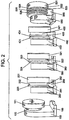
Figure 2 shows perspective views of end caps coupled with sockets -
Figure 3 is a perspective view of an exemplary socket -
Figure 4 is a top view of an exemplary socket -
Figure 5 is a front view of an exemplary socket -
Figure 6 is a side view of an exemplary socket -
Figure 7 is a perspective view of an exemplary end cap -
Figure 8 is a side view of an exemplary end cap -
Figure 9 is a top view of an exemplary end cap -
Figure 10 is a front view of an exemplary end cap -
Figure 11 is an exemplary pespective view of a socket -
Figure 12 is an exemplary top view of a socket -
Figure 13 is an exemplary front view of a socket -
Figure 14 is an exemplary side view of a socket -
Figure 15 is a perspective view of an exemplary end cap -
Figure 16 is a side view of an exemplary end cap -
Figure 17 is a top view of an exemplary end cap -
Figure 18 is a front view of an exemplary end cap -
Figure 19 is a perspective view of an exemplary socket -
Figure 20 is a top view of an exemplary socket -
Figure 21 is a front view of an exemplary socket -
Figure 22 is a side view of an exemplary socket -
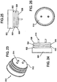
Figure 23 is a perspective view of an exemplary end cap -
Figure 24 is a side view of an exemplary end cap -
Figure 25 is a top view of an exemplary end cap -
Figure 26 is a front view of an exemplary end cap -
Figure 27 is a perspective view of an exemplary socket -
Figure 28 is a top view of an exemplary socket -
Figure 29 is a front view of an exemplary socket -
Figure 30 is a side view of an exemplary socket -
Figure 30 is a side view of an exemplary socket -
Figure 31 is a perspective view of an exemplary end cap -
Figure 32 is a side view of an exemplary end cap -
Figure 33 is a top view of an exemplary end cap -
Figure 34 is a front view of an exemplary end cap -
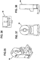
Figure 35 is a perspective view of an exemplary socket -
Figure 36 is a top view of an exemplary socket -
Figure 37 is a front view of an exemplary socket -
Figure 38 is a side view of an exemplary socket -
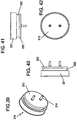
Figure 39 is a perspective view of an exemplary end cap -
Figure 40 is a side view of an exemplary end cap -
Figure 41 is a top view of an exemplary end cap -
Figure 42 is a front view of an exemplary end cap -
Figure 43 is a side view of an exemplary socket -
Figure 44 is a front view of an exemplary socket -
Figure 45 is a perspective view of an exemplary socket and end cap -
Figure 46 is a side view of an exemplary end cap -
Figure 47 is a side view of an exemplary end cap -
Figure 48 is a front view of an exemplary end cap -
Figure 49 is a perspective view of an exemplary end cap -
Figure 50 is a front view of an exemplary end cap coupled with a socket key -
Figure 51 is a perspective view of an exemplary end cap coupled with a socket key -
Figure 52 is a front view of an exemplary end cap coupled with a socket key -
Figure 53 is a perspective view of an exemplary end cap coupled with a socket key -
Figure 54 is a front view of an exemplary end cap coupled with a socket key -
Figure 55 is a perspective view of an exemplary end cap coupled with a socket key -
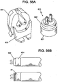
Figure 56 is a composite view of end caps and sockets -
Figure 57 is a side view of an exemplary socket -
Figure 58 is a side view of an exemplary end cap -
Figure 59 is a side view of an exemplary socket -
Figure 60 is a side view of an exemplary end cap -
Figure 61 is a perspective view of end caps and a socket -
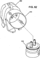
Figure 62 is a perspective view of end caps and a socket -
Figure 63 is a perspective view of conventional end caps. -
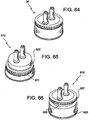
Figure 64 is a perspective view of a conventional end cap. -
Figure 65 is a perspective view of an exemplary end cap -
Figure 66 is a perspective view of an exemplary end cap -
Figures 67 is a perspective view of a conventional end cap. -
Figures 68 is a top view of a conventional end cap. -
Figures 69 is a side view of a conventional end cap. -
Figures 70 is a bottom view of a conventional end cap. -
Figure 71 is a perspective view of an exemplary end cap -
Figure 72 is a top view of an exemplary end cap -
Figure 73 is a side view of an exemplary end cap -
Figure 74 is a bottom view of an exemplary end cap -
Figure 75 is a perspective view of an exemplary end cap -
Figure 76 is a top view of an exemplary end cap -
Figure 77 is a side view of an exemplary end cap -
Figure 78 is a bottom view of an exemplary end cap -
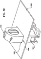
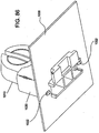
Figures 79-86 illustrate various views of an assembly of an exemplary socket, socket adaptor, and end cap -
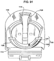
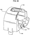
Figures 87-95 illustrate various views of an assembly of an exemplary socket, socket adaptor, and end cap -
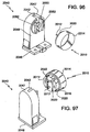
Figure 96 shows a perspective view of an end cap and socket according to at least an embodiment. -
Figure 97 shows a perspective view of an end cap and socket according to at least an embodiment. -
Figure 98 shows a perspective view of an end cap and socket according to at least an embodiment. -
Figure 99 shows a perspective view of an end cap and socket according to at least an embodiment. -
Figure 100 shows an exploded perspective view of a socket according to at least an embodiment. -
Figure 101 shows a perspective view of a socket according to at least an embodiment. -
Figure 102 shows an exploded side view of a socket according to at least an embodiment. -
Figure 103 shows a side view of a socket according to at least an embodiment. -
Figure 104 shows an exploded top view of a socket according to at least an embodiment. -
Figure 105 shows a top view of a socket according to at least an embodiment. -
Figure 106 shows various views of end caps according to various embodiments. -
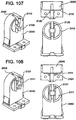
Figure 107 shows various views of a socket according to at least an embodiment. -
Figure 108 shows various views of a socket according to at least an embodiment. -
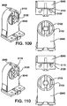
Figure 109 shows various views of a socket according to at least an embodiment. -
Figure 110 shows various views of a socket according to at least an embodiment. -
Figure 111 shows various views of a socket according to at least an embodiment. -
Figure 112 shows various views of a socket according to at least an embodiment. -
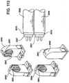
Figure 113 shows lamps with end caps and sockets according to at least an embodiment. -
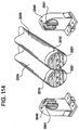
Figure 114 shows lamps with end caps and sockets according to at least an embodiment. -
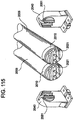
Figure 115 shows lamps with end caps and sockets according to at least an embodiment. -
Figure 116 shows an end cap and socket according to at least an embodiment. -
Figure 117 shows an exploded perspective view of an end cap with adaptor inserts according to at least an embodiment. -
Figure 118 shows a perspective view of an end cap with adaptors according to at least an embodiment. -
Figure 119 shows an exploded perspective view of an end cap with an adaptor according to at least an embodiment. -
Figure 120 shows a perspective view of an end cap with an adaptor according to at least an embodiment. -
Figure 121 shows an exploded perspective view of an exemplary end cap and adaptor -
Figure 122 shows a perspective view of an exemplary end cap and adaptor -
Figures 1-2 illustrate exemplary sockets and end caps. - In particular,
Figures 1-10 illustrateend cap 110 andsocket 150.End cap 110 may include a firstcylindrical portion 121 and a secondcylindrical portion 122. Firstcylindrical portion 121 has a given length and diameter and is open on one end to receive a lamp bulb (not shown) therein. Secondcylindrical portion 122 is positioned adjacent to first cylindrical portion in an axial direction. Secondcylindrical portion 122 also has a diameter that is different than the diameter of firstcylindrical portion 121. WhileFigures 1-2 and7-10 show that the diameter of secondcylindrical portion 122 is smaller than the diameter of firstcylindrical portion 121, it will be readily understood that the diameter of the second cylindrical portion may be larger than that of the first cylindrical portion in other examples, to be used with a socket having an appropriately sized key portion. -
End cap 110 may also include anend face 112 that is positioned at an end of secondcylindrical portion 122 away from firstcylindrical portion 121. Contact pins 114 may extend fromend face 112 of theend cap 110, extending in a direction perpendicular to endface 112. Contact pins 114 may be structured to provide electrical connections to the lamp bulb.Figures 7-10 show contact pins 114 arranged in a medium bi-pin configuration, but it will be understood that other pin spacings can also be easily substituted. - As seen in
Figures 3-6 ,socket 150 has afront face 152, aback face 154, a pin-receivingend 156, and abase end 158.Socket 150 may include aninsertion groove 160 structured to receive the contact pins 114 ofend cap 110.Insertion groove 160 begins at the pin-receivingend 156 and extends in a direction towardbase end 158. -
Socket 150 may also include arotation groove 164 that is generally circular in shape.Rotation groove 164 is cut into the front face of the socket body and intersects withinsertion groove 160.Socket 150 may also include electrical contacts that are positioned withinrotation groove 164. When contact pins 114 ofend cap 110 are rotated inrotation groove 164, contact pins 114 can come in contact with the electrical contacts, thus creating an electrical connection between the lamp bulb and thesocket 150. -
Socket 150 may also include akey portion 170 that projects fromfront face 152. Atop surface 172 ofkey portion 170 is proximate to rotation groove 164 and may be shaped as a circular arc. It is noted that the word "top" is only used as a point of reference, and is not meant to indicate thatsocket 150 must be oriented in a particular way. -
Key portion 170 has a height and depth so that it can be mated withend cap 110. For example, as seen inFigure 2 , secondcylindrical portion 122 ofend cap 110 aligns withkey portion 170. The height ofkey portion 170 is also configured such that when secondcylindrical portion 122 rests onkey portion 170, contacts pins 114 are in position to be rotated throughrotation groove 164. It will be understood that the dimensions ofkey portion 170 and secondcylindrical portion 122 can be varied to create many possible combinations of mated pairs ofsockets 150 andend caps 170. - These features of
key portion 170 help to prevent other end caps from being coupled withsocket 150. For example, if conventional end cap 10 (seen inFigure 63 ) were used withsocket 150, the body ofend cap 10 would abut withkey portion 170, and contact pins ofend cap 10 would not be inserted far enough intoinsertion groove 160 to be rotated throughrotation groove 164. This can also be seen inFigure 56 , which shows aconventional end cap 20 that does not properly couple withsocket 650 because it abuts withkey portion 670. - This ability of
socket 150 to prevent coupling with conventional end caps is an important safety feature. For example, a socket may be connected to a power supply of a certain magnitude. If a user inserts a bulb and end cap into the socket that is not compatible with the power supply, then the bulb and/or socket could be damaged, and there is a risk of electrical shock to the user or a risk of sparking and fire. Thus, asocket 150 withkey portion 170 can be configured to only accept bulbs withend caps 110 having a properly sized secondcylindrical portion 122, thereby helping to ensure that only a properly selected bulb is inserted, and thereby preventing damage to property and ensuring the safety of workers. -
Figures 1-2 and57-58 illustrateend cap 210 andsocket 250 according to another example. -
End cap 210 may include a firstcylindrical portion 221, a secondcylindrical portion 222, and a thirdcylindrical portion 223. Firstcylindrical portion 221 has a given length and diameter and is open on one end to receive a lamp bulb (not shown) therein. Secondcylindrical portion 222 is positioned adjacent to first cylindrical portion in an axial direction. Secondcylindrical portion 222 also has a diameter that is different than the diameter of firstcylindrical portion 221. WhileFigure 58 shows that the diameter of secondcylindrical portion 222 is smaller than the diameter of firstcylindrical portion 221, it will be readily understood that the diameter of the second cylindrical portion may be larger than that of the first cylindrical portion in other examples, to be used with a socket having an appropriately sized key portion. -
End cap 210 may also include thirdcylindrical portion 223. Thirdcylindrical portion 223 is positioned adjacent to secondcylindrical portion 222 in an axial direction, and has a diameter different than the diameter of secondcylindrical portion 222. WhileFigure 58 shows that the diameter of secondcylindrical portion 222 is smaller than the diameter of thirdcylindrical portion 223, it will be readily understood that the diameter of the second cylindrical portion may be larger than that of the third cylindrical portion in other examples to be used with a socket having an appropriately sized key portion. -
End cap 210 may also include anend face 212 that is positioned at an end of thirdcylindrical portion 223 away from firstcylindrical portion 221. Contact pins 214 may extend fromend face 212 of theend cap 210, extending in a direction perpendicular to endface 212. Contact pins 214 may be structured to provide electrical connections to the lamp bulb.Figure 58 show contact pins 214 arranged in a medium bi-pin configuration, but it will be understood that other pin spacings can also be easily substituted. -
Socket 250 is of similar structure tosocket 150 described above, but has a differentkey portion 270.Key portion 270 projects from afront face 252 ofsocket 250.Key portion 270 may include a firstkey segment 271 adjacent tofront face 252 and a secondkey segment 272 positioned adjacent to firstkey segment 271 in a direction away fromfront face 252. In the particular example seen inFigure 57 , firstkey segment 271 is in the form of a groove, and secondkey segment 272 is in the form of a ridge. As seen inFigure 2 , whenend cap 210 couples withsocket 250, thirdcylindrical portion 223 can couple with firstkey segment 271 and secondcylindrical portion 222 can couple with secondkey segment 272.End cap 210 can then be rotated to lock contact pins 214 into place. - It will be understood that
key portion 270 ofsocket 250 can prevent coupling with unmatched end caps. For example, if a conventional end cap were inserted intosocket 250, the end cap would abut withkey portion 270 and it would not be able to rotate the conventional end cap to lock the contact pins into place. As noted in detail above, this ability to prevent coupling with non-mated end caps is an important safety feature. -
Figures 11-18 illustrate anend cap 310 andsocket 350 according to another example.End cap 310 may include a firstcylindrical portion 321 and a secondcylindrical portion 322. Firstcylindrical portion 321 has a given length and diameter and is open on one end to receive a lamp bulb (not shown) therein. Secondcylindrical portion 322 is positioned adjacent to first cylindrical portion in an axial direction. Secondcylindrical portion 322 also has a diameter that is different than the diameter of firstcylindrical portion 321. WhileFigure 15-18 show that the diameter of secondcylindrical portion 322 is smaller than the diameter of firstcylindrical portion 321, it will be readily understood that the diameter of the second cylindrical portion may be larger than that of the first cylindrical portion in other examples, to be used with a socket having an appropriately sized key portion. -
End cap 310 may also include thirdcylindrical portion 323. Thirdcylindrical portion 323 is positioned adjacent to secondcylindrical portion 322 in an axial direction, and has a diameter different than the diameter of secondcylindrical portion 322. WhileFigures 15-18 show that the diameter of secondcylindrical portion 322 is smaller than the diameter of thirdcylindrical portion 323, it will be readily understood that the diameter of the second cylindrical portion may be larger than that of the third cylindrical portion in other examples, to be used with a socket having an appropriately sized key portion. -
End cap 310 may also include fourthcylindrical portion 324. Fourthcylindrical portion 324 is positioned adjacent to thirdcylindrical portion 323 in an axial direction, and has a diameter different than the diameter of thirdcylindrical portion 323. WhileFigures 15-18 show that the diameter of fourthcylindrical portion 324 is smaller than the diameter of thirdcylindrical portion 323, it will be readily understood that the diameter of the fourth cylindrical portion may be larger than that of the third cylindrical portion in other examples, to be used with a socket having an appropriately sized key portion. -
End cap 310 may also include anend face 312 that is positioned at an end of fourthcylindrical portion 324 away from firstcylindrical portion 321. Contact pins 314 may extend fromend face 312 of theend cap 310, extending in a direction perpendicular to endface 312. Contact pins 314 may be structured to provide electrical connections to the lamp bulb.Figures 15-18 show contact pins 314 arranged in a medium bi-pin configuration, but it will be understood that other pin spacings can also be easily substituted. - As seen in
Figures 11-14 ,socket 350 has afront face 352, a back face 354, a pin-receivingend 356, and abase end 358.Socket 350 may include aninsertion groove 360 structured to receive the contact pins 314 ofend cap 310.Insertion groove 360 begins at the pin-receivingend 356 and extends in a direction towardbase end 358. -
Socket 350 may also include a rotation groove that is generally circular in shape. Rotation groove is cut into the front face of the socket body and intersects withinsertion groove 360.Socket 350 may also include electrical contacts that are positioned within the rotation groove. When contact pins 314 ofend cap 310 are rotated in rotation groove, contact pins 314 can come in contact with the electrical contacts, thus creating an electrical connection between the lamp bulb and thesocket 350. -
Socket 350 may also includekey portion 370.Key portion 370 projects from afront face 352 ofsocket 350.Key portion 370 may include a firstkey segment 381 adjacent tofront face 352, a secondkey segment 382 positioned adjacent to firstkey segment 381 in a direction away fromfront face 352, and a thirdkey segment 383 positioned adjacent to secondkey segment 382 in a direction away fromfront face 352. In the particular example seen inFigures 11-14 , firstkey segment 381 is in the form of a ridge, secondkey segment 382 is in the form of a groove, and thirdkey segment 383 is in the form of a ridge. As seen inFigure 2 , whenend cap 310 couples withsocket 350, fourthcylindrical portion 324 can couple with firstkey segment 381, thirdcylindrical portion 323 can couple with secondkey segment 382, and secondcylindrical portion 322 can couple with thirdkey segment 383.End cap 310 can then be rotated to lock contact pins 314 into place. - It will be understood that
key portion 370 ofsocket 350 can prevent coupling with unmatched end caps. For example, if a conventional end cap were inserted intosocket 350, the end cap would abut withkey portion 370 and it would not be able to rotate the conventional end cap to lock the contact pins into place. As noted in detail above, this ability to prevent coupling with non-mated end caps is an important safety feature. -
Figures 1-2 and59-60 illustrateend cap 410 andsocket 450 according to another example. -
End cap 410 may include a firstcylindrical portion 421, a secondcylindrical portion 422, a thirdcylindrical portion 423, a fourthcylindrical portion 424, and a fifthcylindrical portion 425. Firstcylindrical portion 421 has a given length and diameter and is open on one end to receive a lamp bulb (not shown) therein. Secondcylindrical portion 422 is positioned adjacent to first cylindrical portion in an axial direction. Secondcylindrical portion 422 also has a diameter that is different than the diameter of firstcylindrical portion 421. WhileFigure 60 shows that the diameter of secondcylindrical portion 422 is smaller than the diameter of firstcylindrical portion 421, it will be readily understood that the diameter of the second cylindrical portion may be larger than that of the first cylindrical portion in other examples, to be used with a socket having an appropriately sized key portion. -
End cap 410 may also include thirdcylindrical portion 423. Thirdcylindrical portion 423 is positioned adjacent to secondcylindrical portion 422 in an axial direction, and has a diameter different than the diameter of secondcylindrical portion 422. WhileFigure 60 shows that the diameter of secondcylindrical portion 422 is smaller than the diameter of thirdcylindrical portion 423, it will be readily understood that the diameter of the second cylindrical portion may be larger than that of the third cylindrical portion in other examples, to be used with a socket having an appropriately sized key portion. -
End cap 410 may also include fourthcylindrical portion 424. Fourthcylindrical portion 424 is positioned adjacent to thirdcylindrical portion 423 in an axial direction, and has a diameter different than the diameter of thirdcylindrical portion 423. WhileFigure 60 shows that the diameter of fourthcylindrical portion 424 is smaller than the diameter of thirdcylindrical portion 424, it will be readily understood that the diameter of the fourth cylindrical portion may be larger than that of the third cylindrical portion in other examples, to be used with a socket having an appropriately sized key portion. -
End cap 410 may also include fifthcylindrical portion 425. Fifthcylindrical portion 425 is positioned adjacent to fourthcylindrical portion 424 in an axial direction, and has a diameter different than the diameter of fourthcylindrical portion 424. WhileFigure 60 shows that the diameter of fourthcylindrical portion 424 is smaller than the diameter of fifthcylindrical portion 425, it will be readily understood that the diameter of the fourth cylindrical portion may be larger than that of the fifth cylindrical portion in other examples, to be used with a socket having an appropriately sized key portion. -
End cap 410 may also include anend face 412 that is positioned at an end of fifthcylindrical portion 425 away from firstcylindrical portion 421. Contact pins 414 may extend fromend face 412 of theend cap 410, extending in a direction perpendicular to endface 412. Contact pins 414 may be structured to provide electrical connections to the lamp bulb.Figure 60 show contact pins 414 arranged in a medium bi-pin configuration, but it will be understood that other pin spacings can also be easily substituted. -
Socket 450 is of similar structure to other sockets described above, but has a differentkey portion 470.Key portion 470 projects from afront face 452 ofsocket 450.Key portion 470 may include a firstkey segment 481 adjacent tofront face 452, a secondkey segment 482 positioned adjacent to firstkey segment 481 in a direction away fromfront face 452, a thirdkey segment 483 positioned adjacent to firstkey segment 482 in a direction away fromfront face 452, and a fourthkey segment 484 positioned adjacent to firstkey segment 481 in a direction away fromfront face 452. In the particular example seen inFigure 58 , firstkey segment 481 is in the form of a groove, secondkey segment 482 is in the form of a ridge, thirdkey segment 483 is in the form of a groove, and fourthkey segment 483 is in the form of a ridge. As seen inFigure 2 , whenend cap 410 couples withsocket 450, third cylindrical portion fifthcylindrical portion 425 can couple with firstkey segment 481, fourthcylindrical portion 424 can couple with secondkey segment 482, thirdcylindrical portion 423 can couple with thirdkey segment 483, and secondcylindrical portion 422 can couple with fourthkey segment 484.End cap 410 can then be rotated to lock contact pins 414 into place. - It will be understood that
key portion 470 ofsocket 450 can prevent coupling with unmatched end caps. For example, if a conventional end cap were inserted intosocket 450, the end cap would abut withkey portion 470 and it would not be able to rotate the conventional end cap to lock the contact pins into place. As noted in detail above, this ability to prevent coupling with non-mated end caps is an important safety feature. -
Figures 27-34 illustrate anend cap 510 andsocket 550 according to another example.End cap 510 may include a firstcylindrical portion 521 and a secondcylindrical portion 522. Firstcylindrical portion 521 has a given length and diameter and is open on one end to receive a lamp bulb (not shown) therein. Secondcylindrical portion 522 is positioned adjacent to first cylindrical portion in an axial direction. Secondcylindrical portion 522 also has a diameter that is different than the diameter of firstcylindrical portion 521. WhileFigures 31-34 show that the diameter of secondcylindrical portion 522 is smaller than the diameter of firstcylindrical portion 521, it will be readily understood that the diameter of the second cylindrical portion may be larger than that of the first cylindrical portion in other examples, to be used with a socket having an appropriately sized key portion. -
End cap 510 may also include thirdcylindrical portion 523. Thirdcylindrical portion 523 is positioned adjacent to secondcylindrical portion 522 in an axial direction, and has a diameter different than the diameter of secondcylindrical portion 522. WhileFigures 31-34 show that the diameter of secondcylindrical portion 522 is smaller than the diameter of thirdcylindrical portion 523, it will be readily understood that the diameter of the second cylindrical portion may be larger than that of the third cylindrical portion in other examples, to be used with a socket having an appropriately sized key portion. -
End cap 510 may also include fourthcylindrical portion 524. Fourthcylindrical portion 524 is positioned adjacent to thirdcylindrical portion 523 in an axial direction, and has a diameter different than the diameter of thirdcylindrical portion 523. WhileFigures 31-34 show that the diameter of fourthcylindrical portion 524 is smaller than the diameter of thirdcylindrical portion 524, it will be readily understood that the diameter of the fourth cylindrical portion may be larger than that of the third cylindrical portion in other examples, to be used with a socket having an appropriately sized key portion. -
End cap 510 may also include fifthcylindrical portion 525. Fifthcylindrical portion 525 is positioned adjacent to fourthcylindrical portion 524 in an axial direction, and has a diameter different than the diameter of fourthcylindrical portion 524. WhileFigures 31-34 show that the diameter of fourthcylindrical portion 524 is smaller than the diameter of fifthcylindrical portion 525, it will be readily understood that the diameter of the fourth cylindrical portion may be larger than that of the fifth cylindrical portion in other examples, to be used with a socket having an appropriately sized key portion. -
End cap 510 may also include sixthcylindrical portion 526. Sixthcylindrical portion 526 is positioned adjacent to fifthcylindrical portion 525 in an axial direction, and has a diameter different than the diameter of fifthcylindrical portion 525. WhileFigures 31-34 show that the diameter of sixthcylindrical portion 526 is smaller than the diameter of fifthcylindrical portion 525, it will be readily understood that the diameter of the sixth cylindrical portion may be larger than that of the fifth cylindrical portion in other examples, to be used with a socket having an appropriately sized key portion. -
End cap 510 may also include anend face 512 that is positioned at an end of sixthcylindrical portion 526 away from firstcylindrical portion 521. Contact pins 514 may extend fromend face 512 of theend cap 510, extending in a direction perpendicular to endface 512. Contact pins 514 may be structured to provide electrical connections to the lamp bulb.Figures 31-34 show contact pins 514 arranged in a medium bi-pin configuration, but it will be understood that other pin spacings can also be easily substituted. - As seen in
Figures 27-30 ,socket 550 has afront face 552, aback face 554, a pin-receivingend 556, and abase end 558.Socket 550 may include aninsertion groove 560 structured to receive the contact pins 514 ofend cap 510.Insertion groove 560 begins at the pin-receivingend 556 and extends in a direction towardbase end 558. -
Socket 550 may also include a rotation groove that is generally circular in shape. Rotation groove is cut into the front face of the socket body and intersects withinsertion groove 560.Socket 550 may also include electrical contacts that are positioned within the rotation groove. When contact pins 514 ofend cap 510 are rotated in rotation groove, contact pins 514 can come in contact with the electrical contacts, thus creating an electrical connection between the lamp bulb and thesocket 550. -
Socket 550 may also includekey portion 570.Key portion 570 projects from afront face 552 ofsocket 550.Key portion 570 may include a firstkey segment 581 adjacent tofront face 552, a secondkey segment 582 positioned adjacent to firstkey segment 581 in a direction away fromfront face 552, a thirdkey segment 583 positioned adjacent to secondkey segment 582 in a direction away fromfront face 552, a fourthkey segment 584 positioned adjacent to thirdkey segment 583 in a direction away fromfront face 552, and a fifthkey segment 585 positioned adjacent to fourthkey segment 584 in a direction away fromfront face 552. In the particular example seen inFigures 11-14 , firstkey segment 581 is in the form of a ridge, secondkey segment 582 is in the form of a groove, thirdkey segment 583 is in the form of a ridge, fourthkey segment 584 is in the form of a groove, and fifthkey segment 585 is in the form of a ridge. - As seen in
Figure 2 , whenend cap 510 couples withsocket 550, sixthcylindrical portion 526 can couple with firstkey segment 581, fifthcylindrical portion 525 can couple with secondkey segment 582, fourthcylindrical portion 524 can couple with thirdkey segment 583, thirdcylindrical portion 523 can couple with fourthkey segment 584, and secondcylindrical portion 522 can couple with fifthkey segment 585.End cap 510 can then be rotated to lock contact pins 514 into place. - It will be understood that
key portion 570 ofsocket 550 can prevent coupling with unmatched end caps. For example, if a conventional end cap were inserted intosocket 550, the end cap would abut withkey portion 570 and it would not be able to rotate the conventional end cap to lock the contact pins into place. As noted in detail above, this ability to prevent coupling with non-mated end caps is an important safety feature. - The examples described above have included key portions with a particular arrangement of grooves and ridges. However, it will be understood that the particular sequence of grooves and ridges can be modified so that many different specific configurations of key portions can be possible. For example,
Figures 19-22 and35-38 show at least some possible examples of other possible key configurations onsocket 50. - Additionally, the Figures described above show an end cap of size T12. However, it will be understood that other embodiments are possible with different sized end caps. For example,
Figures 56 shows an example with aT5 end cap 610 having a firstcylindrical portion 621 and a secondcylindrical portion 622.Figure 56 further shows asocket 650 havingkey portion 670 for use withend cap 610.Figures 61-62 show at least some additional possible examples includingend caps socket 650. -
Figures 43-49 show anend cap 710 andsocket 750 according to at least another example.Socket 750 is similar to the sockets discussed above in that akey portion 770 projects from afront face 752 ofsocket 750. However, as seen inFigures 44-45 ,key portion 770 has akey protrusion 780 projecting in a direction towardscentral hole 755. -
End cap 710 may be a cylindrical body that is open on one end to receive a bulb therein. Anend face 712 may be found on a second end ofend cap 710, and contact pins 714 may extend perpendicularly fromend face 712. - Additionally,
end cap 710 may include akey groove 720.Key groove 720 is formed in the end face ofend cap 710, and extends along the outer circumference ofend face 712. In the example shown inFigures 43-49 ,key groove 720 extends for at least 90 degrees of the circumference ofend face 712, allowing for theend cap 710 to be rotated at least 90 degrees to lock contact pins 714 into place. The size ofkey groove 720 in a radial direction (i.e., a radial direction of end face 712) corresponds to a height ofkey protrusion 780. -
Key protrusion 780 andkey groove 720 are important features that help to insure proper coupling ofend cap 710 withsocket 750. For example, whenend cap 710 is properly inserted intosocket 750,key groove 720 aligns withkey protrusion 780, andsocket 710 can be rotated, as seen inFigures 50-51 . However, ifsocket 710 is not properly inserted, then the cylindrical body ofend cap 710 will abut withkey protrusion 780 and contact pins 714 will not be properly aligned insocket 750, thus preventingend cap 710 from being rotated. - This is an important safety feature in that it helps to insure that a proper end cap and bulb is inserted into a particular socket. Additionally, this feature is important for applications in which it is necessary to insure that the contact pins of an end cap are connected to electrical contacts of a particular polarity. For example it may be necessary to insure that one of the contact pins is always connected to a positive voltage, and the other contact pin is connected to ground. In this situation, such an alignment can be insured because an
end cap 710 withkey groove 720 can only be inserted and rotated in asocket 750 withkey protrusion 780 in one particular orientation. If a user tries to rotateend cap 710 in a direction opposite of the desired direction, one end ofkey groove 720 will abut withkey protrusion 780, thus preventing rotation. Additionally, ifend cap 710 was inserted opposite of the property orientation, the cylindrical body ofend cap 710 would abut withkey protrusion 780, thus preventingcontact pins 714 from being fully inserted and rotated. -
Figures 43-51 show an example in whichkey protrusion 780 is located at approximately the center ofkey portion 770. However, it will be understood that other orientations are possible. For example,Figures 52-53 show an example wherekey protrusion 880 is positioned partway between the center ofkey portion 870 and an end ofkey portion 880. Accordingly,key groove 820 ofend cap 810 is located at an appropriate circumferential position to fit thekey protrusion 880. - Similarly,
Figures 54-55 show an example in whichkey protrusion 980 is located at an end ofkey portion 970. Accordingly,key groove 920 ofend cap 910 is located at an appropriate circumferential position to fitkey portion 980. As shown inFigures 50-55 , many different configurations are possible to allow for many different mated pairs of sockets and end caps. - The examples shown in
Figures 43-55 show key protrusions formed against a front face of a socket and end caps having a key groove cut into the end face. However, it will be understood that other configurations are possible. For example, if the key portion is extended further away from the face of the socket, the key protrusion can be formed such that a space exists between the key portion and the front face of the socket. In this situation, the corresponding key groove on the end cap would not be cut into the end face, but instead could be formed at a position on the outer circumference of the cylindrical body of the end cap. - Additionally, it is possible to form a socket having a key protrusion adjacent to the front face of the socket as well as a second key protrusion displaced in a direction away from the front face of the socket. The corresponding end cap would thus have two key grooves, one cut into the end face and a second cut into the cylindrical body at a position axially displaced from the end face.
-
Figures 65-66 show further examples of end caps of size T5. A conventionalT5 end cap 20 is shown inFigure 64 for comparison.End cap 610 shownFigure 65 is a T5 version of theT12 end cap 110 shown inFigures 7-10 . For example,end cap 610 is provided with a firstcylindrical portion 621 and a secondcylindrical portion 622. Firstcylindrical portion 621 has a given length and diameter and is open on one end to receive a lamp bulb (not shown) therein. Secondcylindrical portion 622 is positioned adjacent to first. cylindrical portion in an axial direction and has a diameter that is different than the diameter of firstcylindrical portion 621. - Similarly,
end cap 615 shown inFigure 66 is a T5 version of theT12 end cap 210 shown inFigures 39-42 . For example,end cap 615 is provided with a firstcylindrical portion 625, a secondcylindrical portion 626, and a thirdcylindrical portion 627. Firstcylindrical portion 625 has a given length and diameter and is open on one end to receive a lamp bulb (not shown) therein. Secondcylindrical portion 626 is positioned adjacent to first cylindrical portion in an axial direction and has a diameter that is different than the diameter of first cylindrical portion 625.Thirdcylindrical portion 627 is positioned adjacent to secondcylindrical portion 626 in an axial direction, and has a diameter different than the diameter of secondcylindrical portion 626. Thirdcylindrical portion 627 may have the same diameter as firstcylindrical portion 625, as seen inFigure 66 , the diameters of firstcylindrical portion 625 and thirdcylindrical portion 627 may be different in other examples. - Figures'71-74 show additional views of
end cap 610 andFigures 75-78 show additional views ofend cap 615. Views ofconventional end cap 20 are shown inFigures 67-70 for comparison. -
Figures 79-86 illustrate an assembly concept for a socket, a socket adaptor, and an end cap. In certain applications, as seen inFigure 79 , asocket 1010 is inserted through acutout 1002 in aplate 1000. When fully inserted,clips 1012 snap into place to keepsocket 1010 in position onplate 1000. - In applications such as seen in
Figures 70-86 , it would not be possible to use a socket such assocket 150 inFigure 3 becausecutout 1002 is not large enough to accommodate an integratedkey portion 170 ofsocket 150. Thus, in order to achieve the benefits of the keying system described above, anadaptor 1020 can be fitted tosocket 1010 oncesocket 1010 is positioned, as seen inFigures 80-82 . To attachadaptor 1020, holes 1004 can be drilled intoplate 1000 nearcutout 1002, and clips 1022 provided onadaptor 1020 can snap intoholes 1004, as seen inFigures 80 and85-86 . - As seen in
Figures 80-82 ,adaptor 1020 comprises a tubular body, and one side of the adaptor, akey portion 1026 is provided. In the example shown inFigures 80-82 ,key portion 1026 is shaped as an arc of a circle.Figure 83 shows acorresponding end cap 1030 that includes a firstcylindrical portion 1031 and a secondcylindrical portion 1032. As seen inFigures 83-84 ,key portion 1026 is structured to receive secondcylindrical portion 1032. - Additionally, as seen in
Figure 81 ,adaptor 1024 can be provided withsocket removal grooves 1024. These grooves provide access toclips 1012 ofsocket 1010 so that a tool can be used to removesocket 1010 fromplate 1000, for example to perform maintenance or replace a socket. -
Figures 87-95 illustrate another possible example of a socket adaptor. For example,Figure 87 shows anadaptor 1120 that is fitted over aconventional socket 1110.Adaptor 1120 comprises a body that is open at one end to fit oversocket 1110. Opposite the open end,adaptor 1120 is provided with anadaptor pin groove 1128 that fits over and corresponds tosocket pin groove 1118. Thus, pins of a lamp base can be inserted throughadaptor pin groove 1128 intosocket pin groove 1118. Additionally, a cutout is provided in afront face 1126 ofadaptor 1120, the cutout being sufficiently large to accommodate an end cap of a lamp. - Additionally a
key portion 1123 may be provided on thefront face 1126 ofadaptor 1120. In the examples shown inFigures 87-94 ,key portion 1123 includes a firstkey segment 1121 and a secondkey segment 1122. Firstkey segment 1121 is adjacent tofront face 1126 and secondkey segment 1122 is positioned adjacent to firstkey segment 1121 in a direction away fromfront face 1126. - In the particular example seen in
Figures 87-94 , firstkey segment 1121 is in the form of a groove, and secondkey segment 1126 is in the form of a ridge. As seen inFigure 87 , whenend cap 1130 couples withsocket 1110 andadaptor 1120, thirdcylindrical portion 1133 can couple with firstkey segment 1121 and secondcylindrical portion 1132 can couple with secondkey segment 1122. In the particular example shown inFigure 87 , firstcylindrical portion 1131 ofend cap 1130 rests outside ofkey portion 1123. - Thus, as illustrated in
Figures 79-94 , conventional sockets can be retrofitted with adaptors to benefit from the safety advantages provided by the keying system. WhileFigures 79-94 show particular examples of adaptors and end caps, it will be understood that adaptors shown inFigures 79-94 can be modified to incorporate any variety of key portions or key segment arrangements, such as those previously discussed or any other possible arrangements. For example, a socket adaptor may be provided with any ofkey portions -
Figures 96 and 97 illustrate embodiments of an end cap and socket system. In particular,Figures 96 and 97 illustrateend cap 2010 andsocket 2040 according to at least one embodiment. -
End cap 2010 may be generally cylindrical in shape and open on one end to receive a lamp bulb therein. For example,end cap 2010 may includecylindrical portion 2014. At a first end ofcylindrical portion 2014, anend face 2016 may be formed. At a second end ofcylindrical portion 2014opposition end face 2016,cylindrical portion 2014 is open and structured to receive a lamp bulb therein. -
End cap 2010 may also include contact pins 2012. Contact pins 2012 extend fromkey disk 2020 in a direction approximately perpendicular to the surface ofkey disk 2020 andend face 2014. Contact pins 2012 are structured such that electrical connection can be provided fromcontact pins 2012 through the key disk and end face to a lamp bulb inserted into the open end ofend cap 2010. - As further seen in
Figures 96-97 ,end cap 2010 may also includekey disk 2020.Key disk 2020 is provided onend face 2016, and is generally cylindrical in shape.Key disk 2020 has a predetermined depth, and includes at least onekey groove 2022 cut into thekey disk 2020 for at least a part of the depth. In the embodiments shown inFigures 96 and 97 , thekey groove 2022 extends completely through the circle defined by thekey disk 2020; i.e., thekey groove 2022 follows the path of a chord of the circle defined bykey disk 2020. However, it will be understood that this is not a requirement, as there may be embodiments in which the key groove does not extend completely throughkey disk 2020. - Additionally, in the embodiment shown in
Figures 96 and 97 , there are twokey grooves 2022 cut intokey disk 2020, andkey grooves 2022 are symmetrically disposed onkey disk 2020. However, it is not necessary thatkey grooves 2022 be symmetrically placed, as some embodiments may include asymmetric key grooves.Figures 96 and 97 also show thatkey grooves 2022 may be parallel. - An embodiment of
socket 2040 is also seen inFigures 96 and 97 .Socket 2040 may include afront face 2046, a pin-receivingend 2047, and abase end 2048.Socket 2040 may also include aninsertion groove 2042 beginning at the pin-receivingend 2047 and extending in a direction toward thebase end 2048.Insertion groove 2042 may be structured such that contact pins 2012 can be inserted therein by sliding the pins intoinsertion groove 2012 in a direction towardsbase end 2048. - As seen in
Figure 100 ,socket 2040 may also include arotation groove 2044 that is generally circular in shape.Rotation groove 2044 is cut into thefront face 2046 ofsocket 2040 and intersects withinsertion groove 2042.Socket 2040 may also include electrical contacts that are positioned withinrotation groove 2044. When contact pins 2012 ofend cap 2010 are rotated inrotation groove 2044, contact pins 2012 can come in contact with the electrical contacts, thus creating an electrical connection between the lamp bulb and thesocket 2040. -
Figures 100-105 show an embodiment of akey piece 2050 that can be inserted intosocket 2040. In general,key piece 2050 is inserted intorotation groove 2044 ofsocket 2040 and is rotatable withinrotation groove 2044.Key piece 2050 may be held in place withinsocket 2040 through the use of clips provided onsocket 2040 and/orkey piece 2050, or by any other suitable means for maintainingkey piece 2050 in a rotatable state withinsocket 2040. - As seen in
Figures 100-105 ,key piece 2050 may include akey piece body 2056, akey piece face 2058, and at least onekey rib 2052. One embodiment ofkey piece body 2056 may be a hollow cylinder having a first and second end, the cylinder being structured to fit within the rotation groove.Key piece body 2056 may also include a key piecebody insertion groove 2057 that extends from the first end of thekey piece body 2056 and extending in a direction toward the second end of thekey piece body 2056. Whenkey piece 2050 is assembled withsocket 2040, key piecebody insertion groove 2057 is perpendicular tofront face 2046 ofsocket 2040, key piecebody insertion groove 2057 can align withinsertion groove 2042 whenkey piece 2050 is oriented accordingly. -
Figures 100-105 further illustrate thatkey piece 2058 may be attached to the first end ofkey piece body 2056.Key piece face 2058 may be approximately parallel tofront face 2046 ofsocket 2040, andkey piece face 2058 may include a key piece faceinsertion groove 2059 aligned with key piecebody insertion groove 2057. Key piece faceinsertion groove 2059 extends in a straight line through the center ofkey piece face 2058. - Additionally, at least one
key rib 2052 may be provided onkey piece face 2058.Key rib 2052 extends from the key piece face in a direction away fromfront face 2046 ofsocket 2040. As further seen inFigures 100 and104 ,key rib 2052 may be parallel to key piece faceinsertion groove 2059. - In general, the
key ribs 2052 provided onkey piece 2050 will be configured so as to correspond to thekey grooves 2022 on a mated end cap. For example, as seen in the embodiments shown inFigures 96-97 , thekey ribs 2052 extend completely through the circle defined by thekey piece face 2058; i.e.,key ribs 2052 follow the path of a chord of the circle defined bykey piece face 2058, similar tokey grooves 2022 onend cap 2010 inFigures 96-97 . However, it will be understood that this is not a requirement, as there may be embodiments in which the key rib does not extend completely acrosskey piece face 2058. - Additionally, in the embodiment shown in
Figures 96-97 , there are twokey ribs 2052 provided onkey piece face 2058, and key ribs are symmetrically disposed onkey piece face 2058, similar tokey grooves 2022 seen inFigures 96-97 . However, it is not necessary that key ribs be symmetrically placed, as some embodiments may include asymmetric key ribs.Figures 96-97 also show thatkey ribs 2052 may be parallel. - To operate the end cap and socket system shown in
Figures 96-97 ,end cap 2010 is positioned such that the contact pins can be slid intoinsertion groove 2042. If thekey disk 2020 ofend cap 2010 is properly mated withkey piece 2050 ofsocket 2040, thenkey ribs 2052 will insert intokey grooves 2022 as theend cap 2010 is slid into position. If an end cap and socket are not properly mated, thenkey ribs 2052 will not align withkey grooves 2022, and it will not be possible to couple the end cap with socket. - Once
end cap 2010 is fully inserted into thesocket 2040,end cap 2010 can be rotated relative tosocket 2040. Although hidden from view bykey piece face 2058, contact pins 2012 will rotate throughrotation groove 2044 asend cap 2010 is rotated. Contact pins will come into contact with the electrical contacts within the rotation groove, and be locked into place through elastic force of the electrical contacts or any other suitable means for maintaining contact betweenelectrical pins 2012 and the electrical contacts in the rotation groove. - The ability to prevent improper mating between sockets and end caps is an important safety feature. For example, a socket may be connected to a power supply of a certain magnitude. If a user inserts a bulb and end cap into the socket that is not compatible with the power supply, then the bulb and/or socket could be damaged, and there is a risk of electrical shock to the user or a risk of sparking and fire. Thus, a
socket 2040 withkey piece 2050 can be configured to only accept bulbs withend caps 2010 having a properly configurekey disk 2020, thereby helping to ensure that only a properly selected bulb is inserted, and thereby preventing damage to property and ensuring the safety of workers. -
Figures 98-99 show at least another embodiment of an end cap and socket system. For example, theend cap 2010 inFigures 98-99 is provided with akey disk 2021 that includes fourkey grooves 2022. Accordingly,socket 2040 inFigures 98-99 is provided with akey piece 2051 that includes fourkey ribs 2022. The fourkey ribs 2052 ofkey piece 2051 are configured to correspond to the fourkey grooves 2022 ofkey disk 2021. -
Figure 106 shows views of various embodiments of key disks. For example, in comparingkey disks key disk 2100 has a short distance between the key grooves, while key 2106 has a larger distance between the key grooves. -
Figures 107-112 show views ofsockets 2040 with various embodiments of key disks. For example, the sockets inFigures 107-112 are provided withkey disks key ribs Figures 107-112 that the distance between the key ribs can be varied to accommodate various different end cap key disk designs. -
Figures 113-116 show various views of other embodiments of end caps and sockets. For example,Figures 113-115 show sockets 2040 withkey pieces 2051 having four key ribs andend caps 2010 withkey disks 2021 having four key grooves. End caps 2010 are shown positioned on an end oflamp bulb 2005. Figure 2021 shows an embodiment of akey piece 2050 with two sockets and anend cap 2010 with akey disk 2020 having twokey grooves 2022. -
Figures 117-120 also show that conventional end caps having longer pins can be fitted with adaptors to be used with a socket having a key piece. For example, as seen inFigures 117-118 , an adaptor can have abody portion 2200 with ahole 2202 extending throughbody portion 2200.Body portion 2200 can be fitted overcontact pins 2012 such that contact pins 2012 are inserted intohole 2202. In the embodiment shown inFigures 117-118 ,body portions 2200 may be small cylinders that fit over each individual contact pin. -
Figures 119-120 show one possible example embodiment of an adaptor. For example, inFigures 119-120 , the adaptor can have abody portion 2210 with twoholes 2212 extending throughbody portion 2210. To attachbody portion 2212 to an end cap, contact pins 2012 are inserted throughholes 2212. Theadaptors -
Figures 121-122 illustrate at least another example of and end cap with an adaptor. For example,Figure 121 shows an exploded view of aconventional end cap 2010 withpins 2012 and anadaptor body portion 2300. It will be appreciated thatpins 2012 can be elongated pins in some embodiments.Adaptor body portion 2300 hasholes 2312 that are structured to fit over pins 2012. In other words, pins 2012 are inserted throughholes 2312.Adaptor body portion 2300 is also provided withkey grooves 2322. As seen inFigure 122 ,adaptor body portion 2300 can be fitted overpins 2010 and fastened to endcap 2010. - It is noted that in the example shown in
Figures 121-122 ,adaptor body portion 2300 corresponds tokey disk 2020 shown inFigure 97 . However, it will be appreciated that many key disks can be used as the basis foradaptor body portion 2300, for examplekey disk 2021 shown inFigure 98 , any of disks 2100- 2106, or any other appropriate key disk. - In addition to retrofitting old end caps, the adaptor embodiment shown in
Figures 121-122 can be used in manufacturing new end caps as well. For example, existing manufacturing facilities can be used to manufactureend caps 2010 and then anadaptor body portion 2300 can be fastened tokey disk 2010. This can provide significant time and cost advantages over retooling a manufacturing facility to produce end caps with integrated key disks. - The adaptors are an important feature because existing lamp bases can be upgraded through the use of an adaptor to ensure that the lamp base only couples in a particular way with appropriate sockets. This allows a user to achieve the operation and safety advantages described above without have to discard previously purchased lamps. Additionally, if an end cap with longer pins and no adaptor is used in a socket with a key piece, portions of the contact pins will be exposed outside the surface of the socket. This will create a risk of fire or shock that can cause property damage or injury to an operator.
- Additionally, the Figures described above show an end cap of size T12. However, it will be understood that other embodiments are possible with different sized end caps and sockets.
- While the description above refers to particular examples and embodiments of the present invention, it will be understood that many modifications may be made.
- The accompanying claims are intended to define the scope of the present invention.
- The presently disclosed embodiments are therefore to be considered in all respects as illustrative and not restrictive, the scope of the invention being indicated by the appended claims, rather than the foregoing description.
Claims (16)
- An end cap and socket system for use with a lamp bulb, the system comprising:an end cap (2010) comprising:a cylindrical portion (2014);an end face (2016) formed at a first end of the cylindrical portion (2014);a key disk (2020) provided on the end face (2016) and having a key groove (2022) cut into the key disk (2020); anda plurality of contact pins (2012) extending from the key disk (2020);wherein the plurality of contact pins (2012) is structured to provide electrical connection to the lamp bulb; anda socket (2040) having a front face (2046), a pin-receiving end (2047), and a base end (2048), the socket (2040) comprising:an insertion groove (2042) structured to receive the contact pins (2012) therein, wherein the insertion groove (2042) begins at the pin-receiving end (2047) and extends in a direction toward the base end (2048);a rotation groove (2044) cut into the front face (2046) of the socket (2040),wherein the rotation groove (2044) intersects with the insertion groove (2042); and a plurality of electrical contacts positioned within the rotation groove (2044);characterized in thatthe socket (2040) further comprises a key piece (2050) inserted into the rotation groove (2044) and being rotatable within the rotation groove (2044), the key piece (2050) being provided with a key rib (2052) andin that the key groove (2022) and the key rib (2052) are configured such that when the end cap (2010) is inserted into the socket (2040), the key groove (2022) and the key rib (2052) are aligned so that the key rib (2052) can slide into the key groove (2022).
- The end cap and socket system of claim 1, wherein the key piece (2050) comprises:a key piece body (2056) comprising a hollow cylinder having a first and second end and structured to fit within the rotation groove (2044), the key piece body (2056) having a key piece body insertion groove (2057) extending from the first end of the key piece body (2056) and extending in a direction toward the second end of the key piece body (2056);a key piece face (2058) attached to the first end of the key piece body (2056), the key piece face (2058) being approximately parallel to the front face (2046) of the socket (2040) and having a key piece face insertion groove (2059) aligned with the key piece body insertion groove (2057) and extending in a straight line through a center of the key piece face (2058);wherein the key rib (2052) extends from the key piece face (2058) in a direction away from the front face (2046) of the socket (2040); andthe key rib(2052) is parallel to the key piece face insertion groove (2059).
- The end cap and socket system according to one of claims 1 and 2, wherein the key disk (2020) comprises two key grooves (2022) cut into the key disk (2020);
and the key piece (2050) comprises two key ribs (2052);
wherein the key grooves (2022) and the key ribs (2052) are configured such that when the end cap (2010) is inserted into the socket (2040), the key grooves and the key ribs (2052) are aligned so that the key ribs (2052) can slide into the key grooves (2022). - The end cap and socket system according to one of claims 1 and 2, wherein the key disk (2020) comprises four key grooves (2022) cut into the key disk (2020);
and the key piece (2050) comprises four key ribs (2052);
wherein the key grooves (2022) and the key ribs (2052) are configured such that when the end cap (2010) is inserted into the socket (2040), the key grooves and the key ribs (2052) are aligned so that the key ribs (2052) can slide into the key grooves (2022). - An end cap (2030) for use with a lamp bulb, the end cap comprising:a cylindrical portion (2014);an end face (2016) formed at a first end of the cylindrical portion (2014);a key disk (2020) provided on the end face (2016) and having a key groove (2022) cut into the key disk (2020); anda plurality of contact pins (2012) extending from the key disk (2020);wherein the plurality of contact pins (2012) is structured to provide electrical connection to the lamp bulb; andcharacterized in that the key groove (2011) is formed as a chord of a circle defined by the key disk (2020).
- The end cap (2030) according to claim 5, wherein the key disk (2020) comprises two key grooves (2022) cut into the key disk (2020), the two key grooves (2022) are configured such that when the end cap (2010) is inserted into a socket (2040) comprising two key ribs (2052) the key grooves (2022) are aligned so that the key ribs (2052) can slide into the key grooves (2022).
- The end cap (2030) according to claim 5, wherein the key disk (2020) comprises four key grooves (2022) cut into the key disk (2020), the four key grooves (2022) are configured such that when the end cap (2010) is inserted into a socket (2040) comprising four key ribs (2052) the key grooves (2022) are aligned so that the key ribs (2052) can slide into the key grooves (2022).
- An end cap adaptor (2300) for use with an end cap (2010) comprising a cylindrical portion, an end face formed at a first end of the cylindrical portion, and a plurality of contact pins (2012) extending from the end face, the end cap adaptor (2300)
comprising:a body portion shaped as a disk;a plurality of holes (2312) extending through the body portion;a key groove (2322) being cut into a face of the body portion; andwherein the plurality of holes (2312) are arranged such that the plurality of contact pins (2012) can be inserted through the plurality of holes (2312),characterized in that the key groove (2011) is formed as a chord of a circle defined by the body portion. - The end cap adaptor (2300) according to claim 8, wherein the body portion comprises two key grooves (2322) cut into the body portion, and the key grooves (2322) are configured such that when the end cap adaptor (2300) is inserted into the socket (2040) comprising two key rips (2052) provided on the key piece (2050);
the key grooves (2322) and the key ribs (2052) are aligned so that the key ribs (2052) can slide into the key grooves (2322). - The end cap adaptor (2300) according to claim 8, wherein the body portion comprises four key grooves (2322) cut into the body portion, and the key grooves (2322) are configured such that when the end cap adaptor (2300) is inserted into the socket (2040) comprising four key rips (2052) provided on the key piece (2050);
the key grooves (2322) and the key ribs (2052) are aligned so that the key ribs (2052) can slide into the key grooves (2322). - A socket (2040) for use with a lamp bulb, the socket (2040) being structured to couple with an end cap (2010) according to claim 5, and
wherein the socket (2040) comprising:a socket body having a front face (2046), a pin-receiving end (2047), and a base end (2048), the socket (2040) further comprising:an insertion groove (2042) structured to receive the contact pins (2012) therein, wherein the insertion groove (2042) begins at the pin-receiving end (2047) and extends in a direction toward the base end (2048);a rotation groove (2044) cut into the front face (2046) of the socket (2040), wherein the rotation groove (2044) intersects with the insertion groove (2042);anda plurality of electrical contacts positioned within the rotation groove (2044);characterized in thatthe socket (2040) further comprises a key piece (2050) inserted into the rotation groove (2044) and being rotatable within the rotation groove (2044), the key piece (2050) being provided with a key rib (2052) andin that the key groove (2022) and the key rib (2052) are configured such that when the end cap (2010) is inserted into the socket (2040), the key groove (2022) and the key rib (2052) are aligned so that the key rib (2052) can slide into the key groove (2022). - The socket of claim 11, wherein the key piece (2050) comprises:a key piece body (2056) comprising a hollow cylinder having a first and second end and structured to fit within the rotation groove (2044), the key piece body (2056) having a key piece body insertion groove (2057) extending from the first end of the key piece body (2056) and extending in a direction toward the second end of the key piece body (2056);a key piece face (2058) attached to the first end of the key piece body (2056), the key piece face (2058) being approximately parallel to the front face (2046) of the socket (2040) and having a key piece face insertion groove (2059) aligned with the key piece body insertion groove (2057) and extending in a straight line through a center of the key piece face (2058);wherein the key rib (2052) extends from the key piece face (2058) in a direction away from the front face (2046) of the socket (2040); andthe key rib(2052) is parallel to the key piece face insertion groove (2059).
- The socket (2040) according to one of claims 11 and 12, wherein the key piece (2050) comprises two key ribs (2052); and the key ribs (2052) are configured such that when the socket (2040) is coupled with an end cap (2010) comprising two key grooves (2022) cut into the key disk (2020)
the key grooves (2022) and the key ribs (2052) are aligned so that the key ribs (2052) can slide into the key grooves (2022). - The socket (2040) according to one of claims 11 and 12, wherein the key piece (2050) comprises four key ribs (2052); and the key ribs (2052) are configured such that when the socket (2040) is coupled with an end cap (2010) comprising four key grooves (2022) cut into the key disk (2020)
the key grooves (2022) and the key ribs (2052) are aligned so that the key ribs (2052) can slide into the key grooves (2022) - A key piece (2050) structured to be inserted into a rotation groove (2044) of a socket (2040) and being rotatable within the rotation groove (2044), wherein the socket (2040) having a front face (2046), a pin-receiving end (2047), and a base end (2048), the socket (2040) further comprising:an insertion groove (2042) structured to receive the contact pins (2012) therein, wherein the insertion groove (2042) begins at the pin-receiving end (2047) and extends in a direction toward the base end (2048);the rotation groove (2044) cut into the front face (2046) of the socket (2040), wherein the rotation groove (2044) intersects with the insertion groove (2042); anda plurality of electrical contacts positioned within the rotation groove (2044);characterized in that said key piece (2050) further being structured to couple with an end cap according to claim 5 and comprising:a key piece body (2056) comprising a hollow cylinder having a first and second end and structured to fit within the rotation groove (2044), the key piece body (2056) having a key piece body insertion groove (2057) extending from the first end of the key piece body (2056) and extending in a direction toward the second end of the key piece body (2056);a key piece face (2058) attached to the first end of the key piece body (2056), the key piece face (2058) being approximately parallel to the front face (2046) of the socket (2040) and having a key piece face insertion groove (2059) aligned with the key piece body insertion groove (2057) and extending in a straight line through a center of the key piece face (2058); anda key rib (2052) extending from the key piece face (2058) in a direction away from the front face (2046) of the socket (2040); andin that the key rib(2052) is parallel to the key piece face insertion groove (2059);and in that the key groove (2022) and the key rib (2052) are configured such that when the end cap (2010) is inserted into the socket (2040), the key groove (2022) and the key rib (2052) are aligned so that the key rib (2052) can slide into the key groove (2022).
- The key piece (2050) according to claim 15, wherein the key piece (2050) comprises a plurality of key ribs (2052) extending from the key piece face (2058) in a direction away from the front face (2046) of the socket (2040) and each of the plurality of the key ribs (2052) is parallel to the key piece face insertion groove (2059).
Applications Claiming Priority (3)
| Application Number | Priority Date | Filing Date | Title |
|---|---|---|---|
| US6098308P | 2008-06-12 | 2008-06-12 | |
| US11633608P | 2008-11-20 | 2008-11-20 | |
| PCT/US2009/047200 WO2010005682A2 (en) | 2008-06-12 | 2009-06-12 | End cap, socket, and adaptors for use with a lamp |
Publications (3)
| Publication Number | Publication Date |
|---|---|
| EP2286490A2 EP2286490A2 (en) | 2011-02-23 |
| EP2286490A4 EP2286490A4 (en) | 2013-03-13 |
| EP2286490B1 true EP2286490B1 (en) | 2016-04-20 |
Family
ID=41507650
Family Applications (1)
| Application Number | Title | Priority Date | Filing Date |
|---|---|---|---|
| EP09794887.1A Active EP2286490B1 (en) | 2008-06-12 | 2009-06-12 | End cap, socket, and adaptors for use with a lamp |
Country Status (4)
| Country | Link |
|---|---|
| US (1) | US8308497B2 (en) |
| EP (1) | EP2286490B1 (en) |
| CA (1) | CA2716945C (en) |
| WO (1) | WO2010005682A2 (en) |
Families Citing this family (20)
| Publication number | Priority date | Publication date | Assignee | Title |
|---|---|---|---|---|
| CA2716945C (en) * | 2008-06-12 | 2016-11-15 | Light Sources, Inc. | End cap, socket, and adaptors for use with a lamp |
| USD634274S1 (en) * | 2009-04-21 | 2011-03-15 | A.A.G. Stucchi S.R.L. | Lamp socket |
| CN102062368B (en) * | 2010-09-28 | 2013-07-31 | 上海亚明灯泡厂有限公司 | Replacement support lamp tube and lamp head cover |
| CN102086986B (en) * | 2011-02-28 | 2013-01-09 | 鸿富锦精密工业(深圳)有限公司 | LED (light-emitting diode) lighting tube |
| USD697253S1 (en) * | 2011-05-13 | 2014-01-07 | Panasonic Corporation | Light-emitting diode lamp |
| USD702870S1 (en) * | 2011-05-13 | 2014-04-15 | Panasonic Corporation | Light-emitting diode lamp |
| DE202012100937U1 (en) * | 2012-03-15 | 2012-04-03 | Dirk Steinmann | light assembly |
| TW201414950A (en) * | 2012-10-05 | 2014-04-16 | Lextar Electronics Corp | End cap of lamp |
| USD727849S1 (en) * | 2013-02-08 | 2015-04-28 | Panasonic Intellectual Property Management Co., Ltd. | Socket for light-emitting diode lamp |
| US20160178169A1 (en) * | 2013-03-11 | 2016-06-23 | Koninklijke Philips N.V. | Adapter device for retrofitting in lighting arrangements |
| US9062870B2 (en) | 2013-05-10 | 2015-06-23 | Caldesso, Llc | UV bulb configuration |
| WO2015031785A1 (en) | 2013-08-30 | 2015-03-05 | American Air & Water, Inc. | Ultraviolet disinfection lighting system |
| KR101945787B1 (en) | 2013-09-06 | 2019-02-12 | 몰렉스 엘엘씨 | Lamp socket |
| USD787737S1 (en) * | 2015-05-22 | 2017-05-23 | Viroj Khanampornpan | Lamp holder |
| USD787111S1 (en) * | 2015-05-22 | 2017-05-16 | Viroj Khanampornpan | Lamp holder |
| IT201900017039A1 (en) * | 2019-09-23 | 2021-03-23 | Gs Plastics S A S Di Giovanni Gervasio & C | LED LAMP |
| US12485199B2 (en) | 2021-01-03 | 2025-12-02 | Richard Nelson Wills, JR. | Fluid purification systems and methods |
| USD1091478S1 (en) * | 2023-12-08 | 2025-09-02 | Phillip C. House | Lamp plug |
| CN118208697A (en) * | 2024-01-10 | 2024-06-18 | 厦门普为光电科技有限公司 | Bracket, lamp tube, lighting device with foolproof structure, and installation and modification method thereof |
| US12234970B1 (en) * | 2024-06-06 | 2025-02-25 | Aleddra Inc. | Lampholder system with lock |
Citations (1)
| Publication number | Priority date | Publication date | Assignee | Title |
|---|---|---|---|---|
| US5634820A (en) * | 1994-03-11 | 1997-06-03 | Lights Of America, Inc. | Fluorescent light adaptor module |
Family Cites Families (60)
| Publication number | Priority date | Publication date | Assignee | Title |
|---|---|---|---|---|
| US1157026A (en) | 1911-10-20 | 1915-10-19 | William F Meschenmoser | Plug-switch. |
| US1937537A (en) * | 1931-10-28 | 1933-12-05 | Du Pont Cellophane Co Inc | Tube |
| GB461912A (en) | 1935-09-27 | 1937-02-26 | Gen Electric Co Ltd | Improvements in and relating to electric lamp sockets |
| US2137174A (en) * | 1938-03-25 | 1938-11-15 | Gen Electric | Tubular lamp base and socket |
| US2288376A (en) | 1939-11-22 | 1942-06-30 | Gen Electric | Lamp holder |
| GB536273A (en) | 1939-12-08 | 1941-05-08 | British Thomson Houston Co Ltd | Improvements relating to electric lamp sockets |
| US2248987A (en) * | 1940-02-29 | 1941-07-15 | Rca Corp | Electrode assembly |
| US2259378A (en) | 1940-09-05 | 1941-10-14 | Herman H Heidkamper | Lamp socket |
| US2324683A (en) | 1940-11-20 | 1943-07-20 | Pass & Seymour Inc | Socket for fluorescent lamps |
| US2295757A (en) | 1941-03-01 | 1942-09-15 | Pass & Seymour Inc | Fluorescent lamp socket |
| US2262091A (en) | 1941-03-27 | 1941-11-11 | Gen Electric | Socket for tubular lamps |
| US2284367A (en) | 1941-04-09 | 1942-05-26 | Gen Electric | Combined lamp socket and switch |
| US2356601A (en) * | 1942-07-07 | 1944-08-22 | Gen Electric | Adapter for discharge lamps |
| US2473925A (en) | 1945-03-15 | 1949-06-21 | Bryant Electric Co | Lamp holder for double-ended discharge lamps |
| US2505112A (en) * | 1945-07-20 | 1950-04-25 | Electric Service Mfg Company | Fluorescent light fixture |
| US2596056A (en) | 1946-04-08 | 1952-05-06 | Tinnerman Products Inc | Lamp socket mounting and fastener therefor |
| NL68261C (en) * | 1946-08-20 | |||
| US2659058A (en) * | 1951-02-09 | 1953-11-10 | Western Electric Co | Fluorescent light socket |
| US3297977A (en) | 1964-04-17 | 1967-01-10 | Leviton Manufacturing Co | Electrical fixture for panel mounting |
| US3446954A (en) * | 1967-03-13 | 1969-05-27 | Lake Shore Markers Inc | Electrical conversion plug |
| US3716816A (en) * | 1970-12-28 | 1973-02-13 | W Johnson | Coupling for securing a lamp in a lampholder |
| US3975073A (en) | 1971-12-02 | 1976-08-17 | Westinghouse Electric Corporation | Fluorescent lampholder with means for circuit interruption |
| US4084873A (en) | 1976-09-14 | 1978-04-18 | Grate Anton J | Lamp and holder combination with adapter |
| US4275325A (en) * | 1979-08-13 | 1981-06-23 | Guim R | Fluorescent lamp with plural sealed enclosures and electrical connector therefor |
| US4633132A (en) * | 1984-11-19 | 1986-12-30 | North American Philips Consumer Electronics Corp. | Self-adhering cathode ray tube base |
| DE3708762A1 (en) * | 1987-03-18 | 1988-09-29 | Philips Patentverwaltung | LAMP FOR A ROD-SHAPED FLUORESCENT LAMP |
| US4854888A (en) | 1988-05-31 | 1989-08-08 | Gte Products Corporation | Lamp base |
| US4878854A (en) | 1988-05-31 | 1989-11-07 | Gte Products Corporation | Lamp base |
| SE462938B (en) * | 1988-12-16 | 1990-09-17 | Combinova Ab | ADAPTER INTENDED TO REPLACE A CONVENTIONAL LAMP MACHINE IN A LAMP LIGHT |
| DE9206294U1 (en) * | 1992-05-11 | 1992-07-02 | Patent-Treuhand-Gesellschaft für elektrische Glühlampen mbH, 8000 München | Adapter for a single-ended low-pressure discharge lamp |
| US5489813A (en) * | 1993-12-27 | 1996-02-06 | Jung; Huang H. | Neon lamp |
| US5422487A (en) | 1994-07-27 | 1995-06-06 | Light Sources, Inc. | Waste water purification system with complementary interlocking germicidal lamp and socket construction |
| DE19530115C1 (en) | 1995-08-16 | 1997-01-30 | Broekelmann Jaeger & Busse | Lamp holder for fluorescent lamps |
| JPH09148014A (en) * | 1995-11-29 | 1997-06-06 | Tec Corp | Socket for fluorescent lamp |
| US5904415A (en) * | 1996-06-25 | 1999-05-18 | H. E. Williams, Inc. | Fluorescent bulb connector assembly |
| US6632100B1 (en) * | 1997-04-23 | 2003-10-14 | Anthony, Inc. | Lighting system method and apparatus socket assembly lamp insulator assembly and components thereof |
| US6290522B1 (en) | 1998-02-19 | 2001-09-18 | Leviton Manufacturing Co., Inc. | Fluorescent lampholder |
| US6558020B1 (en) | 1999-01-31 | 2003-05-06 | Walter Holzer | Flat reflector lamp for fluorescent tubes |
| US6582253B1 (en) * | 2000-06-01 | 2003-06-24 | Kenneth Lau | Lock-in compact fluorescent lamp (CFL) adaptor |
| USD487252S1 (en) | 2002-01-22 | 2004-03-02 | Uv Doctor Llc | Ceramic ultraviolet lamp holder |
| EP1348902A1 (en) | 2002-03-26 | 2003-10-01 | Koninklijke Philips Electronics N.V. | Lamp and lamp holder with peripheral locking means |
| JP3963120B2 (en) | 2002-05-14 | 2007-08-22 | 住友電装株式会社 | Switch connector device |
| US6893144B2 (en) | 2003-01-30 | 2005-05-17 | Ben Fan | Waterproof assembly for ornamental light string |
| USD521451S1 (en) * | 2003-05-15 | 2006-05-23 | Koninklijke Philips Electronics, N.V. | End cap for fluorescent lamp |
| US6884103B1 (en) * | 2004-02-04 | 2005-04-26 | Light Sources, Inc. | Secure lamp base and socket |
| CN100592462C (en) * | 2004-03-04 | 2010-02-24 | 皇家飞利浦电子股份有限公司 | Fluorescent lamp and method for manufacturing fluorescent lamp |
| DE102004011635A1 (en) * | 2004-03-10 | 2005-10-06 | Bjb Gmbh & Co.Kg | Socket for double ended tubular fluorescent lamps with two-pin sockets |
| US7125159B2 (en) * | 2004-04-20 | 2006-10-24 | Sea Gull Lighting Products, Inc. | Non-defeatable fluorescent adapter for incandescent fixture |
| USD537414S1 (en) * | 2004-10-29 | 2007-02-27 | Totsuken Co., Ltd. | Base of discharge lamp |
| US7052171B1 (en) * | 2004-12-15 | 2006-05-30 | Emteq, Inc. | Lighting assembly with swivel end connectors |
| US7097327B1 (en) | 2005-03-21 | 2006-08-29 | Daniel W Barton | Lever pivot safety stop socket for fluorescent lamps |
| JP2006310145A (en) | 2005-04-28 | 2006-11-09 | Toshiba Lighting & Technology Corp | Lamp socket and luminaire |
| JP2006331701A (en) * | 2005-05-24 | 2006-12-07 | Matsushita Electric Works Ltd | Lamp socket |
| US7390225B2 (en) | 2005-06-24 | 2008-06-24 | Trojan Technologies | Radiation lamp and radiation source module incorporating same |
| JP4621092B2 (en) | 2005-08-12 | 2011-01-26 | 日本圧着端子製造株式会社 | Fluorescent tube mounting structure |
| US8021189B2 (en) * | 2006-02-27 | 2011-09-20 | Light Sources Inc. | Ultraviolet lamp for use in water purifiers |
| US7604505B2 (en) * | 2006-02-27 | 2009-10-20 | Light Sources, Inc. | Ultraviolet lamp for use in water purifiers |
| US8040032B2 (en) * | 2006-09-25 | 2011-10-18 | Lightsources Inc. | Smooth action, spring loaded, twist locking, radial lugged safety connector for lamp |
| CN100552284C (en) * | 2006-10-17 | 2009-10-21 | 马士科技有限公司 | Pluggable fluorescent lamps and their sockets |
| CA2716945C (en) * | 2008-06-12 | 2016-11-15 | Light Sources, Inc. | End cap, socket, and adaptors for use with a lamp |
-
2009
- 2009-06-12 CA CA2716945A patent/CA2716945C/en active Active
- 2009-06-12 WO PCT/US2009/047200 patent/WO2010005682A2/en not_active Ceased
- 2009-06-12 EP EP09794887.1A patent/EP2286490B1/en active Active
- 2009-06-12 US US12/483,834 patent/US8308497B2/en active Active
Patent Citations (1)
| Publication number | Priority date | Publication date | Assignee | Title |
|---|---|---|---|---|
| US5634820A (en) * | 1994-03-11 | 1997-06-03 | Lights Of America, Inc. | Fluorescent light adaptor module |
Also Published As
| Publication number | Publication date |
|---|---|
| EP2286490A4 (en) | 2013-03-13 |
| US8308497B2 (en) | 2012-11-13 |
| WO2010005682A3 (en) | 2010-04-15 |
| EP2286490A2 (en) | 2011-02-23 |
| CA2716945A1 (en) | 2010-01-14 |
| WO2010005682A2 (en) | 2010-01-14 |
| CA2716945C (en) | 2016-11-15 |
| US20100015843A1 (en) | 2010-01-21 |
Similar Documents
| Publication | Publication Date | Title |
|---|---|---|
| CA2716945C (en) | End cap, socket, and adaptors for use with a lamp | |
| US6884103B1 (en) | Secure lamp base and socket | |
| US5637010A (en) | Connector pair | |
| US7604505B2 (en) | Ultraviolet lamp for use in water purifiers | |
| US7661977B2 (en) | Snap-lock connector | |
| GB2469855A (en) | Locking apparatus for electrical connectors | |
| US20210210892A1 (en) | Rotatable Electric Plug | |
| US6422051B1 (en) | Combination cable lock | |
| CN201853866U (en) | Plug-in structure of illuminating lamp | |
| US12537341B2 (en) | Locking electrical contact device with switch | |
| US20100120278A1 (en) | Multi-angular power adapter | |
| CN101595607B (en) | Lampholders and lighting equipment with such lampholders | |
| EP2118967B1 (en) | Ultraviolet lamp for use in water purifiers | |
| CN220440018U (en) | Quick power plug connector | |
| EP2392054B1 (en) | Snap-lock connector | |
| US7066758B2 (en) | Electrical socket | |
| EP2139073B1 (en) | Electrical connection bridge and block | |
| CN110690612B (en) | Misplug-proof electric connector assembly | |
| BRPI0613114A2 (en) | sliding pin plug and locking device | |
| CN210182721U (en) | Two-core elbow connector | |
| CN221305159U (en) | Connector with insert and close discernment and mistake proofing insert function | |
| US20060133082A1 (en) | Locking socket for biax plug-in lamp | |
| CN214254898U (en) | Circular three-piece radio frequency integrated connector | |
| CN210068659U (en) | Interlocking connector and interlocking assembly | |
| CN117559177A (en) | A connector with mating recognition and mismating prevention functions |
Legal Events
| Date | Code | Title | Description |
|---|---|---|---|
| PUAI | Public reference made under article 153(3) epc to a published international application that has entered the european phase |
Free format text: ORIGINAL CODE: 0009012 |
|
| 17P | Request for examination filed |
Effective date: 20100901 |
|
| AK | Designated contracting states |
Kind code of ref document: A2 Designated state(s): AT BE BG CH CY CZ DE DK EE ES FI FR GB GR HR HU IE IS IT LI LT LU LV MC MK MT NL NO PL PT RO SE SI SK TR |
|
| AX | Request for extension of the european patent |
Extension state: AL BA RS |
|
| DAX | Request for extension of the european patent (deleted) | ||
| A4 | Supplementary search report drawn up and despatched |
Effective date: 20130213 |
|
| RIC1 | Information provided on ipc code assigned before grant |
Ipc: H01R 33/08 20060101AFI20130207BHEP Ipc: H01R 33/94 20060101ALI20130207BHEP |
|
| 17Q | First examination report despatched |
Effective date: 20140520 |
|
| GRAP | Despatch of communication of intention to grant a patent |
Free format text: ORIGINAL CODE: EPIDOSNIGR1 |
|
| RIC1 | Information provided on ipc code assigned before grant |
Ipc: H01R 13/64 20060101ALN20150901BHEP Ipc: H01R 33/94 20060101ALI20150901BHEP Ipc: H01R 33/08 20060101AFI20150901BHEP |
|
| INTG | Intention to grant announced |
Effective date: 20150923 |
|
| GRAS | Grant fee paid |
Free format text: ORIGINAL CODE: EPIDOSNIGR3 |
|
| REG | Reference to a national code |
Ref country code: DE Ref legal event code: R079 Ref document number: 602009038038 Country of ref document: DE Free format text: PREVIOUS MAIN CLASS: H01R0013620000 Ipc: H01R0033080000 |
|
| RIC1 | Information provided on ipc code assigned before grant |
Ipc: H01R 33/94 20060101ALI20160126BHEP Ipc: H01R 13/64 20060101ALN20160126BHEP Ipc: H01R 33/08 20060101AFI20160126BHEP |
|
| RIC1 | Information provided on ipc code assigned before grant |
Ipc: H01R 33/08 20060101AFI20160209BHEP Ipc: H01R 13/64 20060101ALN20160209BHEP Ipc: H01R 33/94 20060101ALI20160209BHEP |
|
| GRAA | (expected) grant |
Free format text: ORIGINAL CODE: 0009210 |
|
| INTG | Intention to grant announced |
Effective date: 20160303 |
|
| AK | Designated contracting states |
Kind code of ref document: B1 Designated state(s): AT BE BG CH CY CZ DE DK EE ES FI FR GB GR HR HU IE IS IT LI LT LU LV MC MK MT NL NO PL PT RO SE SI SK TR |
|
| REG | Reference to a national code |
Ref country code: GB Ref legal event code: FG4D |
|
| REG | Reference to a national code |
Ref country code: CH Ref legal event code: EP |
|
| REG | Reference to a national code |
Ref country code: AT Ref legal event code: REF Ref document number: 793348 Country of ref document: AT Kind code of ref document: T Effective date: 20160515 |
|
| REG | Reference to a national code |
Ref country code: IE Ref legal event code: FG4D |
|
| REG | Reference to a national code |
Ref country code: DE Ref legal event code: R096 Ref document number: 602009038038 Country of ref document: DE |
|
| REG | Reference to a national code |
Ref country code: LT Ref legal event code: MG4D |
|
| REG | Reference to a national code |
Ref country code: AT Ref legal event code: MK05 Ref document number: 793348 Country of ref document: AT Kind code of ref document: T Effective date: 20160420 |
|
| REG | Reference to a national code |
Ref country code: NL Ref legal event code: MP Effective date: 20160420 |
|
| PG25 | Lapsed in a contracting state [announced via postgrant information from national office to epo] |
Ref country code: FI Free format text: LAPSE BECAUSE OF FAILURE TO SUBMIT A TRANSLATION OF THE DESCRIPTION OR TO PAY THE FEE WITHIN THE PRESCRIBED TIME-LIMIT Effective date: 20160420 Ref country code: NL Free format text: LAPSE BECAUSE OF FAILURE TO SUBMIT A TRANSLATION OF THE DESCRIPTION OR TO PAY THE FEE WITHIN THE PRESCRIBED TIME-LIMIT Effective date: 20160420 Ref country code: NO Free format text: LAPSE BECAUSE OF FAILURE TO SUBMIT A TRANSLATION OF THE DESCRIPTION OR TO PAY THE FEE WITHIN THE PRESCRIBED TIME-LIMIT Effective date: 20160720 Ref country code: PL Free format text: LAPSE BECAUSE OF FAILURE TO SUBMIT A TRANSLATION OF THE DESCRIPTION OR TO PAY THE FEE WITHIN THE PRESCRIBED TIME-LIMIT Effective date: 20160420 Ref country code: LT Free format text: LAPSE BECAUSE OF FAILURE TO SUBMIT A TRANSLATION OF THE DESCRIPTION OR TO PAY THE FEE WITHIN THE PRESCRIBED TIME-LIMIT Effective date: 20160420 |
|
| PG25 | Lapsed in a contracting state [announced via postgrant information from national office to epo] |
Ref country code: HR Free format text: LAPSE BECAUSE OF FAILURE TO SUBMIT A TRANSLATION OF THE DESCRIPTION OR TO PAY THE FEE WITHIN THE PRESCRIBED TIME-LIMIT Effective date: 20160420 Ref country code: LV Free format text: LAPSE BECAUSE OF FAILURE TO SUBMIT A TRANSLATION OF THE DESCRIPTION OR TO PAY THE FEE WITHIN THE PRESCRIBED TIME-LIMIT Effective date: 20160420 Ref country code: GR Free format text: LAPSE BECAUSE OF FAILURE TO SUBMIT A TRANSLATION OF THE DESCRIPTION OR TO PAY THE FEE WITHIN THE PRESCRIBED TIME-LIMIT Effective date: 20160721 Ref country code: PT Free format text: LAPSE BECAUSE OF FAILURE TO SUBMIT A TRANSLATION OF THE DESCRIPTION OR TO PAY THE FEE WITHIN THE PRESCRIBED TIME-LIMIT Effective date: 20160822 Ref country code: ES Free format text: LAPSE BECAUSE OF FAILURE TO SUBMIT A TRANSLATION OF THE DESCRIPTION OR TO PAY THE FEE WITHIN THE PRESCRIBED TIME-LIMIT Effective date: 20160420 Ref country code: AT Free format text: LAPSE BECAUSE OF FAILURE TO SUBMIT A TRANSLATION OF THE DESCRIPTION OR TO PAY THE FEE WITHIN THE PRESCRIBED TIME-LIMIT Effective date: 20160420 Ref country code: SE Free format text: LAPSE BECAUSE OF FAILURE TO SUBMIT A TRANSLATION OF THE DESCRIPTION OR TO PAY THE FEE WITHIN THE PRESCRIBED TIME-LIMIT Effective date: 20160420 |
|
| PG25 | Lapsed in a contracting state [announced via postgrant information from national office to epo] |
Ref country code: IT Free format text: LAPSE BECAUSE OF FAILURE TO SUBMIT A TRANSLATION OF THE DESCRIPTION OR TO PAY THE FEE WITHIN THE PRESCRIBED TIME-LIMIT Effective date: 20160420 Ref country code: BE Free format text: LAPSE BECAUSE OF FAILURE TO SUBMIT A TRANSLATION OF THE DESCRIPTION OR TO PAY THE FEE WITHIN THE PRESCRIBED TIME-LIMIT Effective date: 20160420 |
|
| REG | Reference to a national code |
Ref country code: DE Ref legal event code: R097 Ref document number: 602009038038 Country of ref document: DE |
|
| PG25 | Lapsed in a contracting state [announced via postgrant information from national office to epo] |
Ref country code: RO Free format text: LAPSE BECAUSE OF FAILURE TO SUBMIT A TRANSLATION OF THE DESCRIPTION OR TO PAY THE FEE WITHIN THE PRESCRIBED TIME-LIMIT Effective date: 20160420 Ref country code: DK Free format text: LAPSE BECAUSE OF FAILURE TO SUBMIT A TRANSLATION OF THE DESCRIPTION OR TO PAY THE FEE WITHIN THE PRESCRIBED TIME-LIMIT Effective date: 20160420 Ref country code: CZ Free format text: LAPSE BECAUSE OF FAILURE TO SUBMIT A TRANSLATION OF THE DESCRIPTION OR TO PAY THE FEE WITHIN THE PRESCRIBED TIME-LIMIT Effective date: 20160420 Ref country code: EE Free format text: LAPSE BECAUSE OF FAILURE TO SUBMIT A TRANSLATION OF THE DESCRIPTION OR TO PAY THE FEE WITHIN THE PRESCRIBED TIME-LIMIT Effective date: 20160420 Ref country code: SK Free format text: LAPSE BECAUSE OF FAILURE TO SUBMIT A TRANSLATION OF THE DESCRIPTION OR TO PAY THE FEE WITHIN THE PRESCRIBED TIME-LIMIT Effective date: 20160420 Ref country code: MC Free format text: LAPSE BECAUSE OF FAILURE TO SUBMIT A TRANSLATION OF THE DESCRIPTION OR TO PAY THE FEE WITHIN THE PRESCRIBED TIME-LIMIT Effective date: 20160420 |
|
| REG | Reference to a national code |
Ref country code: CH Ref legal event code: PL |
|
| PLBE | No opposition filed within time limit |
Free format text: ORIGINAL CODE: 0009261 |
|
| STAA | Information on the status of an ep patent application or granted ep patent |
Free format text: STATUS: NO OPPOSITION FILED WITHIN TIME LIMIT |
|
| GBPC | Gb: european patent ceased through non-payment of renewal fee |
Effective date: 20160720 |
|
| REG | Reference to a national code |
Ref country code: IE Ref legal event code: MM4A |
|
| 26N | No opposition filed |
Effective date: 20170123 |
|
| REG | Reference to a national code |
Ref country code: FR Ref legal event code: ST Effective date: 20170228 |
|
| PG25 | Lapsed in a contracting state [announced via postgrant information from national office to epo] |
Ref country code: CH Free format text: LAPSE BECAUSE OF NON-PAYMENT OF DUE FEES Effective date: 20160630 Ref country code: FR Free format text: LAPSE BECAUSE OF NON-PAYMENT OF DUE FEES Effective date: 20160630 Ref country code: LI Free format text: LAPSE BECAUSE OF NON-PAYMENT OF DUE FEES Effective date: 20160630 |
|
| PG25 | Lapsed in a contracting state [announced via postgrant information from national office to epo] |
Ref country code: SI Free format text: LAPSE BECAUSE OF FAILURE TO SUBMIT A TRANSLATION OF THE DESCRIPTION OR TO PAY THE FEE WITHIN THE PRESCRIBED TIME-LIMIT Effective date: 20160420 Ref country code: GB Free format text: LAPSE BECAUSE OF NON-PAYMENT OF DUE FEES Effective date: 20160720 Ref country code: IE Free format text: LAPSE BECAUSE OF NON-PAYMENT OF DUE FEES Effective date: 20160612 |
|
| PG25 | Lapsed in a contracting state [announced via postgrant information from national office to epo] |
Ref country code: HU Free format text: LAPSE BECAUSE OF FAILURE TO SUBMIT A TRANSLATION OF THE DESCRIPTION OR TO PAY THE FEE WITHIN THE PRESCRIBED TIME-LIMIT; INVALID AB INITIO Effective date: 20090612 Ref country code: CY Free format text: LAPSE BECAUSE OF FAILURE TO SUBMIT A TRANSLATION OF THE DESCRIPTION OR TO PAY THE FEE WITHIN THE PRESCRIBED TIME-LIMIT Effective date: 20160420 |
|
| PG25 | Lapsed in a contracting state [announced via postgrant information from national office to epo] |
Ref country code: MT Free format text: LAPSE BECAUSE OF NON-PAYMENT OF DUE FEES Effective date: 20160630 Ref country code: TR Free format text: LAPSE BECAUSE OF FAILURE TO SUBMIT A TRANSLATION OF THE DESCRIPTION OR TO PAY THE FEE WITHIN THE PRESCRIBED TIME-LIMIT Effective date: 20160420 Ref country code: MK Free format text: LAPSE BECAUSE OF FAILURE TO SUBMIT A TRANSLATION OF THE DESCRIPTION OR TO PAY THE FEE WITHIN THE PRESCRIBED TIME-LIMIT Effective date: 20160420 Ref country code: LU Free format text: LAPSE BECAUSE OF NON-PAYMENT OF DUE FEES Effective date: 20160612 Ref country code: IS Free format text: LAPSE BECAUSE OF FAILURE TO SUBMIT A TRANSLATION OF THE DESCRIPTION OR TO PAY THE FEE WITHIN THE PRESCRIBED TIME-LIMIT Effective date: 20160420 |
|
| PG25 | Lapsed in a contracting state [announced via postgrant information from national office to epo] |
Ref country code: BG Free format text: LAPSE BECAUSE OF FAILURE TO SUBMIT A TRANSLATION OF THE DESCRIPTION OR TO PAY THE FEE WITHIN THE PRESCRIBED TIME-LIMIT Effective date: 20160420 |
|
| PGFP | Annual fee paid to national office [announced via postgrant information from national office to epo] |
Ref country code: DE Payment date: 20250416 Year of fee payment: 17 |