EP2285509B1 - System for bending a metallic strip - Google Patents
System for bending a metallic strip Download PDFInfo
- Publication number
- EP2285509B1 EP2285509B1 EP08789962.1A EP08789962A EP2285509B1 EP 2285509 B1 EP2285509 B1 EP 2285509B1 EP 08789962 A EP08789962 A EP 08789962A EP 2285509 B1 EP2285509 B1 EP 2285509B1
- Authority
- EP
- European Patent Office
- Prior art keywords
- bending
- strip
- tools
- tool
- hubs
- Prior art date
- Legal status (The legal status is an assumption and is not a legal conclusion. Google has not performed a legal analysis and makes no representation as to the accuracy of the status listed.)
- Active
Links
- 238000005452 bending Methods 0.000 title claims description 92
- 230000000903 blocking effect Effects 0.000 claims description 13
- 238000000034 method Methods 0.000 claims description 8
- 238000004519 manufacturing process Methods 0.000 claims description 5
- 238000010008 shearing Methods 0.000 claims description 3
- 230000005540 biological transmission Effects 0.000 description 4
- 230000000717 retained effect Effects 0.000 description 4
- 230000001360 synchronised effect Effects 0.000 description 3
- 230000001419 dependent effect Effects 0.000 description 1
- 230000000694 effects Effects 0.000 description 1
- 238000003780 insertion Methods 0.000 description 1
- 230000037431 insertion Effects 0.000 description 1
- 230000000007 visual effect Effects 0.000 description 1
Images


Classifications
-
- B—PERFORMING OPERATIONS; TRANSPORTING
- B21—MECHANICAL METAL-WORKING WITHOUT ESSENTIALLY REMOVING MATERIAL; PUNCHING METAL
- B21D—WORKING OR PROCESSING OF SHEET METAL OR METAL TUBES, RODS OR PROFILES WITHOUT ESSENTIALLY REMOVING MATERIAL; PUNCHING METAL
- B21D37/00—Tools as parts of machines covered by this subclass
- B21D37/20—Making tools by operations not covered by a single other subclass
- B21D37/205—Making cutting tools
-
- B—PERFORMING OPERATIONS; TRANSPORTING
- B21—MECHANICAL METAL-WORKING WITHOUT ESSENTIALLY REMOVING MATERIAL; PUNCHING METAL
- B21D—WORKING OR PROCESSING OF SHEET METAL OR METAL TUBES, RODS OR PROFILES WITHOUT ESSENTIALLY REMOVING MATERIAL; PUNCHING METAL
- B21D5/00—Bending sheet metal along straight lines, e.g. to form simple curves
- B21D5/04—Bending sheet metal along straight lines, e.g. to form simple curves on brakes making use of clamping means on one side of the work
- B21D5/042—With a rotational movement of the bending blade
-
- B—PERFORMING OPERATIONS; TRANSPORTING
- B21—MECHANICAL METAL-WORKING WITHOUT ESSENTIALLY REMOVING MATERIAL; PUNCHING METAL
- B21D—WORKING OR PROCESSING OF SHEET METAL OR METAL TUBES, RODS OR PROFILES WITHOUT ESSENTIALLY REMOVING MATERIAL; PUNCHING METAL
- B21D7/00—Bending rods, profiles, or tubes
- B21D7/02—Bending rods, profiles, or tubes over a stationary forming member; by use of a swinging forming member or abutment
- B21D7/022—Bending rods, profiles, or tubes over a stationary forming member; by use of a swinging forming member or abutment over a stationary forming member only
Definitions
- the present invention concerns a system for bending a metallic strip and, in particular, a device and a process for the production of for die-cutting blades starting from a continuous metallic strip which is shaped via successive bending steps and undergoes a final shearing step.
- the devices known in the art for bending metallic strips in particular those intended for the production of die-cutting blades, generally include a system for feeding the continuous metallic strip through a guide aperture, in the vicinity of which one or more bending tools are located. In the majority of cases two bending tools are provided, one to bend the strip to the right (or upwards, for example) and the other to bend the strip to the left (or downwards, for example).
- the strip is fed forward through the guide aperture and temporarily stopped to perform the bending operation.
- the bending tool to be used is positioned near the guide aperture and then rotated to deform the strip as required to the right (or left) at a pre-set angle.
- a bending system with two tools is described, for example, in the United States patent no. US-5870919 , in which the bending tools are retractable tools engaged in appropriate seats of coaxial supporting elements and rotated around their common axis.
- the bending tools can be used in a mutually exclusive way, i.e. keeping one tool in the work position (extended) while the other is kept in the rest position (retracted) and vice versa.
- each tool is supported by a pair of coaxial supporting elements which can rotate around their common axis.
- the supporting elements of a pair are arranged alternately with those of the other pair and, consequently, at least two of them must have a seat for engagement of the bending tool supported, and a groove to permit the movement of the other one.
- the feed section of the strip also has to be changed whenever starting a new production phase with a metallic strip with dimensions or shape different from that of the strip processed previously.
- the object of the present invention is to propose a device and a process for bending metallic strips which overcome the drawbacks of the known technique.
- a particular object of the present invention is to propose a device of the type described above which is mechanically simple to produce.
- a further object of the present invention is to propose a device of the type described above which makes the operations for replacing the bending tools and/or the strip feed section quick and easy.
- the device for bending a metallic strip includes at least one feed section to pass the strip through a guide aperture, at least one pair of bending tools which can rotate around at least one common rotation axis, and means for rotating the bending tools around the common rotation axis.
- the device advantageously includes controllable blocking means to lock the bending tools in positions mutually alongside the guide aperture when they are in the rest condition and to release at least one of the bending tools in the operating condition in which the bending is performed.
- the blocking means can be set to release both the worn tools.
- the new tools can thus be easily positioned and, by setting the blocking means to the locking position, they are ready to proceed with the strip bending operations.
- the blocking means for locking and releasing the bending tools preferably include brackets that can be rotated around an axis perpendicular to the feed direction of the strip.
- the blocking means can be operated in various ways, for example by using pneumatic or electric actuators or similar.
- the bending tools are rotated by means which include controllable engagement members to engage or disengage the opposite ends of the bending tools.
- the means for rotating the bending tools include in particular at least two hubs opposed with respect to the guide aperture; said hubs can rotate around an axis perpendicular to the feed direction of the strip.
- the engagement members are housed in the hubs and are movable in translation along a direction parallel to the rotation axis of the hubs by means of pneumatic or electric actuators or similar.
- the engagement members move between a retracted position inside the hubs, and therefore disengaged from the bending tools, and a position in which they are extracted from the hubs, i.e. engaged with the ends of the bending tools.
- each tool In the bending systems of the known art, in particular in the systems with retractable tools, each tool must necessarily have a slim section throughout its insertion length, as it must fit between the strip being bent and the end of the feed section. The same applies to the known systems with tools engaged in grooves of the rotating supports, which must have a reduced section at the ends in order not to weaken the rotating supports with excessively wide grooves.
- the strip is moved forward through the feed section until a pre-set length emerges from the guide aperture.
- the bending tool to be used After stopping the strip, the bending tool to be used is engaged at its ends by the engagement members which are appropriately extracted from the opposed hubs. In this way, the bending tool to be used rotates integrally with the opposed hubs in order to be rotated around the rotation axis common to both the tools.
- the blocking means combined with the bending tool to be used are then operated to release it from its locking position, while the other tool is kept locked in the rest condition.
- the bending tool to be used is then rotated by a rotation angle sufficient to bend the strip as required, and then re-set to the position corresponding to the rest condition. At this point, if the next bend is required in the same direction, the strip is moved forward again by a pre-set length and, once stopped, bending is performed by the same tool as illustrated previously.
- the tool which has already performed the bend is locked in the rest position by the respective blocking means and the respective engagement members are re-set to the retracted position inside the hubs, so as to disengage the tool that has just performed the bending operation from the rotation drive means.
- the next bend, in the opposite direction to the previous one, will therefore be performed by the other tool following the steps described previously.
- each tool is activated in a mutually exclusive manner. Nevertheless, this does not exclude the possibility of operating both the tools simultaneously, for example if the strip is sheared by means of repeated bending in both directions, if necessary also exploiting a cut-off line previously provided in the strip.
- the device for bending metallic strips according to the invention is illustrated as it is about to perform the bending operation in one of the two directions.
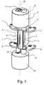
- the device includes a guide aperture 1 positioned vertically and arranged at the end of the feed section 2 via which the strip to be processed (not shown) is fed forward to the point where the bend is required and temporarily locked during the bending step.
- Figure 1 illustrates a configuration of the device in which the guide aperture 1 and the feed section 2 are oriented in a vertical direction, the device can be installed with guide aperture oriented in a horizontal direction.
- the bending tools 3 and 4 are retained alongside the guide aperture 1 by means of four brackets 5, 6, 7 and 8, two for each tool, which can rotate around axes S perpendicular to the feed direction of the strip.
- the brackets 5-8 are movable in pairs between a position in which the tools 3 and 4 are retained in position alongside the guide aperture 1 and a position in which the bending tools are released, for example during the bending phases or during their replacement.
- brackets 7 and 8 are in the position for locking the tool 4 beside the guide aperture 1, while the brackets 5 and 6 are in the position for release of the tool 3.
- Rotation of the brackets 5, 6, 7 and 8 is preferably performed, when required, by means of pneumatic actuators or, alternatively, by means of electric or electromechanical actuators or the like.
- the means for rotating the tools 3 and 4 include a lower hub 9 and an upper hub 10, arranged in opposite positions with respect to the predominant length of the guide aperture 1, which can rotate in a synchronised manner around their common axis M perpendicular to the feed direction of the strip.
- each of the hubs 9 and 10 houses engagement members 11, 12, 13 and 14 which translate in a direction parallel to the axis of rotation of the hubs.
- the movement of the engagement members 11-14 is also performed preferably by means of pneumatic actuators or, alternatively, by means of electric or electromechanical actuators or the like.
- the engagement members move between a tool disengagement position, in which the relative engagement members are retracted inside the hubs, and a tool engagement position, in which the respective engagement members are extracted from the hubs.
- the engagement members 11 and 12 for the tool 3 are in the extracted position and thus engage the ends of the tool 3 permitting rotation by the hubs 9 and 10, while the engagement members 13 and 14 for the tool 4 are in the disengaged position, retracted inside the hubs 9 and 10, thus avoiding rotation of the tool 4.
- Figure 2A shows a detail of the device of Figure 1 without the hubs 9 and 10 to illustrate more clearly the engagement members 11, 12, 13 and 14 in the same engagement and disengagement conditions as just described, i.e. with the engagement members 11 and 12 engaging the ends of the tool 3, while the ends of the tool 4 are disengaged from the engagement members 13 and 14.
- Figure 2B which is a top plan view of the lower hub 10, shows the engagement members 12 and 14 and the respective seats 22 and 24 in which the lower ends of the tools 3 and 4 are engaged respectively.
- the tool to be used in order for the strip passing through the feed section 2 of the guide aperture 1 to be processed, the tool to be used, according to whether the strip has to be bent to the right or the left, must be engaged by the corresponding engagement members to rotate and therefore necessarily be disengaged from the corresponding brackets, which will be rotated towards the outside of the device, so as to release the bending tool from the position alongside the guide aperture where it is retained while at rest.
- the engagement members 11, 12, 13 and 14 in the extracted position allow transmission of the rotation imparted by the motor to the hubs 9 and 10 to the tools 3 or 4 engaging the bending tool at their ends before it is released from the respective brackets 5, 6 or 7, 8 by means of rotation of the latter outwards.
- FIG. 4 shows the detail of the two tools 3 and 4 with the ends free of the engagement members, not shown for the sake of visual simplicity: the brackets 7 and 8 are closed, thus maintaining the tool 4 alongside the guide aperture 1, while the brackets 5 and 6 are in the open position, rotated towards the outside in order to completely release the tool 3 which can be easily replaced.
- the steps of bending the metallic strip by means of the present device include passing the strip through the guide aperture 1 and into its feed section 2 of suitable dimensions in relation to the thickness and size of the strip to be processed, sliding the latter to the point where the bend is required and temporary locking of the same during the actual bending operations. Said operations are performed by engaging the appropriate tool, according to whether the bend is required to the right or left, by means of the engagement members 11, 12, 13 and 14, opening the corresponding brackets and performing synchronised rotation of the hubs 9 and 10 at the required angle. Once the bending operation has been performed, the hubs rotate and return, to their starting position and the strip is moved to the next point to be bent.
- the tool just used is rotated again at the required angle, otherwise it is released, withdrawing the corresponding engagement members into the housings on the two hubs and closing the corresponding brackets; the other tool is then connected, extracting the corresponding engagement members and opening the relative brackets.
- the bends are performed successively according to the profile to be given to the strip.
- the tool 4 is disengaged as the engagement members 13 and 14 are retracted respectively in the hubs 10 and 9 and is positioned alongside the guide aperture 1 by means of the brackets 7 and 8 which are in the closed position. Bending is then performed with the tool 3 as illustrated in Figure 3A , with the hubs 9 and 10 rotating around the common axis M by the required angle in the direction indicated by the arrow L, and the tool 3 rotating integrally with the hubs 9 and 10 by means of the engagement members 11 and 12.
- the tool 4, being disengaged from the hubs 9 and 10 remains positioned alongside the guide aperture 1.
- the hubs 9 and 10 rotate in the opposite direction to the one indicated by the arrow L in Figure 3A , returning to the rest position illustrated in Figure 1 . At this point, if another bend has to be made in the same direction, the strip is moved forward again until it emerges from the guide aperture 1 for the required length, and the tool 3 is rotated again.
- the brackets 5 and 6 must be locked by the brackets 5 and 6 rotated towards the inside by means of an actuator, so that the tool 3 remains locked in position alongside the guide aperture 1 when disengagement occurs by retraction of the engagement members 11 and 12 into the hubs 9 and 10.
- the engagement members 13 and 14 are then extracted to engage the ends of the tool 4 to be used in the next bend, and the brackets 7 and 8 are opened by outward rotation of the device. After moving the strip forward for the required length, rotation of the hubs 9 and 10 begins around the common axis M in the direction indicated by the arrow R of Figure 3B , until completion of the rotation to the required angle.
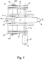
- Figure 5 shows schematically a possible embodiment of the rotation system of the bending tools 3 and 4 for the metallic strip W which is passed through the feed section 2 in the direction of the arrow F until it emerges from the guide aperture 1.
- the system is provided with one single motor 30, for example a gearmotor with shaft 31 on which the pulleys 32 and 33 are fitted.
- the shaft 31 rotates around an axis P, parallel to the axis M, which is obviously offset with respect to the feed section of the strip W.
- the hubs 9 and 10 are connected to respective shafts 109 and 110, with rotation axes coinciding with the axis M, on which the pulleys 42 and 43 are fitted. Synchronised transmission of the movement to the two hubs is provided for example by means of a first timing belt 52 stretched between the pulleys 32 and 42 and a second timing belt 53 stretched between the pulleys 33 and 43.
Description
- The present invention concerns a system for bending a metallic strip and, in particular, a device and a process for the production of for die-cutting blades starting from a continuous metallic strip which is shaped via successive bending steps and undergoes a final shearing step.
- The devices known in the art for bending metallic strips, in particular those intended for the production of die-cutting blades, generally include a system for feeding the continuous metallic strip through a guide aperture, in the vicinity of which one or more bending tools are located. In the majority of cases two bending tools are provided, one to bend the strip to the right (or upwards, for example) and the other to bend the strip to the left (or downwards, for example).
- The strip is fed forward through the guide aperture and temporarily stopped to perform the bending operation. The bending tool to be used is positioned near the guide aperture and then rotated to deform the strip as required to the right (or left) at a pre-set angle.
- A bending system with two tools is described, for example, in the United States patent no.
US-5870919 , in which the bending tools are retractable tools engaged in appropriate seats of coaxial supporting elements and rotated around their common axis. The bending tools can be used in a mutually exclusive way, i.e. keeping one tool in the work position (extended) while the other is kept in the rest position (retracted) and vice versa. - Another example of a bending system with two tools is described in the United States patent no.
US-6629442 , in which each tool is supported by a pair of coaxial supporting elements which can rotate around their common axis. The supporting elements of a pair are arranged alternately with those of the other pair and, consequently, at least two of them must have a seat for engagement of the bending tool supported, and a groove to permit the movement of the other one. - During the bending action, sliding occurs between the tool in contact with the strip and the strip itself. This results in considerable wear of the bending tools and therefore the need to replace the tools fairly frequently to ensure the necessary working accuracy.
- It should also be remembered that during the bending step, the tool is subject to a stress which increases proportionally to the bending angle required. The effects of wear on the tool are therefore considerable if strips have to be produced with particularly narrow bending angles.
- The known systems described above are particularly complex from the mechanical point of view and, consequently, replacement of the bending tools can be particularly time-consuming, thus affecting productivity.
- Independently of the wear on the tools, the feed section of the strip, with the relative guide aperture, also has to be changed whenever starting a new production phase with a metallic strip with dimensions or shape different from that of the strip processed previously.
- In general, the object of the present invention is to propose a device and a process for bending metallic strips which overcome the drawbacks of the known technique.
- A particular object of the present invention is to propose a device of the type described above which is mechanically simple to produce.
- A further object of the present invention is to propose a device of the type described above which makes the operations for replacing the bending tools and/or the strip feed section quick and easy.
- These objects are achieved according to the invention by means of a device for bending a metallic strip as claimed in
claim 1 and a relative bending process as claimed inclaim 8. Further peculiar aspects of the present invention are reported in the respective dependent claims. - According to a first aspect of the present invention, the device for bending a metallic strip includes at least one feed section to pass the strip through a guide aperture, at least one pair of bending tools which can rotate around at least one common rotation axis, and means for rotating the bending tools around the common rotation axis. The device advantageously includes controllable blocking means to lock the bending tools in positions mutually alongside the guide aperture when they are in the rest condition and to release at least one of the bending tools in the operating condition in which the bending is performed.
- When in the rest condition, the tools are always near the guide aperture, positioned alongside the latter. This position, in addition to favouring rapid performance of the bending operation, is particularly suitable for replacement of the tools. In fact, when the tools have to be replaced, the blocking means can be set to release both the worn tools. The new tools can thus be easily positioned and, by setting the blocking means to the locking position, they are ready to proceed with the strip bending operations. The blocking means for locking and releasing the bending tools preferably include brackets that can be rotated around an axis perpendicular to the feed direction of the strip. The blocking means can be operated in various ways, for example by using pneumatic or electric actuators or similar.
- To perform bending of the metallic strip, the bending tools are rotated by means which include controllable engagement members to engage or disengage the opposite ends of the bending tools.
- The means for rotating the bending tools include in particular at least two hubs opposed with respect to the guide aperture; said hubs can rotate around an axis perpendicular to the feed direction of the strip.
- The engagement members are housed in the hubs and are movable in translation along a direction parallel to the rotation axis of the hubs by means of pneumatic or electric actuators or similar. The engagement members move between a retracted position inside the hubs, and therefore disengaged from the bending tools, and a position in which they are extracted from the hubs, i.e. engaged with the ends of the bending tools.
- In the bending systems of the known art, in particular in the systems with retractable tools, each tool must necessarily have a slim section throughout its insertion length, as it must fit between the strip being bent and the end of the feed section. The same applies to the known systems with tools engaged in grooves of the rotating supports, which must have a reduced section at the ends in order not to weaken the rotating supports with excessively wide grooves.
- In the bending system according to the present invention, however, it is advantageously possible to use more hardy tools, i.e. tools with resistant section larger in the end portions which do not come into contact with the strip, while the portion that comes into contact with the strip can have a smaller section.
- The simplicity of the solution proposed by the present invention furthermore allows one single motor to be used to simultaneously drive both the hubs.
- When in the rest condition, the bending tools are locked in positions mutually alongside the guide aperture via the above-mentioned blocking means.
- To perform a bending operation, the strip is moved forward through the feed section until a pre-set length emerges from the guide aperture.
- After stopping the strip, the bending tool to be used is engaged at its ends by the engagement members which are appropriately extracted from the opposed hubs. In this way, the bending tool to be used rotates integrally with the opposed hubs in order to be rotated around the rotation axis common to both the tools.
- The blocking means combined with the bending tool to be used are then operated to release it from its locking position, while the other tool is kept locked in the rest condition.
- The bending tool to be used is then rotated by a rotation angle sufficient to bend the strip as required, and then re-set to the position corresponding to the rest condition. At this point, if the next bend is required in the same direction, the strip is moved forward again by a pre-set length and, once stopped, bending is performed by the same tool as illustrated previously.
- If on the other hand the next bend is required in the opposite direction, the tool which has already performed the bend is locked in the rest position by the respective blocking means and the respective engagement members are re-set to the retracted position inside the hubs, so as to disengage the tool that has just performed the bending operation from the rotation drive means. The next bend, in the opposite direction to the previous one, will therefore be performed by the other tool following the steps described previously.
- During the bending operations, each tool is activated in a mutually exclusive manner. Nevertheless, this does not exclude the possibility of operating both the tools simultaneously, for example if the strip is sheared by means of repeated bending in both directions, if necessary also exploiting a cut-off line previously provided in the strip.
- Further characteristics and advantages of the present invention will become more evident from the following description, provided by way of example with reference to the accompanying drawings, in which:
-
Figure 1 is a perspective schematic view of a possible embodiment of the device according to the present invention; -
Figure 2A is a view of the device ofFigure 1 without the hubs; -
Figure 2B is a plan view of one of the two hubs of the device ofFigure 1 ; -
Figures 3A and 3B are views of the device ofFigure 1 during bending, in one direction and in the opposite direction respectively; -
Figure 4 shows a detail of the device without the hubs and engagement members; and -
Figure 5 is a lateral schematic view illustrating some components of the device according to the present invention. - With reference first to
Figure 1 , the device for bending metallic strips according to the invention is illustrated as it is about to perform the bending operation in one of the two directions. - The device includes a
guide aperture 1 positioned vertically and arranged at the end of thefeed section 2 via which the strip to be processed (not shown) is fed forward to the point where the bend is required and temporarily locked during the bending step. AlthoughFigure 1 illustrates a configuration of the device in which theguide aperture 1 and thefeed section 2 are oriented in a vertical direction, the device can be installed with guide aperture oriented in a horizontal direction. - The
bending tools guide aperture 1 by means of fourbrackets tools guide aperture 1 and a position in which the bending tools are released, for example during the bending phases or during their replacement. - In
Figure 1 , by way of example, thebrackets tool 4 beside theguide aperture 1, while thebrackets tool 3. - Rotation of the
brackets - The means for rotating the
tools lower hub 9 and anupper hub 10, arranged in opposite positions with respect to the predominant length of theguide aperture 1, which can rotate in a synchronised manner around their common axis M perpendicular to the feed direction of the strip. - To engage or disengage rotation of the
tools hubs houses engagement members - The movement of the engagement members 11-14 is also performed preferably by means of pneumatic actuators or, alternatively, by means of electric or electromechanical actuators or the like. The engagement members move between a tool disengagement position, in which the relative engagement members are retracted inside the hubs, and a tool engagement position, in which the respective engagement members are extracted from the hubs.
- By way of example, again with reference to
Figure 1 , theengagement members tool 3 are in the extracted position and thus engage the ends of thetool 3 permitting rotation by thehubs engagement members tool 4 are in the disengaged position, retracted inside thehubs tool 4. -
Figure 2A shows a detail of the device ofFigure 1 without thehubs engagement members engagement members tool 3, while the ends of thetool 4 are disengaged from theengagement members - The view of
Figure 2B , which is a top plan view of thelower hub 10, shows theengagement members respective seats tools - At this point of the description, it will be clear that in order for the strip passing through the
feed section 2 of theguide aperture 1 to be processed, the tool to be used, according to whether the strip has to be bent to the right or the left, must be engaged by the corresponding engagement members to rotate and therefore necessarily be disengaged from the corresponding brackets, which will be rotated towards the outside of the device, so as to release the bending tool from the position alongside the guide aperture where it is retained while at rest. - The
engagement members hubs tools respective brackets - When the
engagement members hubs tools guide aperture 1 by thebrackets - With the device in this configuration, i.e. at rest, it is possible to easily replace the
tools tools feed section 2 if it is worn or if it has to be replaced according to the height of the strip to be processed subsequently. - Outward rotation of the
brackets guide aperture 1 since the corresponding engagement members do not engage its ends, as they are retracted in their respective housings obtained in the hubs.Figure 4 shows the detail of the twotools brackets tool 4 alongside theguide aperture 1, while thebrackets tool 3 which can be easily replaced. - The steps of bending the metallic strip by means of the present device include passing the strip through the
guide aperture 1 and into itsfeed section 2 of suitable dimensions in relation to the thickness and size of the strip to be processed, sliding the latter to the point where the bend is required and temporary locking of the same during the actual bending operations. Said operations are performed by engaging the appropriate tool, according to whether the bend is required to the right or left, by means of theengagement members hubs - For example, starting from the condition illustrated in
Figure 1 in which thetool 3 is the bending tool to be used, it can be seen that thetool 3 is engaged, theengagement members hubs brackets - The
tool 4, on the other hand, is disengaged as theengagement members hubs guide aperture 1 by means of thebrackets tool 3 as illustrated inFigure 3A , with thehubs tool 3 rotating integrally with thehubs engagement members tool 4, being disengaged from thehubs guide aperture 1. Once bending has been performed, thehubs Figure 3A , returning to the rest position illustrated inFigure 1 . At this point, if another bend has to be made in the same direction, the strip is moved forward again until it emerges from theguide aperture 1 for the required length, and thetool 3 is rotated again. - If on the other hand the bend has to be made in the opposite direction with respect to the previous one for which the
tool 3 was used, the latter must be locked by thebrackets tool 3 remains locked in position alongside theguide aperture 1 when disengagement occurs by retraction of theengagement members hubs engagement members tool 4 to be used in the next bend, and thebrackets hubs Figure 3B , until completion of the rotation to the required angle.Figure 5 shows schematically a possible embodiment of the rotation system of thebending tools feed section 2 in the direction of the arrow F until it emerges from theguide aperture 1. The system is provided with onesingle motor 30, for example a gearmotor withshaft 31 on which thepulleys 32 and 33 are fitted. Theshaft 31 rotates around an axis P, parallel to the axis M, which is obviously offset with respect to the feed section of the strip W. - The
hubs respective shafts pulleys first timing belt 52 stretched between thepulleys 32 and 42 and asecond timing belt 53 stretched between thepulleys - Other means for transmission of the movement can be used just as effectively between the
shaft 31 and theshafts
Claims (10)
- A device for bending a metallic strip, including at least one feed section (2) to pass said strip through a guide aperture (1), at least one pair of bending tools (3, 4) which can be rotated around at least one common rotation axis (S), and means for rotating said bending tools (3, 4) around said at least one common rotation axis (M), wherein controllable blocking means (5, 6, 7, 8) are provided to lock said bending tools (3, 4) mutually alongside said guide aperture (1) when they are in the rest condition and to release at least one of said bending tools (3, 4) to the operating condition in which the bending is performed, characterised in that said means for rotating said bending tools (3, 4) include controllable engagement members (11, 12, 13, 14) to engage the opposite ends of a bending tool to be used for performing a bending operation or disengage the opposite ends of a bending tool when the tool is kept locked in the rest condition.
- The device as claimed in claim 1, wherein said blocking means (5, 6, 7, 8) to lock and release said bending tools (3, 4) include brackets which can be rotated around an axis (S) perpendicular to the feed direction of said strip.
- The device as claimed in claim 1, wherein said means for rotating said bending tools (3, 4) include at least two hubs (9, 10) opposed with respect to said guide aperture (1) and which can rotate around an axis (M) perpendicular to the feed direction of said strip.
- The device as claimed in claim 3, wherein said engagement members (11, 12, 13, 14) are housed in said hubs (9, 10) and translate in a direction parallel to the rotation axis of said hubs (9, 10) between a retracted position inside said hubs (9, 10), in the disengaged condition from said bending tools (3, 4), and a position extracted from said hubs (9, 10), in the engaged condition with said bending tools (3, 4).
- The device as claimed in claim 4, wherein said hubs (9, 10) are simultaneously rotated by one single motor (10).
- A machine for the production of die-cutting blades starting from a continuous metallic strip which is shaped by means of successive bending steps and undergoes a final shearing step, characterised by including a device as claimed in any one of claims 1 to 5 and wherein said guide aperture (1) in said feed section (2) is oriented in a horizontal direction.
- A machine for the production of die-cutting blades starting from a continuous metallic strip which is shaped by means of successive bending steps and undergoes a final shearing step, characterised by including a device as claimed in any one of claims 1 to 5 and wherein said guide aperture (1) in said feed section (2) is oriented in a vertical direction.
- A process for bending a metallic strip, wherein said strip is passed through a feed section (2) to a guide aperture (1) and wherein said strip is bent by means of at least one pair of bending tools (3, 4) positioned near said guide aperture (1) and which can be rotated around at least one common rotation axis (M), characterised by including the steps of:i) at the rest condition, keeping said tools (3, 4) locked in position mutually alongside said guide aperture (1) by means of controllable blocking means (5, 6, 7, 8);ii) engaging a bending tool to be used at its ends by engagement members to make it integral with means for rotating said bending tools (3, 4) around said at least one common rotation axis (M);iii) operating said blocking means (5, 6, 7, 8) associated with said bending tool to release it from its locking position while the other of said bending tools (3, 4) is blocked in its rest position;iv) rotating said bending tool by a rotation angle sufficient to give said strip the required bend;v) re-setting said bending tool to its rest position;vi) operating the blocking means (5, 6, 7, 8) associated with said bending tool to re-lock it in its rest position; andvii) disengaging the engagement members from the opposite ends of said bending tool to disengage it from said rotation means.
- The process as claimed in claim 8 wherein, before said step iv), said strip is moved forward through said feed section (2) until it emerges from said guide aperture (1) for a pre-set length.
- The process as claimed in claim 8 or 9 wherein, after said step v), said strip is moved forward again for a pre-set length and the process restarts from said step iv).
Applications Claiming Priority (1)
| Application Number | Priority Date | Filing Date | Title |
|---|---|---|---|
| PCT/IT2008/000348 WO2009144748A1 (en) | 2008-05-27 | 2008-05-27 | System for bending a metallic strip |
Publications (2)
| Publication Number | Publication Date |
|---|---|
| EP2285509A1 EP2285509A1 (en) | 2011-02-23 |
| EP2285509B1 true EP2285509B1 (en) | 2017-05-10 |
Family
ID=40256966
Family Applications (1)
| Application Number | Title | Priority Date | Filing Date |
|---|---|---|---|
| EP08789962.1A Active EP2285509B1 (en) | 2008-05-27 | 2008-05-27 | System for bending a metallic strip |
Country Status (3)
| Country | Link |
|---|---|
| US (1) | US8720245B2 (en) |
| EP (1) | EP2285509B1 (en) |
| WO (1) | WO2009144748A1 (en) |
Cited By (1)
| Publication number | Priority date | Publication date | Assignee | Title |
|---|---|---|---|---|
| CN114178359A (en) * | 2021-12-03 | 2022-03-15 | 湖南骏昊智能科技有限公司 | Bending mechanism and knife bending machine |
Family Cites Families (4)
| Publication number | Priority date | Publication date | Assignee | Title |
|---|---|---|---|---|
| KR0182069B1 (en) * | 1995-06-22 | 1999-04-01 | 송병준 | Bent-up system of cutting blade |
| KR100388542B1 (en) * | 2000-12-01 | 2003-06-25 | 박홍순 | Cutting blade bending apparatus capable of performing accurate acute angle |
| US7387009B2 (en) * | 2005-03-24 | 2008-06-17 | Kevin Kane | Automated bending machine |
| JP4435035B2 (en) * | 2005-05-27 | 2010-03-17 | 聰長 占部 | Cutting device for both ends of blade in automatic bending machine with steel rule |
-
2008
- 2008-05-27 EP EP08789962.1A patent/EP2285509B1/en active Active
- 2008-05-27 WO PCT/IT2008/000348 patent/WO2009144748A1/en active Application Filing
- 2008-05-27 US US12/993,016 patent/US8720245B2/en active Active
Non-Patent Citations (1)
| Title |
|---|
| None * |
Cited By (1)
| Publication number | Priority date | Publication date | Assignee | Title |
|---|---|---|---|---|
| CN114178359A (en) * | 2021-12-03 | 2022-03-15 | 湖南骏昊智能科技有限公司 | Bending mechanism and knife bending machine |
Also Published As
| Publication number | Publication date |
|---|---|
| US8720245B2 (en) | 2014-05-13 |
| EP2285509A1 (en) | 2011-02-23 |
| US20110107809A1 (en) | 2011-05-12 |
| WO2009144748A1 (en) | 2009-12-03 |
Similar Documents
| Publication | Publication Date | Title |
|---|---|---|
| EP3624962B1 (en) | Bending machine for metal sheets | |
| EP1314584A1 (en) | Bead releasing and removing head for a tire-fitting machine | |
| EP2514611A1 (en) | Method and device for mounting a pneumatic tyre with the use of a robot | |
| EP3027332B1 (en) | Bending tool system | |
| EP2691190B1 (en) | Mechanism for moving the blade holder of a panel bender for bending sheet metal sheets | |
| TW201603906A (en) | Sheet metal bending machine | |
| WO2013132429A1 (en) | Method and system for bending spacers | |
| KR20150139496A (en) | Device for bending profile sections such as tubes | |
| EP2599755A1 (en) | Machine for performing cutting operations on laminated glass plates | |
| EP1998909B1 (en) | Device and method for bending a metallic strip | |
| EP2285509B1 (en) | System for bending a metallic strip | |
| WO2014087328A1 (en) | Improved metal pipes bending machine, both to the right and to the left with respect to the direction of introduction of the pipe | |
| EP2543618A1 (en) | Elevator door coupling apparatus | |
| EP2508331B1 (en) | Device for manufacturing a vehicle tyre | |
| EP3248706A1 (en) | Rolling machine for forming impressions on cylindrical bodies and method for substituting a forming roller of such rolling machine | |
| EP2374584A1 (en) | Device for cutting a food product | |
| EP2374581B1 (en) | Device for cutting a food product | |
| EP3025802B1 (en) | Device and method for pressure rolling workpieces | |
| JP6661470B2 (en) | Transfer device for multi-stage forging press | |
| JP6661471B2 (en) | Transfer device for multi-stage forging press | |
| EP2982455A1 (en) | Apparatus and method for bending tubular components | |
| ITUD20110116A1 (en) | MACHINE FOR BENDING METAL BARS AND ITS PROCEDURE | |
| EP3487644B1 (en) | Drawing carriage for a drawing machine, and drawing machine | |
| DE102019131338B3 (en) | Positioning system and method for creating vehicle tires | |
| CN114769445B (en) | Guiding feeding device and straightening equipment |
Legal Events
| Date | Code | Title | Description |
|---|---|---|---|
| PUAI | Public reference made under article 153(3) epc to a published international application that has entered the european phase |
Free format text: ORIGINAL CODE: 0009012 |
|
| 17P | Request for examination filed |
Effective date: 20101223 |
|
| AK | Designated contracting states |
Kind code of ref document: A1 Designated state(s): AT BE BG CH CY CZ DE DK EE ES FI FR GB GR HR HU IE IS IT LI LT LU LV MC MT NL NO PL PT RO SE SI SK TR |
|
| AX | Request for extension of the european patent |
Extension state: AL BA MK RS |
|
| DAX | Request for extension of the european patent (deleted) | ||
| GRAP | Despatch of communication of intention to grant a patent |
Free format text: ORIGINAL CODE: EPIDOSNIGR1 |
|
| INTG | Intention to grant announced |
Effective date: 20161125 |
|
| GRAJ | Information related to disapproval of communication of intention to grant by the applicant or resumption of examination proceedings by the epo deleted |
Free format text: ORIGINAL CODE: EPIDOSDIGR1 |
|
| GRAR | Information related to intention to grant a patent recorded |
Free format text: ORIGINAL CODE: EPIDOSNIGR71 |
|
| GRAS | Grant fee paid |
Free format text: ORIGINAL CODE: EPIDOSNIGR3 |
|
| GRAA | (expected) grant |
Free format text: ORIGINAL CODE: 0009210 |
|
| INTC | Intention to grant announced (deleted) | ||
| AK | Designated contracting states |
Kind code of ref document: B1 Designated state(s): AT BE BG CH CY CZ DE DK EE ES FI FR GB GR HR HU IE IS IT LI LT LU LV MC MT NL NO PL PT RO SE SI SK TR |
|
| INTG | Intention to grant announced |
Effective date: 20170331 |
|
| REG | Reference to a national code |
Ref country code: GB Ref legal event code: FG4D |
|
| REG | Reference to a national code |
Ref country code: AT Ref legal event code: REF Ref document number: 891751 Country of ref document: AT Kind code of ref document: T Effective date: 20170515 Ref country code: CH Ref legal event code: EP |
|
| REG | Reference to a national code |
Ref country code: IE Ref legal event code: FG4D |
|
| REG | Reference to a national code |
Ref country code: DE Ref legal event code: R096 Ref document number: 602008050233 Country of ref document: DE |
|
| REG | Reference to a national code |
Ref country code: NL Ref legal event code: MP Effective date: 20170510 |
|
| REG | Reference to a national code |
Ref country code: LT Ref legal event code: MG4D |
|
| REG | Reference to a national code |
Ref country code: AT Ref legal event code: MK05 Ref document number: 891751 Country of ref document: AT Kind code of ref document: T Effective date: 20170510 |
|
| PG25 | Lapsed in a contracting state [announced via postgrant information from national office to epo] |
Ref country code: LT Free format text: LAPSE BECAUSE OF FAILURE TO SUBMIT A TRANSLATION OF THE DESCRIPTION OR TO PAY THE FEE WITHIN THE PRESCRIBED TIME-LIMIT Effective date: 20170510 Ref country code: AT Free format text: LAPSE BECAUSE OF FAILURE TO SUBMIT A TRANSLATION OF THE DESCRIPTION OR TO PAY THE FEE WITHIN THE PRESCRIBED TIME-LIMIT Effective date: 20170510 Ref country code: ES Free format text: LAPSE BECAUSE OF FAILURE TO SUBMIT A TRANSLATION OF THE DESCRIPTION OR TO PAY THE FEE WITHIN THE PRESCRIBED TIME-LIMIT Effective date: 20170510 Ref country code: FI Free format text: LAPSE BECAUSE OF FAILURE TO SUBMIT A TRANSLATION OF THE DESCRIPTION OR TO PAY THE FEE WITHIN THE PRESCRIBED TIME-LIMIT Effective date: 20170510 Ref country code: GR Free format text: LAPSE BECAUSE OF FAILURE TO SUBMIT A TRANSLATION OF THE DESCRIPTION OR TO PAY THE FEE WITHIN THE PRESCRIBED TIME-LIMIT Effective date: 20170811 Ref country code: NO Free format text: LAPSE BECAUSE OF FAILURE TO SUBMIT A TRANSLATION OF THE DESCRIPTION OR TO PAY THE FEE WITHIN THE PRESCRIBED TIME-LIMIT Effective date: 20170810 Ref country code: HR Free format text: LAPSE BECAUSE OF FAILURE TO SUBMIT A TRANSLATION OF THE DESCRIPTION OR TO PAY THE FEE WITHIN THE PRESCRIBED TIME-LIMIT Effective date: 20170510 |
|
| PG25 | Lapsed in a contracting state [announced via postgrant information from national office to epo] |
Ref country code: LV Free format text: LAPSE BECAUSE OF FAILURE TO SUBMIT A TRANSLATION OF THE DESCRIPTION OR TO PAY THE FEE WITHIN THE PRESCRIBED TIME-LIMIT Effective date: 20170510 Ref country code: SE Free format text: LAPSE BECAUSE OF FAILURE TO SUBMIT A TRANSLATION OF THE DESCRIPTION OR TO PAY THE FEE WITHIN THE PRESCRIBED TIME-LIMIT Effective date: 20170510 Ref country code: NL Free format text: LAPSE BECAUSE OF FAILURE TO SUBMIT A TRANSLATION OF THE DESCRIPTION OR TO PAY THE FEE WITHIN THE PRESCRIBED TIME-LIMIT Effective date: 20170510 Ref country code: IS Free format text: LAPSE BECAUSE OF FAILURE TO SUBMIT A TRANSLATION OF THE DESCRIPTION OR TO PAY THE FEE WITHIN THE PRESCRIBED TIME-LIMIT Effective date: 20170910 Ref country code: PL Free format text: LAPSE BECAUSE OF FAILURE TO SUBMIT A TRANSLATION OF THE DESCRIPTION OR TO PAY THE FEE WITHIN THE PRESCRIBED TIME-LIMIT Effective date: 20170510 Ref country code: BG Free format text: LAPSE BECAUSE OF FAILURE TO SUBMIT A TRANSLATION OF THE DESCRIPTION OR TO PAY THE FEE WITHIN THE PRESCRIBED TIME-LIMIT Effective date: 20170810 |
|
| REG | Reference to a national code |
Ref country code: CH Ref legal event code: PL |
|
| PG25 | Lapsed in a contracting state [announced via postgrant information from national office to epo] |
Ref country code: SK Free format text: LAPSE BECAUSE OF FAILURE TO SUBMIT A TRANSLATION OF THE DESCRIPTION OR TO PAY THE FEE WITHIN THE PRESCRIBED TIME-LIMIT Effective date: 20170510 Ref country code: RO Free format text: LAPSE BECAUSE OF FAILURE TO SUBMIT A TRANSLATION OF THE DESCRIPTION OR TO PAY THE FEE WITHIN THE PRESCRIBED TIME-LIMIT Effective date: 20170510 Ref country code: EE Free format text: LAPSE BECAUSE OF FAILURE TO SUBMIT A TRANSLATION OF THE DESCRIPTION OR TO PAY THE FEE WITHIN THE PRESCRIBED TIME-LIMIT Effective date: 20170510 Ref country code: CZ Free format text: LAPSE BECAUSE OF FAILURE TO SUBMIT A TRANSLATION OF THE DESCRIPTION OR TO PAY THE FEE WITHIN THE PRESCRIBED TIME-LIMIT Effective date: 20170510 Ref country code: DK Free format text: LAPSE BECAUSE OF FAILURE TO SUBMIT A TRANSLATION OF THE DESCRIPTION OR TO PAY THE FEE WITHIN THE PRESCRIBED TIME-LIMIT Effective date: 20170510 |
|
| REG | Reference to a national code |
Ref country code: DE Ref legal event code: R097 Ref document number: 602008050233 Country of ref document: DE |
|
| REG | Reference to a national code |
Ref country code: IE Ref legal event code: MM4A |
|
| PG25 | Lapsed in a contracting state [announced via postgrant information from national office to epo] |
Ref country code: CH Free format text: LAPSE BECAUSE OF NON-PAYMENT OF DUE FEES Effective date: 20170531 Ref country code: LI Free format text: LAPSE BECAUSE OF NON-PAYMENT OF DUE FEES Effective date: 20170531 |
|
| PLBE | No opposition filed within time limit |
Free format text: ORIGINAL CODE: 0009261 |
|
| STAA | Information on the status of an ep patent application or granted ep patent |
Free format text: STATUS: NO OPPOSITION FILED WITHIN TIME LIMIT |
|
| PG25 | Lapsed in a contracting state [announced via postgrant information from national office to epo] |
Ref country code: LU Free format text: LAPSE BECAUSE OF NON-PAYMENT OF DUE FEES Effective date: 20170527 |
|
| 26N | No opposition filed |
Effective date: 20180213 |
|
| GBPC | Gb: european patent ceased through non-payment of renewal fee |
Effective date: 20170810 |
|
| REG | Reference to a national code |
Ref country code: BE Ref legal event code: MM Effective date: 20170531 |
|
| PG25 | Lapsed in a contracting state [announced via postgrant information from national office to epo] |
Ref country code: IE Free format text: LAPSE BECAUSE OF NON-PAYMENT OF DUE FEES Effective date: 20170527 |
|
| REG | Reference to a national code |
Ref country code: FR Ref legal event code: ST Effective date: 20180404 |
|
| PG25 | Lapsed in a contracting state [announced via postgrant information from national office to epo] |
Ref country code: SI Free format text: LAPSE BECAUSE OF FAILURE TO SUBMIT A TRANSLATION OF THE DESCRIPTION OR TO PAY THE FEE WITHIN THE PRESCRIBED TIME-LIMIT Effective date: 20170510 |
|
| PG25 | Lapsed in a contracting state [announced via postgrant information from national office to epo] |
Ref country code: GB Free format text: LAPSE BECAUSE OF NON-PAYMENT OF DUE FEES Effective date: 20170810 |
|
| PG25 | Lapsed in a contracting state [announced via postgrant information from national office to epo] |
Ref country code: BE Free format text: LAPSE BECAUSE OF NON-PAYMENT OF DUE FEES Effective date: 20170531 Ref country code: FR Free format text: LAPSE BECAUSE OF NON-PAYMENT OF DUE FEES Effective date: 20170710 |
|
| PG25 | Lapsed in a contracting state [announced via postgrant information from national office to epo] |
Ref country code: MT Free format text: LAPSE BECAUSE OF NON-PAYMENT OF DUE FEES Effective date: 20170527 |
|
| PG25 | Lapsed in a contracting state [announced via postgrant information from national office to epo] |
Ref country code: HU Free format text: LAPSE BECAUSE OF FAILURE TO SUBMIT A TRANSLATION OF THE DESCRIPTION OR TO PAY THE FEE WITHIN THE PRESCRIBED TIME-LIMIT; INVALID AB INITIO Effective date: 20080527 Ref country code: MC Free format text: LAPSE BECAUSE OF FAILURE TO SUBMIT A TRANSLATION OF THE DESCRIPTION OR TO PAY THE FEE WITHIN THE PRESCRIBED TIME-LIMIT Effective date: 20170510 |
|
| PG25 | Lapsed in a contracting state [announced via postgrant information from national office to epo] |
Ref country code: CY Free format text: LAPSE BECAUSE OF NON-PAYMENT OF DUE FEES Effective date: 20170510 |
|
| PG25 | Lapsed in a contracting state [announced via postgrant information from national office to epo] |
Ref country code: TR Free format text: LAPSE BECAUSE OF FAILURE TO SUBMIT A TRANSLATION OF THE DESCRIPTION OR TO PAY THE FEE WITHIN THE PRESCRIBED TIME-LIMIT Effective date: 20170510 |
|
| PG25 | Lapsed in a contracting state [announced via postgrant information from national office to epo] |
Ref country code: PT Free format text: LAPSE BECAUSE OF FAILURE TO SUBMIT A TRANSLATION OF THE DESCRIPTION OR TO PAY THE FEE WITHIN THE PRESCRIBED TIME-LIMIT Effective date: 20170510 |
|
| PGFP | Annual fee paid to national office [announced via postgrant information from national office to epo] |
Ref country code: IT Payment date: 20230515 Year of fee payment: 16 Ref country code: DE Payment date: 20230525 Year of fee payment: 16 |
|
| P01 | Opt-out of the competence of the unified patent court (upc) registered |
Effective date: 20230828 |