EP2284650A2 - Methods and apparatus for power allocation in a storage system - Google Patents
Methods and apparatus for power allocation in a storage system Download PDFInfo
- Publication number
- EP2284650A2 EP2284650A2 EP10153419A EP10153419A EP2284650A2 EP 2284650 A2 EP2284650 A2 EP 2284650A2 EP 10153419 A EP10153419 A EP 10153419A EP 10153419 A EP10153419 A EP 10153419A EP 2284650 A2 EP2284650 A2 EP 2284650A2
- Authority
- EP
- European Patent Office
- Prior art keywords
- power
- controller
- devices
- sas
- sata
- Prior art date
- Legal status (The legal status is an assumption and is not a legal conclusion. Google has not performed a legal analysis and makes no representation as to the accuracy of the status listed.)
- Ceased
Links
Images
Classifications
-
- G—PHYSICS
- G06—COMPUTING OR CALCULATING; COUNTING
- G06F—ELECTRIC DIGITAL DATA PROCESSING
- G06F1/00—Details not covered by groups G06F3/00 - G06F13/00 and G06F21/00
- G06F1/26—Power supply means, e.g. regulation thereof
- G06F1/266—Arrangements to supply power to external peripherals either directly from the computer or under computer control, e.g. supply of power through the communication port, computer controlled power-strips
Definitions
- a shared power source is used to power a number of devices of the system under control of a common control unit.
- a storage controller may controllably coordinate the application power from a power supply to each of a plurality of storage devices.
- each of the storage devices may be, for example, a rotating disk drive.
- Such devices may utilize minimal power when initially applied but may then consume substantially more power as the disk drive's motor starts to spin the rotating storage media within the disk drive. Though the disk drive consume less power once the motor has reached the desired rotational speed (i.e., in steady state operation), for a burst of time the disk drive may require substantially more power to commence and complete its initialization.
- a controlling device coupled with the storage devices may utilize command structures and/or protocol primitives/sequences to control and sequence the "spin-up" of each storage device under its control.
- Such controlling devices may include, for example, a storage controller (e.g., SCSI, SAS, or SATA controller), a SAS expander, a SATA port multiplier, etc.
- the controlling device may, for example, limit the number of SCSI disk drives enabled to spin-up at any given point in time until eventually all disk drives are started and spinning.
- a SCSI/SAS storage controller may limit the spin-up power requirements for the plurality of disk drives under its control.
- the storage controller has no knowledge of how long the SCSI disk drive may require the added power to complete initialization.
- present SCSI/SAS storage controllers presume a worst case scenario allowing a maximum possible time duration for the initialization of each SCSI disk drive coupled thereto. This solution may cause a significant, unnecessary delay in the initialization of the storage system and hence delays in access to the storage system by attached host systems.
- the storage devices may be coupled to multiple controlling devices or may autonomously change their power consumptions status. Further, the controlling device may not even be coupled in the same power domain to allow it to have knowledge of the available power status of the storage devices. In such cases, a simple command structure may not suffice to allow the controlling device to coordinate and sequence the power consumption of the storage devices.
- SATA Serial Advanced Technology Attachment
- SATA controllers and port multipliers as controlling devices may lack the ability to effectively coordinate the application of power to SATA storage devices coupled thereto.
- Present storage systems utilizing SATA disk drives therefore typically provide a significantly oversized (excess capacity) power supply to allow for worst case power consumption if all SATA.
- Such an oversized power supply adds cost/complexity to the storage system.
- the present invention solves the above and other problems, thereby advancing the state of the useful arts, by providing methods and systems for managing power allocation from a common power supply to a plurality of devices under control of a controller.
- the controller and devices exchange messages to control allocation of power to the plurality of devices.
- a device transmits a power request message to the controller.
- the controller maintains an indicator of presently available power capacity from the power supply. If the presently available power capacity is sufficient to grant the device's request, a power grant message is transmitted from the controller to the requesting device and the presently available power capacity is updated to reflect the allocation.
- a power status message may be sent from a device to the controller indicating a change in the power consumption of the device. For example, when a device completes its use of additional power, a power status message may be sent to the controller to indicate that the previously allocated additional power is no longer required.
- the controller may be a SAS/SATA controller and the devices may be SAS/SATA storage devices such as rotating disk drives.
- a storage device requires additional power (e.g., to spin-up the motor for the rotating storage medium), it requests additional power from the controller.
- the controller grants the additional power, the storage device may then spin-up the motor.
- the device may transmit a power status message to the controller to permit the controller to re-allocate the freed additional power capacity.
- the messages exchanged may be SAS/SATA frames and/or primitives.
- a method in a system comprising a controller and a plurality of devices coupled to the controller.
- the method manages power applied to each of the plurality of devices communicatively coupled to the controller.
- the method includes allocating, within the controller, an initial power amount to each of the plurality of devices and receiving a power request message in the controller from a device.
- the method determines, within the controller, whether sufficient power capacity is presently available. Responsive to determining that sufficient power capacity is presently available, the method then includes allocating, within the controller, the additional power to the device, and transmitting a power grant message from the controller to the device to grant the device permission to use the allocated additional power.
- the storage system comprising a storage controller coupled to a plurality of storage devices using a communication medium and protocol.
- the method operable in the storage controller.
- the method includes determining a total available power capacity, allocating an initial power amount to each of the plurality of storage devices, and adjusting the total available power capacity based on the sum of the initial power amount allocated to each of the plurality of storage devices.
- the method receives a power request message from a requesting device of the plurality of devices requesting an additional power amount.
- the method determines whether the total available power capacity is sufficient to provide the requested additional power amount.
- the method Responsive to a determination that the total available power capacity is sufficient to provide the requested additional power amount, the method then includes allocating the requested additional power amount for the requesting device, transmitting a power grant message to the requesting device, and adjusting the total available power capacity based on the requested additional power amount.
- Yet another aspect hereof provides system comprising a power supply, a plurality of devices each device coupled to receive power from the power supply and each adapted to require varying amounts of power during operation, and a SAS controller communicatively coupled with each of the plurality of devices.
- the controller adapted to exchange SAS information with one or more devices of the plurality of devices to manage the consumption of power from the power supply consumed by the one or more devices.
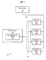
- FIG. 1 is a block diagram of an exemplary system adapted in accordance with features and aspects hereof to manage power allocation to a plurality of devices coupled to a common controller and a common power supply source.
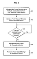
- FIG. 2 is a flowchart describing an exemplary method in accordance with features and aspects hereof to manage allocation of power for a plurality of devices coupled to a controller.
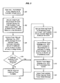
- FIG. 3 is a flowchart describing another exemplary method in accordance with features and aspects hereof to manage allocation of power for a plurality of devices coupled to a controller.
- FIG. 1 is a block diagram of a system 100 enhanced in accordance with features and aspects hereof to manage power consumption by one or more devices 106.1 through 106.4 coupled to the controller.
- System 100 may include a power supply 108, a SAS controller 102, and one or more devices 106.1 through 106.4 each coupled with the power supply 108 and coupled with the SAS controller 102.
- Each device 106.1 through 106.4 may receive one or more voltage levels via signal path 152 from power supply 108.
- SAS controller 102 may include power management module 104 coupled to communicate with SAS devices 106.1 through 106.4 via paths 150.
- storage controller 102 may be any suitable controlling device including, for example, SAS/SATA storage controllers, SAS expanders, SATA port multipliers, etc.
- devices 106.1 through 106.4 may be SAS/SATA devices such as disk drives or other storage devices.
- communication path 150 represents any suitable SAS or SATA standards compliant communication medium.
- Power management module 104 communicates with devices 106.1 through 106.4 to manage the power consumption of each of the devices sharing the common power source from power supply 108. More specifically, power management module 104 exchanges information (e.g., control and status information) with devices 106.1 through 106.4 to manage the amount of power consumed by any of devices 106.1 through 106.4 and/or the timing or sequencing of the power consumption by the various devices 106.1 through 106.4.
- information e.g., control and status information
- SAS controller 102 may be any suitable computing device acting in the role of a SAS controller communicating with one or more SAS/SATA devices 106.1 through 106.4.
- SAS controller 102 may be a SAS initiator.
- SAS controller 102 may be a SAS expander.
- power management module 104 may be suitably programmed instructions executed by a general or special purpose processor within SAS controller 102.
- power management module 104 may be implemented as customized circuits and/or combinations of custom circuits and suitably programmed instructions.
- power management module 104 represents any suitable control structure for interacting with the devices 106.1 through 106.4 to manage the power consumption by the various devices.
- the information exchanged between power management module 104 and the various devices 106.1 through 106.4 may be SAS frames, SAS primitives, and/or SATA frames.
- the SAS/SATA information so exchanged may include a request message from a device 106.1 through 106.4 directed to the power management module 104 within SAS controller 102 requesting an allocation of power for the device.
- the request message may indicate an amount of additional power required by the device. For example, during spin-up operation of a rotating disk drive, additional power is required by the disk drive until the rotating media reaches steady-state controlled speed. In such a case, the device would issue a request message to the power management module 104 of SAS controller 102 requesting an allocation of additional power for operation of the device requesting device.
- a grant message may be transmitted from the SAS controller 102 when it determines that sufficient power capacity is presently available to satisfy the requesting device's power request message.
- the grant message may indicate the particular amount of power allocated to the requesting device if less than the requested amount is presently available.
- the grant message may indicate the duration of time during which the requesting device may utilize the allocated additional power.
- Still other embodiments may utilize a grant message to indicate particular amount of additional power and/or duration of that additional power for each of multiple voltage levels available from the power supply 108.
- a power status message may be generated by the device 106.1 through 106.4 and transmitted back to the SAS controller 102.
- a power status message may indicate, for example, a change in the status of the corresponding device as regards its power consumption.
- a power status message may be transmitted from the device to the storage controller when the previously requested and granted additional power is no longer required. In such a case, the storage controller may return the previously allocated power capacity to accumulated total of available power capacity for potential allocation to other devices.
- System 100 of FIG. 1 and equivalent structures noted above, improve upon prior techniques by allowing the SAS controller 102 (through its power management module 104) to more precisely and rapidly sequence the power up (spin-up) processing of each of multiple storage devices 106.1 through 106.4 coupled to the SAS controller 102.
- the controller 102 may receive requests from each device when the device is ready for spin-up processing and may then sequence the granting of power to each requesting device so as to maximize utilization of the available power from power supply 108 while assuring that no more than the available capacity power capacity is ever granted.
- the power status messages received by the staff controller from devices 106.1 through 106.4 may permit the SAS controller to more tightly control the timing of the sequence of spin-up of multiple disk drives (devices 106.1 through 106.4).
- the storage controller need not wait, as presently practiced, for a maximum delay before presuming the device has completed its spin-up processing.
- the storage controller 102 may permit another device to commence spin-up processing immediately upon sensing completion from the power status message of a prior device completing its spin-up processing.
- the management of power allocation by power management module 104 may be implemented in one exemplary embodiment through use of a counter function/structure in the power management module 104 of controller 102.
- a counter may initialized to indicate the maximum available power.
- Multiple counters may also be initialized representing the maximum power available for each of multiple voltage levels supplied by the power supply 108.
- the initial, maximum available power (for each voltage level provided by the supply 108) may be configured as a parameter in the controller 102 at time of manufacture of system 100, may be dynamically configured by an administrative user of system 100, or may be dynamically determined by exchanges between the controller 102 and the supply 108 via an appropriate data path therebetween (not shown).
- the counter/counters are decremented by the amount of power granted to a device.
- the counter/counters may be appropriately incremented to indicate reduced power consumption and thus allowing the presently available power to be allocated to other devices without waiting for a maximum timeout for use of the additional power by a device.
- the counter/counters are updated in response to the various messages exchanged to maintain a record of the presently available power from the supply 108.
- FIG. 2 is a flowchart describing an exemplary embodiment in accordance with features and aspects hereof to permit improved management of power allocation for a plurality of devices coupled to a common power supply source and a storage controller.
- the method of FIG. 2 may be operable, for example, in a system such as a system 100 of FIG. 1 . More specifically, the method of FIG. 2 may be performed by a power management module operable within a storage controller of the system as exemplified in FIG. 1 .
- Step 200 first accounts for an initial power allocation for each attached device from the total available power capacity.
- a counter may be initialized to represent the total available power from the power supply. There may one counter for each available voltage level generated by the power supply.
- the total available power capacity (e.g., for each voltage level) may be predetermined and preconfigured as noted above and/or may be dynamically determined by communications with the power supply.
- An initial allocation of power for each of the devices accounts for the minimal power requirements for each device to allow control electronics of each device to begin processing to permit communications with the controller. In the case of a disk drive device coupled to the controller, the initial power allocation would typically not include the additional power capacity required to spin-up the rotating disc media. Rather, the initial power allocation may account only for the computational logic that controls the device to enable minimal communications with the storage controller or only for normal steady state operation of the device following initial spin-up.
- Step 202 then receives a power request message from an attached device.
- the message may be encoded as a SAS/SATA frame and/or primitive.
- the power request message may represent a standardized request for allocation of a standardized amount of power and need not specify the specific amount of power required.
- the standardized amount of power may be predetermined and preconfigured by the system designer/manufacturer or by an administrative user.
- the power request message may specify the amount of additional power being requested for further operations of the device.
- the power request message may indicate a particular amount of power required for each of multiple voltage levels provided by the power supply.
- Step 204 determines whether there is presently sufficient available power capacity from the power supply to satisfy the additional power request received from an attached device. As noted above, where the power request message indicates a specific amount of power from each of multiple available voltage levels, step 204 determines whether the requested additional capacity is available from all identified voltage levels. If not, processing continues looping on step 204 until sufficient available capacity is restored. Processing of step 204 may be implemented as a thread programming paradigm in that a particular request may await sufficient available power while other requests, processed in other threads, may be satisfied (e.g., because they require less power). Thus the simple looping structure exemplified in step 204 will be understood by those of ordinary skill in the art to represent such a simple loop structure as well as more common multiple threads or multiple task programming paradigms or implementations.
- step 206 allocates the additional power requested by the requesting device.
- the allocation by step 206 may account for the allocation of power for each of the one or more voltage levels (e.g., as above, appropriate counters are decremented).
- processing of step 206 may also note the expected time for expiration of utilization of the additional power.
- the processing of step 206 generally entails recording the power capacity presently allocated to each of the plurality of devices and/or the duration of time for which a particular level of power allocation has been granted.
- Suitable table structures within the power management module of the controller may be used for such recordation purposes.
- the controller need not necessarily physically control the application and utilization of the designated power capacity but rather merely account for or record the allocation of power to each of the plurality of devices as well as the presently available capacity from the power supply.
- Step 208 then transmits a power grant message to the requesting device indicating that the requested additional amount of power has been granted.
- the power grant message may indicate the particular amount of power capacity being granted to the requesting device.
- the power grant message may include the duration of time during which the allocated power capacity may be utilized.
- the power grant message may indicate and amount and/or a duration of time for power associated with each of multiple voltage levels provided by the power supply.
- the additional power capacity allocated to the requesting device may be automatically allocated and automatically recovered for subsequent reallocation after a predetermined fixed period of time.
- the predetermined fixed period of time may be that duration of time indicated in a power grant message from the controller to a requesting device.
- the duration of time may be a fixed maximum time that any device may require usage of the requested additional power.
- the device may send a message to the controller to indicate, among other indicia, when it has completed use of any additional power allocated to it.
- FIG. 3 is a flowchart describing another exemplary method in accordance with features and aspects hereof for managing allocation of power capacity among a plurality of devices coupled to a controller and sharing a common power supply source.
- the method of FIG. 3 may be performed, for example, within a system such as system 100 of FIG. 1 .
- Step 300 first determines the total available power capacity for all available voltage levels supplied by the power supply source coupled with the plurality of devices. As noted above, the determination of total available power capacity may be through factory defined or administrative user defined configuration parameters stored in the controller or, in alternative embodiments, may be determined by querying a data port associated with the power supply source.
- Step 302 then allocates from the determined total available power capacity an initial power allocation for each attached device.
- the initial power allocation is that minimal power required for the device to commence initialization to a point of allowing communication with the controller attached thereto.
- the initial power allocation may be the amount of power required in initialization up to but excluding actuation of the head actuator mechanism and/or activation of the motors for rotating the storage media. This minimal initial power allocation amount is that which is sufficient to enable communication between the rotating disk drive storage device and the storage controller managing the power allocation.
- the amount of the initial power allocation required for each of the plurality of devices may be determined with reference to static configuration information provided by the manufacturer of the storage system or may be determined by administrative user input configuring the initial power allocation required for each device coupled to the controller. Still further, in some embodiments, the controller may query each of the devices to determine characteristics such as the initial required power allocation amount.
- Step 302 also appropriately adjusts the total available power capacity based on the initial allocations of power to each of the plurality of devices by decreasing the remaining presently available power capacity.
- a counter may be used for each voltage level provided by the power supply. The counters are adjusted (i.e., decremented) for the initial power allocation for each voltage level required for startup of each of the devices.
- Step 306 next receives a power request message from an attached device.
- the message may be encoded as SAS/SATA messages including, for example, SAS/SATA frames and/or primitives.
- the power request message received by the controller from a device may include indicia of the amount of additional power required by the requesting device.
- the power request message may indicate an amount of additional power required for each of multiple voltage levels provided by the power supply coupled to the device. For example, a rotating disk drive storage device may require +12 volt power and +/-5 volt power for different purposes and applications within the device.
- Step 308 determines whether the presently available power capacity (e.g., for each of multiple voltage levels) is sufficient to satisfy the request.
- the test of step 308 may determine whether sufficient power is available for each of multiple voltage levels where the power request message indicates a need for power on each of multiple voltage levels. If sufficient power is not presently available to satisfy the request, step 310 represents processing to wait for the required additional power to become available.
- the controller may determine that previously allocated additional power for a device is again available after a predetermined amount of time has passed since the allocation was granted. In other exemplary embodiments as discussed further herein below, a message received from the device may be utilized to indicate that previously allocated additional power is no longer required by the device.
- steps 308 and 310 may be implemented utilizing multiple thread/task programming paradigms such that processing to satisfy a particular power request message may be suspended while other requests utilizing the same method as FIG. 3 (in another thread/task) may proceed. Still further, those of ordinary skill in the art will readily recognize additions or modifications to the methods of FIG. 3 to assure fairness in the allocation of power in processing multiple received power request messages and to assure that processing of multiple requests do not generate deadlock conditions among threads/taslcs processing request on behalf of the various devices.
- step 312 next allocates the requested additional power on behalf of the requesting device.
- the allocation may involve decrementing one or more counters to indicate allocation of power to a device in one or more voltage domains.
- Step 314 transmits a power grant message to the requesting device indicating availability of additional power.
- the power grant message may also be encoded as a SAS/SATA message including, for example, SAS/SATA frames and/or primitives. Still further, the power grant message may include indicia of the amount of power allocated for use by the device and/or the duration of time through which the device is allowed to utilize the allocated additional power.
- the method may continue such that step 318 receives a power status message from the device.
- the power status message may be encoded as a SAS/SATA message including, for example, SAS/SATA frames and/or primitives.
- the power status message may indicate any change in the status of the transmitting device as regards power utilization or consumption.
- the power status message may indicate that the device no longer requires use of the previously allocated additional power. Responsive to receipt of such a power status message, step 320 then adjusts the presently available power capacity based on the power status message indicating that the previously allocated additional power is no longer required by the device.
- the power status message may also provide indicia of the particular amount of power no longer required by the device.
- the device may reduce its use of the allocated additional power in stages informing the controller as each stage of reduced power consumption is encountered.
- the power status message may indicate a particular amount of power for each of multiple voltage levels that is no longer required by the device. Step 320 therefore adjusts the presently available power capacity in accordance with the information received from a transmitting device in the power status message.
Landscapes
- Engineering & Computer Science (AREA)
- General Engineering & Computer Science (AREA)
- Theoretical Computer Science (AREA)
- Computer Hardware Design (AREA)
- Physics & Mathematics (AREA)
- General Physics & Mathematics (AREA)
- Power Sources (AREA)
- Supply And Distribution Of Alternating Current (AREA)
Abstract
Description
- In a variety of electronic systems, a shared power source is used to power a number of devices of the system under control of a common control unit. For example, in storage systems a storage controller may controllably coordinate the application power from a power supply to each of a plurality of storage devices. In particular, each of the storage devices may be, for example, a rotating disk drive. Such devices may utilize minimal power when initially applied but may then consume substantially more power as the disk drive's motor starts to spin the rotating storage media within the disk drive. Though the disk drive consume less power once the motor has reached the desired rotational speed (i.e., in steady state operation), for a burst of time the disk drive may require substantially more power to commence and complete its initialization.
- In many present-day storage systems including, for example, a SCSI architecture (including Serial Attached SCSI - SAS) system, a controlling device coupled with the storage devices may utilize command structures and/or protocol primitives/sequences to control and sequence the "spin-up" of each storage device under its control. Such controlling devices may include, for example, a storage controller (e.g., SCSI, SAS, or SATA controller), a SAS expander, a SATA port multiplier, etc. The controlling device may, for example, limit the number of SCSI disk drives enabled to spin-up at any given point in time until eventually all disk drives are started and spinning. Thus a SCSI/SAS storage controller may limit the spin-up power requirements for the plurality of disk drives under its control. However, the storage controller has no knowledge of how long the SCSI disk drive may require the added power to complete initialization. Thus, present SCSI/SAS storage controllers presume a worst case scenario allowing a maximum possible time duration for the initialization of each SCSI disk drive coupled thereto. This solution may cause a significant, unnecessary delay in the initialization of the storage system and hence delays in access to the storage system by attached host systems.
- In some storage system environments, the storage devices may be coupled to multiple controlling devices or may autonomously change their power consumptions status. Further, the controlling device may not even be coupled in the same power domain to allow it to have knowledge of the available power status of the storage devices. In such cases, a simple command structure may not suffice to allow the controlling device to coordinate and sequence the power consumption of the storage devices. These problems are further exacerbated in the context of Serial Advanced Technology Attachment (SATA) disk drives. Though SCSI/SAS and SATA standards provide a command structure to allow controlled startup of disk drives coupled to a compliant controlling device, SATA protocols provide no non-command oriented techniques to allow a controlling device to coordinate power consumption of the devices. Thus SATA controllers and port multipliers as controlling devices may lack the ability to effectively coordinate the application of power to SATA storage devices coupled thereto. Present storage systems utilizing SATA disk drives therefore typically provide a significantly oversized (excess capacity) power supply to allow for worst case power consumption if all SATA. Such an oversized power supply adds cost/complexity to the storage system.
- Thus it is an ongoing challenge to manage power distribution in a system comprising a plurality of devices requiring bursts of power during initialization.
- The present invention solves the above and other problems, thereby advancing the state of the useful arts, by providing methods and systems for managing power allocation from a common power supply to a plurality of devices under control of a controller. The controller and devices exchange messages to control allocation of power to the plurality of devices. A device transmits a power request message to the controller. The controller maintains an indicator of presently available power capacity from the power supply. If the presently available power capacity is sufficient to grant the device's request, a power grant message is transmitted from the controller to the requesting device and the presently available power capacity is updated to reflect the allocation. In some embodiments, a power status message may be sent from a device to the controller indicating a change in the power consumption of the device. For example, when a device completes its use of additional power, a power status message may be sent to the controller to indicate that the previously allocated additional power is no longer required.
- In one exemplary embodiment, the controller may be a SAS/SATA controller and the devices may be SAS/SATA storage devices such as rotating disk drives. When a storage device requires additional power (e.g., to spin-up the motor for the rotating storage medium), it requests additional power from the controller. When the controller grants the additional power, the storage device may then spin-up the motor. In some exemplary embodiments, when the additional power is no longer required (e.g., the rotating storage media have reached steady state rotational speed), the device may transmit a power status message to the controller to permit the controller to re-allocate the freed additional power capacity. In some exemplary embodiments, the messages exchanged may be SAS/SATA frames and/or primitives.
- In one aspect hereof, a method is provided in a system comprising a controller and a plurality of devices coupled to the controller. The method manages power applied to each of the plurality of devices communicatively coupled to the controller. The method includes allocating, within the controller, an initial power amount to each of the plurality of devices and receiving a power request message in the controller from a device. The method then determines, within the controller, whether sufficient power capacity is presently available. Responsive to determining that sufficient power capacity is presently available, the method then includes allocating, within the controller, the additional power to the device, and transmitting a power grant message from the controller to the device to grant the device permission to use the allocated additional power.
- Another aspect hereof provides a method for managing power allocation in a storage system. The storage system comprising a storage controller coupled to a plurality of storage devices using a communication medium and protocol. The method operable in the storage controller. The method includes determining a total available power capacity, allocating an initial power amount to each of the plurality of storage devices, and adjusting the total available power capacity based on the sum of the initial power amount allocated to each of the plurality of storage devices. The method then receives a power request message from a requesting device of the plurality of devices requesting an additional power amount. The method then determines whether the total available power capacity is sufficient to provide the requested additional power amount. Responsive to a determination that the total available power capacity is sufficient to provide the requested additional power amount, the method then includes allocating the requested additional power amount for the requesting device, transmitting a power grant message to the requesting device, and adjusting the total available power capacity based on the requested additional power amount.
- Yet another aspect hereof provides system comprising a power supply, a plurality of devices each device coupled to receive power from the power supply and each adapted to require varying amounts of power during operation, and a SAS controller communicatively coupled with each of the plurality of devices. The controller adapted to exchange SAS information with one or more devices of the plurality of devices to manage the consumption of power from the power supply consumed by the one or more devices.
-
FIG. 1 is a block diagram of an exemplary system adapted in accordance with features and aspects hereof to manage power allocation to a plurality of devices coupled to a common controller and a common power supply source. -
FIG. 2 is a flowchart describing an exemplary method in accordance with features and aspects hereof to manage allocation of power for a plurality of devices coupled to a controller. -
FIG. 3 is a flowchart describing another exemplary method in accordance with features and aspects hereof to manage allocation of power for a plurality of devices coupled to a controller. -
FIG. 1 is a block diagram of asystem 100 enhanced in accordance with features and aspects hereof to manage power consumption by one or more devices 106.1 through 106.4 coupled to the controller.System 100 may include apower supply 108, aSAS controller 102, and one or more devices 106.1 through 106.4 each coupled with thepower supply 108 and coupled with theSAS controller 102. Each device 106.1 through 106.4 may receive one or more voltage levels viasignal path 152 frompower supply 108.SAS controller 102 may includepower management module 104 coupled to communicate with SAS devices 106.1 through 106.4 viapaths 150. Though referred to herein as a "SAS" controller,storage controller 102 may be any suitable controlling device including, for example, SAS/SATA storage controllers, SAS expanders, SATA port multipliers, etc. - In one exemplary embodiment, devices 106.1 through 106.4 may be SAS/SATA devices such as disk drives or other storage devices. In such an embodiment,
communication path 150 represents any suitable SAS or SATA standards compliant communication medium.Power management module 104 communicates with devices 106.1 through 106.4 to manage the power consumption of each of the devices sharing the common power source frompower supply 108. More specifically,power management module 104 exchanges information (e.g., control and status information) with devices 106.1 through 106.4 to manage the amount of power consumed by any of devices 106.1 through 106.4 and/or the timing or sequencing of the power consumption by the various devices 106.1 through 106.4. -
SAS controller 102 may be any suitable computing device acting in the role of a SAS controller communicating with one or more SAS/SATA devices 106.1 through 106.4. In one exemplary embodiment, SAScontroller 102 may be a SAS initiator. In other embodiments,SAS controller 102 may be a SAS expander. In some exemplary embodiments,power management module 104 may be suitably programmed instructions executed by a general or special purpose processor withinSAS controller 102. In other embodiments,power management module 104 may be implemented as customized circuits and/or combinations of custom circuits and suitably programmed instructions. Thuspower management module 104 represents any suitable control structure for interacting with the devices 106.1 through 106.4 to manage the power consumption by the various devices. - In the exemplary embodiment of
FIG. 1 , the information exchanged betweenpower management module 104 and the various devices 106.1 through 106.4 may be SAS frames, SAS primitives, and/or SATA frames. As discussed further herein below, the SAS/SATA information so exchanged may include a request message from a device 106.1 through 106.4 directed to thepower management module 104 withinSAS controller 102 requesting an allocation of power for the device. In one exemplary embodiment, the request message may indicate an amount of additional power required by the device. For example, during spin-up operation of a rotating disk drive, additional power is required by the disk drive until the rotating media reaches steady-state controlled speed. In such a case, the device would issue a request message to thepower management module 104 ofSAS controller 102 requesting an allocation of additional power for operation of the device requesting device. - Although
power management module 104 ofSAS controller 102 does not (necessarily) physically control application of power to devices 106.1 through 106.4 frompower supply 108 viapath 152, a requesting device would none the less await receipt of a grant message from thepower management module 104 ofSAS controller 102. A grant message may be transmitted from theSAS controller 102 when it determines that sufficient power capacity is presently available to satisfy the requesting device's power request message. In one exemplary embodiment the grant message may indicate the particular amount of power allocated to the requesting device if less than the requested amount is presently available. In still other embodiments, the grant message may indicate the duration of time during which the requesting device may utilize the allocated additional power. Still other embodiments may utilize a grant message to indicate particular amount of additional power and/or duration of that additional power for each of multiple voltage levels available from thepower supply 108. - In still other exemplary embodiments, a power status message may be generated by the device 106.1 through 106.4 and transmitted back to the
SAS controller 102. Such a power status message may indicate, for example, a change in the status of the corresponding device as regards its power consumption. For example, a power status message may be transmitted from the device to the storage controller when the previously requested and granted additional power is no longer required. In such a case, the storage controller may return the previously allocated power capacity to accumulated total of available power capacity for potential allocation to other devices. -
System 100 ofFIG. 1 and equivalent structures noted above, improve upon prior techniques by allowing the SAS controller 102 (through its power management module 104) to more precisely and rapidly sequence the power up (spin-up) processing of each of multiple storage devices 106.1 through 106.4 coupled to theSAS controller 102. Thecontroller 102 may receive requests from each device when the device is ready for spin-up processing and may then sequence the granting of power to each requesting device so as to maximize utilization of the available power frompower supply 108 while assuring that no more than the available capacity power capacity is ever granted. Still further, the power status messages received by the staff controller from devices 106.1 through 106.4 may permit the SAS controller to more tightly control the timing of the sequence of spin-up of multiple disk drives (devices 106.1 through 106.4). The storage controller need not wait, as presently practiced, for a maximum delay before presuming the device has completed its spin-up processing. In such an exemplary embodiment, thestorage controller 102 may permit another device to commence spin-up processing immediately upon sensing completion from the power status message of a prior device completing its spin-up processing. - The management of power allocation by
power management module 104 may be implemented in one exemplary embodiment through use of a counter function/structure in thepower management module 104 ofcontroller 102. Such a counter may initialized to indicate the maximum available power. Multiple counters may also be initialized representing the maximum power available for each of multiple voltage levels supplied by thepower supply 108. The initial, maximum available power (for each voltage level provided by the supply 108) may be configured as a parameter in thecontroller 102 at time of manufacture ofsystem 100, may be dynamically configured by an administrative user ofsystem 100, or may be dynamically determined by exchanges between thecontroller 102 and thesupply 108 via an appropriate data path therebetween (not shown). - As power is allocated to a device, the counter/counters are decremented by the amount of power granted to a device. When the device has completed use of the allocated power (or otherwise indicates a change in its power consumption status), the counter/counters may be appropriately incremented to indicate reduced power consumption and thus allowing the presently available power to be allocated to other devices without waiting for a maximum timeout for use of the additional power by a device. Thus the counter/counters are updated in response to the various messages exchanged to maintain a record of the presently available power from the
supply 108. - Numerous additional and equivalent modules and elements in a fully
functional system 100 ofFIG. 1 will be readily apparent to those of ordinary skill in the art. Such equivalent and additional features are omitted herein for simplicity and brevity of this discussion. In particular, those of ordinary skill in the art will readily recognize that any number of devices 106 may be coupled to theSAS controller 102. Thus the depiction of four exemplary devices is merely intended to suggest one possible configuration ofsystem 100 coupling multiple devices 106 with aSAS controller 102. Still further, those of ordinary skill in the art will readily recognize that a variety of voltage levels may be provided bypower supply 108 for application to the devices 106.1 through 106.4. Each voltage level may be associated with a corresponding presently available capacity counter and thus the request and grant information exchanged between theSAS controller 102 and the devices 106.1 through 106.4 may include indicia of the particular voltage level or levels requested and granted. -
FIG. 2 is a flowchart describing an exemplary embodiment in accordance with features and aspects hereof to permit improved management of power allocation for a plurality of devices coupled to a common power supply source and a storage controller. The method ofFIG. 2 may be operable, for example, in a system such as asystem 100 ofFIG. 1 . More specifically, the method ofFIG. 2 may be performed by a power management module operable within a storage controller of the system as exemplified inFIG. 1 . - Step 200 first accounts for an initial power allocation for each attached device from the total available power capacity. In one exemplary embodiment a counter may be initialized to represent the total available power from the power supply. There may one counter for each available voltage level generated by the power supply. The total available power capacity (e.g., for each voltage level) may be predetermined and preconfigured as noted above and/or may be dynamically determined by communications with the power supply. An initial allocation of power for each of the devices accounts for the minimal power requirements for each device to allow control electronics of each device to begin processing to permit communications with the controller. In the case of a disk drive device coupled to the controller, the initial power allocation would typically not include the additional power capacity required to spin-up the rotating disc media. Rather, the initial power allocation may account only for the computational logic that controls the device to enable minimal communications with the storage controller or only for normal steady state operation of the device following initial spin-up.
- Step 202 then receives a power request message from an attached device. As noted above, the message may be encoded as a SAS/SATA frame and/or primitive. In one exemplary embodiment, the power request message may represent a standardized request for allocation of a standardized amount of power and need not specify the specific amount of power required. The standardized amount of power may be predetermined and preconfigured by the system designer/manufacturer or by an administrative user. In other exemplary embodiments, the power request message may specify the amount of additional power being requested for further operations of the device. In still further exemplary embodiment, the power request message may indicate a particular amount of power required for each of multiple voltage levels provided by the power supply.
- Step 204 then determines whether there is presently sufficient available power capacity from the power supply to satisfy the additional power request received from an attached device. As noted above, where the power request message indicates a specific amount of power from each of multiple available voltage levels,
step 204 determines whether the requested additional capacity is available from all identified voltage levels. If not, processing continues looping onstep 204 until sufficient available capacity is restored. Processing ofstep 204 may be implemented as a thread programming paradigm in that a particular request may await sufficient available power while other requests, processed in other threads, may be satisfied (e.g., because they require less power). Thus the simple looping structure exemplified instep 204 will be understood by those of ordinary skill in the art to represent such a simple loop structure as well as more common multiple threads or multiple task programming paradigms or implementations. - Once sufficient available power capacity has been identified,
step 206 allocates the additional power requested by the requesting device. As noted above, where the power request message identified a particular amount of power capacity and/or particular voltage levels associated with each requested capacity, the allocation bystep 206 may account for the allocation of power for each of the one or more voltage levels (e.g., as above, appropriate counters are decremented). Further, where the granted additional power capacity is for a limited duration of time, processing ofstep 206 may also note the expected time for expiration of utilization of the additional power. The processing ofstep 206 generally entails recording the power capacity presently allocated to each of the plurality of devices and/or the duration of time for which a particular level of power allocation has been granted. Suitable table structures within the power management module of the controller may be used for such recordation purposes. Thus the controller need not necessarily physically control the application and utilization of the designated power capacity but rather merely account for or record the allocation of power to each of the plurality of devices as well as the presently available capacity from the power supply. - Step 208 then transmits a power grant message to the requesting device indicating that the requested additional amount of power has been granted. Where the amount granted his different than the originally requested amount (or in other suitable circumstances) the power grant message may indicate the particular amount of power capacity being granted to the requesting device. In like manner, the power grant message may include the duration of time during which the allocated power capacity may be utilized. Still further, the power grant message may indicate and amount and/or a duration of time for power associated with each of multiple voltage levels provided by the power supply.
- In one exemplary embodiment, the additional power capacity allocated to the requesting device may be automatically allocated and automatically recovered for subsequent reallocation after a predetermined fixed period of time. For example the predetermined fixed period of time may be that duration of time indicated in a power grant message from the controller to a requesting device. Or, for example, in another exemplary embodiment, the duration of time may be a fixed maximum time that any device may require usage of the requested additional power. In other embodiments as discussed further herein below, the device may send a message to the controller to indicate, among other indicia, when it has completed use of any additional power allocated to it.
-
FIG. 3 is a flowchart describing another exemplary method in accordance with features and aspects hereof for managing allocation of power capacity among a plurality of devices coupled to a controller and sharing a common power supply source. The method ofFIG. 3 may be performed, for example, within a system such assystem 100 ofFIG. 1 . - Step 300 first determines the total available power capacity for all available voltage levels supplied by the power supply source coupled with the plurality of devices. As noted above, the determination of total available power capacity may be through factory defined or administrative user defined configuration parameters stored in the controller or, in alternative embodiments, may be determined by querying a data port associated with the power supply source.
- Step 302 then allocates from the determined total available power capacity an initial power allocation for each attached device. As noted above, the initial power allocation is that minimal power required for the device to commence initialization to a point of allowing communication with the controller attached thereto. For example, in the context of a rotating disk drive storage device, the initial power allocation may be the amount of power required in initialization up to but excluding actuation of the head actuator mechanism and/or activation of the motors for rotating the storage media. This minimal initial power allocation amount is that which is sufficient to enable communication between the rotating disk drive storage device and the storage controller managing the power allocation. The amount of the initial power allocation required for each of the plurality of devices may be determined with reference to static configuration information provided by the manufacturer of the storage system or may be determined by administrative user input configuring the initial power allocation required for each device coupled to the controller. Still further, in some embodiments, the controller may query each of the devices to determine characteristics such as the initial required power allocation amount.
- Step 302 also appropriately adjusts the total available power capacity based on the initial allocations of power to each of the plurality of devices by decreasing the remaining presently available power capacity. As noted above, a counter may be used for each voltage level provided by the power supply. The counters are adjusted (i.e., decremented) for the initial power allocation for each voltage level required for startup of each of the devices.
- Step 306 next receives a power request message from an attached device. As noted above, the message may be encoded as SAS/SATA messages including, for example, SAS/SATA frames and/or primitives. Additionally, the power request message received by the controller from a device may include indicia of the amount of additional power required by the requesting device. Still further, the power request message may indicate an amount of additional power required for each of multiple voltage levels provided by the power supply coupled to the device. For example, a rotating disk drive storage device may require +12 volt power and +/-5 volt power for different purposes and applications within the device.
- Step 308 then determines whether the presently available power capacity (e.g., for each of multiple voltage levels) is sufficient to satisfy the request. The test of
step 308 may determine whether sufficient power is available for each of multiple voltage levels where the power request message indicates a need for power on each of multiple voltage levels. If sufficient power is not presently available to satisfy the request,step 310 represents processing to wait for the required additional power to become available. In one exemplary embodiment, the controller may determine that previously allocated additional power for a device is again available after a predetermined amount of time has passed since the allocation was granted. In other exemplary embodiments as discussed further herein below, a message received from the device may be utilized to indicate that previously allocated additional power is no longer required by the device. Still further, those of ordinary skill in the art will readily recognize that the processing ofsteps FIG. 3 (in another thread/task) may proceed. Still further, those of ordinary skill in the art will readily recognize additions or modifications to the methods ofFIG. 3 to assure fairness in the allocation of power in processing multiple received power request messages and to assure that processing of multiple requests do not generate deadlock conditions among threads/taslcs processing request on behalf of the various devices. - When sufficient power is deemed available to satisfy the received power request message as determined by
steps step 312 next allocates the requested additional power on behalf of the requesting device. As above, the allocation may involve decrementing one or more counters to indicate allocation of power to a device in one or more voltage domains. - Step 314 transmits a power grant message to the requesting device indicating availability of additional power. The power grant message may also be encoded as a SAS/SATA message including, for example, SAS/SATA frames and/or primitives. Still further, the power grant message may include indicia of the amount of power allocated for use by the device and/or the duration of time through which the device is allowed to utilize the allocated additional power.
- In one exemplary embodiment, the method may continue such that
step 318 receives a power status message from the device. As above, the power status message may be encoded as a SAS/SATA message including, for example, SAS/SATA frames and/or primitives. In general, the power status message may indicate any change in the status of the transmitting device as regards power utilization or consumption. In one particular exemplary embodiment, the power status message may indicate that the device no longer requires use of the previously allocated additional power. Responsive to receipt of such a power status message, step 320 then adjusts the presently available power capacity based on the power status message indicating that the previously allocated additional power is no longer required by the device. As above with respect to the power grant message, the power status message may also provide indicia of the particular amount of power no longer required by the device. Thus the device may reduce its use of the allocated additional power in stages informing the controller as each stage of reduced power consumption is encountered. Still further, the power status message may indicate a particular amount of power for each of multiple voltage levels that is no longer required by the device. Step 320 therefore adjusts the presently available power capacity in accordance with the information received from a transmitting device in the power status message. - Those of ordinary skill in the art will readily recognize numerous additional and equivalent steps in the methods of
FIG. 2 and3 described above. Such additional and equivalent steps are omitted herein for simplicity and brevity of this discussion. - While the invention has been illustrated and described in the drawings and foregoing description, such illustration and description is to be considered as exemplary and not restrictive in character. One embodiment of the invention and minor variants thereof have been shown and described. In particular, features shown and described as exemplary software or firmware embodiments may be equivalently implemented as customized logic circuits and vice versa. Protection is desired for all changes and modifications that come within the spirit of the invention. Those skilled in the art will appreciate variations of the above-described embodiments that fall within the scope of the invention. As a result, the invention is not limited to the specific examples and illustrations discussed above, but only by the following claims and their equivalents.
Claims (14)
- A method for managing power allocation in a storage system, the storage system comprising a storage controller coupled to a plurality of storage devices using a communication medium and protocol, the method operable in the storage controller, the method comprising:determining a total available power capacity;allocating an initial power amount to each of the plurality of storage devices;adjusting the total available power capacity based on the sum of the initial power amount allocated to each of the plurality of storage devices;receiving a power request message from a requesting device of the plurality of devices requesting an additional power amount;determining whether the total available power capacity is sufficient to provide the requested additional power amount; andresponsive to a determination that the total available power capacity is sufficient to provide the requested additional power amount, performing the steps of:allocating the requested additional power amount for the requesting device;transmitting a power grant message to the requesting device; andadjusting the total available power capacity based on the requested additional power amount.
- The method of claim 1 further comprising:receiving a power status message from the requesting device indicating that a previously allocated additional amount of power is released by the requesting device; andadjusting the total available power capacity based on the power release message.
- The method of claim 2
wherein the storage controller is a Serial Attached SCSI (SAS) storage controller and wherein each of the plurality of devices is a SAS device,
wherein each of the power request message, the power grant message, and the power status message is one a SAS frame or a SAS primitive. - The method of claim2
wherein the storage controller is a Serial Advanced Technology Attachment (SATA) storage controller or a SATA port multiplier and wherein each of the plurality of devices is a SATA device,
wherein each of the power request message, the power grant message, and the power status message is one a SATA frame or a SATA primitive. - The method of claim 1
wherein the storage controller is one of a Serial Advanced Technology Attachment (SATA) controller, a SATA port multiplier, a SAS controller, or a SAS expander. - The method of claim 1
wherein the step of transmitting further comprises:transmitting the power grant message wherein the power grant message comprises indicia of the additional amount of power allocated to the requesting device. - The method of claim 1
wherein the step of transmitting further comprises:transmitting the power grant message wherein the power grant message comprises indicia of a duration of time during which the requesting device may utilize the requested additional power amount. - The method of claim 1 further comprising:receiving a power status message from the requesting device indicating a change in power consumption by the requesting device.
- The method of claim 8 further comprising:adjusting power allocated to other devices in the system responsive to the change in power consumption of the requesting device.
- The method of claim 1
wherein the step of receiving the power request message further comprises receiving a power request message that comprises an additional power amount for each of multiple voltage levels. - A system comprising:a power supply (108);a plurality of devices (106.1 .. 106.4) each device coupled to receive power from the power supply and each adapted to require varying amounts of power during operation;a storage controller (102) communicatively coupled with each of the plurality of devices, the controller adapted to exchange information with one or more devices of the plurality of devices to manage the consumption of power from the power supply consumed by the one or more devices.
- The system of claim 11
wherein the storage controller is a Serial Attached SCSI (SAS) controller or a SAS expander, and
wherein at least one of the plurality of devices is a SAS device. - The system of claim 11
wherein the storage controller is a Serial Advanced Technology Attachment (SATA) controller or a SATA port multiplier, and
wherein at least one of the plurality of devices is a SATA device. - The system of claim 11
wherein information exchanged comprises one or more of: the amount of power allocated requested from the controller by a device, the amount of power allocated to a device by the controller, the duration time during which a device may use power allocated to it by the controller, and indicia to the controller of a change of power consumption by a device.
Applications Claiming Priority (1)
| Application Number | Priority Date | Filing Date | Title |
|---|---|---|---|
| US12/510,699 US8239701B2 (en) | 2009-07-28 | 2009-07-28 | Methods and apparatus for power allocation in a storage system |
Publications (2)
| Publication Number | Publication Date |
|---|---|
| EP2284650A2 true EP2284650A2 (en) | 2011-02-16 |
| EP2284650A3 EP2284650A3 (en) | 2014-08-13 |
Family
ID=41698127
Family Applications (1)
| Application Number | Title | Priority Date | Filing Date |
|---|---|---|---|
| EP10153419.6A Ceased EP2284650A3 (en) | 2009-07-28 | 2010-02-12 | Methods and apparatus for power allocation in a storage system |
Country Status (6)
| Country | Link |
|---|---|
| US (1) | US8239701B2 (en) |
| EP (1) | EP2284650A3 (en) |
| JP (2) | JP5506459B2 (en) |
| KR (1) | KR101443418B1 (en) |
| CN (1) | CN101986241B (en) |
| TW (1) | TWI497270B (en) |
Families Citing this family (28)
| Publication number | Priority date | Publication date | Assignee | Title |
|---|---|---|---|---|
| US8327166B2 (en) * | 2009-05-21 | 2012-12-04 | Lsi Corporation | Power managment for storage devices |
| US8239701B2 (en) * | 2009-07-28 | 2012-08-07 | Lsi Corporation | Methods and apparatus for power allocation in a storage system |
| US8694810B2 (en) * | 2010-09-22 | 2014-04-08 | International Business Machines Corporation | Server power management with automatically-expiring server power allocations |
| US9817045B2 (en) * | 2010-12-13 | 2017-11-14 | Fraunhofer Usa, Inc. | Methods and system for nonintrusive load monitoring |
| US8612801B2 (en) * | 2011-01-25 | 2013-12-17 | Dell Products, Lp | System and method for extending system uptime while running on backup power |
| US8669752B2 (en) * | 2011-02-22 | 2014-03-11 | Cisco Technology, Inc. | Controlling resistance for inline power powered device detection |
| US8751836B1 (en) * | 2011-12-28 | 2014-06-10 | Datadirect Networks, Inc. | Data storage system and method for monitoring and controlling the power budget in a drive enclosure housing data storage devices |
| US9939865B2 (en) * | 2014-06-13 | 2018-04-10 | Seagate Technology Llc | Selective storage resource powering for data transfer management |
| US9971534B2 (en) * | 2014-10-24 | 2018-05-15 | Spectra Logic, Corp. | Authoritative power management |
| JP6205401B2 (en) * | 2015-03-13 | 2017-09-27 | 聯發科技股▲ふん▼有限公司Mediatek Inc. | Power management method and power supply system to which power management method is applied |
| US10198061B2 (en) * | 2015-09-01 | 2019-02-05 | Toshiba Memory Corporation | Storage and storage system |
| US10048738B2 (en) | 2016-03-03 | 2018-08-14 | Intel Corporation | Hierarchical autonomous capacitance management |
| US10254985B2 (en) * | 2016-03-15 | 2019-04-09 | Western Digital Technologies, Inc. | Power management of storage devices |
| WO2017188981A1 (en) * | 2016-04-29 | 2017-11-02 | Hewlett Packard Enterprise Development Lp | Power usage modes of drives |
| US10437303B2 (en) * | 2016-05-20 | 2019-10-08 | Dell Products L.P. | Systems and methods for chassis-level view of information handling system power capping |
| WO2018068638A1 (en) * | 2016-10-11 | 2018-04-19 | 北京忆恒创源科技有限公司 | Solid-state storage device and temperature and power consumption control method therefor |
| JP2019087089A (en) * | 2017-11-08 | 2019-06-06 | ルネサスエレクトロニクス株式会社 | Power supply system and semiconductor device to be used therefor |
| US11079829B2 (en) * | 2019-07-12 | 2021-08-03 | Micron Technology, Inc. | Peak power management of dice in a power network |
| US11454941B2 (en) | 2019-07-12 | 2022-09-27 | Micron Technology, Inc. | Peak power management of dice in a power network |
| US11921555B2 (en) * | 2019-07-26 | 2024-03-05 | Samsung Electronics Co., Ltd. | Systems, methods, and devices for providing power to devices through connectors |
| US11281273B2 (en) * | 2019-07-26 | 2022-03-22 | Samsung Electronics Co., Ltd. | System method for power distribution to storage devices |
| US11209882B2 (en) | 2019-07-31 | 2021-12-28 | Microsoft Technology Licensing, Llc | Mechanical selection of power consumption indicator by form factor |
| HUE072890T2 (en) * | 2019-08-29 | 2025-12-28 | Signify Holding Bv | Control network system for power allocation |
| KR102916537B1 (en) * | 2019-12-11 | 2026-01-22 | 에스케이하이닉스 주식회사 | System, controller and operating method of system |
| US11175837B2 (en) | 2020-03-16 | 2021-11-16 | Micron Technology, Inc. | Quantization of peak power for allocation to memory dice |
| US12204394B2 (en) * | 2021-06-28 | 2025-01-21 | Western Digital Technologies, Inc. | Precise power cycle management in data storage devices |
| US12147285B2 (en) * | 2021-12-09 | 2024-11-19 | Rambus Inc. | Power management integrated circuit device having multiple initialization/power up modes |
| KR20240124647A (en) * | 2023-02-09 | 2024-08-19 | 삼성전자주식회사 | Computational storage device and power management method thereof |
Family Cites Families (57)
| Publication number | Priority date | Publication date | Assignee | Title |
|---|---|---|---|---|
| US4964040A (en) | 1983-01-03 | 1990-10-16 | United States Of America As Represented By The Secretary Of The Navy | Computer hardware executive |
| US4811216A (en) | 1986-12-22 | 1989-03-07 | American Telephone And Telegraph Company | Multiprocessor memory management method |
| US4862342A (en) | 1987-12-03 | 1989-08-29 | Sundstrand Corp. | DC to AC inverter with neutral having a resonant circuit |
| US5357632A (en) | 1990-01-09 | 1994-10-18 | Hughes Aircraft Company | Dynamic task allocation in a multi-processor system employing distributed control processors and distributed arithmetic processors |
| US5367678A (en) | 1990-12-06 | 1994-11-22 | The Regents Of The University Of California | Multiprocessor system having statically determining resource allocation schedule at compile time and the using of static schedule with processor signals to control the execution time dynamically |
| US5434970A (en) | 1991-02-14 | 1995-07-18 | Cray Research, Inc. | System for distributed multiprocessor communication |
| DE69130392T2 (en) | 1991-07-10 | 1999-06-02 | International Business Machines Corp., Armonk, N.Y. | High speed buffer management |
| US5317757A (en) | 1992-02-06 | 1994-05-31 | International Business Machines Corporation | System and method for finite state machine processing using action vectors |
| US5553305A (en) | 1992-04-14 | 1996-09-03 | International Business Machines Corporation | System for synchronizing execution by a processing element of threads within a process using a state indicator |
| JPH066935A (en) * | 1992-06-19 | 1994-01-14 | Brother Ind Ltd | Current-limiting system |
| US5623634A (en) | 1992-09-15 | 1997-04-22 | S3, Incorporated | Resource allocation with parameter counter in multiple requester system |
| JP2516317B2 (en) | 1992-10-13 | 1996-07-24 | インターナショナル・ビジネス・マシーンズ・コーポレイション | Data processing system and method for loading digital signal processor. |
| US5579486A (en) | 1993-01-14 | 1996-11-26 | Apple Computer, Inc. | Communication node with a first bus configuration for arbitration and a second bus configuration for data transfer |
| US5483656A (en) * | 1993-01-14 | 1996-01-09 | Apple Computer, Inc. | System for managing power consumption of devices coupled to a common bus |
| GB2278258A (en) | 1993-05-17 | 1994-11-23 | Ibm | Token ring network |
| US5442789A (en) | 1994-03-31 | 1995-08-15 | International Business Machines Corporation | System and method for efficiently loading and removing selected functions on digital signal processors without interrupting execution of other functions on the digital signal processors |
| TW323350B (en) * | 1996-02-26 | 1997-12-21 | Ibm | |
| US5838766A (en) | 1996-09-26 | 1998-11-17 | Mci Communications Corporation | System and method for providing shared resources to test platforms |
| US5905889A (en) | 1997-03-20 | 1999-05-18 | International Business Machines Corporation | Resource management system using next available integer from an integer pool and returning the integer thereto as the next available integer upon completion of use |
| JP3087696B2 (en) | 1997-07-25 | 2000-09-11 | 日本電気株式会社 | Distributed memory type multiprocessor system control method and computer readable recording medium |
| US6233625B1 (en) * | 1998-11-18 | 2001-05-15 | Compaq Computer Corporation | System and method for applying initialization power to SCSI devices |
| JP3376980B2 (en) * | 1999-12-22 | 2003-02-17 | 日本電気株式会社 | Power control device and power control method |
| US20010039497A1 (en) | 2000-03-30 | 2001-11-08 | Hubbard Edward A. | System and method for monitizing network connected user bases utilizing distributed processing systems |
| US6594771B1 (en) * | 2000-04-13 | 2003-07-15 | Hewlett-Packard Development Company, L.P. | Method and apparatus for managing power in an electronic device |
| US7284244B1 (en) | 2000-05-02 | 2007-10-16 | Microsoft Corporation | Resource manager architecture with dynamic resource allocation among multiple configurations |
| TW540203B (en) * | 2000-07-10 | 2003-07-01 | Powerdsine Ltd | Improved structured cabling system |
| US6963537B2 (en) | 2000-07-27 | 2005-11-08 | Corrigent Systems Ltd. | Resource reservation in a ring network |
| US20030158609A1 (en) * | 2002-02-19 | 2003-08-21 | Koninklijke Philips Electronics N.V. | Power saving management for portable devices |
| TWI220978B (en) * | 2002-08-01 | 2004-09-11 | Hon Hai Prec Ind Co Ltd | A controlling circuit and method for powering on a plurality of IDE devices |
| US7243849B2 (en) | 2003-04-07 | 2007-07-17 | Silverbrook Research Pty Ltd | Handheld coded data reader |
| US7818461B2 (en) | 2003-04-28 | 2010-10-19 | Lsi Corporation | Systems and methods for allocating an asset to interconnected devices |
| US7752470B2 (en) * | 2003-12-03 | 2010-07-06 | International Business Machines Corporation | Method and system for power management including device controller-based device use evaluation and power-state control |
| US7290066B2 (en) | 2004-03-18 | 2007-10-30 | Lsi Corporation | Methods and structure for improved transfer rate performance in a SAS wide port environment |
| JP2005339135A (en) | 2004-05-26 | 2005-12-08 | Toshiba Corp | Electronic device having serial ATA interface and power saving control method in the same device |
| US7676613B2 (en) | 2004-08-03 | 2010-03-09 | Lsi Corporation | Methods and structure for assuring correct data order in SATA transmissions over a SAS wide port |
| US20060156041A1 (en) * | 2005-01-07 | 2006-07-13 | Lee Zaretsky | System and method for power management of plural information handling systems |
| TWI269153B (en) * | 2005-01-31 | 2006-12-21 | Mitac Int Corp | Power management method of storage device and system thereof |
| US8041967B2 (en) | 2005-02-15 | 2011-10-18 | Hewlett-Packard Development Company, L.P. | System and method for controlling power to resources based on historical utilization data |
| US7474926B1 (en) | 2005-03-31 | 2009-01-06 | Pmc-Sierra, Inc. | Hierarchical device spin-up control for serial attached devices |
| US20060242362A1 (en) * | 2005-04-20 | 2006-10-26 | Hanes David H | Method and apparatus for disconnecting an external data storage device from a computer |
| TWI289242B (en) * | 2005-04-21 | 2007-11-01 | Shr-Ming Huang | Automatic control system for plug-and-play electric appliances |
| US20070061509A1 (en) * | 2005-09-09 | 2007-03-15 | Vikas Ahluwalia | Power management in a distributed file system |
| US7487371B2 (en) * | 2005-12-16 | 2009-02-03 | Nvidia Corporation | Data path controller with integrated power management to manage power consumption of a computing device and its components |
| TWM292669U (en) * | 2006-01-18 | 2006-06-21 | Chi-Huang Liau | Automatic control system for real time monitor on street lamps |
| US7539881B2 (en) * | 2006-04-15 | 2009-05-26 | Hewlett-Packard Development Company, L.P. | System and method for dynamically adjusting power caps for electronic components based on power consumption |
| US7555666B2 (en) * | 2006-05-04 | 2009-06-30 | Dell Products L.P. | Power profiling application for managing power allocation in an information handling system |
| JP4897387B2 (en) * | 2006-08-10 | 2012-03-14 | 株式会社日立製作所 | Storage apparatus and data management method using the same |
| US7624202B2 (en) * | 2006-08-17 | 2009-11-24 | Standard Microsystems Corporation | System and method for enumerating a USB device using low power |
| JP5194435B2 (en) * | 2006-11-08 | 2013-05-08 | ソニー株式会社 | Power supply system, power supply method, power supply program, and server |
| KR20080061639A (en) * | 2006-12-28 | 2008-07-03 | 삼성전자주식회사 | Data recording apparatus and method for driving spin-up operation of a plurality of disk storage devices with time difference |
| US7818592B2 (en) * | 2007-04-18 | 2010-10-19 | Globalfoundries Inc. | Token based power control mechanism |
| JP5011028B2 (en) * | 2007-08-23 | 2012-08-29 | 株式会社日立製作所 | Storage system, management apparatus, scheduling method, program, recording medium |
| JP4395800B2 (en) * | 2007-09-18 | 2010-01-13 | 日本電気株式会社 | Power management system and power management method |
| TWI349406B (en) * | 2007-11-29 | 2011-09-21 | Chi Hsiu Ni | Dynamic power distribution device and dynamic power distribution method for dynamic power distribution system |
| US8996890B2 (en) | 2008-02-07 | 2015-03-31 | Dell Products L.P. | Method for power conservation in virtualized environments |
| US8327166B2 (en) * | 2009-05-21 | 2012-12-04 | Lsi Corporation | Power managment for storage devices |
| US8239701B2 (en) * | 2009-07-28 | 2012-08-07 | Lsi Corporation | Methods and apparatus for power allocation in a storage system |
-
2009
- 2009-07-28 US US12/510,699 patent/US8239701B2/en active Active
- 2009-12-31 TW TW098146508A patent/TWI497270B/en not_active IP Right Cessation
-
2010
- 2010-01-08 KR KR1020100001921A patent/KR101443418B1/en not_active Expired - Fee Related
- 2010-01-13 CN CN201010003803.4A patent/CN101986241B/en active Active
- 2010-02-12 EP EP10153419.6A patent/EP2284650A3/en not_active Ceased
- 2010-03-05 JP JP2010048534A patent/JP5506459B2/en not_active Expired - Fee Related
-
2013
- 2013-12-16 JP JP2013258944A patent/JP5727582B2/en not_active Expired - Fee Related
Non-Patent Citations (1)
| Title |
|---|
| None |
Also Published As
| Publication number | Publication date |
|---|---|
| JP2011028720A (en) | 2011-02-10 |
| US8239701B2 (en) | 2012-08-07 |
| JP5506459B2 (en) | 2014-05-28 |
| CN101986241B (en) | 2016-02-03 |
| JP2014067440A (en) | 2014-04-17 |
| TW201104400A (en) | 2011-02-01 |
| TWI497270B (en) | 2015-08-21 |
| CN101986241A (en) | 2011-03-16 |
| EP2284650A3 (en) | 2014-08-13 |
| KR101443418B1 (en) | 2014-09-24 |
| KR20110011501A (en) | 2011-02-08 |
| US20110029787A1 (en) | 2011-02-03 |
| JP5727582B2 (en) | 2015-06-03 |
Similar Documents
| Publication | Publication Date | Title |
|---|---|---|
| US8239701B2 (en) | Methods and apparatus for power allocation in a storage system | |
| EP3447607B1 (en) | Credit based command scheduling | |
| JP5489862B2 (en) | Power management for storage devices | |
| CN104641313B (en) | Managing and revoking power allocated through bus interfaces | |
| EP1253518B1 (en) | Memory access arbitration guaranteeing a desired data transfer rate | |
| US20130097433A1 (en) | Systems and methods for dynamic resource management in solid state drive system | |
| CN103443740A (en) | Power optimization on a power-over-ethernet based thin client device | |
| TW202004492A (en) | Task management method, host and storage device for electronic storage device | |
| US7818461B2 (en) | Systems and methods for allocating an asset to interconnected devices | |
| US20110307636A1 (en) | Method and apparatus for dynamically allocating queue depth by initiator | |
| CN107919143B (en) | Solid-state storage device and temperature control method thereof | |
| US6988153B2 (en) | Data storing system and transmission control method | |
| JP5408844B2 (en) | Bus system | |
| CN101661406A (en) | Processing unit dispatching device and method | |
| JPH03142650A (en) | Preference application delay circuit | |
| CN110096224A (en) | Power control in memory sub-system | |
| US8195846B2 (en) | Direct memory access controller for improving data transmission efficiency in MMoIP and method therefor | |
| CN107918522B (en) | Solid state memory device and power control method thereof | |
| EP4478156A1 (en) | Method and device for saving power | |
| KR102553510B1 (en) | Method for supplying power by using printer supporting usb type-c, and printer for performing the same | |
| CN119336148A (en) | Peripheral management device and system | |
| WO2018068638A1 (en) | Solid-state storage device and temperature and power consumption control method therefor | |
| JP2012003527A (en) | Data transfer management device, data transfer management method and data transfer management program | |
| JP2000090045A (en) | Data transfer system, direct memory access controller and method and record medium |
Legal Events
| Date | Code | Title | Description |
|---|---|---|---|
| PUAI | Public reference made under article 153(3) epc to a published international application that has entered the european phase |
Free format text: ORIGINAL CODE: 0009012 |
|
| AK | Designated contracting states |
Kind code of ref document: A2 Designated state(s): AT BE BG CH CY CZ DE DK EE ES FI FR GB GR HR HU IE IS IT LI LT LU LV MC MK MT NL NO PL PT RO SE SI SK SM TR |
|
| AX | Request for extension of the european patent |
Extension state: AL BA RS |
|
| PUAL | Search report despatched |
Free format text: ORIGINAL CODE: 0009013 |
|
| AK | Designated contracting states |
Kind code of ref document: A3 Designated state(s): AT BE BG CH CY CZ DE DK EE ES FI FR GB GR HR HU IE IS IT LI LT LU LV MC MK MT NL NO PL PT RO SE SI SK SM TR |
|
| AX | Request for extension of the european patent |
Extension state: AL BA RS |
|
| RIC1 | Information provided on ipc code assigned before grant |
Ipc: G06F 1/26 20060101AFI20140710BHEP |
|
| 17P | Request for examination filed |
Effective date: 20150213 |
|
| RBV | Designated contracting states (corrected) |
Designated state(s): AT BE BG CH CY CZ DE DK EE ES FI FR GB GR HR HU IE IS IT LI LT LU LV MC MK MT NL NO PL PT RO SE SI SK SM TR |
|
| 17Q | First examination report despatched |
Effective date: 20150610 |
|
| STAA | Information on the status of an ep patent application or granted ep patent |
Free format text: STATUS: THE APPLICATION HAS BEEN REFUSED |
|
| 18R | Application refused |
Effective date: 20161112 |