EP2284532B1 - Nichtdestruktives Prüfverfahren für metallische Legierungen - Google Patents
Nichtdestruktives Prüfverfahren für metallische Legierungen Download PDFInfo
- Publication number
- EP2284532B1 EP2284532B1 EP10251264A EP10251264A EP2284532B1 EP 2284532 B1 EP2284532 B1 EP 2284532B1 EP 10251264 A EP10251264 A EP 10251264A EP 10251264 A EP10251264 A EP 10251264A EP 2284532 B1 EP2284532 B1 EP 2284532B1
- Authority
- EP
- European Patent Office
- Prior art keywords
- hydrochloric acid
- acid solution
- alloy
- airfoil
- inspection method
- Prior art date
- Legal status (The legal status is an assumption and is not a legal conclusion. Google has not performed a legal analysis and makes no representation as to the accuracy of the status listed.)
- Not-in-force
Links
- 238000000034 method Methods 0.000 title claims description 23
- 238000007689 inspection Methods 0.000 title claims description 19
- 229910001092 metal group alloy Inorganic materials 0.000 title claims description 17
- VEXZGXHMUGYJMC-UHFFFAOYSA-N Hydrochloric acid Chemical compound Cl VEXZGXHMUGYJMC-UHFFFAOYSA-N 0.000 claims description 80
- 239000000356 contaminant Substances 0.000 claims description 28
- ATJFFYVFTNAWJD-UHFFFAOYSA-N Tin Chemical compound [Sn] ATJFFYVFTNAWJD-UHFFFAOYSA-N 0.000 claims description 27
- 238000000605 extraction Methods 0.000 claims description 19
- 229910000990 Ni alloy Inorganic materials 0.000 claims description 18
- 230000001066 destructive effect Effects 0.000 claims description 17
- 239000000956 alloy Substances 0.000 claims description 14
- 229910045601 alloy Inorganic materials 0.000 claims description 13
- 238000009616 inductively coupled plasma Methods 0.000 claims description 12
- 239000011253 protective coating Substances 0.000 claims description 12
- 238000004458 analytical method Methods 0.000 claims description 8
- 230000000873 masking effect Effects 0.000 claims description 5
- 239000000126 substance Substances 0.000 claims description 5
- 239000002253 acid Substances 0.000 claims description 4
- 229910000531 Co alloy Inorganic materials 0.000 claims description 2
- 229910001128 Sn alloy Inorganic materials 0.000 claims description 2
- 238000007865 diluting Methods 0.000 claims description 2
- 238000010438 heat treatment Methods 0.000 claims description 2
- 238000002360 preparation method Methods 0.000 claims 1
- 238000005406 washing Methods 0.000 claims 1
- 239000000243 solution Substances 0.000 description 58
- 229910000743 fusible alloy Inorganic materials 0.000 description 9
- 239000000758 substrate Substances 0.000 description 5
- PXHVJJICTQNCMI-UHFFFAOYSA-N Nickel Chemical compound [Ni] PXHVJJICTQNCMI-UHFFFAOYSA-N 0.000 description 4
- 239000011248 coating agent Substances 0.000 description 4
- 238000000576 coating method Methods 0.000 description 4
- 238000001514 detection method Methods 0.000 description 4
- 150000001875 compounds Chemical class 0.000 description 3
- 239000004033 plastic Substances 0.000 description 3
- 238000012360 testing method Methods 0.000 description 3
- XEEYBQQBJWHFJM-UHFFFAOYSA-N Iron Chemical compound [Fe] XEEYBQQBJWHFJM-UHFFFAOYSA-N 0.000 description 2
- 239000011651 chromium Substances 0.000 description 2
- 238000011109 contamination Methods 0.000 description 2
- 238000013461 design Methods 0.000 description 2
- 238000003754 machining Methods 0.000 description 2
- 238000004519 manufacturing process Methods 0.000 description 2
- 239000000463 material Substances 0.000 description 2
- 238000002844 melting Methods 0.000 description 2
- 230000008018 melting Effects 0.000 description 2
- 229910052759 nickel Inorganic materials 0.000 description 2
- 238000007747 plating Methods 0.000 description 2
- -1 polytetrafluoroethylene Polymers 0.000 description 2
- 238000007669 thermal treatment Methods 0.000 description 2
- 150000003606 tin compounds Chemical class 0.000 description 2
- RILZRCJGXSFXNE-UHFFFAOYSA-N 2-[4-(trifluoromethoxy)phenyl]ethanol Chemical compound OCCC1=CC=C(OC(F)(F)F)C=C1 RILZRCJGXSFXNE-UHFFFAOYSA-N 0.000 description 1
- 229910000951 Aluminide Inorganic materials 0.000 description 1
- 229910001369 Brass Inorganic materials 0.000 description 1
- VYZAMTAEIAYCRO-UHFFFAOYSA-N Chromium Chemical group [Cr] VYZAMTAEIAYCRO-UHFFFAOYSA-N 0.000 description 1
- RYGMFSIKBFXOCR-UHFFFAOYSA-N Copper Chemical compound [Cu] RYGMFSIKBFXOCR-UHFFFAOYSA-N 0.000 description 1
- RTAQQCXQSZGOHL-UHFFFAOYSA-N Titanium Chemical compound [Ti] RTAQQCXQSZGOHL-UHFFFAOYSA-N 0.000 description 1
- 238000010521 absorption reaction Methods 0.000 description 1
- 239000003929 acidic solution Substances 0.000 description 1
- 229910052782 aluminium Inorganic materials 0.000 description 1
- XAGFODPZIPBFFR-UHFFFAOYSA-N aluminium Chemical compound [Al] XAGFODPZIPBFFR-UHFFFAOYSA-N 0.000 description 1
- JWVAUCBYEDDGAD-UHFFFAOYSA-N bismuth tin Chemical compound [Sn].[Bi] JWVAUCBYEDDGAD-UHFFFAOYSA-N 0.000 description 1
- 239000010951 brass Substances 0.000 description 1
- 239000003795 chemical substances by application Substances 0.000 description 1
- 229910052804 chromium Inorganic materials 0.000 description 1
- 238000004140 cleaning Methods 0.000 description 1
- 239000010941 cobalt Substances 0.000 description 1
- 229910017052 cobalt Inorganic materials 0.000 description 1
- GUTLYIVDDKVIGB-UHFFFAOYSA-N cobalt atom Chemical compound [Co] GUTLYIVDDKVIGB-UHFFFAOYSA-N 0.000 description 1
- 238000001816 cooling Methods 0.000 description 1
- 239000012809 cooling fluid Substances 0.000 description 1
- 229910052802 copper Inorganic materials 0.000 description 1
- 239000010949 copper Substances 0.000 description 1
- 238000005260 corrosion Methods 0.000 description 1
- 230000007797 corrosion Effects 0.000 description 1
- 239000008367 deionised water Substances 0.000 description 1
- 229910021641 deionized water Inorganic materials 0.000 description 1
- 238000001035 drying Methods 0.000 description 1
- 230000003628 erosive effect Effects 0.000 description 1
- 238000011156 evaluation Methods 0.000 description 1
- 229920002313 fluoropolymer Polymers 0.000 description 1
- 239000004811 fluoropolymer Substances 0.000 description 1
- 238000011010 flushing procedure Methods 0.000 description 1
- 230000005484 gravity Effects 0.000 description 1
- 238000002347 injection Methods 0.000 description 1
- 239000007924 injection Substances 0.000 description 1
- 229910052742 iron Inorganic materials 0.000 description 1
- 238000002386 leaching Methods 0.000 description 1
- 229910052751 metal Inorganic materials 0.000 description 1
- 239000002184 metal Substances 0.000 description 1
- 239000000203 mixture Substances 0.000 description 1
- 239000006199 nebulizer Substances 0.000 description 1
- 239000013618 particulate matter Substances 0.000 description 1
- 229920001343 polytetrafluoroethylene Polymers 0.000 description 1
- 239000004810 polytetrafluoroethylene Substances 0.000 description 1
- 238000012545 processing Methods 0.000 description 1
- 238000007789 sealing Methods 0.000 description 1
- 239000010936 titanium Substances 0.000 description 1
- 229910052719 titanium Inorganic materials 0.000 description 1
- 238000012546 transfer Methods 0.000 description 1
- XLYOFNOQVPJJNP-UHFFFAOYSA-N water Chemical compound O XLYOFNOQVPJJNP-UHFFFAOYSA-N 0.000 description 1
- 229910052727 yttrium Inorganic materials 0.000 description 1
- VWQVUPCCIRVNHF-UHFFFAOYSA-N yttrium atom Chemical group [Y] VWQVUPCCIRVNHF-UHFFFAOYSA-N 0.000 description 1
Images
Classifications
-
- C—CHEMISTRY; METALLURGY
- C23—COATING METALLIC MATERIAL; COATING MATERIAL WITH METALLIC MATERIAL; CHEMICAL SURFACE TREATMENT; DIFFUSION TREATMENT OF METALLIC MATERIAL; COATING BY VACUUM EVAPORATION, BY SPUTTERING, BY ION IMPLANTATION OR BY CHEMICAL VAPOUR DEPOSITION, IN GENERAL; INHIBITING CORROSION OF METALLIC MATERIAL OR INCRUSTATION IN GENERAL
- C23F—NON-MECHANICAL REMOVAL OF METALLIC MATERIAL FROM SURFACE; INHIBITING CORROSION OF METALLIC MATERIAL OR INCRUSTATION IN GENERAL; MULTI-STEP PROCESSES FOR SURFACE TREATMENT OF METALLIC MATERIAL INVOLVING AT LEAST ONE PROCESS PROVIDED FOR IN CLASS C23 AND AT LEAST ONE PROCESS COVERED BY SUBCLASS C21D OR C22F OR CLASS C25
- C23F1/00—Etching metallic material by chemical means
-
- G—PHYSICS
- G01—MEASURING; TESTING
- G01N—INVESTIGATING OR ANALYSING MATERIALS BY DETERMINING THEIR CHEMICAL OR PHYSICAL PROPERTIES
- G01N1/00—Sampling; Preparing specimens for investigation
- G01N1/28—Preparing specimens for investigation including physical details of (bio-)chemical methods covered elsewhere, e.g. G01N33/50, C12Q
- G01N1/40—Concentrating samples
- G01N1/4055—Concentrating samples by solubility techniques
-
- G—PHYSICS
- G01—MEASURING; TESTING
- G01N—INVESTIGATING OR ANALYSING MATERIALS BY DETERMINING THEIR CHEMICAL OR PHYSICAL PROPERTIES
- G01N33/00—Investigating or analysing materials by specific methods not covered by groups G01N1/00 - G01N31/00
- G01N33/20—Metals
- G01N33/202—Constituents thereof
- G01N33/2028—Metallic constituents
-
- G—PHYSICS
- G01—MEASURING; TESTING
- G01N—INVESTIGATING OR ANALYSING MATERIALS BY DETERMINING THEIR CHEMICAL OR PHYSICAL PROPERTIES
- G01N1/00—Sampling; Preparing specimens for investigation
- G01N1/28—Preparing specimens for investigation including physical details of (bio-)chemical methods covered elsewhere, e.g. G01N33/50, C12Q
- G01N1/40—Concentrating samples
- G01N1/4055—Concentrating samples by solubility techniques
- G01N2001/4061—Solvent extraction
Definitions
- This disclosure relates to inspecting metallic alloy parts to determine whether the parts include contaminant elements.
- Nickel or other metallic alloys are typically used for parts that operate under relatively severe conditions, such as corrosive, elevated temperature, or high stress conditions.
- the composition of the nickel alloy may be selected to provide desirable properties, depending on the particular operating conditions. However, the nickel alloy may be exposed, through the manufacturing process of the part, to substances that can influence the desired properties.
- US-A-3701631 discloses testing a titanium substrate for the presence of tin by applying fluoroboric acid solution to the substrate, flushing the solution from the substrate, drying the substrate, and observing the color of the -substrate.
- US 2004/0232584 A1 discloses a method of determining metal contamination of fluoropolymer articles using a leaching solution.
- WO 2008/143170 discloses applying a plating removal solution to a tin plating provided on a copper or brass material.
- the present invention provides a method for detecting the presence of a contaminant element that has alloyed with a metallic alloy of an airfoil, as set forth in claim 1.
- the method may detect an amount as low as 0.01 parts per million of the contaminant in the extraction solution.
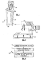
- Figure 1 illustrates an example part 20 that is formed from a metallic alloy material.
- the alloy may be any type of alloy desired for use in the part 20, such as a nickel alloy or cobalt alloy.
- the part 20 is an airfoil turbine blade for use in a gas turbine engine.
- the part 20 includes an airfoil section 22 that is connected to a root section 24 for mounting the part 20 in a gas turbine engine.
- the airfoil section 22 may include an internal cavity 26 for receiving a cooling fluid in a known manner, such as bleed air from a compressor section of a gas turbine engine, to facilitate cooling the part 20 during use.
- the part 20 is a finished part and may be ready for assembly into a gas turbine engine. In this regard, the part 20 may be new or used.
- the part 20 includes a protective coating 28 at least on the outer surface of the airfoil section 22 to protect the underlying alloy from erosion, corrosion, or the like during operation.
- the protective coating 28 may include an aluminide coating, an MCrAlY coating, or other type of protective coating.
- the M includes at least one of nickel, cobalt, iron, or a combination thereof, Cr is chromium, A1 is aluminum, and Y is yttrium or other active element.
- the part 20 may undergo various operations during original manufacture, repair, or other stage in the life cycle of the part 20.
- an operation might require rigidly mounting/holding the part 20.
- the part 20 may be mounted in a block 40, which facilitates rigidly holding the part 20 for conducting the operation.
- the operation may include machining the root section 24 of the part 20.
- the block 40 may be attached to another piece 42 to facilitate holding the part 20.
- the block 40 may be formed from a low melting alloy (LMA), that is an alloy with a low melting temperature, relative to the alloy of the part 20.
- LMA low melting alloy
- the LMA may be a bismuth-tin alloy.
- the mounting block 40 is removed by heating and melting the LMA.
- the part 20 may then be rinsed in a cleaning solution, such as a suitable acidic solution that reacts with the LMA but does not harm the alloy, to remove any residual LMA.
- the removal process normally removes all of the LMA from the part 20.
- trace amounts of the LMA may remain on the part 20 and diffuse into the alloy in elemental form or to form compounds with elements of the alloy, e.g., during subsequent thermal treatment.
- the part 20 is typically subjected to thermal treatment during or after application of the protective coating 28 or after a machining operation, for example.
- a premise of this disclosure is that the tin or the LMA may diffuse into the part 20 in elemental form or alloy to form undesired tin compounds, each of which may be difficult to detect in small amounts.
- the estimated total amount of the tin that may diffuse into the part 20 is only about 0.1 milligrams, if even present at all.
- the tin forms compounds, the tin is difficult to remove from the part 20 or detect without destroying the part.
- known inspection techniques such as atomic absorption, that may typically be used to detect such elements/compounds are not suitable for detection.
- Figure 3 illustrates an example non-destructive inspection method 50 for detecting the presence of a contaminant element, such as tin, that has alloyed with the metallic alloy of the part 20.
- a contaminant element such as tin
- “non-destructive” may refer to evaluation of the part 20 without causing harm such that the part 20 can be used for its intended function, i.e., without a change in the performance due to the inspection.
- the method 50 generally includes three steps, an exposure step 52, an extraction step 54, and an analysis step 56.
- the metallic alloy of the part 20 is a nickel alloy.
- the exposure step 52 may include exposing the nickel alloy of the part 20 to an extraction solution. Some or all of the surfaces of the part 20 may be exposed to the extraction solution, depending on the type of the part 20.
- the extraction solution and exposure conditions may be controlled such that the solution does not chemically attack the alloy of the part 20, as will be described below.
- the extraction solution leaches the contaminant element, if present, out from the alloy in the extraction step 54.
- the contaminant element may be in elemental form dissolved in the solution or in the compound form.
- the extraction solution can then be analyzed to determine whether the solution includes any of the contaminant element. The presence of the contaminant in the extraction solution indicates that the part 20 includes the contaminant element.
- the extraction solution may be a hydrochloric acid solution.
- the acid concentration of the hydrochloric acid solution and exposure time may be controlled to avoid chemical attack on the nickel alloy of the airfoil.
- the acid concentration may be 50% and the exposure time may be less than about two hours. In a further example, the exposure time may be about 30 minutes. Exposure times of more than two hours may result in chemical attack that oxidizes the alloy and materially changes the properties.
- the airfoil may be masked to shield the protective coating 28 from exposure to the hydrochloric acid solution.
- any openings on the outer surface of the part connecting to the internal cavity 26 in the airfoil section 22 may be covered, e.g., using a suitable tape or other masking agent.
- all or a portion of the airfoil section 22 may be sealed within a plastic cover or the like such that only the root section 24, which does not include the protective coating 28, is exposed.
- the masking, plastic cover and sealing may depend on the design of the remainder of the part and access to the internal cavity 26.
- the hydrochloric acid solution is injected into the internal cavity 26 to expose the nickel alloy of the airfoil to the solution. That is, the outside of the airfoil cannot be exposed to the hydrochloric acid solution because the solution may chemically attack the protective coating 28.
- the surfaces of the internal cavity 26 generally do not include the protective coating 28 and are therefore suitable for exposure to the solution, which does not readily react with the nickel alloy in the given concentration and exposure time.
- portions of the internal cavity 26 may include the protective coating 28, but the coating is not required and removal via the hydrochloric acid solution is acceptable.
- the shape of the internal cavity 26 may vary, e.g., depending on the design of the part.
- the internal cavity 26 may be a completely open cavity.
- the internal cavity 26 may be a serpentine passage extending between the root section 24 and the tip of the airfoil section 22.
- all of the surfaces of the internal cavity 26 can be exposed to the hydrochloric acid solution to facilitate extracting any of the tin contaminant.
- the hydrochloric acid solution may be injected with force into the internal cavity 26.
- a syringe may be used to manually or automatically inject the hydrochloric acid solution.
- a tube such as a polytetrafluoroethylene tube, may be connected to an orifice in the tip of the airfoil section 22 to inject the hydrochloric acid solution.
- the injection force causes the solution to flow throughout the internal cavity 26. In some cases, the force may facilitate flow of the solution through the serpentine passage where gravity alone would be inadequate.
- the hydrochloric acid solution remains in the internal cavity 26 for the selected exposure time. After the exposure time, the hydrochloric acid solution is drained from the internal cavity 26 into a beaker or other suitable container. The masking and plastic bag may then be removed and the airfoil may be washed to remove any residual hydrochloric acid solution from the internal cavity 26.
- the hydrochloric acid solution reacts with any of the tin contaminant or tin compounds near the surfaces of the internal cavity 26 to extract the tin contaminant from the nickel alloy into the hydrochloric acid solution.
- the relative amount of tin in the airfoil is small such that there may be ultra low levels of the tin contaminant at the surfaces of the internal cavity 26.
- the concentration of the tin contaminant extracted into the hydrochloric acid solution may be only a few hundredths of one part per million, e.g., one to one-hundred parts per billion.
- the hydrochloric acid solution that has been exposed to the nickel alloy is then analyzed in the analysis step 56 to determine whether the solution contains any of the tin contaminant.
- an inductively coupled plasma (ICP) analyzer may be used to analyze the hydrochloric acid solution and determine whether the solution includes any tin contaminant.
- the ICP instrument may be adapted to provide a detection limit as low as 0.01 parts per million.
- ICP instruments generate a plasma such that elements within a sample emit characteristic, wavelength-specific light that can be measured to detect the elements.
- the solution Prior to subjecting the solution to the ICP analysis, the solution may be diluted to a lower concentration level to avoid harming the ICP equipment. In one example, the solution is diluted to a 15% acid concentration.
- Parameters of the ICP equipment may be adjusted to facilitate providing a desired detection limit.
- the nebulizer, power supply, gas flow, sample introduction tube, torch, and cyclonic chamber may be adjusted to provide the 0.01 ppm detection limit desired to analyze the hydrochloric acid solution.
- a user may analyze the hydrochloric acid solution using the following steps with the ICP equipment:
Landscapes
- Chemical & Material Sciences (AREA)
- Health & Medical Sciences (AREA)
- Life Sciences & Earth Sciences (AREA)
- Immunology (AREA)
- Biochemistry (AREA)
- Pathology (AREA)
- General Physics & Mathematics (AREA)
- General Health & Medical Sciences (AREA)
- Physics & Mathematics (AREA)
- Engineering & Computer Science (AREA)
- Analytical Chemistry (AREA)
- General Chemical & Material Sciences (AREA)
- Materials Engineering (AREA)
- Organic Chemistry (AREA)
- Metallurgy (AREA)
- Chemical Kinetics & Catalysis (AREA)
- Mechanical Engineering (AREA)
- Food Science & Technology (AREA)
- Medicinal Chemistry (AREA)
- Investigating And Analyzing Materials By Characteristic Methods (AREA)
- Turbine Rotor Nozzle Sealing (AREA)
Claims (13)
- Zerstörungsfreies Prüfverfahren zum Feststellen der Anwesenheit einer Verunreinigung, die mit metallischer Legierung eines Strömungsprofils (20) eine Legierung gebildet hat, aufweisend:(a) Exponieren der metallischen Legierung des Strömungsprofils (20) einer Extraktionslösung, wobei das Exponieren ein Einspritzen der Extraktionslösung in einen Innenhohlraum (26) des Strömungsprofils (20) und ein Abdecken von Bereichen des Strömungsprofils, die eine Schutzbeschichtung (28) auf der metallischen Legierung aufweisen, umfasst;(b) Extrahieren mindestens eines Teils von Irgendetwas von der Verunreinigung, die mit der metallischen Legierung eine Legierung gebildet hat, in die Extraktionslösung; und(c) Bestimmen, ob die Extraktionslösung, die der metallischen Legierung exponiert wurde, Etwas von der Verunreinigung enthält.
- Zerstörungsfreies Prüfverfahren wie in Anspruch 1 angegeben, bei dem Schritt (a) ein Exponieren der metallischen Legierung der Extraktionslösung für eine Zeit, die geeignet ist, einen chemischen Angriff der Extraktionslösung auf die metallische Legierung zu vermeiden, umfasst.
- Zerstörungsfreies Prüfverfahren wie in einem vorangehenden Anspruch angegeben, bei dem Schritt (a) ein Wählen der Extraktionslösung dergestalt, dass sie Chlorwasserstoffsäure aufweist, umfasst.
- Zerstörungsfreies Prüfverfahren wie in einem vorangehenden Anspruch angegeben, bei dem Schritt (c) ein Unterziehen der Extraktionslösung, die der metallischen Legierung exponiert wurde, einer Analyse mit induktiv gekoppeltem Plasma (ICP) umfasst, um zu bestimmen, ob die Extraktionslösung Etwas von der Verunreinigung enthält.
- Zerstörungsfreies Prüfverfahren wie in einem vorangehenden Anspruch angegeben, bei dem die Verunreinigung Zinn umfasst und die metallische Legierung ausgewählt wird aus einer Gruppe, die aus einer Nickellegierung und einer Kobaltlegierung besteht, und das Zinn mit mindestens einem Element der metallischen Legierung eine Legierung bildet.
- Zerstörungsfreies Prüfverfahren nach Anspruch 1 zum Feststellen der Anwesenheit einer Zinn-Verunreinigung, die mit einer Nickellegierung des Strömungsprofils (20) eine Legierung gebildet hat, bei dem Schritt (a) ein Einspritzen einer Chlorwasserstoffsäure-Lösung in den Innenhohlraum (26) des Strömungsprofils (20) umfasst, um den Innenhohlraum (26) der Chlorwasserstoffsäure-Lösung für eine Zeit zu exponieren, die geeignet ist, um einen chemischen Angriff der Chlorwasserstoffsäure-Lösung auf die Nickellegierung zu vermeiden; Schritt (b) ein Extrahieren mindestens eines Teils jeglicher Zinn-Verunreinigung, die mit der Nickellegierung eine Legierung gebildet hat, in die Chlorwasserstoffsäure-Lösung umfasst; und Schritt (c) ein Unterziehen der Chlorwasserstoffsäure-Lösung, die der Nickellegierung exponiert wurde, einer Analyse mit induktiv gekoppeltem Plasma (ICP) umfasst, um zu bestimmen, ob die Chlorwasserstoffsäure-Lösung Etwas von der Zinn-Verunreinigung enthält, um dadurch zu bestimmen, ob das Strömungsprofil (20) die Zinn-Verunreinigung enthält.
- Zerstörungsfreies Prüfverfahren wie in Anspruch 6 angegeben, bei dem die Chlorwasserstoffsäure-Lösung eine 50%-ige Säurekonzentration hat.
- Zerstörungsfreies Prüfverfahren wie in Anspruch 6 oder 7 angegeben, bei dem Schritt (a) ein Einspritzen der Chlorwasserstoffsäure-Lösung unter Verwendung einer Spritze umfasst, um die Chlorwasserstoffsäure-Lösung in den Innenhohlraum des Strömungsprofils (20) zu drängen.
- Zerstörungsfreies Prüfverfahren wie in Anspruch 6, 7 oder 8 angegeben, bei dem Schritt (a) ein Abdecken eines äußeren Bereichs des Strömungsprofils (20) umfasst, um eine Schutzbeschichtung (28) an der Außenseite von der Chlorwasserstoffsäure-Lösung abzuschirmen.
- Zerstörungsfreies Prüfverfahren wie in einem der Ansprüche 6 bis 9 angegeben, bei dem Schritt (a) ein Exponieren der Chlorwasserstoffsäure-Lösung für eine Zeit, die geringer als zwei Stunden ist, umfasst.
- Zerstörungsfreies Prüfverfahren wie in einem der Ansprüche 6 bis 10 angegeben, außerdem umfassend ein Waschen des Strömungsprofils (20) nach Schritt (b), um etwaige restliche Chlorwasserstoffsäure-Lösung in dem Innenhohlraum (26) zu entfernen.
- Zerstörungsfreies Prüfverfahren wie in einem der Ansprüche 6 bis 11 angegeben, außerdem umfassend ein Verdünnen der Chlorwasserstoffsäure-Lösung vor Schritt (c) bei der Vorbereitung des Unterziehens der Chlorwasserstoffsäure-Lösung der ICP-Analyse.
- Zerstörungsfreies Prüfverfahren wie in einem der Ansprüche 6 bis 12 angegeben, außerdem umfassend, vor Schritt (a), ein Befestigen des Strömungsprofils (20) in einem Befestigungsblock (40), der eine niedrigschmelzende Legierung mit Zinn aufweist, und danach, nach dem Entfernen des Befestigungsblocks (40), ein Durchführen einer Wärmebehandlung des Strömungsprofils (20) dergestalt, dass etwaiges restliches Zinn mit der Nickellegierung eine Legierung bildet.
Applications Claiming Priority (1)
| Application Number | Priority Date | Filing Date | Title |
|---|---|---|---|
| US12/535,896 US8616077B2 (en) | 2009-08-05 | 2009-08-05 | Non-destructive inspection method for metallic alloys |
Publications (2)
| Publication Number | Publication Date |
|---|---|
| EP2284532A1 EP2284532A1 (de) | 2011-02-16 |
| EP2284532B1 true EP2284532B1 (de) | 2012-06-20 |
Family
ID=43066937
Family Applications (1)
| Application Number | Title | Priority Date | Filing Date |
|---|---|---|---|
| EP10251264A Not-in-force EP2284532B1 (de) | 2009-08-05 | 2010-07-14 | Nichtdestruktives Prüfverfahren für metallische Legierungen |
Country Status (2)
| Country | Link |
|---|---|
| US (1) | US8616077B2 (de) |
| EP (1) | EP2284532B1 (de) |
Family Cites Families (15)
| Publication number | Priority date | Publication date | Assignee | Title |
|---|---|---|---|---|
| US3701631A (en) | 1971-04-21 | 1972-10-31 | Nasa | Nondestructive spot test method for titanium and titanium alloys |
| US4886552A (en) | 1988-09-09 | 1989-12-12 | United Technologies Corporation | Method for monitoring the removal of a metallic contaminant from the surface of a metallic article |
| JP3215487B2 (ja) | 1992-04-13 | 2001-10-09 | セイコーインスツルメンツ株式会社 | 誘導結合プラズマ質量分析装置 |
| DE19642732A1 (de) * | 1995-10-16 | 1997-04-17 | Siemens Ag | Verfahren zur Entfernung von Zinn |
| EP0770709B1 (de) * | 1995-10-25 | 2000-04-12 | Tosoh Corporation | Kathode mit niedriger Wasserstoffüberspannung und deren Herstellungsverfahren |
| US5851303A (en) | 1996-05-02 | 1998-12-22 | Hemlock Semiconductor Corporation | Method for removing metal surface contaminants from silicon |
| US5882378A (en) | 1997-07-25 | 1999-03-16 | L'air Liquide Societe Anonyme Pour L'etude Et L'exploitation Des Procedes Georges Claude | Method to detect metal impurities in the semiconductor process gases |
| US6068541A (en) | 1997-12-22 | 2000-05-30 | United Technologies Corporation | Method for using a fixture enabling more accurate machining of a part |
| JPH11326280A (ja) | 1998-05-20 | 1999-11-26 | Shin Etsu Handotai Co Ltd | 微量金属の分析方法 |
| US6176999B1 (en) | 1998-12-18 | 2001-01-23 | United Technologies Corporation | Feedback controlled stripping of airfoils |
| US6627833B2 (en) | 2002-01-30 | 2003-09-30 | United Technologies Corporation | Fixture for securing a workpiece |
| US20040232584A1 (en) | 2003-05-20 | 2004-11-25 | Johnson David William | Testing of fabricated fluoropolymer articles for metal contamination |
| US20070292991A1 (en) | 2006-06-20 | 2007-12-20 | Lisa Edith Helberg | Method for quantification of analytes in a titanium, tin or silcon tetrachloride sample |
| US7563384B2 (en) | 2006-07-28 | 2009-07-21 | Honeywell International Inc. | Essentially non-flammable low global warming compositions |
| JP4773399B2 (ja) * | 2007-05-18 | 2011-09-14 | 矢崎総業株式会社 | スズまたはスズ合金めっき層の定量分析方法 |
-
2009
- 2009-08-05 US US12/535,896 patent/US8616077B2/en not_active Expired - Fee Related
-
2010
- 2010-07-14 EP EP10251264A patent/EP2284532B1/de not_active Not-in-force
Also Published As
| Publication number | Publication date |
|---|---|
| US8616077B2 (en) | 2013-12-31 |
| US20110030456A1 (en) | 2011-02-10 |
| EP2284532A1 (de) | 2011-02-16 |
Similar Documents
| Publication | Publication Date | Title |
|---|---|---|
| CN104764685B (zh) | 一种薄壁内覆耐蚀合金复合管的晶间腐蚀试验方法 | |
| CN102364331B (zh) | 一种奥氏体不锈钢表面铁污染分级的方法 | |
| US7010987B2 (en) | Non-destructive method of detecting defects in braze-repaired cracks | |
| GB2575365A (en) | Process | |
| EP2284532B1 (de) | Nichtdestruktives Prüfverfahren für metallische Legierungen | |
| US4886552A (en) | Method for monitoring the removal of a metallic contaminant from the surface of a metallic article | |
| US6793738B2 (en) | Method for processing acid treatment solution, solution processed thereby, and method for treating articles therewith | |
| CN105521973B (zh) | 激光器冷却箱的洁净方法及其洁净度的检测方法 | |
| US20090065023A1 (en) | Microwave assisted post-FPI cleaning method | |
| KR20180007251A (ko) | 지르코늄 합금 튜브의 고효율 세정을 위한 진공초음파 세정기술 | |
| EP2492667B1 (de) | Verfahren zur Erkennung von Zinn | |
| JPH04228259A (ja) | 微小縮みの同定・評価・除去方法 | |
| CN114323841A (zh) | 一种等轴晶高温合金铸件荧光检测前化学预处理方法 | |
| CN109507191B (zh) | 一种粉末冶金材料表面冶金缺陷的腐蚀检测方法 | |
| KR100919226B1 (ko) | 금속 도금층 두께 평가를 위한 전기화학적 방법 | |
| EP1416269A1 (de) | Zerstörungsfreies Verfahren zum Erkennen von Defekten in durch Löten reparierten Rissen | |
| CN106680178A (zh) | 一种银镁镍材料上镀金层孔隙检测方法 | |
| EP3266902B1 (de) | Oxidfilmentfernungsverfahren | |
| CN116879336A (zh) | 一种铜及铜合金管内表面残碳的测试方法 | |
| CN121347354A (zh) | 一种航空发动机整机的腐蚀损伤分析方法 | |
| Kim et al. | Airborne emissions and corrosion of stainless bellows under simulated semiconductor halide environment | |
| Glazkov | Engineering features of preparing parts for inspection via penetrant luminescence methods | |
| CN115015011A (zh) | 一种汽轮机高压调节级叶片沟槽裂纹形成的分析方法 | |
| IES980638A2 (en) | Method of cleaning metal components | |
| Sturm et al. | Online multielement analysis of the top gas of a blast furnace by laser-induced breakdown spectroscopy (LIBS) |
Legal Events
| Date | Code | Title | Description |
|---|---|---|---|
| PUAI | Public reference made under article 153(3) epc to a published international application that has entered the european phase |
Free format text: ORIGINAL CODE: 0009012 |
|
| AK | Designated contracting states |
Kind code of ref document: A1 Designated state(s): AL AT BE BG CH CY CZ DE DK EE ES FI FR GB GR HR HU IE IS IT LI LT LU LV MC MK MT NL NO PL PT RO SE SI SK SM TR |
|
| AX | Request for extension of the european patent |
Extension state: BA ME RS |
|
| GRAJ | Information related to disapproval of communication of intention to grant by the applicant or resumption of examination proceedings by the epo deleted |
Free format text: ORIGINAL CODE: EPIDOSDIGR1 |
|
| GRAP | Despatch of communication of intention to grant a patent |
Free format text: ORIGINAL CODE: EPIDOSNIGR1 |
|
| 17P | Request for examination filed |
Effective date: 20110816 |
|
| RIC1 | Information provided on ipc code assigned before grant |
Ipc: C23F 1/30 20060101ALI20110912BHEP Ipc: G01N 33/20 20060101AFI20110912BHEP Ipc: G01N 1/40 20060101ALI20110912BHEP |
|
| GRAP | Despatch of communication of intention to grant a patent |
Free format text: ORIGINAL CODE: EPIDOSNIGR1 |
|
| GRAS | Grant fee paid |
Free format text: ORIGINAL CODE: EPIDOSNIGR3 |
|
| GRAA | (expected) grant |
Free format text: ORIGINAL CODE: 0009210 |
|
| AK | Designated contracting states |
Kind code of ref document: B1 Designated state(s): AL AT BE BG CH CY CZ DE DK EE ES FI FR GB GR HR HU IE IS IT LI LT LU LV MC MK MT NL NO PL PT RO SE SI SK SM TR |
|
| REG | Reference to a national code |
Ref country code: GB Ref legal event code: FG4D |
|
| REG | Reference to a national code |
Ref country code: CH Ref legal event code: EP |
|
| REG | Reference to a national code |
Ref country code: AT Ref legal event code: REF Ref document number: 563333 Country of ref document: AT Kind code of ref document: T Effective date: 20120715 |
|
| REG | Reference to a national code |
Ref country code: IE Ref legal event code: FG4D |
|
| REG | Reference to a national code |
Ref country code: DE Ref legal event code: R096 Ref document number: 602010001968 Country of ref document: DE Effective date: 20120816 |
|
| PG25 | Lapsed in a contracting state [announced via postgrant information from national office to epo] |
Ref country code: LT Free format text: LAPSE BECAUSE OF FAILURE TO SUBMIT A TRANSLATION OF THE DESCRIPTION OR TO PAY THE FEE WITHIN THE PRESCRIBED TIME-LIMIT Effective date: 20120620 Ref country code: FI Free format text: LAPSE BECAUSE OF FAILURE TO SUBMIT A TRANSLATION OF THE DESCRIPTION OR TO PAY THE FEE WITHIN THE PRESCRIBED TIME-LIMIT Effective date: 20120620 Ref country code: NO Free format text: LAPSE BECAUSE OF FAILURE TO SUBMIT A TRANSLATION OF THE DESCRIPTION OR TO PAY THE FEE WITHIN THE PRESCRIBED TIME-LIMIT Effective date: 20120920 Ref country code: SE Free format text: LAPSE BECAUSE OF FAILURE TO SUBMIT A TRANSLATION OF THE DESCRIPTION OR TO PAY THE FEE WITHIN THE PRESCRIBED TIME-LIMIT Effective date: 20120620 |
|
| REG | Reference to a national code |
Ref country code: NL Ref legal event code: VDEP Effective date: 20120620 |
|
| REG | Reference to a national code |
Ref country code: AT Ref legal event code: MK05 Ref document number: 563333 Country of ref document: AT Kind code of ref document: T Effective date: 20120620 |
|
| REG | Reference to a national code |
Ref country code: LT Ref legal event code: MG4D Effective date: 20120620 |
|
| PG25 | Lapsed in a contracting state [announced via postgrant information from national office to epo] |
Ref country code: GR Free format text: LAPSE BECAUSE OF FAILURE TO SUBMIT A TRANSLATION OF THE DESCRIPTION OR TO PAY THE FEE WITHIN THE PRESCRIBED TIME-LIMIT Effective date: 20120921 Ref country code: LV Free format text: LAPSE BECAUSE OF FAILURE TO SUBMIT A TRANSLATION OF THE DESCRIPTION OR TO PAY THE FEE WITHIN THE PRESCRIBED TIME-LIMIT Effective date: 20120620 Ref country code: SI Free format text: LAPSE BECAUSE OF FAILURE TO SUBMIT A TRANSLATION OF THE DESCRIPTION OR TO PAY THE FEE WITHIN THE PRESCRIBED TIME-LIMIT Effective date: 20120620 Ref country code: HR Free format text: LAPSE BECAUSE OF FAILURE TO SUBMIT A TRANSLATION OF THE DESCRIPTION OR TO PAY THE FEE WITHIN THE PRESCRIBED TIME-LIMIT Effective date: 20120620 |
|
| PGFP | Annual fee paid to national office [announced via postgrant information from national office to epo] |
Ref country code: DE Payment date: 20120711 Year of fee payment: 3 |
|
| PG25 | Lapsed in a contracting state [announced via postgrant information from national office to epo] |
Ref country code: RO Free format text: LAPSE BECAUSE OF FAILURE TO SUBMIT A TRANSLATION OF THE DESCRIPTION OR TO PAY THE FEE WITHIN THE PRESCRIBED TIME-LIMIT Effective date: 20120620 Ref country code: CY Free format text: LAPSE BECAUSE OF FAILURE TO SUBMIT A TRANSLATION OF THE DESCRIPTION OR TO PAY THE FEE WITHIN THE PRESCRIBED TIME-LIMIT Effective date: 20120620 Ref country code: BE Free format text: LAPSE BECAUSE OF FAILURE TO SUBMIT A TRANSLATION OF THE DESCRIPTION OR TO PAY THE FEE WITHIN THE PRESCRIBED TIME-LIMIT Effective date: 20120620 Ref country code: IS Free format text: LAPSE BECAUSE OF FAILURE TO SUBMIT A TRANSLATION OF THE DESCRIPTION OR TO PAY THE FEE WITHIN THE PRESCRIBED TIME-LIMIT Effective date: 20121020 Ref country code: SK Free format text: LAPSE BECAUSE OF FAILURE TO SUBMIT A TRANSLATION OF THE DESCRIPTION OR TO PAY THE FEE WITHIN THE PRESCRIBED TIME-LIMIT Effective date: 20120620 Ref country code: CZ Free format text: LAPSE BECAUSE OF FAILURE TO SUBMIT A TRANSLATION OF THE DESCRIPTION OR TO PAY THE FEE WITHIN THE PRESCRIBED TIME-LIMIT Effective date: 20120620 Ref country code: EE Free format text: LAPSE BECAUSE OF FAILURE TO SUBMIT A TRANSLATION OF THE DESCRIPTION OR TO PAY THE FEE WITHIN THE PRESCRIBED TIME-LIMIT Effective date: 20120620 Ref country code: AT Free format text: LAPSE BECAUSE OF FAILURE TO SUBMIT A TRANSLATION OF THE DESCRIPTION OR TO PAY THE FEE WITHIN THE PRESCRIBED TIME-LIMIT Effective date: 20120620 |
|
| PG25 | Lapsed in a contracting state [announced via postgrant information from national office to epo] |
Ref country code: MK Free format text: LAPSE BECAUSE OF FAILURE TO SUBMIT A TRANSLATION OF THE DESCRIPTION OR TO PAY THE FEE WITHIN THE PRESCRIBED TIME-LIMIT Effective date: 20120620 Ref country code: PL Free format text: LAPSE BECAUSE OF FAILURE TO SUBMIT A TRANSLATION OF THE DESCRIPTION OR TO PAY THE FEE WITHIN THE PRESCRIBED TIME-LIMIT Effective date: 20120620 Ref country code: PT Free format text: LAPSE BECAUSE OF FAILURE TO SUBMIT A TRANSLATION OF THE DESCRIPTION OR TO PAY THE FEE WITHIN THE PRESCRIBED TIME-LIMIT Effective date: 20121022 Ref country code: IT Free format text: LAPSE BECAUSE OF FAILURE TO SUBMIT A TRANSLATION OF THE DESCRIPTION OR TO PAY THE FEE WITHIN THE PRESCRIBED TIME-LIMIT Effective date: 20120620 Ref country code: MC Free format text: LAPSE BECAUSE OF NON-PAYMENT OF DUE FEES Effective date: 20120731 |
|
| PG25 | Lapsed in a contracting state [announced via postgrant information from national office to epo] |
Ref country code: NL Free format text: LAPSE BECAUSE OF FAILURE TO SUBMIT A TRANSLATION OF THE DESCRIPTION OR TO PAY THE FEE WITHIN THE PRESCRIBED TIME-LIMIT Effective date: 20120620 |
|
| PLBE | No opposition filed within time limit |
Free format text: ORIGINAL CODE: 0009261 |
|
| REG | Reference to a national code |
Ref country code: FR Ref legal event code: ST Effective date: 20130329 |
|
| STAA | Information on the status of an ep patent application or granted ep patent |
Free format text: STATUS: NO OPPOSITION FILED WITHIN TIME LIMIT |
|
| PG25 | Lapsed in a contracting state [announced via postgrant information from national office to epo] |
Ref country code: FR Free format text: LAPSE BECAUSE OF NON-PAYMENT OF DUE FEES Effective date: 20120820 Ref country code: DK Free format text: LAPSE BECAUSE OF FAILURE TO SUBMIT A TRANSLATION OF THE DESCRIPTION OR TO PAY THE FEE WITHIN THE PRESCRIBED TIME-LIMIT Effective date: 20120620 Ref country code: ES Free format text: LAPSE BECAUSE OF FAILURE TO SUBMIT A TRANSLATION OF THE DESCRIPTION OR TO PAY THE FEE WITHIN THE PRESCRIBED TIME-LIMIT Effective date: 20121001 |
|
| REG | Reference to a national code |
Ref country code: IE Ref legal event code: MM4A |
|
| 26N | No opposition filed |
Effective date: 20130321 |
|
| REG | Reference to a national code |
Ref country code: DE Ref legal event code: R097 Ref document number: 602010001968 Country of ref document: DE Effective date: 20130321 |
|
| PG25 | Lapsed in a contracting state [announced via postgrant information from national office to epo] |
Ref country code: MT Free format text: LAPSE BECAUSE OF FAILURE TO SUBMIT A TRANSLATION OF THE DESCRIPTION OR TO PAY THE FEE WITHIN THE PRESCRIBED TIME-LIMIT Effective date: 20120620 Ref country code: IE Free format text: LAPSE BECAUSE OF NON-PAYMENT OF DUE FEES Effective date: 20120714 Ref country code: BG Free format text: LAPSE BECAUSE OF FAILURE TO SUBMIT A TRANSLATION OF THE DESCRIPTION OR TO PAY THE FEE WITHIN THE PRESCRIBED TIME-LIMIT Effective date: 20120920 |
|
| PG25 | Lapsed in a contracting state [announced via postgrant information from national office to epo] |
Ref country code: AL Free format text: LAPSE BECAUSE OF FAILURE TO SUBMIT A TRANSLATION OF THE DESCRIPTION OR TO PAY THE FEE WITHIN THE PRESCRIBED TIME-LIMIT Effective date: 20120620 |
|
| REG | Reference to a national code |
Ref country code: DE Ref legal event code: R119 Ref document number: 602010001968 Country of ref document: DE Effective date: 20140201 |
|
| PG25 | Lapsed in a contracting state [announced via postgrant information from national office to epo] |
Ref country code: DE Free format text: LAPSE BECAUSE OF NON-PAYMENT OF DUE FEES Effective date: 20140201 Ref country code: TR Free format text: LAPSE BECAUSE OF FAILURE TO SUBMIT A TRANSLATION OF THE DESCRIPTION OR TO PAY THE FEE WITHIN THE PRESCRIBED TIME-LIMIT Effective date: 20120620 |
|
| PG25 | Lapsed in a contracting state [announced via postgrant information from national office to epo] |
Ref country code: SM Free format text: LAPSE BECAUSE OF FAILURE TO SUBMIT A TRANSLATION OF THE DESCRIPTION OR TO PAY THE FEE WITHIN THE PRESCRIBED TIME-LIMIT Effective date: 20120620 Ref country code: LU Free format text: LAPSE BECAUSE OF NON-PAYMENT OF DUE FEES Effective date: 20120714 |
|
| PG25 | Lapsed in a contracting state [announced via postgrant information from national office to epo] |
Ref country code: HU Free format text: LAPSE BECAUSE OF FAILURE TO SUBMIT A TRANSLATION OF THE DESCRIPTION OR TO PAY THE FEE WITHIN THE PRESCRIBED TIME-LIMIT Effective date: 20100714 |
|
| REG | Reference to a national code |
Ref country code: CH Ref legal event code: PL |
|
| PG25 | Lapsed in a contracting state [announced via postgrant information from national office to epo] |
Ref country code: CH Free format text: LAPSE BECAUSE OF NON-PAYMENT OF DUE FEES Effective date: 20140731 Ref country code: LI Free format text: LAPSE BECAUSE OF NON-PAYMENT OF DUE FEES Effective date: 20140731 |
|
| PGFP | Annual fee paid to national office [announced via postgrant information from national office to epo] |
Ref country code: GB Payment date: 20230620 Year of fee payment: 14 |
|
| GBPC | Gb: european patent ceased through non-payment of renewal fee |
Effective date: 20240714 |
|
| PG25 | Lapsed in a contracting state [announced via postgrant information from national office to epo] |
Ref country code: GB Free format text: LAPSE BECAUSE OF NON-PAYMENT OF DUE FEES Effective date: 20240714 |