EP2284460B1 - Refrigeration apparatus - Google Patents
Refrigeration apparatus Download PDFInfo
- Publication number
- EP2284460B1 EP2284460B1 EP10172556.2A EP10172556A EP2284460B1 EP 2284460 B1 EP2284460 B1 EP 2284460B1 EP 10172556 A EP10172556 A EP 10172556A EP 2284460 B1 EP2284460 B1 EP 2284460B1
- Authority
- EP
- European Patent Office
- Prior art keywords
- refrigeration
- condenser
- refrigerant
- heat exchanger
- refrigeration apparatus
- Prior art date
- Legal status (The legal status is an assumption and is not a legal conclusion. Google has not performed a legal analysis and makes no representation as to the accuracy of the status listed.)
- Active
Links
Images



Classifications
-
- F—MECHANICAL ENGINEERING; LIGHTING; HEATING; WEAPONS; BLASTING
- F25—REFRIGERATION OR COOLING; COMBINED HEATING AND REFRIGERATION SYSTEMS; HEAT PUMP SYSTEMS; MANUFACTURE OR STORAGE OF ICE; LIQUEFACTION SOLIDIFICATION OF GASES
- F25B—REFRIGERATION MACHINES, PLANTS OR SYSTEMS; COMBINED HEATING AND REFRIGERATION SYSTEMS; HEAT PUMP SYSTEMS
- F25B39/00—Evaporators; Condensers
- F25B39/04—Condensers
-
- F—MECHANICAL ENGINEERING; LIGHTING; HEATING; WEAPONS; BLASTING
- F25—REFRIGERATION OR COOLING; COMBINED HEATING AND REFRIGERATION SYSTEMS; HEAT PUMP SYSTEMS; MANUFACTURE OR STORAGE OF ICE; LIQUEFACTION SOLIDIFICATION OF GASES
- F25C—PRODUCING, WORKING OR HANDLING ICE
- F25C1/00—Producing ice
- F25C1/12—Producing ice by freezing water on cooled surfaces, e.g. to form slabs
- F25C1/14—Producing ice by freezing water on cooled surfaces, e.g. to form slabs to form thin sheets which are removed by scraping or wedging, e.g. in the form of flakes
- F25C1/145—Producing ice by freezing water on cooled surfaces, e.g. to form slabs to form thin sheets which are removed by scraping or wedging, e.g. in the form of flakes from the inner walls of cooled bodies
- F25C1/147—Producing ice by freezing water on cooled surfaces, e.g. to form slabs to form thin sheets which are removed by scraping or wedging, e.g. in the form of flakes from the inner walls of cooled bodies by using augers
-
- F—MECHANICAL ENGINEERING; LIGHTING; HEATING; WEAPONS; BLASTING
- F25—REFRIGERATION OR COOLING; COMBINED HEATING AND REFRIGERATION SYSTEMS; HEAT PUMP SYSTEMS; MANUFACTURE OR STORAGE OF ICE; LIQUEFACTION SOLIDIFICATION OF GASES
- F25B—REFRIGERATION MACHINES, PLANTS OR SYSTEMS; COMBINED HEATING AND REFRIGERATION SYSTEMS; HEAT PUMP SYSTEMS
- F25B2400/00—Component parts or details not otherwise provided for in this subclass
- F25B2400/06—Several compression cycles arranged in parallel
-
- F—MECHANICAL ENGINEERING; LIGHTING; HEATING; WEAPONS; BLASTING
- F25—REFRIGERATION OR COOLING; COMBINED HEATING AND REFRIGERATION SYSTEMS; HEAT PUMP SYSTEMS; MANUFACTURE OR STORAGE OF ICE; LIQUEFACTION SOLIDIFICATION OF GASES
- F25B—REFRIGERATION MACHINES, PLANTS OR SYSTEMS; COMBINED HEATING AND REFRIGERATION SYSTEMS; HEAT PUMP SYSTEMS
- F25B2400/00—Component parts or details not otherwise provided for in this subclass
- F25B2400/12—Inflammable refrigerants
-
- F—MECHANICAL ENGINEERING; LIGHTING; HEATING; WEAPONS; BLASTING
- F25—REFRIGERATION OR COOLING; COMBINED HEATING AND REFRIGERATION SYSTEMS; HEAT PUMP SYSTEMS; MANUFACTURE OR STORAGE OF ICE; LIQUEFACTION SOLIDIFICATION OF GASES
- F25B—REFRIGERATION MACHINES, PLANTS OR SYSTEMS; COMBINED HEATING AND REFRIGERATION SYSTEMS; HEAT PUMP SYSTEMS
- F25B2500/00—Problems to be solved
- F25B2500/01—Geometry problems, e.g. for reducing size
Definitions
- the present invention relates to a refrigeration apparatus using a flammable refrigerant.
- Nonflammable chlorofluorocarbon refrigerants have been conventionally used as refrigerants of refrigeration apparatuses. However, since chlorofluorocarbon refrigerants have a harmful influence on the natural environment, alternative refrigerants have been sought for. Hydrocarbon (HC) refrigerants such as methane, ethane, propane, butane, pentane and the like are attracting our attention as alternative refrigerants replacing said chlorofluorocarbon refrigerants. However, since the HC refrigerants are flammable, a maximum filling amount (150 g) per one refrigeration circuit unit is regulated by law (for example, see Japanese Unexamined Patent Publication No. 2004-198062 ).
- the publication of the European Patent application EP 1 326 057 A 1 discloses a multi-type refrigerator which executes refrigerating cycles by circulating R32 as refrigerant through a refrigerant circuit including a compressor, a condenser, expansion means and evaporators.
- the volume of the condenser is set to be smaller than 0.75 liters.
- the filling amount of the refrigerant has a relatively small effect on refrigeration capacity.
- a condenser and the like were designed to take precedence over the downsizing of a machine, and no particular consideration was made for the filling amount of the refrigerant. Accordingly, if a construction similar to that of a refrigeration apparatus using a conventional chlorofluorocarbon refrigerant is adopted for a refrigeration apparatus using the above flammable refrigerant, the refrigerant may be filled more than the filling amount regulated by law. Furthermore, a desired refrigeration capacity may not be exhibited if the refrigerant is filled more than the legally regulated amount.
- the present invention was proposed to solve the problem, and an object thereof is to provide a refrigeration apparatus capable of ensuring a desired refrigeration capacity while observing a legal regulation on the filling amount of a flammable refrigerant.
- an aspect of the invention of the present application is directed to a refrigeration apparatus, having a refrigeration circuit comprising a compressor, a condenser, a decompression means and an evaporator each of which is connected by pipes and a flammable refrigerant is circulated therethrough, wherein volume per circuit in the refrigeration circuit is set equal to or smaller than 2200 ⁇ 10 -6 m 3 and volume of the condenser is set equal to or smaller than 750 ⁇ 10 -6 m 3 .
- a desired cooling capacity is ensured while a legal regulation on the filling amount of a flammable refrigerant is observed.
- an ice making machine 10 is provided with an ice making mechanism 12 for producing ice and a refrigeration apparatus 30 for refrigerating said ice-making mechanism 12.
- the ice-making mechanism 12 includes a cylindrical refrigeration casing 14, an auger 16 rotatably arranged inside of said refrigeration casing 14, a driving means (not shown) for rotating said auger 16 and an ice-making water tank 18 for supplying ice-making water to the refrigeration casing 14.
- An evaporator EP which will be described later constituting the refrigeration apparatus 30 is arranged on the outer circumference of the refrigeration casing 14.
- the interior of the refrigeration casing 14 is filled with the ice-making water supplied from the ice-making water tank 18 and this refrigeration casing 14 is cooled by the evaporator EP to cause ice to grow on an inner surface (ice-making surface) of the refrigeration casing 14.
- the auger 16 is rotated by the driving means to scrape off the ice grown on the ice-making surface, convey the scraped ice upward and discharge it to an ice storage chamber (not shown) via a guide 20 provided atop the refrigeration casing 14.
- the refrigeration apparatus 30 includes one so-called vapor compression type refrigeration circuit 34 (see Fig. 1 ) in which devices such as a compressor CM, a condenser CD to be cooled by a cooling fan FM, an expansion valve EV as a decompression means and a evaporator EP are connected by refrigerant pipes (piping) 32.
- a refrigerant is circulated in a pipe system of the refrigeration circuit 34 by driving the compressor CM and the cooling fan FM.
- the refrigerant decompressed by the expansion valve EV is allowed to flow into the evaporator EP, where the decompressed refrigerant is expanded and evaporated to cool the refrigeration casing 14 to below the freezing point.
- the vaporized refrigerant heat-exchanged with the refrigeration casing 14 by the evaporator EP returns to the compressor CM and is circulated in the refrigeration circuit 34 after being compressed again in the compressor CM.
- copper pipes are used as the refrigerant pipes 32.
- volume per circuit in the refrigeration circuit 34 is set equal to or smaller than 2200 ⁇ 10 -6 m 3 .
- a hydrocarbon (HC) refrigerant such as methane, ethane, propane, butane or pentane or ammonia or the like is employed. These refrigerants have good refrigerant characteristics such as heat of vaporization and saturation pressure.
- HC hydrocarbon
- isobutane or propane is used.
- the condenser CD is of the air-cooled type and disposed in a machine room (not shown) defined inside of the ice making machine 10.
- the condenser CD is arranged downstream of the compressor CM and upstream of the evaporator EV in the refrigeration circuit 34. Further, outside air taken into the machine room by the cooling fan FM comes into contact with the condenser CD, which then liquefies the high-temperature and highpressure vaporized refrigerant from the compressor CM by heat exchange with the outside air.
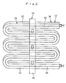
- the condenser CD includes a plurality of heat exchanger units 38, 38 (two units in the first embodiment) each composed of a tube 40 serving as a refrigerant path for permitting the flow of the refrigerant, and a fin 42 extending radially outward from the outer circumference of said tube 40.
- a so-called spiral fin tube in which the fin 42 is spirally wound around the outer circumference of the tube 40, is employed as each heat exchanger unit 38 of the first embodiment, and each heat exchanger unit 38 is formed to meander in such a manner that horizontally or substantially horizontally extending straight sections are placed one over another (see Fig. 2 ).
- the refrigerant pipe 32 at an upstream side is branched off into as many pipes as the heat exchanger units 38 in the condenser CD, the branched pipes are connected with the respective tubes 40, and the refrigerant pipes 32 connected with the downstream sides of the tubes 40 of the respective heat exchanger units 38 are joined so that one refrigerant tube 32 is connected with the expansion valve EV.
- the condenser CD includes two independent refrigerant paths for the respective heat exchanger units 38 and connected in parallel with the refrigeration circuit 34.
- the two systematic heat exchanger units 38, 38 are arranged in front and behind in an air flowing direction in the machine room (see Fig. 2 or 3 ).
- the condenser CD is so arranged that the straight sections of the respective heat exchanger units 38, 38 intersect with the flow of air caused by the cooling fan FM.
- the volume of the condenser CD is set equal to or smaller than 750 ⁇ 10 -6 m 3 .
- a total interior volume of the tubes 40 (refrigerant paths) in the two heat exchanger units 38, 38 is the volume of the condenser CD.
- Thin tubes made of metal having good thermal conductivity such as copper and having a diameter of 1.0 mm to 6.35 mm are employed as the tubes 40.
- the volume of the condenser CD of the first embodiment is reduced by 30 % or more.
- a fixing means 44 is so formed as to hold the adjacent two heat exchanger units 38, 3 8 as a pair and so arranged as to hold substantially central parts of the respective heat exchanger units 38, 38 in a lateral direction (extending direction of the straight sections) (see Fig. 2 ).
- the fixing means 44 is formed by combining a pair of supporting members 46, 46 arranged to face each other with the adjacent two heat exchanger units 38, 38 located therebetween and holding members 48 provided on the respective supporting members 46 for holding the corresponding heat exchanger units 38 (see Fig. 3 ).
- the fixing means 44 tightly holds the adjacent two heat exchanger units 38, 38 in contact by using the holding members 48, 48 respectively provided on the facing supporting members 46, 46.
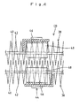
- the condenser CD may be such that fin 42 of the other heat exchanger unit 38 are inserted between corresponding fin 42 of one heat exchanger unit 38 to mesh the fins 42 of the both heat exchanger units 38, 38 with each other (see Fig. 4 ).
- the supporting member 46 is a long plate member whose longer sides extend in a vertical direction and are longer than a vertical dimension of the facing heat exchanger unit 38, so that the supporting member 46 is arranged to vertically extend over the heat exchanger unit 38.
- Each supporting member 46 is set to have a smaller width than the straight sections of the corresponding heat exchanger unit 38. Further, the respective supporting members 46 are separated in front and behind in the air flowing direction in the machine room and located at the central parts of the straight sections of the corresponding heat exchanger units 38.
- a temperature operation-type expansion valve having a temperature-sensitive tube TH is employed as the expansion valve EV.
- the temperature-sensitive tube TH is mounted on the refrigeration pipe 32 connected with the exit of the evaporator EP and is nearly positioned to the exit of the evaporator EP.
- the expansion valve EV is opened and closed according to the temperature of the vaporized refrigerant flowing in the refrigeration pipe 32 detected by the temperature-sensitive tube TH and efficiently operates by regulating the pressure of the evaporator EP.
- the evaporator EP is made of an evaporation pipe 50 spirally provided on the outer circumferential surface of the refrigeration casing 14.
- the refrigeration apparatus 30 of the first embodiment can suppress a filling amount of a flammable refrigerant required for one refrigeration circuit 34 to or below a specified value by (1) setting the volume per circuit in the refrigeration circuit 34 equal to or smaller than 2200 ⁇ 10 -6 m 3 and (2) setting the volume of the condenser CD equal to or smaller than 750 ⁇ 10 -6 m 3 .
- the refrigerant is present in a gaseous state or a liquid state in the refrigeration circuit 34 and a reduction in the volume of the refrigerant in the liquid state largely contributes to a reduction in the filling amount of the refrigerant.
- the compressor CM, the condenser CD and the evaporator EP can be cited as constituent devices with large volume ratios in the refrigeration circuit 34.
- the device that influences the filling amount of the refrigerant most out of the constituent devices is the condenser CD. Namely, the filling amount of the refrigerant in the refrigeration circuit 34 can be reduced more by suppressing the volume of the condenser CD to or below 750 ⁇ 10 -6 m 3 as in the refrigeration apparatus 30 of the first embodiment than by reducing the volume of the compressor CM or the evaporator EP. Since the condenser CD can be easily changed in shape as compared with the compressor CM having a driving mechanism and the evaporator EP needed to conform to the refrigeration casing 14, costs required for a volume change can be suppressed.
- the refrigeration apparatus 30 of the first embodiment can avoid the filling of the refrigerant more than the specified value into the refrigeration circuit 34 by setting the volumes of the refrigeration circuit 34 and the condenser CD as descried above.
- the refrigeration apparatus 30 can ensure a desired refrigeration capacity even if the volumes of the refrigeration circuit 34 and the condenser CD are reduced.
- the use of an HC refrigerant in a refrigeration apparatus having a refrigeration capacity of 300 W or lower is generally said to be possible.
- a refrigeration capacity equal to or higher than 300 W and equivalent to that of 650 W can be ensured per one refrigeration circuit 34 by setting the volumes of the refrigeration circuit 34 and the condenser CD as descried above.
- a refrigeration capacity equivalent to 1300 W can be obtained from one refrigeration circuit 34.
- the volume of the condenser CD is reduced by narrowing the tubes 40 constituting the refrigerant paths in the condenser CD.
- this condenser CD if the tubes 40 are set to be narrow, a pressure loss of the refrigerant paths increases and also a heat exchange area decreases, wherefore a condensation capacity decreases.
- the condenser CD of the first embodiment can ensure a heat exchange area without increasing lateral or vertical dimensions of the individual heat exchanger units 38, 38.
- the condenser CD can have a compact construction as a whole.
- the two heat exchanger units 38, 38 are connected in parallel with the refrigeration circuit 34 in the condenser CD of the first embodiment, lengths of the tubes 40 of the individual heat exchanger units 38, 38 can be shortened and the refrigerant in the refrigerant paths can be smoothly circulated by reducing the pressure loss.
- the volume of the condenser CD of the first embodiment is reduced by narrowing the tubes 40, a required condensation capacity can be ensured.
- the condenser CD is so constructed that parts of the straight sections of the heat exchanger units 38, 38 are held by the fixing means 44, areas of the heat exchanger units 38, 38 covered by the fixing means 44 can be made smaller as compared with the case where curved sections of the heat exchanger units are held. Namely, in the condenser CD, the flow of air through the heat exchanger units 38, 38 is not hindered by the fixing means 44 and the curved sections are also effectively utilized, wherefore heat exchange efficiency in the respective heat exchanger units 38, 38 can be improved.
- the fixing means 44 is for holding the heat exchanger units 38, 38 while vertically displacing one heat exchanger unit 38 and the other heat exchanger unit 38, air can be properly brought into contact with the straight sections of the other heat exchanger unit 38 exposed between the straight sections of the one heat exchanger unit 38 and heat exchange can be more efficiently performed.
- a refrigeration apparatus 60 of a second embodiment shown in Fig. 5 includes two refrigeration circuits 34, each of which is mutually independent.
- Each refrigeration circuit 34 of the second embodiment includes a compressor CM, a condenser CD, an expansion valve EV and an evaporator EP, each of which are connected by refrigerant pipes 32 and has a similar construction to the refrigeration circuit 34 of the first embodiment.
- the evaporators EP of the respective refrigeration circuits 34 are provided in a refrigeration casing 14
- two evaporators EP are provided on the outer circumference of the refrigeration casing 14.
- volume per circuit in each refrigeration circuit 34 of the second embodiment is set equal to or smaller than 2200 ⁇ 10 -6 m 3
- volume of the condenser CD is set equal to or smaller than 750 ⁇ 10 -6 m 3 .
- the two refrigeration circuits 34 are mutually independent in the refrigeration apparatus 60 of the second embodiment. Also, since the volume per circuit is set equal to or smaller than 2200 ⁇ 10 -6 m 3 and the volume of the condenser CD is set equal to or smaller than 750 ⁇ 10 -6 m 3 for each refrigeration circuit 34, the filling amount of the flammable refrigerant required for each refrigeration circuit 34 can be suppressed to or below a specified value. In addition, by providing the two refrigeration circuits 34, 34, the refrigeration apparatus 60 can increase its refrigeration capacity as a whole and cope with the large-size ice making machine 11.
- an operation of the refrigeration apparatus 60 can be changed to a refrigeration operation using the both refrigeration circuits 34, 34 and that using only one refrigeration circuit 34, so that the refrigerating capacity can be controlled in a stepwise manner. Therefore, if one refrigeration circuit 34 breaks down, the other refrigeration circuit 34 can be used as a backup means.
- the present invention is not limited to the constructions of the above embodiments and may be modified as follows.
Landscapes
- Engineering & Computer Science (AREA)
- Physics & Mathematics (AREA)
- Mechanical Engineering (AREA)
- Thermal Sciences (AREA)
- General Engineering & Computer Science (AREA)
- Devices That Are Associated With Refrigeration Equipment (AREA)
Description
- The present invention relates to a refrigeration apparatus using a flammable refrigerant.
- Nonflammable chlorofluorocarbon refrigerants have been conventionally used as refrigerants of refrigeration apparatuses. However, since chlorofluorocarbon refrigerants have a harmful influence on the natural environment, alternative refrigerants have been sought for. Hydrocarbon (HC) refrigerants such as methane, ethane, propane, butane, pentane and the like are attracting our attention as alternative refrigerants replacing said chlorofluorocarbon refrigerants. However, since the HC refrigerants are flammable, a maximum filling amount (150 g) per one refrigeration circuit unit is regulated by law (for example, see Japanese Unexamined Patent Publication No.
2004-198062 - The publication of the European Patent application
EP 1 326 057 A 1 discloses a multi-type refrigerator which executes refrigerating cycles by circulating R32 as refrigerant through a refrigerant circuit including a compressor, a condenser, expansion means and evaporators. In one embodiment, the volume of the condenser is set to be smaller than 0.75 liters. - In a refrigeration apparatus using a conventional chlorofluorocarbon refrigerant, the filling amount of the refrigerant has a relatively small effect on refrigeration capacity. Thus, a condenser and the like were designed to take precedence over the downsizing of a machine, and no particular consideration was made for the filling amount of the refrigerant. Accordingly, if a construction similar to that of a refrigeration apparatus using a conventional chlorofluorocarbon refrigerant is adopted for a refrigeration apparatus using the above flammable refrigerant, the refrigerant may be filled more than the filling amount regulated by law. Furthermore, a desired refrigeration capacity may not be exhibited if the refrigerant is filled more than the legally regulated amount.
- Accordingly, in view of the above problem inherent in the refrigeration apparatus using the prior art, the present invention was proposed to solve the problem, and an object thereof is to provide a refrigeration apparatus capable of ensuring a desired refrigeration capacity while observing a legal regulation on the filling amount of a flammable refrigerant.
- In order to overcome the above problem and accomplish the desired object, an aspect of the invention of the present application is directed to a refrigeration apparatus, having a refrigeration circuit comprising a compressor, a condenser, a decompression means and an evaporator each of which is connected by pipes and a flammable refrigerant is circulated therethrough, wherein volume per circuit in the refrigeration circuit is set equal to or smaller than 2200×10-6 m3 and volume of the condenser is set equal to or smaller than 750× 10-6 m3.
- According to the refrigeration apparatus of the present invention, a desired cooling capacity is ensured while a legal regulation on the filling amount of a flammable refrigerant is observed.
-
-
Fig. 1 is a schematic diagram showing an auger-type ice making machine having a refrigeration apparatus according to the first embodiment of the present invention, -
Fig. 2 is a front view showing a condenser of the first embodiment, -
Fig. 3 is a sectional side view of the condenser of the first embodiment, -
Fig. 4 is an enlarged plan view showing an essential part of the condenser of the first embodiment, and -
Fig. 5 is a schematic diagram showing an auger-type ice making machine having a refrigeration apparatus according to the second embodiment. - Next, preferred embodiments of a refrigeration apparatus according to the present invention are explained with reference to the accompanying drawings. In the following explanation, a refrigeration apparatus in an auger-type ice making machine is illustrated.
- As shown in
Fig. 1 , anice making machine 10 is provided with anice making mechanism 12 for producing ice and arefrigeration apparatus 30 for refrigerating said ice-making mechanism 12. The ice-making mechanism 12 includes acylindrical refrigeration casing 14, anauger 16 rotatably arranged inside of saidrefrigeration casing 14, a driving means (not shown) for rotating saidauger 16 and an ice-makingwater tank 18 for supplying ice-making water to therefrigeration casing 14. - An evaporator EP which will be described later constituting the
refrigeration apparatus 30 is arranged on the outer circumference of therefrigeration casing 14. In the ice-making mechanism 12, the interior of therefrigeration casing 14 is filled with the ice-making water supplied from the ice-makingwater tank 18 and thisrefrigeration casing 14 is cooled by the evaporator EP to cause ice to grow on an inner surface (ice-making surface) of therefrigeration casing 14. Theauger 16 is rotated by the driving means to scrape off the ice grown on the ice-making surface, convey the scraped ice upward and discharge it to an ice storage chamber (not shown) via aguide 20 provided atop therefrigeration casing 14. - The
refrigeration apparatus 30 includes one so-called vapor compression type refrigeration circuit 34 (seeFig. 1 ) in which devices such as a compressor CM, a condenser CD to be cooled by a cooling fan FM, an expansion valve EV as a decompression means and a evaporator EP are connected by refrigerant pipes (piping) 32. In therefrigeration apparatus 30, a refrigerant is circulated in a pipe system of therefrigeration circuit 34 by driving the compressor CM and the cooling fan FM. In therefrigeration circuit 34, after the vaporized refrigerant compressed by the compressor CM is condensed and liquefied in the condenser CD, the refrigerant decompressed by the expansion valve EV is allowed to flow into the evaporator EP, where the decompressed refrigerant is expanded and evaporated to cool therefrigeration casing 14 to below the freezing point. The vaporized refrigerant heat-exchanged with therefrigeration casing 14 by the evaporator EP returns to the compressor CM and is circulated in therefrigeration circuit 34 after being compressed again in the compressor CM. In therefrigeration apparatus 30 of the first embodiment, copper pipes are used as therefrigerant pipes 32.Reference numeral 36 inFig. 1 denotes a drier for removing moisture from the liquefied refrigerant flowing from the condenser CD into the expansion valve EV. Volume per circuit in therefrigeration circuit 34 is set equal to or smaller than 2200×10-6 m3. - As the refrigerant to be filled into the
refrigeration circuit 34, a hydrocarbon (HC) refrigerant such as methane, ethane, propane, butane or pentane or ammonia or the like is employed. These refrigerants have good refrigerant characteristics such as heat of vaporization and saturation pressure. Now, in the first embodiment, isobutane or propane is used. - As shown in
Fig. 1 , the condenser CD is of the air-cooled type and disposed in a machine room (not shown) defined inside of theice making machine 10. The condenser CD is arranged downstream of the compressor CM and upstream of the evaporator EV in therefrigeration circuit 34. Further, outside air taken into the machine room by the cooling fan FM comes into contact with the condenser CD, which then liquefies the high-temperature and highpressure vaporized refrigerant from the compressor CM by heat exchange with the outside air. - As shown in
Figs. 2 and3 , the condenser CD includes a plurality ofheat exchanger units 38, 38 (two units in the first embodiment) each composed of atube 40 serving as a refrigerant path for permitting the flow of the refrigerant, and afin 42 extending radially outward from the outer circumference ofsaid tube 40. A so-called spiral fin tube, in which thefin 42 is spirally wound around the outer circumference of thetube 40, is employed as eachheat exchanger unit 38 of the first embodiment, and eachheat exchanger unit 38 is formed to meander in such a manner that horizontally or substantially horizontally extending straight sections are placed one over another (seeFig. 2 ). - In the
refrigeration circuit 34, therefrigerant pipe 32 at an upstream side is branched off into as many pipes as theheat exchanger units 38 in the condenser CD, the branched pipes are connected with therespective tubes 40, and therefrigerant pipes 32 connected with the downstream sides of thetubes 40 of the respectiveheat exchanger units 38 are joined so that onerefrigerant tube 32 is connected with the expansion valve EV. Namely, the condenser CD includes two independent refrigerant paths for the respectiveheat exchanger units 38 and connected in parallel with therefrigeration circuit 34. In the condenser CD, the two systematicheat exchanger units Fig. 2 or3 ). In other words, the condenser CD is so arranged that the straight sections of the respectiveheat exchanger units - The volume of the condenser CD is set equal to or smaller than 750×10-6 m3. Namely, a total interior volume of the tubes 40 (refrigerant paths) in the two
heat exchanger units tubes 40. As compared with a conventional refrigeration apparatus having a comparable refrigeration capacity in which volume of a condenser is set at about 1100×10-6 m3, the volume of the condenser CD of the first embodiment is reduced by 30 % or more. - A
fixing means 44 is so formed as to hold the adjacent twoheat exchanger units 38, 3 8 as a pair and so arranged as to hold substantially central parts of the respectiveheat exchanger units Fig. 2 ). Thefixing means 44 is formed by combining a pair of supportingmembers heat exchanger units members 48 provided on the respective supportingmembers 46 for holding the corresponding heat exchanger units 38 (seeFig. 3 ). The fixing means 44 tightly holds the adjacent twoheat exchanger units holding members members fin 42 of the otherheat exchanger unit 38 are inserted betweencorresponding fin 42 of oneheat exchanger unit 38 to mesh thefins 42 of the bothheat exchanger units Fig. 4 ). - As shown in
Figs. 2 and3 , the supportingmember 46 is a long plate member whose longer sides extend in a vertical direction and are longer than a vertical dimension of the facingheat exchanger unit 38, so that the supportingmember 46 is arranged to vertically extend over theheat exchanger unit 38. Each supportingmember 46 is set to have a smaller width than the straight sections of the correspondingheat exchanger unit 38. Further, the respective supportingmembers 46 are separated in front and behind in the air flowing direction in the machine room and located at the central parts of the straight sections of the correspondingheat exchanger units 38. - In the first embodiment, a temperature operation-type expansion valve having a temperature-sensitive tube TH is employed as the expansion valve EV. The temperature-sensitive tube TH is mounted on the
refrigeration pipe 32 connected with the exit of the evaporator EP and is nearly positioned to the exit of the evaporator EP. The expansion valve EV is opened and closed according to the temperature of the vaporized refrigerant flowing in therefrigeration pipe 32 detected by the temperature-sensitive tube TH and efficiently operates by regulating the pressure of the evaporator EP. Further, the evaporator EP is made of anevaporation pipe 50 spirally provided on the outer circumferential surface of therefrigeration casing 14. - Next, the function of the
refrigeration apparatus 30 according to the first embodiment is explained. Therefrigeration apparatus 30 of the first embodiment can suppress a filling amount of a flammable refrigerant required for onerefrigeration circuit 34 to or below a specified value by (1) setting the volume per circuit in therefrigeration circuit 34 equal to or smaller than 2200×10-6 m3 and (2) setting the volume of the condenser CD equal to or smaller than 750×10-6 m3. Here, the refrigerant is present in a gaseous state or a liquid state in therefrigeration circuit 34 and a reduction in the volume of the refrigerant in the liquid state largely contributes to a reduction in the filling amount of the refrigerant. The compressor CM, the condenser CD and the evaporator EP can be cited as constituent devices with large volume ratios in therefrigeration circuit 34. However, since the refrigerant is present in the liquid state in the condenser CD, the device that influences the filling amount of the refrigerant most out of the constituent devices is the condenser CD. Namely, the filling amount of the refrigerant in therefrigeration circuit 34 can be reduced more by suppressing the volume of the condenser CD to or below 750×10-6 m3 as in therefrigeration apparatus 30 of the first embodiment than by reducing the volume of the compressor CM or the evaporator EP. Since the condenser CD can be easily changed in shape as compared with the compressor CM having a driving mechanism and the evaporator EP needed to conform to therefrigeration casing 14, costs required for a volume change can be suppressed. - The
refrigeration apparatus 30 of the first embodiment can avoid the filling of the refrigerant more than the specified value into therefrigeration circuit 34 by setting the volumes of therefrigeration circuit 34 and the condenser CD as descried above. Thus, therefrigeration apparatus 30 can ensure a desired refrigeration capacity even if the volumes of therefrigeration circuit 34 and the condenser CD are reduced. Note that the use of an HC refrigerant in a refrigeration apparatus having a refrigeration capacity of 300 W or lower is generally said to be possible. However, a refrigeration capacity equal to or higher than 300 W and equivalent to that of 650 W can be ensured per onerefrigeration circuit 34 by setting the volumes of therefrigeration circuit 34 and the condenser CD as descried above. Theoretically, even if the filling amount of the refrigerant is equal to or smaller than the legally regulated value, a refrigeration capacity equivalent to 1300 W can be obtained from onerefrigeration circuit 34. - In the
refrigeration apparatus 30 of the first embodiment, the volume of the condenser CD is reduced by narrowing thetubes 40 constituting the refrigerant paths in the condenser CD. In this condenser CD, if thetubes 40 are set to be narrow, a pressure loss of the refrigerant paths increases and also a heat exchange area decreases, wherefore a condensation capacity decreases. However, by separately arranging theheat exchanger units heat exchanger units heat exchanger units refrigeration circuit 34 in the condenser CD of the first embodiment, lengths of thetubes 40 of the individualheat exchanger units tubes 40, a required condensation capacity can be ensured. - Since the condenser CD is so constructed that parts of the straight sections of the
heat exchanger units heat exchanger units heat exchanger units heat exchanger units heat exchanger units heat exchanger unit 38 and the otherheat exchanger unit 38, air can be properly brought into contact with the straight sections of the otherheat exchanger unit 38 exposed between the straight sections of the oneheat exchanger unit 38 and heat exchange can be more efficiently performed. - Although the
refrigeration apparatus 30 of the first embodiment includes onerefrigeration circuit 34, a plurality of refrigeration circuits may be provided. Arefrigeration apparatus 60 of a second embodiment shown inFig. 5 includes tworefrigeration circuits 34, each of which is mutually independent. Eachrefrigeration circuit 34 of the second embodiment includes a compressor CM, a condenser CD, an expansion valve EV and an evaporator EP, each of which are connected byrefrigerant pipes 32 and has a similar construction to therefrigeration circuit 34 of the first embodiment. However, in an auger-typeice making machine 11 including therefrigeration apparatus 60 of the second embodiment, since the evaporators EP of therespective refrigeration circuits 34 are provided in arefrigeration casing 14, two evaporators EP are provided on the outer circumference of therefrigeration casing 14. Further, volume per circuit in eachrefrigeration circuit 34 of the second embodiment is set equal to or smaller than 2200×10-6 m3, and volume of the condenser CD is set equal to or smaller than 750×10-6 m3. - Since a filling amount of a flammable refrigerant per one refrigeration circuit is legally regulated, the two
refrigeration circuits 34 are mutually independent in therefrigeration apparatus 60 of the second embodiment. Also, since the volume per circuit is set equal to or smaller than 2200×10-6 m3 and the volume of the condenser CD is set equal to or smaller than 750×10-6 m3 for eachrefrigeration circuit 34, the filling amount of the flammable refrigerant required for eachrefrigeration circuit 34 can be suppressed to or below a specified value. In addition, by providing the tworefrigeration circuits refrigeration apparatus 60 can increase its refrigeration capacity as a whole and cope with the large-sizeice making machine 11. Further, an operation of therefrigeration apparatus 60 can be changed to a refrigeration operation using the bothrefrigeration circuits refrigeration circuit 34, so that the refrigerating capacity can be controlled in a stepwise manner. Therefore, if onerefrigeration circuit 34 breaks down, theother refrigeration circuit 34 can be used as a backup means. - The present invention is not limited to the constructions of the above embodiments and may be modified as follows.
- (1) The refrigeration apparatus is also applicable to so-called storages such as refrigerators, freezers, refrigerator-freezers, showcases and prefabricated structures, air-conditioning equipments and the like.
- (2) The expansion valve is used as a decompression means in the above embodiments, but a capillary tube may be employed.
- (3) The condenser including two refrigerant paths is taken as an example in the above embodiments, but the condenser may include three or more refrigerant paths.
- (4) The example of providing two refrigeration circuits is described in the second embodiment, but three or more refrigeration circuits may be provided.
Claims (3)
- A refrigeration apparatus, having a refrigeration circuit (34) comprising a compressor (CM), a condenser (CD), a decompression means (EV) and an evaporator (EP) each of which is connected by pipes (32) and a flammable refrigerant is circulated therethrough, wherein:a volume per circuit in the refrigeration circuit (34) is set equal to or smaller than 2200×10-6 m3;a volume of the condenser (CD) is set equal to or smaller than 750×10-6 m3,wherein the condenser (CD) includes a plurality of heat exchanger units (38) connected in parallel, characterized in that each heat exchanger unit (38) is composed of a tube (40) serving as a refrigerant path and a fin (42) extending radially outward from an outer circumference of the tube (40), said fin (42) being spirally wound around the outer circumference of said tube (40),wherein each heat exchanger unit (38) is formed to meander in such a manner that straight sections are placed one over another, andwherein the condenser (CD) is such that the fin (42) of another heat exchanger unit (38) is inserted between the corresponding fin (42) of one heat exchanger unit (38) to mesh the fins (42) with each other.
- The refrigeration apparatus according to claim 1, comprising a plurality of refrigeration circuits (34).
- The refrigeration apparatus according to claim 1 or 2, wherein the condenser (CD) includes a plurality of refrigerant paths arranged in parallel.
Applications Claiming Priority (1)
| Application Number | Priority Date | Filing Date | Title |
|---|---|---|---|
| JP2009187418A JP2011038729A (en) | 2009-08-12 | 2009-08-12 | Refrigeration apparatus |
Publications (2)
| Publication Number | Publication Date |
|---|---|
| EP2284460A1 EP2284460A1 (en) | 2011-02-16 |
| EP2284460B1 true EP2284460B1 (en) | 2014-05-21 |
Family
ID=43067079
Family Applications (1)
| Application Number | Title | Priority Date | Filing Date |
|---|---|---|---|
| EP10172556.2A Active EP2284460B1 (en) | 2009-08-12 | 2010-08-11 | Refrigeration apparatus |
Country Status (3)
| Country | Link |
|---|---|
| EP (1) | EP2284460B1 (en) |
| JP (1) | JP2011038729A (en) |
| DK (1) | DK2284460T3 (en) |
Families Citing this family (9)
| Publication number | Priority date | Publication date | Assignee | Title |
|---|---|---|---|---|
| US9052130B2 (en) | 2012-01-13 | 2015-06-09 | Manitowoc Foodservice Companies, Llc | Low refrigerant volume condenser for hydrocarbon refrigerant and ice making machine using same |
| JP2013170802A (en) * | 2012-02-22 | 2013-09-02 | Hoshizaki Electric Co Ltd | Heat exchanger and ice making machine with the same |
| JP2014074549A (en) * | 2012-10-04 | 2014-04-24 | Hoshizaki Electric Co Ltd | Freezer unit |
| CN105844074B (en) * | 2015-01-30 | 2021-06-15 | 富士胶片株式会社 | Diagnosis and treatment assistance device, diagnosis and treatment assistance method, and diagnosis and treatment assistance system |
| SG11201803311VA (en) | 2015-11-09 | 2018-05-30 | Carrier Corp | Parallel loop intermodal container |
| CN108351129A (en) | 2015-11-09 | 2018-07-31 | 开利公司 | Series loop intermodal container |
| MX378951B (en) | 2015-12-21 | 2025-03-11 | True Mfg Co Inc | ICE MAKING MACHINE WITH DOUBLE CIRCUIT EVAPORATOR FOR HYDROCARBON REFRIGERANT. |
| US10598419B2 (en) * | 2017-05-19 | 2020-03-24 | Zhejiang Ocean University | Seawater fluidized ice manufacturing equipment and method |
| IT202300013143A1 (en) * | 2023-06-26 | 2024-12-26 | Frigomat Srl | BATCH FREEZING DEVICE FOR THE PRODUCTION AND MAINTENANCE OF ICE CREAM AND SIMILAR PRODUCTS AND MACHINE COMPRISING SUCH BATCH FREEZING DEVICE |
Family Cites Families (9)
| Publication number | Priority date | Publication date | Assignee | Title |
|---|---|---|---|---|
| JPH08247576A (en) * | 1995-03-14 | 1996-09-27 | Toshiba Corp | Air conditioner |
| JP4848576B2 (en) * | 2000-04-19 | 2011-12-28 | ダイキン工業株式会社 | Refrigeration equipment |
| JP2002089978A (en) * | 2000-09-11 | 2002-03-27 | Daikin Ind Ltd | Pair type refrigeration equipment and multi type refrigeration equipment |
| JP2004116929A (en) * | 2002-09-27 | 2004-04-15 | Mitsubishi Electric Corp | Refrigerant refrigerant recovery device and refrigerant recovery method using flammable refrigerant |
| JP2004198062A (en) | 2002-12-20 | 2004-07-15 | Sanyo Electric Co Ltd | Refrigerating device |
| JP3801141B2 (en) * | 2003-03-07 | 2006-07-26 | 松下電器産業株式会社 | vending machine |
| JP2007255785A (en) * | 2006-03-23 | 2007-10-04 | Matsushita Electric Ind Co Ltd | Finned heat exchanger and air conditioner |
| JP2008094382A (en) * | 2006-09-15 | 2008-04-24 | Denso Corp | Supercritical refrigeration cycle for vehicles |
| JP2008209083A (en) * | 2007-02-28 | 2008-09-11 | Toshiba Carrier Corp | Air conditioner |
-
2009
- 2009-08-12 JP JP2009187418A patent/JP2011038729A/en active Pending
-
2010
- 2010-08-11 DK DK10172556.2T patent/DK2284460T3/en active
- 2010-08-11 EP EP10172556.2A patent/EP2284460B1/en active Active
Also Published As
| Publication number | Publication date |
|---|---|
| EP2284460A1 (en) | 2011-02-16 |
| DK2284460T3 (en) | 2014-06-23 |
| JP2011038729A (en) | 2011-02-24 |
Similar Documents
| Publication | Publication Date | Title |
|---|---|---|
| EP2284460A1 (en) | Refrigeration apparatus | |
| JP2010078309A (en) | Cooling device | |
| JP2008281326A (en) | Refrigerating unit and heat exchanger used for the refrigerating unit | |
| JP2010043856A (en) | Refrigerating system | |
| US6170272B1 (en) | Refrigeration system with inertial subcooling | |
| JP2005221194A (en) | Air conditioning, refrigerating and freezing facility | |
| JP2006023068A (en) | Ice making machine | |
| JP5195302B2 (en) | Refrigeration air conditioner | |
| JP5068340B2 (en) | Freezer refrigerator | |
| CN219014673U (en) | Refrigerating system, air conditioner and refrigeration house | |
| JPWO2021014526A1 (en) | Defrost system | |
| JP2010276286A (en) | Auger type ice making machine | |
| JP4082434B2 (en) | Refrigeration equipment | |
| JP4609316B2 (en) | refrigerator | |
| KR100863351B1 (en) | Freezer | |
| JP2016142483A (en) | Air cooler | |
| JP7606121B1 (en) | Refrigeration equipment | |
| CN101076696B (en) | freezer | |
| JP2010276285A (en) | Ice making machine | |
| JP6119804B2 (en) | Defrosting method of load cooler | |
| JP2025007831A (en) | Refrigeration equipment | |
| JP2013036685A (en) | Refrigerating apparatus | |
| KR100826181B1 (en) | Refrigeration cycle device and refrigerator having same | |
| JP2014074549A (en) | Freezer unit | |
| JPH07146040A (en) | Structure for preventing freezing of drain water of freezing chamber |
Legal Events
| Date | Code | Title | Description |
|---|---|---|---|
| PUAI | Public reference made under article 153(3) epc to a published international application that has entered the european phase |
Free format text: ORIGINAL CODE: 0009012 |
|
| AK | Designated contracting states |
Kind code of ref document: A1 Designated state(s): AL AT BE BG CH CY CZ DE DK EE ES FI FR GB GR HR HU IE IS IT LI LT LU LV MC MK MT NL NO PL PT RO SE SI SK SM TR |
|
| AX | Request for extension of the european patent |
Extension state: BA ME RS |
|
| 17P | Request for examination filed |
Effective date: 20110808 |
|
| 17Q | First examination report despatched |
Effective date: 20111102 |
|
| RIC1 | Information provided on ipc code assigned before grant |
Ipc: F25B 39/04 20060101AFI20131023BHEP Ipc: F25C 1/14 20060101ALI20131023BHEP |
|
| GRAP | Despatch of communication of intention to grant a patent |
Free format text: ORIGINAL CODE: EPIDOSNIGR1 |
|
| INTG | Intention to grant announced |
Effective date: 20140102 |
|
| GRAS | Grant fee paid |
Free format text: ORIGINAL CODE: EPIDOSNIGR3 |
|
| GRAA | (expected) grant |
Free format text: ORIGINAL CODE: 0009210 |
|
| AK | Designated contracting states |
Kind code of ref document: B1 Designated state(s): AL AT BE BG CH CY CZ DE DK EE ES FI FR GB GR HR HU IE IS IT LI LT LU LV MC MK MT NL NO PL PT RO SE SI SK SM TR |
|
| REG | Reference to a national code |
Ref country code: GB Ref legal event code: FG4D |
|
| REG | Reference to a national code |
Ref country code: CH Ref legal event code: EP |
|
| REG | Reference to a national code |
Ref country code: AT Ref legal event code: REF Ref document number: 669799 Country of ref document: AT Kind code of ref document: T Effective date: 20140615 |
|
| REG | Reference to a national code |
Ref country code: IE Ref legal event code: FG4D |
|
| REG | Reference to a national code |
Ref country code: DK Ref legal event code: T3 Effective date: 20140617 |
|
| REG | Reference to a national code |
Ref country code: DE Ref legal event code: R096 Ref document number: 602010016207 Country of ref document: DE Effective date: 20140703 |
|
| REG | Reference to a national code |
Ref country code: NL Ref legal event code: VDEP Effective date: 20140521 Ref country code: AT Ref legal event code: MK05 Ref document number: 669799 Country of ref document: AT Kind code of ref document: T Effective date: 20140521 |
|
| REG | Reference to a national code |
Ref country code: LT Ref legal event code: MG4D |
|
| PG25 | Lapsed in a contracting state [announced via postgrant information from national office to epo] |
Ref country code: FI Free format text: LAPSE BECAUSE OF FAILURE TO SUBMIT A TRANSLATION OF THE DESCRIPTION OR TO PAY THE FEE WITHIN THE PRESCRIBED TIME-LIMIT Effective date: 20140521 Ref country code: LT Free format text: LAPSE BECAUSE OF FAILURE TO SUBMIT A TRANSLATION OF THE DESCRIPTION OR TO PAY THE FEE WITHIN THE PRESCRIBED TIME-LIMIT Effective date: 20140521 Ref country code: GR Free format text: LAPSE BECAUSE OF FAILURE TO SUBMIT A TRANSLATION OF THE DESCRIPTION OR TO PAY THE FEE WITHIN THE PRESCRIBED TIME-LIMIT Effective date: 20140822 Ref country code: IS Free format text: LAPSE BECAUSE OF FAILURE TO SUBMIT A TRANSLATION OF THE DESCRIPTION OR TO PAY THE FEE WITHIN THE PRESCRIBED TIME-LIMIT Effective date: 20140921 Ref country code: NO Free format text: LAPSE BECAUSE OF FAILURE TO SUBMIT A TRANSLATION OF THE DESCRIPTION OR TO PAY THE FEE WITHIN THE PRESCRIBED TIME-LIMIT Effective date: 20140821 |
|
| PG25 | Lapsed in a contracting state [announced via postgrant information from national office to epo] |
Ref country code: HR Free format text: LAPSE BECAUSE OF FAILURE TO SUBMIT A TRANSLATION OF THE DESCRIPTION OR TO PAY THE FEE WITHIN THE PRESCRIBED TIME-LIMIT Effective date: 20140521 Ref country code: ES Free format text: LAPSE BECAUSE OF FAILURE TO SUBMIT A TRANSLATION OF THE DESCRIPTION OR TO PAY THE FEE WITHIN THE PRESCRIBED TIME-LIMIT Effective date: 20140521 Ref country code: PL Free format text: LAPSE BECAUSE OF FAILURE TO SUBMIT A TRANSLATION OF THE DESCRIPTION OR TO PAY THE FEE WITHIN THE PRESCRIBED TIME-LIMIT Effective date: 20140521 Ref country code: AT Free format text: LAPSE BECAUSE OF FAILURE TO SUBMIT A TRANSLATION OF THE DESCRIPTION OR TO PAY THE FEE WITHIN THE PRESCRIBED TIME-LIMIT Effective date: 20140521 Ref country code: SE Free format text: LAPSE BECAUSE OF FAILURE TO SUBMIT A TRANSLATION OF THE DESCRIPTION OR TO PAY THE FEE WITHIN THE PRESCRIBED TIME-LIMIT Effective date: 20140521 Ref country code: LV Free format text: LAPSE BECAUSE OF FAILURE TO SUBMIT A TRANSLATION OF THE DESCRIPTION OR TO PAY THE FEE WITHIN THE PRESCRIBED TIME-LIMIT Effective date: 20140521 |
|
| PG25 | Lapsed in a contracting state [announced via postgrant information from national office to epo] |
Ref country code: PT Free format text: LAPSE BECAUSE OF FAILURE TO SUBMIT A TRANSLATION OF THE DESCRIPTION OR TO PAY THE FEE WITHIN THE PRESCRIBED TIME-LIMIT Effective date: 20140922 |
|
| PG25 | Lapsed in a contracting state [announced via postgrant information from national office to epo] |
Ref country code: EE Free format text: LAPSE BECAUSE OF FAILURE TO SUBMIT A TRANSLATION OF THE DESCRIPTION OR TO PAY THE FEE WITHIN THE PRESCRIBED TIME-LIMIT Effective date: 20140521 Ref country code: CZ Free format text: LAPSE BECAUSE OF FAILURE TO SUBMIT A TRANSLATION OF THE DESCRIPTION OR TO PAY THE FEE WITHIN THE PRESCRIBED TIME-LIMIT Effective date: 20140521 Ref country code: SK Free format text: LAPSE BECAUSE OF FAILURE TO SUBMIT A TRANSLATION OF THE DESCRIPTION OR TO PAY THE FEE WITHIN THE PRESCRIBED TIME-LIMIT Effective date: 20140521 Ref country code: RO Free format text: LAPSE BECAUSE OF FAILURE TO SUBMIT A TRANSLATION OF THE DESCRIPTION OR TO PAY THE FEE WITHIN THE PRESCRIBED TIME-LIMIT Effective date: 20140521 Ref country code: BE Free format text: LAPSE BECAUSE OF FAILURE TO SUBMIT A TRANSLATION OF THE DESCRIPTION OR TO PAY THE FEE WITHIN THE PRESCRIBED TIME-LIMIT Effective date: 20140521 |
|
| REG | Reference to a national code |
Ref country code: DE Ref legal event code: R097 Ref document number: 602010016207 Country of ref document: DE |
|
| PG25 | Lapsed in a contracting state [announced via postgrant information from national office to epo] |
Ref country code: NL Free format text: LAPSE BECAUSE OF FAILURE TO SUBMIT A TRANSLATION OF THE DESCRIPTION OR TO PAY THE FEE WITHIN THE PRESCRIBED TIME-LIMIT Effective date: 20140521 |
|
| PLBE | No opposition filed within time limit |
Free format text: ORIGINAL CODE: 0009261 |
|
| STAA | Information on the status of an ep patent application or granted ep patent |
Free format text: STATUS: NO OPPOSITION FILED WITHIN TIME LIMIT |
|
| PG25 | Lapsed in a contracting state [announced via postgrant information from national office to epo] |
Ref country code: LU Free format text: LAPSE BECAUSE OF FAILURE TO SUBMIT A TRANSLATION OF THE DESCRIPTION OR TO PAY THE FEE WITHIN THE PRESCRIBED TIME-LIMIT Effective date: 20140811 Ref country code: MC Free format text: LAPSE BECAUSE OF FAILURE TO SUBMIT A TRANSLATION OF THE DESCRIPTION OR TO PAY THE FEE WITHIN THE PRESCRIBED TIME-LIMIT Effective date: 20140521 |
|
| REG | Reference to a national code |
Ref country code: CH Ref legal event code: PL |
|
| 26N | No opposition filed |
Effective date: 20150224 |
|
| PG25 | Lapsed in a contracting state [announced via postgrant information from national office to epo] |
Ref country code: CH Free format text: LAPSE BECAUSE OF NON-PAYMENT OF DUE FEES Effective date: 20140831 Ref country code: IT Free format text: LAPSE BECAUSE OF FAILURE TO SUBMIT A TRANSLATION OF THE DESCRIPTION OR TO PAY THE FEE WITHIN THE PRESCRIBED TIME-LIMIT Effective date: 20140521 Ref country code: BE Free format text: LAPSE BECAUSE OF FAILURE TO SUBMIT A TRANSLATION OF THE DESCRIPTION OR TO PAY THE FEE WITHIN THE PRESCRIBED TIME-LIMIT Effective date: 20140831 Ref country code: LI Free format text: LAPSE BECAUSE OF NON-PAYMENT OF DUE FEES Effective date: 20140831 |
|
| REG | Reference to a national code |
Ref country code: IE Ref legal event code: MM4A |
|
| REG | Reference to a national code |
Ref country code: DE Ref legal event code: R097 Ref document number: 602010016207 Country of ref document: DE Effective date: 20150224 |
|
| PG25 | Lapsed in a contracting state [announced via postgrant information from national office to epo] |
Ref country code: SI Free format text: LAPSE BECAUSE OF FAILURE TO SUBMIT A TRANSLATION OF THE DESCRIPTION OR TO PAY THE FEE WITHIN THE PRESCRIBED TIME-LIMIT Effective date: 20140521 |
|
| PG25 | Lapsed in a contracting state [announced via postgrant information from national office to epo] |
Ref country code: IE Free format text: LAPSE BECAUSE OF NON-PAYMENT OF DUE FEES Effective date: 20140811 |
|
| PG25 | Lapsed in a contracting state [announced via postgrant information from national office to epo] |
Ref country code: SM Free format text: LAPSE BECAUSE OF FAILURE TO SUBMIT A TRANSLATION OF THE DESCRIPTION OR TO PAY THE FEE WITHIN THE PRESCRIBED TIME-LIMIT Effective date: 20140521 |
|
| PG25 | Lapsed in a contracting state [announced via postgrant information from national office to epo] |
Ref country code: MT Free format text: LAPSE BECAUSE OF FAILURE TO SUBMIT A TRANSLATION OF THE DESCRIPTION OR TO PAY THE FEE WITHIN THE PRESCRIBED TIME-LIMIT Effective date: 20140521 Ref country code: BG Free format text: LAPSE BECAUSE OF FAILURE TO SUBMIT A TRANSLATION OF THE DESCRIPTION OR TO PAY THE FEE WITHIN THE PRESCRIBED TIME-LIMIT Effective date: 20140521 Ref country code: CY Free format text: LAPSE BECAUSE OF FAILURE TO SUBMIT A TRANSLATION OF THE DESCRIPTION OR TO PAY THE FEE WITHIN THE PRESCRIBED TIME-LIMIT Effective date: 20140521 |
|
| REG | Reference to a national code |
Ref country code: FR Ref legal event code: PLFP Year of fee payment: 7 |
|
| PG25 | Lapsed in a contracting state [announced via postgrant information from national office to epo] |
Ref country code: TR Free format text: LAPSE BECAUSE OF FAILURE TO SUBMIT A TRANSLATION OF THE DESCRIPTION OR TO PAY THE FEE WITHIN THE PRESCRIBED TIME-LIMIT Effective date: 20140521 Ref country code: HU Free format text: LAPSE BECAUSE OF FAILURE TO SUBMIT A TRANSLATION OF THE DESCRIPTION OR TO PAY THE FEE WITHIN THE PRESCRIBED TIME-LIMIT; INVALID AB INITIO Effective date: 20100811 |
|
| REG | Reference to a national code |
Ref country code: DE Ref legal event code: R082 Ref document number: 602010016207 Country of ref document: DE Representative=s name: PRUEFER & PARTNER MBB PATENTANWAELTE RECHTSANW, DE Ref country code: DE Ref legal event code: R081 Ref document number: 602010016207 Country of ref document: DE Owner name: HOSHIZAKI CORPORATION, TOYOAKE-SHI, JP Free format text: FORMER OWNER: HOSHIZAKI DENKI K.K., TOYOAKE, AICHI, JP |
|
| REG | Reference to a national code |
Ref country code: FR Ref legal event code: CD Owner name: HOSHIZAKI CORPORATION, JP Effective date: 20161212 |
|
| REG | Reference to a national code |
Ref country code: FR Ref legal event code: PLFP Year of fee payment: 8 |
|
| PG25 | Lapsed in a contracting state [announced via postgrant information from national office to epo] |
Ref country code: MK Free format text: LAPSE BECAUSE OF FAILURE TO SUBMIT A TRANSLATION OF THE DESCRIPTION OR TO PAY THE FEE WITHIN THE PRESCRIBED TIME-LIMIT Effective date: 20140521 |
|
| REG | Reference to a national code |
Ref country code: FR Ref legal event code: PLFP Year of fee payment: 9 |
|
| PG25 | Lapsed in a contracting state [announced via postgrant information from national office to epo] |
Ref country code: AL Free format text: LAPSE BECAUSE OF FAILURE TO SUBMIT A TRANSLATION OF THE DESCRIPTION OR TO PAY THE FEE WITHIN THE PRESCRIBED TIME-LIMIT Effective date: 20140521 |
|
| P01 | Opt-out of the competence of the unified patent court (upc) registered |
Effective date: 20230428 |
|
| PGFP | Annual fee paid to national office [announced via postgrant information from national office to epo] |
Ref country code: FR Payment date: 20230703 Year of fee payment: 14 Ref country code: DK Payment date: 20230814 Year of fee payment: 14 Ref country code: DE Payment date: 20230627 Year of fee payment: 14 |
|
| REG | Reference to a national code |
Ref country code: DE Ref legal event code: R119 Ref document number: 602010016207 Country of ref document: DE |
|
| REG | Reference to a national code |
Ref country code: DK Ref legal event code: EBP Effective date: 20240831 |
|
| PG25 | Lapsed in a contracting state [announced via postgrant information from national office to epo] |
Ref country code: DE Free format text: LAPSE BECAUSE OF NON-PAYMENT OF DUE FEES Effective date: 20250301 |
|
| PG25 | Lapsed in a contracting state [announced via postgrant information from national office to epo] |
Ref country code: DK Free format text: LAPSE BECAUSE OF NON-PAYMENT OF DUE FEES Effective date: 20240831 |
|
| PG25 | Lapsed in a contracting state [announced via postgrant information from national office to epo] |
Ref country code: FR Free format text: LAPSE BECAUSE OF NON-PAYMENT OF DUE FEES Effective date: 20240831 |
|
| PGFP | Annual fee paid to national office [announced via postgrant information from national office to epo] |
Ref country code: GB Payment date: 20250703 Year of fee payment: 16 |