EP2284362A2 - Triebwerkswelle in hybrider Bauweise - Google Patents
Triebwerkswelle in hybrider Bauweise Download PDFInfo
- Publication number
- EP2284362A2 EP2284362A2 EP10007922A EP10007922A EP2284362A2 EP 2284362 A2 EP2284362 A2 EP 2284362A2 EP 10007922 A EP10007922 A EP 10007922A EP 10007922 A EP10007922 A EP 10007922A EP 2284362 A2 EP2284362 A2 EP 2284362A2
- Authority
- EP
- European Patent Office
- Prior art keywords
- engine shaft
- fiber composite
- adapter part
- transmission element
- engine
- Prior art date
- Legal status (The legal status is an assumption and is not a legal conclusion. Google has not performed a legal analysis and makes no representation as to the accuracy of the status listed.)
- Granted
Links
- 239000000835 fiber Substances 0.000 claims abstract description 31
- 230000005540 biological transmission Effects 0.000 claims abstract description 20
- 239000002131 composite material Substances 0.000 claims description 26
- 239000004033 plastic Substances 0.000 claims description 14
- 229920003023 plastic Polymers 0.000 claims description 14
- 229910000831 Steel Inorganic materials 0.000 claims description 8
- 239000010959 steel Substances 0.000 claims description 8
- 229920000049 Carbon (fiber) Polymers 0.000 claims description 7
- 239000004917 carbon fiber Substances 0.000 claims description 7
- 229910001374 Invar Inorganic materials 0.000 claims description 3
- 238000010276 construction Methods 0.000 claims description 3
- 229910000760 Hardened steel Inorganic materials 0.000 claims description 2
- 229910045601 alloy Inorganic materials 0.000 claims description 2
- 239000000956 alloy Substances 0.000 claims description 2
- 230000002093 peripheral effect Effects 0.000 claims description 2
- 239000011347 resin Substances 0.000 claims description 2
- 229920005989 resin Polymers 0.000 claims description 2
- 239000002657 fibrous material Substances 0.000 claims 1
- 239000000463 material Substances 0.000 abstract description 6
- 229920002430 Fibre-reinforced plastic Polymers 0.000 abstract description 2
- 239000011151 fibre-reinforced plastic Substances 0.000 abstract description 2
- 206010043183 Teething Diseases 0.000 abstract 2
- 230000036346 tooth eruption Effects 0.000 abstract 2
- 230000007704 transition Effects 0.000 description 2
- 229910001030 Iron–nickel alloy Inorganic materials 0.000 description 1
- 230000015572 biosynthetic process Effects 0.000 description 1
- 230000001419 dependent effect Effects 0.000 description 1
- 238000011161 development Methods 0.000 description 1
- 230000018109 developmental process Effects 0.000 description 1
- 230000014759 maintenance of location Effects 0.000 description 1
- 239000011159 matrix material Substances 0.000 description 1
- 239000002184 metal Substances 0.000 description 1
- 229910052751 metal Inorganic materials 0.000 description 1
- VNWKTOKETHGBQD-UHFFFAOYSA-N methane Chemical compound C VNWKTOKETHGBQD-UHFFFAOYSA-N 0.000 description 1
- 230000002195 synergetic effect Effects 0.000 description 1
Images
Classifications
-
- F—MECHANICAL ENGINEERING; LIGHTING; HEATING; WEAPONS; BLASTING
- F01—MACHINES OR ENGINES IN GENERAL; ENGINE PLANTS IN GENERAL; STEAM ENGINES
- F01D—NON-POSITIVE DISPLACEMENT MACHINES OR ENGINES, e.g. STEAM TURBINES
- F01D5/00—Blades; Blade-carrying members; Heating, heat-insulating, cooling or antivibration means on the blades or the members
- F01D5/02—Blade-carrying members, e.g. rotors
-
- F—MECHANICAL ENGINEERING; LIGHTING; HEATING; WEAPONS; BLASTING
- F01—MACHINES OR ENGINES IN GENERAL; ENGINE PLANTS IN GENERAL; STEAM ENGINES
- F01D—NON-POSITIVE DISPLACEMENT MACHINES OR ENGINES, e.g. STEAM TURBINES
- F01D5/00—Blades; Blade-carrying members; Heating, heat-insulating, cooling or antivibration means on the blades or the members
- F01D5/12—Blades
- F01D5/28—Selecting particular materials; Particular measures relating thereto; Measures against erosion or corrosion
- F01D5/282—Selecting composite materials, e.g. blades with reinforcing filaments
-
- F—MECHANICAL ENGINEERING; LIGHTING; HEATING; WEAPONS; BLASTING
- F16—ENGINEERING ELEMENTS AND UNITS; GENERAL MEASURES FOR PRODUCING AND MAINTAINING EFFECTIVE FUNCTIONING OF MACHINES OR INSTALLATIONS; THERMAL INSULATION IN GENERAL
- F16C—SHAFTS; FLEXIBLE SHAFTS; ELEMENTS OR CRANKSHAFT MECHANISMS; ROTARY BODIES OTHER THAN GEARING ELEMENTS; BEARINGS
- F16C3/00—Shafts; Axles; Cranks; Eccentrics
- F16C3/02—Shafts; Axles
- F16C3/026—Shafts made of fibre reinforced resin
-
- F—MECHANICAL ENGINEERING; LIGHTING; HEATING; WEAPONS; BLASTING
- F05—INDEXING SCHEMES RELATING TO ENGINES OR PUMPS IN VARIOUS SUBCLASSES OF CLASSES F01-F04
- F05D—INDEXING SCHEME FOR ASPECTS RELATING TO NON-POSITIVE-DISPLACEMENT MACHINES OR ENGINES, GAS-TURBINES OR JET-PROPULSION PLANTS
- F05D2230/00—Manufacture
- F05D2230/20—Manufacture essentially without removing material
- F05D2230/23—Manufacture essentially without removing material by permanently joining parts together
- F05D2230/232—Manufacture essentially without removing material by permanently joining parts together by welding
- F05D2230/239—Inertia or friction welding
-
- F—MECHANICAL ENGINEERING; LIGHTING; HEATING; WEAPONS; BLASTING
- F05—INDEXING SCHEMES RELATING TO ENGINES OR PUMPS IN VARIOUS SUBCLASSES OF CLASSES F01-F04
- F05D—INDEXING SCHEME FOR ASPECTS RELATING TO NON-POSITIVE-DISPLACEMENT MACHINES OR ENGINES, GAS-TURBINES OR JET-PROPULSION PLANTS
- F05D2300/00—Materials; Properties thereof
- F05D2300/20—Oxide or non-oxide ceramics
- F05D2300/22—Non-oxide ceramics
- F05D2300/224—Carbon, e.g. graphite
-
- F—MECHANICAL ENGINEERING; LIGHTING; HEATING; WEAPONS; BLASTING
- F05—INDEXING SCHEMES RELATING TO ENGINES OR PUMPS IN VARIOUS SUBCLASSES OF CLASSES F01-F04
- F05D—INDEXING SCHEME FOR ASPECTS RELATING TO NON-POSITIVE-DISPLACEMENT MACHINES OR ENGINES, GAS-TURBINES OR JET-PROPULSION PLANTS
- F05D2300/00—Materials; Properties thereof
- F05D2300/60—Properties or characteristics given to material by treatment or manufacturing
- F05D2300/603—Composites; e.g. fibre-reinforced
-
- F—MECHANICAL ENGINEERING; LIGHTING; HEATING; WEAPONS; BLASTING
- F05—INDEXING SCHEMES RELATING TO ENGINES OR PUMPS IN VARIOUS SUBCLASSES OF CLASSES F01-F04
- F05D—INDEXING SCHEME FOR ASPECTS RELATING TO NON-POSITIVE-DISPLACEMENT MACHINES OR ENGINES, GAS-TURBINES OR JET-PROPULSION PLANTS
- F05D2300/00—Materials; Properties thereof
- F05D2300/60—Properties or characteristics given to material by treatment or manufacturing
- F05D2300/614—Fibres or filaments
-
- F—MECHANICAL ENGINEERING; LIGHTING; HEATING; WEAPONS; BLASTING
- F16—ENGINEERING ELEMENTS AND UNITS; GENERAL MEASURES FOR PRODUCING AND MAINTAINING EFFECTIVE FUNCTIONING OF MACHINES OR INSTALLATIONS; THERMAL INSULATION IN GENERAL
- F16C—SHAFTS; FLEXIBLE SHAFTS; ELEMENTS OR CRANKSHAFT MECHANISMS; ROTARY BODIES OTHER THAN GEARING ELEMENTS; BEARINGS
- F16C2360/00—Engines or pumps
- F16C2360/23—Gas turbine engines
-
- Y—GENERAL TAGGING OF NEW TECHNOLOGICAL DEVELOPMENTS; GENERAL TAGGING OF CROSS-SECTIONAL TECHNOLOGIES SPANNING OVER SEVERAL SECTIONS OF THE IPC; TECHNICAL SUBJECTS COVERED BY FORMER USPC CROSS-REFERENCE ART COLLECTIONS [XRACs] AND DIGESTS
- Y02—TECHNOLOGIES OR APPLICATIONS FOR MITIGATION OR ADAPTATION AGAINST CLIMATE CHANGE
- Y02T—CLIMATE CHANGE MITIGATION TECHNOLOGIES RELATED TO TRANSPORTATION
- Y02T50/00—Aeronautics or air transport
- Y02T50/60—Efficient propulsion technologies, e.g. for aircraft
-
- Y—GENERAL TAGGING OF NEW TECHNOLOGICAL DEVELOPMENTS; GENERAL TAGGING OF CROSS-SECTIONAL TECHNOLOGIES SPANNING OVER SEVERAL SECTIONS OF THE IPC; TECHNICAL SUBJECTS COVERED BY FORMER USPC CROSS-REFERENCE ART COLLECTIONS [XRACs] AND DIGESTS
- Y10—TECHNICAL SUBJECTS COVERED BY FORMER USPC
- Y10T—TECHNICAL SUBJECTS COVERED BY FORMER US CLASSIFICATION
- Y10T403/00—Joints and connections
- Y10T403/65—Scarf
Definitions
- the invention relates to an engine shaft in hybrid construction, in particular the low-pressure turbine shaft or the radial shaft of a gas turbine engine, consisting of a fiber composite plastic pipe, which is connected at the ends with an externally toothed power transmission element.
- the engine shaft be made of a fiber composite plastic tube essentially consisting of carbon fibers and permanently bonded to the fiber composite on the free outer surface - or to produce load transfer elements made of steel.
- the bonding of the fiber composite material to the metal force transmission element is via a tapered adapter formed thereon to provide an engaged connection with a gradual transition from a dominant fiber region to a dominant metallic region.
- pylons are formed on the outer surface of the conical adapter, at which the fibers are deflected and guided in accordance with the fiber path in the fiber composite material.
- the invention has for its object to form a hybrid construction of a fiber composite plastic pipe and a power transmission element made of steel engine shaft so that in the engine operation also at elevated temperatures an intimate and firm connection between the fiber composite material and the force transmission element and a safe power transmission and a long service life of the engine shaft are ensured.
- the essence of the invention consists in that the force transmission element fastened to the shaft ends of a fiber composite plastic pipe is formed in two parts and comprises a toothed part consisting of a steel of a certain hardness and an adapter part welded thereto, tapered and enclosed by the fiber composite material to form a tethered connection, its thermal expansion is approximately equal to the expansion behavior of the fiber composite material.
- the approximately equal thermal expansion of the material pairing in the connection area in combination with the opposing changing material thickness due to the business connection ensures safe transmission of high forces and a reduction of stresses between the different materials in the connection area and a long life of the shaft even at high operating temperatures.
- the fiber composite material consists of embedded in a high temperature resistant resin system carbon fibers and the adapter part of an Invar alloy whose respective thermal expansion coefficient is close to zero and approximately equal.
- the toothing part and the adapter part are connected to each other by a Rotationsreibsch waitharm.
- pylons are formed on the outer peripheral surface of the adapter part for the deflection and retention of the fibers of the fiber composite material.
- the taper of the adapter part is carried out in stages and the pylons are arranged on the steps.
- the toothing part consists of a case-hardened steel.
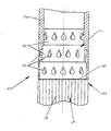
- the engine shaft 1 comprises a fiber composite plastic pipe 2, consisting of carbon fiber, that is, embedded in a plastic matrix carbon fibers, and connected to the ends of the engine shaft 1 with the fiber composite plastic pipe 2 power transmission element 3 made of steel.
- the power transmission element 3 has a toothing 4 in order to intervene in the transmission with the engine shaft serving, for example, as a low-pressure turbine shaft, and to drive the fan of a gas turbine engine.
- the power transmission element 3 is formed in two parts and has a made of a steel hardness, for example a case steel, existing toothing part 5 and a front side with this by a Rotationsreibsch beidestatt16 connected adapter part 7.
- the adapter part 7 connected to the fiber composite plastic pipe 2 is tapered in the longitudinal direction of the engine shaft 3 in stages 8 in order to provide a gradual transition between the two materials (steel and fiber composite material) with different properties.
- circumferentially arranged pylons 9 are arranged, around which the carbon fibers of the fiber composite plastic pipe 2 are laid, so that an intimate and firm connection between the fiber composite material and the force transmission element is produced.
- thermal expansion is -50 ° C to +180 despite the wide temperature range ° C (for a radial shaft) or + 250 ° C (for a low pressure shaft), in which the engine shaft 1 is operated, even at high temperatures, a firm connection and a secure transmission of very high forces between the fiber composite plastic pipe and the power transmission element or ensures the drive side and the output side of the engine shaft. Remaining differences in thermal expansion are also compensated by the training (opposite wall thicknesses) in the connection area between the adapter part 7 and fiber composite plastic pipe 2.
Landscapes
- Engineering & Computer Science (AREA)
- General Engineering & Computer Science (AREA)
- Mechanical Engineering (AREA)
- Chemical & Material Sciences (AREA)
- Materials Engineering (AREA)
- Ocean & Marine Engineering (AREA)
- Composite Materials (AREA)
- Shafts, Cranks, Connecting Bars, And Related Bearings (AREA)
- Pressure Welding/Diffusion-Bonding (AREA)
Abstract
Description
- Die Erfindung betrifft eine Triebwerkswelle in hybrider Bauweise, insbesondere die Niederdruckturbinenwelle oder die Radialwelle eines Gasturbinentriebwerks, bestehend aus einem Faserverbundkunststoffrohr, das an den Enden mit einem außen verzahnten Kraftübertragungselement verbunden ist.
- Um bei vermindertem Gewicht und begrenztem Außendurchmesser der Triebwerkswellen von Gasturbinentriebwerken dennoch hohe Drehmomente betriebssicher übertragen zu können, wurde bereits vorgeschlagen, die Triebwerkswelle aus einem im Wesentlichen aus Kohlenstofffasern bestehenden Faserverbundkunststoffrohr und an den Enden unlösbar in den Faserverbund eingebundenen, an der freien Außenfläche verzahnt ausgebildeten Lasteinleitungs- bzw. Lastableitungselementen aus Stahl herzustellen. Die Verbindung des Faserverbundmaterial mit dem metallischen Kraftübertragungselement erfolgt über einen an dieses angeformten, sich konisch verjüngenden Adapter, so dass eine geschäftete Verbindung mit einem allmählichen Übergang von einem dominierenden Faserbereich zu einem dominierenden metallischen Bereich geschaffen wird. Zur Übertragung von möglichst hohen Torsionskräften über den kleinen Verbindungsbereich sind an die Außenfläche des konischen Adapters Pylonen angeformt, an denen die Fasern umgelenkt und entsprechend dem Faserverlauf in dem Faserverbundmaterial geführt sind.
- Der Erfindung liegt die Aufgabe zugrunde, eine in hybrider Bauweise aus einem Faserverbundkunststoffrohr und einem Kraftübertragungselement aus Stahl bestehende Triebwerkswelle so auszubilden, dass im Triebwerksbetrieb auch bei erhöhten Temperaturen eine innige und feste Verbindung zwischen dem Faserverbundmaterial und dem Kraftübertragungselement und eine sichere Kraftübertragung sowie eine lange Lebensdauer der Triebwerkswelle gewährleistet sind.
- Erfindungsgemäß wird die Aufgabe mit einer gemäß den Merkmalen des Patentanspruchs 1 ausgebildeten Triebwerkswelle gelöst. Zweckmäßige Weiterbildungen der Erfindung sind Gegenstand der Unteransprüche.
- Der Kern der Erfindung besteht darin, dass das an den Wellenenden eines Faserverbundkunststoffrohres befestigte Kraftübertragungselement zweiteilig ausgebildet ist und ein aus einem Stahl bestimmter Härte bestehendes Verzahnungsteil sowie ein stirnseitig mit diesem verschweißtes, sich verjüngendes und zur Ausbildung einer geschäfteten Verbindung von dem Faserverbundmaterial umschlossenes Adapterteil umfasst, dessen Wärmeausdehnung etwa gleich dem Ausdehnungsverhalten des Faserverbundmaterials ist. Die annähernd gleiche Wärmeausdehnung der Werkstoffpaarung im Verbindungsbereich in Kombination mit der sich entgegengesetzt ändernden Materialstärke aufgrund der geschäfteten Verbindung gewährleistet auch bei hohen Betriebstemperaturen eine sichere Übertragung hoher Kräfte sowie eine Verminderung der Spannungen zwischen den unterschiedlichen Werkstoffen im Verbindungsbereich und eine lange Lebensdauer der Welle.
- In weiterer Ausbildung der Erfindung besteht das Faserverbundmaterial aus in ein hochtemperaturbeständiges Harzsystem eingebetteten Kohlenstofffasern und das Adapterteil aus einer Invarlegierung, deren jeweiliger thermischer Ausdehnungskoeffizient nahe Null und annähernd gleich ist.
- In Ausgestaltung der Erfindung sind das Verzahnungsteil und das Adapterteil durch eine Rotationsreibschweißverbindung miteinander verbunden.
- In weiterer Ausgestaltung der Erfindung sind auf der Außenumfangsfläche des Adapterteils Pylone zur Umführung und Halterung der Fasern des Faserverbundmaterials ausgebildet.
- In noch weiterer Ausgestaltung der Erfindung ist die Verjüngung des Adapterteils in Stufen ausgeführt und die Pylone sind auf den Stufen angeordnet.
- In weiterer Ausgestaltung der Erfindung besteht das Verzahnungsteil aus einem Einsatzstahl.
- Ein Ausführungsbeispiel der Erfindung wird anhand der Zeichnung, in deren einziger Figur eine in hybrider Bauweise ausgebildete Triebwerkswelle im Bereich der Verbindungsstelle zwischen dem Kraftübertragungselement und dem Faserverbundkunststoffrohr schematisch dargestellt ist, näher erläutert.
- Die Triebwerkswelle 1 umfasst ein Faserverbundkunststoffrohr 2, bestehend aus CFK, das heißt, in eine Kunststoffmatrix eingebetteten Kohlenstofffasern, und ein an den Enden der Triebwerkswelle 1 mit dem Faserverbundkunststoffrohr 2 verbundenes Kraftübertragungselement 3 aus Stahl. Das Kraftübertragungselement 3 weist eine Verzahnung 4 auf, um mit der - beispielsweise als Niederdruckturbinenwelle dienenden Triebwerkswelle - in ein Getriebe einzugreifen und den Fan eines Gasturbinentriebwerks anzutreiben. Das Kraftübertragungselement 3 ist zweiteilig ausgebildet und weist ein aus einem Stahl bestimmter Härte, zum Beispiel einem Einsatzstahl, bestehendes Verzahnungsteil 5 und ein stirnseitig mit diesem durch eine Rotationsreibschweißverbindung 6 verbundenes Adapterteil 7 auf. Das mit dem Faserverbundkunststoffrohr 2 verbundene Adapterteil 7 ist in Längsrichtung der Triebwerkswelle 3 in Stufen 8 verjüngt ausgebildet, um einen allmählichen Übergang zwischen den beiden Werkstoffen (Stahl und Faserverbundmaterial) mit unterschiedlichen Eigenschaften zu schaffen. In jeder Stufe sind in Umfangsrichtung angeordnete Pylone 9 angeordnet, um die die Kohlenstofffasern des Faserverbundkunststoffrohres 2 gelegt sind, so dass eine innige und feste Verbindung zwischen dem Faserverbundwerkstoff und dem Kraftübertragungselement hergestellt wird. Das separat gefertigte, sich verjüngende Adapterteil 7 besteht aus einer als Invarstahl bezeichneten Eisen-Nickel-Legierung, deren thermischer Ausdehnungskoeffizient bei 20°C etwa 2x10⁻⁶ K-1 beträgt und damit annähernd im Bereich der Wärmeausdehnung der Kohlenstofffasern (Ausdehnungskoeffizient a=0+/-1 10-6 K-1) des Faserverbundkunststoffrohres 2 liegt. Durch die synergistische Wirkung der geschäfteten Verbindung, mit der geringe Schubspannungen und eine gleichmäßige Übertragung der Schubspannungen erreicht wird, und der Ausbildung der Verbindungselemente aus Werkstoffen mit gleicher, das heißt nahe Null liegender Wärmeausdehnung ist trotz des großen Temperaturbereichs von -50°C bis +180 °C (für eine Radialwelle) bzw. +250°C (für eine Niederdruckwelle), in dem die Triebwerkswelle 1 betrieben wird, auch bei hohen Temperaturen eine feste Verbindung und eine sichere Übertragung der sehr hohen Kräfte zwischen dem Faserverbundkunststoffrohr und dem Kraftübertragungselement bzw. der Antriebsseite und der Abtriebsseite der Triebwerkswelle gewährleistet. Verbleibende Unterschiede in der Wärmeausdehnung werden zudem durch die geschäftete Ausbildung (entgegengesetzte Wandstärken) im Verbindungsbereich zwischen dem Adapterteil 7 und Faserverbundkunststoffrohr 2 ausgeglichen.
-
- 1
- Triebwerkswelle
- 2
- Faserverbundkunststoffrohr
- 3
- Kraftübertragungselement
- 4
- Verzahnung
- 5
- Verzahnungsteil
- 6
- Rotationsreibschweißverbindung
- 7
- Adapterteil
- 8
- Stufen von 7
- 9
- Pylone
Claims (7)
- Triebwerkswelle in hybrider Bauweise, insbesondere Niederdruckturbinenwelle oder Radialwelle eines Gasturbinentriebwerks, bestehend aus einem Faserverbundkunststoffrohr (2), das an den Enden mit einem außen verzahnten Kraftübertragungselement (3) verbunden ist, dadurch gekennzeichnet, dass das Kraftübertragungselement (3) zweiteilig ausgebildet ist und ein aus einem Stahl bestimmter Härte bestehendes Verzahnungsteil (5) sowie ein stirnseitig mit diesem verschweißtes, sich verjüngendes und zur Ausbildung einer geschäfteten Verbindung von dem Faserverbundmaterial umschlossenes Adapterteil (7) umfasst, dessen Wärmeausdehnung etwa gleich dem Ausdehnungsverhalten des Faserverbundmaterials ist.
- Triebwerkswelle nach Anspruch 1, dadurch gekennzeichnet, dass das Faserverbundmaterial aus in ein hochtemperaturbeständiges Harzsystem eingebetteten Kohlenstofffasern und das Adapterteil (7) aus einer Invarlegierung besteht, deren jeweiliger thermischer Ausdehnungskoeffizient nahe Null und annähernd gleich ist.
- Triebwerkswelle nach Anspruch 1, dadurch gekennzeichnet, dass das Verzahnungsteil (5) und das Adapterteil (7) durch eine Rotationsreibschweißverbindung miteinander verbunden sind.
- Triebwerkswelle nach Anspruch 1, dadurch gekennzeichnet, dass auf der Außenumfangsfläche des Adapterteils Pylone (9) zur Umführung und Halterung des Fasermaterials ausgebildet sind.
- Triebwerkswelle nach Anspruch 1, dadurch gekennzeichnet, dass die Verjüngung des Adapterteils (7) in Stufen (8) ausgeführt ist.
- Triebwerkswelle nach Anspruch 4 oder 5, dadurch gekennzeichnet, dass die Pylone (9) auf den Stufen (8) angeordnet sind.
- Triebwerkswelle nach Anspruch 1, dadurch gekennzeichnet, dass das Verzahnungsteil (5) aus einem Einsatzstahl besteht.
Applications Claiming Priority (1)
| Application Number | Priority Date | Filing Date | Title |
|---|---|---|---|
| DE102009037049A DE102009037049A1 (de) | 2009-08-13 | 2009-08-13 | Triebwerkswelle in hybrider Bauweise |
Publications (3)
| Publication Number | Publication Date |
|---|---|
| EP2284362A2 true EP2284362A2 (de) | 2011-02-16 |
| EP2284362A3 EP2284362A3 (de) | 2013-03-06 |
| EP2284362B1 EP2284362B1 (de) | 2018-09-05 |
Family
ID=42543036
Family Applications (1)
| Application Number | Title | Priority Date | Filing Date |
|---|---|---|---|
| EP10007922.7A Not-in-force EP2284362B1 (de) | 2009-08-13 | 2010-07-29 | Triebwerkswelle in hybrider Bauweise |
Country Status (3)
| Country | Link |
|---|---|
| US (1) | US8647011B2 (de) |
| EP (1) | EP2284362B1 (de) |
| DE (1) | DE102009037049A1 (de) |
Families Citing this family (4)
| Publication number | Priority date | Publication date | Assignee | Title |
|---|---|---|---|---|
| DE102012022198A1 (de) | 2012-11-13 | 2014-05-28 | Rolls-Royce Deutschland Ltd & Co Kg | Welle eines Gasturbinentriebwerks, insbesondere einer Radialwelle oder einer zur Maschinenachse in einem Winkel angeordneten Welle |
| DE102012022260A1 (de) | 2012-11-13 | 2014-05-28 | Rolls-Royce Deutschland Ltd & Co Kg | Verfahren zur Herstellung einer Welle eines Gasturbinentriebwerks, insbesondere einer Radialwelle oder einer zur Maschinenachse in einem Winkel angeordneten Welle |
| DE102016101212A1 (de) * | 2016-01-25 | 2017-07-27 | Terex MHPS IP Management GmbH | Tragstruktur für einen Kran und Kran hiermit |
| US11040512B2 (en) | 2017-11-08 | 2021-06-22 | Northrop Grumman Systems Corporation | Composite structures, forming apparatuses and related systems and methods |
Family Cites Families (20)
| Publication number | Priority date | Publication date | Assignee | Title |
|---|---|---|---|---|
| DE2946530A1 (de) * | 1979-11-17 | 1981-05-27 | Felten & Guilleaume Carlswerk AG, 5000 Köln | Antriebswelle aus faserverstaerktem kunststoff, mit festgewickelten endstuecken |
| US4834693A (en) * | 1980-06-26 | 1989-05-30 | Avco Corporation | Hybrid drive shaft |
| US4704918A (en) * | 1985-02-19 | 1987-11-10 | Kamatics Corporation | Composite material force or motion transmitting member |
| US4663819A (en) * | 1985-11-04 | 1987-05-12 | Eagle-Picher Industries, Inc. | Method of mounting a metal yoke to a composite tube |
| JPS63166519A (ja) * | 1986-12-27 | 1988-07-09 | Hitachi Constr Mach Co Ltd | 繊維強化樹脂製棒状体 |
| SE8800411L (sv) * | 1988-02-09 | 1989-08-10 | Ovako Steel Ab | Staal avsedda foer hoegt paakaenda konstruktionselement med stora krav paa formbarhet och utmattningshaallfasthet samt anvaendning daerav |
| US5018915A (en) * | 1989-09-08 | 1991-05-28 | Toshiba Kikai Kabushiki Kaisha | Spindles of machine tools |
| DE4119359C2 (de) * | 1990-06-23 | 1997-03-13 | Gkn Glaenzer Spicer | Antriebswelle |
| WO1993022127A1 (en) | 1992-04-24 | 1993-11-11 | United Technologies Corporation | Bonding of thermoplastic and thermoset composite structures to metallic structures |
| US5322580A (en) * | 1992-04-24 | 1994-06-21 | United Technologies Corporation | Bonding of thermoset composite structures to metal structures |
| US5407119A (en) * | 1992-12-10 | 1995-04-18 | American Research Corporation Of Virginia | Laser brazing for ceramic-to-metal joining |
| US5840386A (en) * | 1996-02-22 | 1998-11-24 | Praxair S.T. Technology, Inc. | Sleeve for a liquid transfer roll and method for producing it |
| US6309143B1 (en) * | 1998-05-27 | 2001-10-30 | Stanley Merjan | Composite pile with tapering lower portion and method for driving pile into granular soil |
| US6234912B1 (en) * | 1999-09-07 | 2001-05-22 | General Electric Company | High-stiffness composite shaft |
| US6927586B2 (en) * | 2000-03-06 | 2005-08-09 | Wentworth Laboratories, Inc. | Temperature compensated vertical pin probing device |
| JP4846103B2 (ja) * | 2001-02-07 | 2011-12-28 | 三菱レイヨン株式会社 | 繊維強化樹脂パイプ及びこれを用いた動力伝達シャフト |
| AT411883B (de) * | 2002-09-30 | 2004-07-26 | Voestalpine Schienen Gmbh | Verfahren zum metallischen verbinden von stäben |
| US7419435B2 (en) * | 2006-03-09 | 2008-09-02 | Northrop Grumman Corporation | Composite torque tube captured end fitting |
| US7682256B2 (en) * | 2006-09-13 | 2010-03-23 | Kop-Flex Inc. | Flange design for filament wound composite shaft |
| DE102008056002A1 (de) * | 2008-11-05 | 2010-05-06 | Rolls-Royce Deutschland Ltd & Co Kg | Triebwerkswelle aus einem Faserverbundkunststoffrohr mit metallischen Antriebs-und Abtriebszapfen |
-
2009
- 2009-08-13 DE DE102009037049A patent/DE102009037049A1/de not_active Withdrawn
-
2010
- 2010-07-29 EP EP10007922.7A patent/EP2284362B1/de not_active Not-in-force
- 2010-08-12 US US12/855,095 patent/US8647011B2/en not_active Expired - Fee Related
Non-Patent Citations (1)
| Title |
|---|
| None |
Also Published As
| Publication number | Publication date |
|---|---|
| US20110038666A1 (en) | 2011-02-17 |
| EP2284362A3 (de) | 2013-03-06 |
| DE102009037049A1 (de) | 2011-02-17 |
| US8647011B2 (en) | 2014-02-11 |
| EP2284362B1 (de) | 2018-09-05 |
Similar Documents
| Publication | Publication Date | Title |
|---|---|---|
| EP2184441B1 (de) | Triebwerkswelle für ein Gasturbinentriebwerk | |
| EP2241738B1 (de) | Einlaufkonus aus Faserverbundmaterial für ein Gasturbinentriebwerk | |
| EP2184440B1 (de) | Triebwerkswelle einer Gasturbine | |
| EP1975405B1 (de) | Verbindung von Bauteilen einer Windenergieanlage, Verwendung sowie Verfahren | |
| WO2009132612A1 (de) | Verfahren zur fertigung eines blattanschlusses eines rotorblatts, ein blattanschluss und ein befestigungselement für einen blattanschluss | |
| EP2284362B1 (de) | Triebwerkswelle in hybrider Bauweise | |
| DE102008058507A1 (de) | Ladeeinrichtung | |
| DE102018212864A1 (de) | Bremsscheibe und Verfahren zur Herstellung einer Bremsscheibe | |
| DE202007009801U1 (de) | Anordnung zum fluiddichten Verbinden von zwei Rohrenden aus unterschiedlichen Metallen | |
| DE19842821C2 (de) | Verbindung und Welle | |
| DE102010053078A1 (de) | Abgasturbolader | |
| WO2008155162A1 (de) | Axiallagerscheibe für einen turbomaschinenrotor einer turbomaschine und turbomaschinenrotor | |
| EP3707435A1 (de) | Rohrbrennkammer mit keramischer auskleidung | |
| DE102012111219A1 (de) | Windenergieanlagenkomponente | |
| DE19633627A1 (de) | Kupplungsvorrichtung für die Herstellung einer Rohrverbindung | |
| DE102012214405B4 (de) | Umwälzvorrichtung zum Umwälzen einer umgebenden Atmosphäre sowie Verfahren zur Herstellung einer derartigen Umwälzvorrichtung | |
| DE102008053222A1 (de) | Turbolader | |
| EP1707759B1 (de) | Gehäuse einer Turbomaschine | |
| DE102010034679A1 (de) | Dickstoffpumpe | |
| DE202016102887U1 (de) | Verbindungselement | |
| DE102011118989A1 (de) | Metallbalgkupplung - Balg aus Stahl verschweißt mit Anbaunaben aus Aluminium | |
| DE102014226557A1 (de) | Aufhängung zur Anbringung eines Innenbehälters an einem Außenbehälter eines kryogenen Druckbehälters sowie kryogener Druckbehälter | |
| DE202019003517U1 (de) | Rotorblattanschluss mit Insert und Dehnhülse | |
| DE102008020198B4 (de) | Düsenerweiterung für ein Triebwerk und Verfahren zur Herstellung und Kühlung einer Düsenerweiterung | |
| WO2011006692A1 (de) | Antriebsaggregat |
Legal Events
| Date | Code | Title | Description |
|---|---|---|---|
| PUAI | Public reference made under article 153(3) epc to a published international application that has entered the european phase |
Free format text: ORIGINAL CODE: 0009012 |
|
| AK | Designated contracting states |
Kind code of ref document: A2 Designated state(s): AL AT BE BG CH CY CZ DE DK EE ES FI FR GB GR HR HU IE IS IT LI LT LU LV MC MK MT NL NO PL PT RO SE SI SK SM TR |
|
| AX | Request for extension of the european patent |
Extension state: BA ME RS |
|
| PUAL | Search report despatched |
Free format text: ORIGINAL CODE: 0009013 |
|
| AK | Designated contracting states |
Kind code of ref document: A3 Designated state(s): AL AT BE BG CH CY CZ DE DK EE ES FI FR GB GR HR HU IE IS IT LI LT LU LV MC MK MT NL NO PL PT RO SE SI SK SM TR |
|
| AX | Request for extension of the european patent |
Extension state: BA ME RS |
|
| RIC1 | Information provided on ipc code assigned before grant |
Ipc: F01D 5/28 20060101ALI20130130BHEP Ipc: F01D 5/02 20060101AFI20130130BHEP |
|
| 17P | Request for examination filed |
Effective date: 20130423 |
|
| STAA | Information on the status of an ep patent application or granted ep patent |
Free format text: STATUS: EXAMINATION IS IN PROGRESS |
|
| 17Q | First examination report despatched |
Effective date: 20171006 |
|
| GRAP | Despatch of communication of intention to grant a patent |
Free format text: ORIGINAL CODE: EPIDOSNIGR1 |
|
| STAA | Information on the status of an ep patent application or granted ep patent |
Free format text: STATUS: GRANT OF PATENT IS INTENDED |
|
| INTG | Intention to grant announced |
Effective date: 20180223 |
|
| GRAS | Grant fee paid |
Free format text: ORIGINAL CODE: EPIDOSNIGR3 |
|
| GRAA | (expected) grant |
Free format text: ORIGINAL CODE: 0009210 |
|
| STAA | Information on the status of an ep patent application or granted ep patent |
Free format text: STATUS: THE PATENT HAS BEEN GRANTED |
|
| AK | Designated contracting states |
Kind code of ref document: B1 Designated state(s): AL AT BE BG CH CY CZ DE DK EE ES FI FR GB GR HR HU IE IS IT LI LT LU LV MC MK MT NL NO PL PT RO SE SI SK SM TR |
|
| REG | Reference to a national code |
Ref country code: GB Ref legal event code: FG4D Free format text: NOT ENGLISH |
|
| REG | Reference to a national code |
Ref country code: CH Ref legal event code: EP |
|
| REG | Reference to a national code |
Ref country code: AT Ref legal event code: REF Ref document number: 1038028 Country of ref document: AT Kind code of ref document: T Effective date: 20180915 |
|
| REG | Reference to a national code |
Ref country code: IE Ref legal event code: FG4D Free format text: LANGUAGE OF EP DOCUMENT: GERMAN |
|
| REG | Reference to a national code |
Ref country code: DE Ref legal event code: R096 Ref document number: 502010015318 Country of ref document: DE |
|
| REG | Reference to a national code |
Ref country code: NL Ref legal event code: MP Effective date: 20180905 |
|
| REG | Reference to a national code |
Ref country code: LT Ref legal event code: MG4D |
|
| PG25 | Lapsed in a contracting state [announced via postgrant information from national office to epo] |
Ref country code: BG Free format text: LAPSE BECAUSE OF FAILURE TO SUBMIT A TRANSLATION OF THE DESCRIPTION OR TO PAY THE FEE WITHIN THE PRESCRIBED TIME-LIMIT Effective date: 20181205 Ref country code: SE Free format text: LAPSE BECAUSE OF FAILURE TO SUBMIT A TRANSLATION OF THE DESCRIPTION OR TO PAY THE FEE WITHIN THE PRESCRIBED TIME-LIMIT Effective date: 20180905 Ref country code: GR Free format text: LAPSE BECAUSE OF FAILURE TO SUBMIT A TRANSLATION OF THE DESCRIPTION OR TO PAY THE FEE WITHIN THE PRESCRIBED TIME-LIMIT Effective date: 20181206 Ref country code: LT Free format text: LAPSE BECAUSE OF FAILURE TO SUBMIT A TRANSLATION OF THE DESCRIPTION OR TO PAY THE FEE WITHIN THE PRESCRIBED TIME-LIMIT Effective date: 20180905 Ref country code: NO Free format text: LAPSE BECAUSE OF FAILURE TO SUBMIT A TRANSLATION OF THE DESCRIPTION OR TO PAY THE FEE WITHIN THE PRESCRIBED TIME-LIMIT Effective date: 20181205 Ref country code: FI Free format text: LAPSE BECAUSE OF FAILURE TO SUBMIT A TRANSLATION OF THE DESCRIPTION OR TO PAY THE FEE WITHIN THE PRESCRIBED TIME-LIMIT Effective date: 20180905 |
|
| PG25 | Lapsed in a contracting state [announced via postgrant information from national office to epo] |
Ref country code: HR Free format text: LAPSE BECAUSE OF FAILURE TO SUBMIT A TRANSLATION OF THE DESCRIPTION OR TO PAY THE FEE WITHIN THE PRESCRIBED TIME-LIMIT Effective date: 20180905 Ref country code: LV Free format text: LAPSE BECAUSE OF FAILURE TO SUBMIT A TRANSLATION OF THE DESCRIPTION OR TO PAY THE FEE WITHIN THE PRESCRIBED TIME-LIMIT Effective date: 20180905 Ref country code: AL Free format text: LAPSE BECAUSE OF FAILURE TO SUBMIT A TRANSLATION OF THE DESCRIPTION OR TO PAY THE FEE WITHIN THE PRESCRIBED TIME-LIMIT Effective date: 20180905 Ref country code: ES Free format text: LAPSE BECAUSE OF FAILURE TO SUBMIT A TRANSLATION OF THE DESCRIPTION OR TO PAY THE FEE WITHIN THE PRESCRIBED TIME-LIMIT Effective date: 20180905 |
|
| PG25 | Lapsed in a contracting state [announced via postgrant information from national office to epo] |
Ref country code: RO Free format text: LAPSE BECAUSE OF FAILURE TO SUBMIT A TRANSLATION OF THE DESCRIPTION OR TO PAY THE FEE WITHIN THE PRESCRIBED TIME-LIMIT Effective date: 20180905 Ref country code: IT Free format text: LAPSE BECAUSE OF FAILURE TO SUBMIT A TRANSLATION OF THE DESCRIPTION OR TO PAY THE FEE WITHIN THE PRESCRIBED TIME-LIMIT Effective date: 20180905 Ref country code: CZ Free format text: LAPSE BECAUSE OF FAILURE TO SUBMIT A TRANSLATION OF THE DESCRIPTION OR TO PAY THE FEE WITHIN THE PRESCRIBED TIME-LIMIT Effective date: 20180905 Ref country code: PL Free format text: LAPSE BECAUSE OF FAILURE TO SUBMIT A TRANSLATION OF THE DESCRIPTION OR TO PAY THE FEE WITHIN THE PRESCRIBED TIME-LIMIT Effective date: 20180905 Ref country code: IS Free format text: LAPSE BECAUSE OF FAILURE TO SUBMIT A TRANSLATION OF THE DESCRIPTION OR TO PAY THE FEE WITHIN THE PRESCRIBED TIME-LIMIT Effective date: 20190105 Ref country code: NL Free format text: LAPSE BECAUSE OF FAILURE TO SUBMIT A TRANSLATION OF THE DESCRIPTION OR TO PAY THE FEE WITHIN THE PRESCRIBED TIME-LIMIT Effective date: 20180905 Ref country code: EE Free format text: LAPSE BECAUSE OF FAILURE TO SUBMIT A TRANSLATION OF THE DESCRIPTION OR TO PAY THE FEE WITHIN THE PRESCRIBED TIME-LIMIT Effective date: 20180905 |
|
| PG25 | Lapsed in a contracting state [announced via postgrant information from national office to epo] |
Ref country code: SM Free format text: LAPSE BECAUSE OF FAILURE TO SUBMIT A TRANSLATION OF THE DESCRIPTION OR TO PAY THE FEE WITHIN THE PRESCRIBED TIME-LIMIT Effective date: 20180905 Ref country code: PT Free format text: LAPSE BECAUSE OF FAILURE TO SUBMIT A TRANSLATION OF THE DESCRIPTION OR TO PAY THE FEE WITHIN THE PRESCRIBED TIME-LIMIT Effective date: 20190105 Ref country code: SK Free format text: LAPSE BECAUSE OF FAILURE TO SUBMIT A TRANSLATION OF THE DESCRIPTION OR TO PAY THE FEE WITHIN THE PRESCRIBED TIME-LIMIT Effective date: 20180905 |
|
| REG | Reference to a national code |
Ref country code: DE Ref legal event code: R097 Ref document number: 502010015318 Country of ref document: DE |
|
| PLBE | No opposition filed within time limit |
Free format text: ORIGINAL CODE: 0009261 |
|
| STAA | Information on the status of an ep patent application or granted ep patent |
Free format text: STATUS: NO OPPOSITION FILED WITHIN TIME LIMIT |
|
| PG25 | Lapsed in a contracting state [announced via postgrant information from national office to epo] |
Ref country code: DK Free format text: LAPSE BECAUSE OF FAILURE TO SUBMIT A TRANSLATION OF THE DESCRIPTION OR TO PAY THE FEE WITHIN THE PRESCRIBED TIME-LIMIT Effective date: 20180905 |
|
| 26N | No opposition filed |
Effective date: 20190606 |
|
| PG25 | Lapsed in a contracting state [announced via postgrant information from national office to epo] |
Ref country code: SI Free format text: LAPSE BECAUSE OF FAILURE TO SUBMIT A TRANSLATION OF THE DESCRIPTION OR TO PAY THE FEE WITHIN THE PRESCRIBED TIME-LIMIT Effective date: 20180905 |
|
| PG25 | Lapsed in a contracting state [announced via postgrant information from national office to epo] |
Ref country code: MC Free format text: LAPSE BECAUSE OF FAILURE TO SUBMIT A TRANSLATION OF THE DESCRIPTION OR TO PAY THE FEE WITHIN THE PRESCRIBED TIME-LIMIT Effective date: 20180905 |
|
| REG | Reference to a national code |
Ref country code: CH Ref legal event code: PL |
|
| PG25 | Lapsed in a contracting state [announced via postgrant information from national office to epo] |
Ref country code: TR Free format text: LAPSE BECAUSE OF FAILURE TO SUBMIT A TRANSLATION OF THE DESCRIPTION OR TO PAY THE FEE WITHIN THE PRESCRIBED TIME-LIMIT Effective date: 20180905 |
|
| REG | Reference to a national code |
Ref country code: BE Ref legal event code: MM Effective date: 20190731 |
|
| PG25 | Lapsed in a contracting state [announced via postgrant information from national office to epo] |
Ref country code: LU Free format text: LAPSE BECAUSE OF NON-PAYMENT OF DUE FEES Effective date: 20190729 Ref country code: CH Free format text: LAPSE BECAUSE OF NON-PAYMENT OF DUE FEES Effective date: 20190731 Ref country code: BE Free format text: LAPSE BECAUSE OF NON-PAYMENT OF DUE FEES Effective date: 20190731 Ref country code: LI Free format text: LAPSE BECAUSE OF NON-PAYMENT OF DUE FEES Effective date: 20190731 |
|
| PG25 | Lapsed in a contracting state [announced via postgrant information from national office to epo] |
Ref country code: IE Free format text: LAPSE BECAUSE OF NON-PAYMENT OF DUE FEES Effective date: 20190729 |
|
| REG | Reference to a national code |
Ref country code: AT Ref legal event code: MM01 Ref document number: 1038028 Country of ref document: AT Kind code of ref document: T Effective date: 20190729 |
|
| PGFP | Annual fee paid to national office [announced via postgrant information from national office to epo] |
Ref country code: FR Payment date: 20200728 Year of fee payment: 11 Ref country code: DE Payment date: 20200928 Year of fee payment: 11 Ref country code: GB Payment date: 20200724 Year of fee payment: 11 |
|
| PG25 | Lapsed in a contracting state [announced via postgrant information from national office to epo] |
Ref country code: AT Free format text: LAPSE BECAUSE OF NON-PAYMENT OF DUE FEES Effective date: 20190729 |
|
| PG25 | Lapsed in a contracting state [announced via postgrant information from national office to epo] |
Ref country code: CY Free format text: LAPSE BECAUSE OF FAILURE TO SUBMIT A TRANSLATION OF THE DESCRIPTION OR TO PAY THE FEE WITHIN THE PRESCRIBED TIME-LIMIT Effective date: 20180905 |
|
| PG25 | Lapsed in a contracting state [announced via postgrant information from national office to epo] |
Ref country code: HU Free format text: LAPSE BECAUSE OF FAILURE TO SUBMIT A TRANSLATION OF THE DESCRIPTION OR TO PAY THE FEE WITHIN THE PRESCRIBED TIME-LIMIT; INVALID AB INITIO Effective date: 20100729 Ref country code: MT Free format text: LAPSE BECAUSE OF FAILURE TO SUBMIT A TRANSLATION OF THE DESCRIPTION OR TO PAY THE FEE WITHIN THE PRESCRIBED TIME-LIMIT Effective date: 20180905 |
|
| REG | Reference to a national code |
Ref country code: DE Ref legal event code: R082 Ref document number: 502010015318 Country of ref document: DE |
|
| REG | Reference to a national code |
Ref country code: DE Ref legal event code: R119 Ref document number: 502010015318 Country of ref document: DE |
|
| GBPC | Gb: european patent ceased through non-payment of renewal fee |
Effective date: 20210729 |
|
| PG25 | Lapsed in a contracting state [announced via postgrant information from national office to epo] |
Ref country code: GB Free format text: LAPSE BECAUSE OF NON-PAYMENT OF DUE FEES Effective date: 20210729 Ref country code: DE Free format text: LAPSE BECAUSE OF NON-PAYMENT OF DUE FEES Effective date: 20220201 |
|
| PG25 | Lapsed in a contracting state [announced via postgrant information from national office to epo] |
Ref country code: FR Free format text: LAPSE BECAUSE OF NON-PAYMENT OF DUE FEES Effective date: 20210731 |
|
| PG25 | Lapsed in a contracting state [announced via postgrant information from national office to epo] |
Ref country code: MK Free format text: LAPSE BECAUSE OF FAILURE TO SUBMIT A TRANSLATION OF THE DESCRIPTION OR TO PAY THE FEE WITHIN THE PRESCRIBED TIME-LIMIT Effective date: 20180905 |