EP2284310A1 - A tumble dryer with a heat pump system and a method for controlling a heat pump system for a tumble dryer - Google Patents
A tumble dryer with a heat pump system and a method for controlling a heat pump system for a tumble dryer Download PDFInfo
- Publication number
- EP2284310A1 EP2284310A1 EP09010370A EP09010370A EP2284310A1 EP 2284310 A1 EP2284310 A1 EP 2284310A1 EP 09010370 A EP09010370 A EP 09010370A EP 09010370 A EP09010370 A EP 09010370A EP 2284310 A1 EP2284310 A1 EP 2284310A1
- Authority
- EP
- European Patent Office
- Prior art keywords
- air stream
- temperature
- drum
- physical parameter
- refrigerant
- Prior art date
- Legal status (The legal status is an assumption and is not a legal conclusion. Google has not performed a legal analysis and makes no representation as to the accuracy of the status listed.)
- Granted
Links
- 238000000034 method Methods 0.000 title claims abstract description 26
- 239000003507 refrigerant Substances 0.000 claims abstract description 65
- 238000011161 development Methods 0.000 claims abstract description 19
- 238000011156 evaluation Methods 0.000 claims abstract description 10
- 230000008878 coupling Effects 0.000 claims abstract description 8
- 238000010168 coupling process Methods 0.000 claims abstract description 8
- 238000005859 coupling reaction Methods 0.000 claims abstract description 8
- 238000012545 processing Methods 0.000 claims abstract description 4
- 238000001035 drying Methods 0.000 claims description 64
- 230000007423 decrease Effects 0.000 claims description 31
- XLYOFNOQVPJJNP-UHFFFAOYSA-N water Substances O XLYOFNOQVPJJNP-UHFFFAOYSA-N 0.000 claims description 11
- 230000003247 decreasing effect Effects 0.000 claims description 6
- 230000009467 reduction Effects 0.000 claims description 6
- 238000001514 detection method Methods 0.000 claims description 5
- 238000001704 evaporation Methods 0.000 claims description 4
- 230000008020 evaporation Effects 0.000 claims description 4
- 230000004044 response Effects 0.000 claims description 3
- 238000010586 diagram Methods 0.000 description 17
- 238000001914 filtration Methods 0.000 description 5
- 230000008569 process Effects 0.000 description 5
- 230000008859 change Effects 0.000 description 3
- 238000001816 cooling Methods 0.000 description 3
- 238000005516 engineering process Methods 0.000 description 2
- 238000012986 modification Methods 0.000 description 2
- 230000004048 modification Effects 0.000 description 2
- 238000007405 data analysis Methods 0.000 description 1
- 238000013461 design Methods 0.000 description 1
- 238000005265 energy consumption Methods 0.000 description 1
- 238000010438 heat treatment Methods 0.000 description 1
- 229920000136 polysorbate Polymers 0.000 description 1
Images


Classifications
-
- D—TEXTILES; PAPER
- D06—TREATMENT OF TEXTILES OR THE LIKE; LAUNDERING; FLEXIBLE MATERIALS NOT OTHERWISE PROVIDED FOR
- D06F—LAUNDERING, DRYING, IRONING, PRESSING OR FOLDING TEXTILE ARTICLES
- D06F58/00—Domestic laundry dryers
- D06F58/32—Control of operations performed in domestic laundry dryers
- D06F58/34—Control of operations performed in domestic laundry dryers characterised by the purpose or target of the control
- D06F58/48—Control of the energy consumption
-
- D—TEXTILES; PAPER
- D06—TREATMENT OF TEXTILES OR THE LIKE; LAUNDERING; FLEXIBLE MATERIALS NOT OTHERWISE PROVIDED FOR
- D06F—LAUNDERING, DRYING, IRONING, PRESSING OR FOLDING TEXTILE ARTICLES
- D06F2103/00—Parameters monitored or detected for the control of domestic laundry washing machines, washer-dryers or laundry dryers
- D06F2103/02—Characteristics of laundry or load
- D06F2103/04—Quantity, e.g. weight or variation of weight
-
- D—TEXTILES; PAPER
- D06—TREATMENT OF TEXTILES OR THE LIKE; LAUNDERING; FLEXIBLE MATERIALS NOT OTHERWISE PROVIDED FOR
- D06F—LAUNDERING, DRYING, IRONING, PRESSING OR FOLDING TEXTILE ARTICLES
- D06F2103/00—Parameters monitored or detected for the control of domestic laundry washing machines, washer-dryers or laundry dryers
- D06F2103/02—Characteristics of laundry or load
- D06F2103/08—Humidity
- D06F2103/10—Humidity expressed as capacitance or resistance
-
- D—TEXTILES; PAPER
- D06—TREATMENT OF TEXTILES OR THE LIKE; LAUNDERING; FLEXIBLE MATERIALS NOT OTHERWISE PROVIDED FOR
- D06F—LAUNDERING, DRYING, IRONING, PRESSING OR FOLDING TEXTILE ARTICLES
- D06F2103/00—Parameters monitored or detected for the control of domestic laundry washing machines, washer-dryers or laundry dryers
- D06F2103/28—Air properties
- D06F2103/32—Temperature
-
- D—TEXTILES; PAPER
- D06—TREATMENT OF TEXTILES OR THE LIKE; LAUNDERING; FLEXIBLE MATERIALS NOT OTHERWISE PROVIDED FOR
- D06F—LAUNDERING, DRYING, IRONING, PRESSING OR FOLDING TEXTILE ARTICLES
- D06F2103/00—Parameters monitored or detected for the control of domestic laundry washing machines, washer-dryers or laundry dryers
- D06F2103/28—Air properties
- D06F2103/34—Humidity
-
- D—TEXTILES; PAPER
- D06—TREATMENT OF TEXTILES OR THE LIKE; LAUNDERING; FLEXIBLE MATERIALS NOT OTHERWISE PROVIDED FOR
- D06F—LAUNDERING, DRYING, IRONING, PRESSING OR FOLDING TEXTILE ARTICLES
- D06F2103/00—Parameters monitored or detected for the control of domestic laundry washing machines, washer-dryers or laundry dryers
- D06F2103/50—Parameters monitored or detected for the control of domestic laundry washing machines, washer-dryers or laundry dryers related to heat pumps, e.g. pressure or flow rate
-
- D—TEXTILES; PAPER
- D06—TREATMENT OF TEXTILES OR THE LIKE; LAUNDERING; FLEXIBLE MATERIALS NOT OTHERWISE PROVIDED FOR
- D06F—LAUNDERING, DRYING, IRONING, PRESSING OR FOLDING TEXTILE ARTICLES
- D06F2105/00—Systems or parameters controlled or affected by the control systems of washing machines, washer-dryers or laundry dryers
- D06F2105/26—Heat pumps
-
- D—TEXTILES; PAPER
- D06—TREATMENT OF TEXTILES OR THE LIKE; LAUNDERING; FLEXIBLE MATERIALS NOT OTHERWISE PROVIDED FOR
- D06F—LAUNDERING, DRYING, IRONING, PRESSING OR FOLDING TEXTILE ARTICLES
- D06F58/00—Domestic laundry dryers
- D06F58/20—General details of domestic laundry dryers
- D06F58/206—Heat pump arrangements
-
- Y—GENERAL TAGGING OF NEW TECHNOLOGICAL DEVELOPMENTS; GENERAL TAGGING OF CROSS-SECTIONAL TECHNOLOGIES SPANNING OVER SEVERAL SECTIONS OF THE IPC; TECHNICAL SUBJECTS COVERED BY FORMER USPC CROSS-REFERENCE ART COLLECTIONS [XRACs] AND DIGESTS
- Y02—TECHNOLOGIES OR APPLICATIONS FOR MITIGATION OR ADAPTATION AGAINST CLIMATE CHANGE
- Y02B—CLIMATE CHANGE MITIGATION TECHNOLOGIES RELATED TO BUILDINGS, e.g. HOUSING, HOUSE APPLIANCES OR RELATED END-USER APPLICATIONS
- Y02B40/00—Technologies aiming at improving the efficiency of home appliances, e.g. induction cooking or efficient technologies for refrigerators, freezers or dish washers
Definitions
- the present invention relates to a tumble dryer with a heat pump system according to the preamble of claim 1. Further, the present invention relates to method for controlling a heat pump system for a tumble dryer according to claim 9.
- a usual tumble dryer with heat pump technology uses a reciprocating fixed speed compressor for the refrigerant circuit.
- This type of compressor has several disadvantages.
- the design of the compressor is very complex. This compressor is very big and needs a large space. Such a compressor works in an on/off-mode, so that the operating parameters of said compressor cannot be controlled during the operation.
- DE 10 2005 041 145 A1 discloses a tumble dryer with a heat pump system.
- the refrigerant circuit of said heat pump system includes a compressor with a variable power output.
- the power output of the compressor depends either on detected parameters or on a predetermined scheme.
- the object of the present invention is achieved by the tumble dryer according to claim 1.
- a central processing unit which is arranged to evaluate the time development of the physical parameter, and which reduces the rotation speed of the compressor according to the evaluation of the time development of the physical parameter.
- the control unit of for controlling the rotation speed of the compressor can be part of the central processing unit.
- a physical parameter is selected whose time development is an indicator for the time development of the dryness of the laundry.
- the evaluation of its time development allows to detect an increasing dryness of the laundry, and according to the increasing dryness the rotation speed of the compressor is reduced, e.g. continuously or gradually or in one or more steps.
- the main idea of the present invention is the reduction of the rotation speed of the compressor when the water content in the laundry decreases.
- the time development of one or more physical parameters corresponding with the dryness of the laundry is a suitable and efficient criterion for controlling the rotation speed of the compressor. Often the values of such physical parameters change abruptly, when the laundry becomes drier. Thus, the increasing dryness of the laundry is recognized by means of said physical parameters and the rotation speed of the compressor can be reduced.
- the reduced rotation speed of the compressor is sufficient and saves energy, since the excess of energy could not be used and would be lost. That phase of the drying procedure, in which the water content of the laundry is clearly reduced, is referred as a residual drying phase.
- the first heat exchanger is formed as a condenser of the heat pump system and the second heat exchanger is formed as an evaporator of the heat pump system.
- the physical parameter is the difference between the temperature of the air stream at the drum inlet of the air stream and the temperature of the air stream at the drum outlet of the air stream.
- the difference between the temperature at the drum inlet and the temperature at the drum outlet decreases with the increasing dryness of the laundry.
- the physical parameter may be the temperature of the air stream at the air outlet of the second heat exchanger.
- the temperature at the air outlet of the second heat exchanger also decreases with the increasing dryness of the laundry.
- the physical parameter may be the difference between the temperature of the air stream at the air inlet of the second heat exchanger (which is identical or at least comparable to the temperature of the air stream at the drum outlet for the air stream, thus, this temperature could also be used) and the temperature at the air outlet of the second heat exchanger.
- the difference between the temperature at the air inlet and the temperature at the air outlet of the second heat exchanger increases with the increasing dryness of the laundry.
- the physical parameter is the electrical impedance of the laundry within the drum.
- the electrical impedance of laundry within the drum increases with the increasing dryness of the laundry.
- the physical parameter is the temperature of the refrigerant in the refrigerant outlet of the second heat exchanger. Said temperature decreases with the increasing dryness of the laundry.
- the physical parameter may be the relative humidity of the drying air within the drum.
- the relative humidity of the drying air within the drum decreases with the increasing dryness of the laundry.
- At least one sensor for detecting the relative humidity of the drying air is arranged within the drum and/or at the drum outlet.
- the object of the present invention is further achieved by the method for controlling a heat pump system for a tumble dryer according to claim 9.
- the method is provided for a tumble dryer with at least one heat pump system comprising an air stream circuit including at least one drum for receiving laundry to be dried, at least one refrigerant circuit including at least one compressor with a variable rotation speed, a first heat exchanger for a thermal coupling between the air stream circuit and the refrigerant circuit and a second heat exchanger for a further thermal coupling between the air stream circuit and the refrigerant circuit.
- the method is provided for a tumble dryer according to the invention, as described above.
- the method comprises the following steps:
- a physical parameter is selected whose time development is an indicator for the time development of the dryness of the laundry.
- the evaluation of its time development allows to detect an increasing dryness of the laundry, and according to the increasing dryness the rotation speed of the compressor is reduced, e.g. continuously or gradually or in one or more steps.
- the main idea of the inventive method is the reduction of the rotation speed of the compressor when the water content in the laundry decreases.
- the time development of one or more physical parameters corresponding with the dryness of the laundry is a suitable and efficient criterion for controlling the rotation speed of the compressor. Often such kinds of physical parameters are changed abruptly, when the laundry becomes drier.
- the increasing dryness of the laundry is recognized by means of said physical parameters and the rotation speed of the compressor is reduced.
- the reduced rotation speed of the compressor is sufficient for the further drying procedure and saves energy, since the excess of additional energy could not be used and would be lost.
- the physical parameter is the difference between the temperature of the air stream at the drum inlet of the air stream and the temperature of the air steam at the drum outlet of the air stream, which difference decreases with the increasing dryness of the laundry.
- the physical parameter may be the temperature of the air stream at the air outlet of the second heat exchanger, which temperature also decreases with the increasing dryness of the laundry.
- the physical parameter may be the difference between the temperature of the air stream at an air inlet of the second heat exchanger and the temperature of the air stream at the air outlet of the second heat exchanger, which difference increases with the increasing dryness of the laundry.
- the physical parameter is the electrical impedance of the laundry within the drum, which electrical impedance increases with the increasing dryness of the laundry.
- the physical parameter is the temperature of the refrigerant in the refrigerant outlet of the second heat exchanger, which temperature decreases with the increasing dryness of the laundry.
- the method according to the present invention provides for a reduction of rotation speed of the compressor after a delay time interval (DTI) has elapsed from the detection of the maximum temperature value of the refrigerant at evaporator outlet.
- DTI delay time interval
- the physical parameter may be the relative humidity of the drying air within the drum.
- the relative humidity of the drying air within the drum decreases with the increasing dryness of the laundry.
- At least one sensor for detecting the relative humidity of the drying air is arranged within the drum and/or at the drum outlet.
- FIG 1 illustrates a schematic diagram of a tumble dryer with a heat pump system according to a preferred embodiment of the present invention.
- the tumble dryer with a heat pump system comprises an air stream circuit 10, a drum 12, a refrigerant circuit 14, a compressor 16, a first heat exchanger 18, a second heat exchanger 20 and a control unit 22.
- the drum 12 is an integrated part of the air stream circuit 10.
- the drum 12 is provided for receiving laundry.
- the compressor 16 is an integrated part of the refrigerant circuit 14.
- the air stream circuit 10 and the refrigerant circuit 14 are thermally coupled by the first heat exchanger 18 and the second heat exchanger 20.
- the first heat exchanger works as a condenser 18.
- the second heat exchanger works as an evaporator 20.
- the control unit 22 is provided for controlling the compressor 16. In particular, the control unit 22 is provided for controlling the rotation speed of the compressor 16.
- the tumble dryer may comprise several kinds of sensor elements, which are not shown in FIG 1 .
- the sensor elements may be provided for detecting the temperature, the relative humidity and/or the electrical impedance at suitable positions of the tumble dryer.
- the sensor elements for detecting the temperature of the air stream may be arranged at a drum air inlet 24, at a drum air outlet 26, at an evaporator air inlet 28 and/or at an evaporator air outlet 30.
- the air stream is generated by at least one fan, which is not shown in FIG 1 .
- the fan may be arranged at or in the environment of a drum air inlet 24.
- the air stream circulates counter-clockwise in the air stream circuit 10.
- the air stream circuit 10 is a closed circuit.
- a refrigerant flows in the refrigerant circuit 14.
- the refrigerant flows counter-clockwise in the refrigerant circuit 14.
- the refrigerant is compressed and heated by the compressor 16.
- the heated refrigerant reaches the condenser 18.
- the condenser 18 the air stream is heated and the refrigerant is condensed and cooled down.
- the refrigerant is cooled down and preferably expanded by suitable means, which are not shown in FIG 1 .
- the evaporator 20 the air stream is cooled down and the refrigerant is warmed up.
- FIG 2 illustrates a schematic diagram of a temperature TDI at the drum air inlet 24, a temperature TDO at the drum air outlet 26 and a temperature TEO at the evaporator air outlet 30 as a function of the time t.
- FIG 2 clarifies that the dry process can be subdivided into four phases 40, 42, 44 and 46.
- the temperatures TDI, TDO and TEO increase.
- the temperature TDI at THE drum inlet 11 is plainly higher than the temperature TDO and TEO at the drum outlet 11 and evaporator outlet 11, respectively.
- the temperature TDO at the drum outlet 11 and the temperature TEO at the evaporator outlet 11 remain substantially within the same order of magnitude at the end of the warm up phase 40.
- a main drying phase 42 the differences between the temperature TDI on the one hand and the temperatures TDO and TEO on the other hand are substantially maintained. In the main drying phase 42 all the temperatures TDI, TDO and TEO increase slowly.
- a residual drying phase 44 the temperatures TDI and TEO remain substantially constant, while the temperature TDO increases in a relevant way.
- the moisture of the laundry in the drum 12 is reduced, since the energy introduced into the drum 12 by the air stream is not completely used for extracting the water from the laundry.
- the unused energy causes the increase of temperature in the air stream.
- the temperature difference between TDI and TDO in the main drying phase 42 is about 20°C. This means that a huge part of the heat carried by the air stream is effectively used to extract the water from the laundry. However, this does not happen in the subsequent residual drying phase 44, in which the temperature difference between TDI and TDO sinks down to about 5°C. The air stream does not exchange such an amount of heat with the water in the laundry and keeps most of its energy content, which results in the increased temperature TDO. This energy cannot be used and is effectively lost.
- the decreasing temperature difference between TDI and TDO could also be considered as an increasing temperature difference between TDO and TEO. Both temperature differences can be used as parameters for controlling the drying process.
- the flow rate of the refrigerant circuit 14 can be controlled by setting up the rotation speed of the compressor 16.
- the rotation speed of the compressor 16 can be controlled in dependence of the temperature of the air stream. During the warm up phase 40 the rotation speed of the compressor 16 is usually set at its maximum value in order to speed up the heating up of the refrigerant circuit 14.
- the beginning of the residual drying phase 44 in which the temperature difference between TDI and TDO decreases rapidly, can be identified by the detected temperature TDO or by the detected temperature difference between TDO on the on hand and TDI or TEO on the other hand.
- the rotation speed of the compressor 16 is reduced in order to decrease the energy given to the air stream circuit 10. Thus, only that energy, which can really be used for drying the last part of the laundry, is input to the air stream circuit 10.
- the following detected or detectable parameters can be used for controlling the rotation speed of the compressor 16:
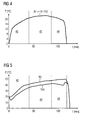
- FIG 3 illustrates a schematic diagram of a difference ⁇ T between the temperature TEI of the air stream at the evaporator air inlet 28 and the temperature TEO of the air stream at the evaporator air outlet 30 as a function of the time t according to the preferred embodiment of the present invention.
- FIG 4 illustrates a schematic diagram of a difference ⁇ T between the temperature TDI of the air stream at the drum air inlet 24 and the temperature TDO of the air stream at the drum air outlet 26 as a function of the time t according to the preferred embodiment of the present invention.
- the difference ⁇ T between the temperature TDI at the drum inlet 24 and the temperature TDO at the drum outlet 26 as function of the time t is substantially constant during the main drying phase 42 and decreases in the residual drying phase 44.
- FIG 5 illustrates a schematic diagram of the temperature TEI of the air stream at the evaporator air inlet 28 and the temperature TEO of the air stream at the evaporator air outlet 30 as functions of the time t according to the preferred embodiment of the present invention.
- the temperature TEI at the evaporator air inlet 28 as function of the time t substantially increases during the main drying phase 42 and the residual drying phase 44.
- the temperature TEO at the evaporator air outlet 30 as function of the time t increases during the main drying phase 42 and decreases in the residual drying phase 44.
- the functions shown in FIG 3 , FIG 4 and FIG 5 are suitable to recognize the beginning of the residual drying phase 44. The detection of the corresponding values of these temperatures and differences of temperatures as function of the time t allows the identification of the residual drying phase 44.
- Such diagrams of temperatures or differences of temperatures as function of the time t are be kept as feedback reference to introduce always the optimum energy level by recognizing the beginning of the residual drying phase 44 and changing the rotation speed of the compressor 16.
- a minimum value for the rotation speed of the compressor 16 can be set over the rotation speed range of the compressor 16.
- the aim of controlling the rotation speed of the compressor 16 is to avoid fluctuations of the temperatures and of the differences of temperatures. Said temperatures and of the differences of temperatures should be kept constant as much as possible.
- the control of the rotation speed of the compressor 16 allows during the residual drying phase 44 the same or a similar developing of the temperatures and differences of temperatures as in the main drying phase 42.
- FIG 6 illustrates a schematic diagram of an electrical impedance Z of the laundry in the drum 12 as a function of the time t according to further embodiment of the present invention.
- the proper electrical impedance is a function oscillating with big amplitudes at high frequencies.
- the electrical impedance Z shown in FIG 6 is a filtered function of said proper impedance.
- the tumble dryer may have a set of electrodes within the drum 12 or at the drum inlet 24 or drum outlet 26 in order to detect the conductivity and/or the resistance of the laundry inside the drum 12.
- the conductivity and the resistance of the laundry are a property depending on the dryness of the laundry.
- the electrical impedance Z of the laundry is always increasing during the drying procedure.
- the laundry closes an electrical circuit comprising different metallic sensors contacting the clothes and electrically insulated one from the other such as different portions of the metallic drum, metallic part of the lifters and parts of the drum, different parts of the lifters, electrodes adapted to contact the laundry arranged at the clothes loading/unloading opening and portions of the drum and different electrodes.
- FIG 7 illustrates a schematic diagram of the temperature TDI at the drum air inlet 24, the temperature TDO at the drum air outlet 26 and a refrigerant temperature TF at the refrigerant outlet of the evaporator 20 as functions of the time t according to a further embodiment of the present invention.
- the refrigerant temperature TF at the refrigerant outlet of the evaporator 20 as functions of the time t is similar to the function of the temperature TEO of the air stream at the evaporator air outlet 30 in FIG 2 .
- some differences exist in correspondence of the beginning of the residual drying phase 44 since it has been noted that the trend over time of the refrigerant temperature TF changes earlier with respect to the detected starting point of the decreasing of the temperature difference between TDI and TDO.
- the refrigerant temperature TF at the refrigerant outlet of the evaporator 20 starts to decreases early than the beginning of the decreasing of temperature difference between TDI and TDO.
- the residual drying phase 44 begins after the refrigerant has reached its maximum temperature value during the drying cycle.
- the refrigerant temperature TF tends to increase after the drying cycle has been started due to the thermal load of the evaporation water that releases heat to the refrigerant thereby causing the latter to became gas and at the same time superheating the part of the refrigerant already in gas phase.
- the thermal load associated to the air in the evaporator 20 decreases, i.e. there is not enough water since the laundry is becoming less and less wet, the heat released is not sufficient to keep superheating the refrigerant so that the refrigerant temperature tend to decrease after having reach a maximum value.
- FIG 7 clarifies that the change from the positive slope to the negative slope of the refrigerant temperature TF correlates with the beginning of the residual drying phase 44. It is to be noted that the part of curves depicted in figure 7 on the right where the TDI abruptly drops and the TF suddenly increases refers to the cooling phase 46 (similarly to figure 2 ) when the compressor is deactivated.
- FIG 7 shows further that the difference between the temperature TDI at the drum air inlet 24 and the temperature TDO at the drum air outlet 26 decreases later than the change from the positive slope to the negative slope of the refrigerant temperature TF.
- the difference between the temperature TDI at the drum air inlet 24 and the temperature TDO at the drum air outlet 26 decreases with a Delay Time Interval DTI with respect to moment in which the refrigerant temperature TF has reached the maximum value during the drying cycle.
- an embodiment of method according to the present invention provides that the reduction of the rotation speed of the compressor is preferably performed after a Delay Time Interval DTI has elapsed from the detection, during the drying cycle, of the temperature maximum value of the refrigerant at the outlet of the evaporator 20.
- a double filtering process may give a feedback signal, in which the time difference between the result of the evaluation of the refrigerant temperature TF and the result of the evaluation of the air stream temperature difference mentioned above is very similar, and allows to make the two signals and their evaluation correspond.
- Said double filtering process is performed two times by a first order filter with the same time constant.
- alternative filtering process can be employed to achieve similar results, for example a single filtering process with an appropriate time constant or any other filtering processes of common techniques.
- FIG 8 illustrates a schematic diagram of the relative humidity RH of the air stream at the drum air outlet 26 as a function of the time t according to a further embodiment of the present invention.
- the relative humidity RH of the air stream within the drum 12 decreases when the laundry becomes dry. Since the behaviour of the relative humidity RH is repeatable, the residual drying phase 44 can be recognized.
- the relative humidity RH starts with a high value and decreases slowly during the main drying phase 42.
- the relative humidity RH decreases more rapidly.
- the beginning of the residual drying phase 44 can be recognized by the development of the relative humidity RH.
- weighting sensor means are provided to determine the amount of the clothes loaded inside the drum and in response to said detection the control unit adjusts the rotation speed of the compressor accordingly.
- the controls unit is adapted to decrease the rotation speed of the compressor when compared to the rotation speed used for a full-load cycle.
- the data relating to the amount of the clothes can be inputted directly or selected by the user into the control unit at the control panel and in particular a half-load drying cycle can be selectable.
- the weighting sensor means are adapted to detect the decreasing of the weight of the clothes due to the water evaporation during the drying cycle and to transmit the data relating to the weight variation to the control unit which in turn adjusts the rotation speed of the compressor so that the rotation speed decreases while the clothes weight decreases.
- the method for controlling a variable rotation speed compressor comprises detecting the decreasing of the weight of the clothes due to the water evaporation during the drying cycle, and in response to the weight variation, controlling the rotation speed of the compressor so that the rotation speed decreases while the clothes weight decreases.
Landscapes
- Engineering & Computer Science (AREA)
- Textile Engineering (AREA)
- Control Of Washing Machine And Dryer (AREA)
Abstract
Description
- The present invention relates to a tumble dryer with a heat pump system according to the preamble of claim 1. Further, the present invention relates to method for controlling a heat pump system for a tumble dryer according to claim 9.
- For a tumble dryer the heat pump technology is a very efficient way to save energy. A usual tumble dryer with heat pump technology uses a reciprocating fixed speed compressor for the refrigerant circuit. This type of compressor has several disadvantages. The design of the compressor is very complex. This compressor is very big and needs a large space. Such a compressor works in an on/off-mode, so that the operating parameters of said compressor cannot be controlled during the operation.
-
DE 10 2005 041 145 A1 discloses a tumble dryer with a heat pump system. The refrigerant circuit of said heat pump system includes a compressor with a variable power output. The power output of the compressor depends either on detected parameters or on a predetermined scheme. - It is an object of the present invention to provide a tumble dryer with a heat pump system and a method for controlling a heat pump system for a tumble dryer, which allow an additional saving of energy.
- The object of the present invention is achieved by the tumble dryer according to claim 1.
- According to the present invention a central processing unit is provided, which is arranged to evaluate the time development of the physical parameter, and which reduces the rotation speed of the compressor according to the evaluation of the time development of the physical parameter. The control unit of for controlling the rotation speed of the compressor can be part of the central processing unit.
- A physical parameter is selected whose time development is an indicator for the time development of the dryness of the laundry. Thus, the evaluation of its time development allows to detect an increasing dryness of the laundry, and according to the increasing dryness the rotation speed of the compressor is reduced, e.g. continuously or gradually or in one or more steps.
- The main idea of the present invention is the reduction of the rotation speed of the compressor when the water content in the laundry decreases. The time development of one or more physical parameters corresponding with the dryness of the laundry is a suitable and efficient criterion for controlling the rotation speed of the compressor. Often the values of such physical parameters change abruptly, when the laundry becomes drier. Thus, the increasing dryness of the laundry is recognized by means of said physical parameters and the rotation speed of the compressor can be reduced. The reduced rotation speed of the compressor is sufficient and saves energy, since the excess of energy could not be used and would be lost. That phase of the drying procedure, in which the water content of the laundry is clearly reduced, is referred as a residual drying phase. According to the preferred embodiment of the present invention the first heat exchanger is formed as a condenser of the heat pump system and the second heat exchanger is formed as an evaporator of the heat pump system.
- For example, the physical parameter is the difference between the temperature of the air stream at the drum inlet of the air stream and the temperature of the air stream at the drum outlet of the air stream. The difference between the temperature at the drum inlet and the temperature at the drum outlet decreases with the increasing dryness of the laundry.
- Alternatively or additionally the physical parameter may be the temperature of the air stream at the air outlet of the second heat exchanger. The temperature at the air outlet of the second heat exchanger also decreases with the increasing dryness of the laundry.
- Further, the physical parameter may be the difference between the temperature of the air stream at the air inlet of the second heat exchanger (which is identical or at least comparable to the temperature of the air stream at the drum outlet for the air stream, thus, this temperature could also be used) and the temperature at the air outlet of the second heat exchanger. The difference between the temperature at the air inlet and the temperature at the air outlet of the second heat exchanger increases with the increasing dryness of the laundry.
- According to another embodiment of the present invention the physical parameter is the electrical impedance of the laundry within the drum. The electrical impedance of laundry within the drum increases with the increasing dryness of the laundry.
- According to a further embodiment of the present invention the physical parameter is the temperature of the refrigerant in the refrigerant outlet of the second heat exchanger. Said temperature decreases with the increasing dryness of the laundry.
- Further, the physical parameter may be the relative humidity of the drying air within the drum. The relative humidity of the drying air within the drum decreases with the increasing dryness of the laundry.
- In particular, at least one sensor for detecting the relative humidity of the drying air is arranged within the drum and/or at the drum outlet.
- The object of the present invention is further achieved by the method for controlling a heat pump system for a tumble dryer according to claim 9.
- According to the present invention the method is provided for a tumble dryer with at least one heat pump system comprising an air stream circuit including at least one drum for receiving laundry to be dried, at least one refrigerant circuit including at least one compressor with a variable rotation speed, a first heat exchanger for a thermal coupling between the air stream circuit and the refrigerant circuit and a second heat exchanger for a further thermal coupling between the air stream circuit and the refrigerant circuit. In particular, the method is provided for a tumble dryer according to the invention, as described above.
- The method comprises the following steps:
- detecting at least one physical parameter of the air stream, the refrigerant and/or the laundry as a function of the time,
- evaluating the time development of the physical parameter, and
- reducing the rotation speed of the compressor according to the evaluation of the time development of the physical parameter.
- A physical parameter is selected whose time development is an indicator for the time development of the dryness of the laundry. Thus, the evaluation of its time development allows to detect an increasing dryness of the laundry, and according to the increasing dryness the rotation speed of the compressor is reduced, e.g. continuously or gradually or in one or more steps.
- The main idea of the inventive method is the reduction of the rotation speed of the compressor when the water content in the laundry decreases. The time development of one or more physical parameters corresponding with the dryness of the laundry is a suitable and efficient criterion for controlling the rotation speed of the compressor. Often such kinds of physical parameters are changed abruptly, when the laundry becomes drier. Thus, the increasing dryness of the laundry is recognized by means of said physical parameters and the rotation speed of the compressor is reduced. The reduced rotation speed of the compressor is sufficient for the further drying procedure and saves energy, since the excess of additional energy could not be used and would be lost.
- For example, the physical parameter is the difference between the temperature of the air stream at the drum inlet of the air stream and the temperature of the air steam at the drum outlet of the air stream, which difference decreases with the increasing dryness of the laundry.
- Alternatively or additionally the physical parameter may be the temperature of the air stream at the air outlet of the second heat exchanger, which temperature also decreases with the increasing dryness of the laundry.
- According to another embodiment of the present invention the physical parameter may be the difference between the temperature of the air stream at an air inlet of the second heat exchanger and the temperature of the air stream at the air outlet of the second heat exchanger, which difference increases with the increasing dryness of the laundry.
- Further, the physical parameter is the electrical impedance of the laundry within the drum, which electrical impedance increases with the increasing dryness of the laundry.
- According to a further embodiment of the present invention the physical parameter is the temperature of the refrigerant in the refrigerant outlet of the second heat exchanger, which temperature decreases with the increasing dryness of the laundry.
- In a preferred embodiment the method according to the present invention provides for a reduction of rotation speed of the compressor after a delay time interval (DTI) has elapsed from the detection of the maximum temperature value of the refrigerant at evaporator outlet.
- Further, the physical parameter may be the relative humidity of the drying air within the drum. The relative humidity of the drying air within the drum decreases with the increasing dryness of the laundry.
- In particular, at least one sensor for detecting the relative humidity of the drying air is arranged within the drum and/or at the drum outlet.
- The invention will be described in further detail with reference to the drawings, in which
- FIG 1
- illustrates a schematic diagram of a tumble dryer with a heat pump system according to a preferred embodiment of the present invention,
- FIG 2
- illustrates a schematic diagram of the temperature of the air stream at the drum inlet of the air stream, the temperature of the air stream at the drum outlet of the air stream and the temperature at the air outlet of the second heat exchanger (e.g. an evaporator) as functions of the time ac- cording to the preferred embodiment of the present invention,
- FIG 3
- illustrates a schematic diagram of the difference between the temperature of the air stream at the air inlet and the temperature at the air outlet of the second heat exchanger (e.g. an evaporator) as a function of the time according to the preferred em- bodiment of the present invention,
- FIG 4
- illustrates a schematic diagram of a difference be- tween the temperature of the air stream at the drum inlet of the air stream and the temperature of the air stream at the drum outlet of the air stream as a function of the time according to the preferred embodiment of the present invention,
- FIG 5
- illustrates a schematic diagram of the temperature of the air stream at the air inlet of the second heat exchanger (e.g. an evaporator) and the tem- perature of the air stream at the air outlet of the second heat exchanger as functions of the time ac- cording to the preferred embodiment of the present invention,
- FIG 6
- illustrates a schematic diagram of an electrical impedance of the laundry in a drum as function of the time t according to further embodiment of the present invention,
- FIG 7
- illustrates a schematic diagram of the temperature of the air stream at the drum inlet for the air stream, the temperature of the air stream at the drum outlet for the air stream and the refrigerant temperature at the refrigerant outlet of the second heat exchanger (e.g. an evaporator) as functions of the time according to a further embodiment of the present invention, and
- FIG 8
- illustrates a schematic diagram of the relative hu- midity of the air stream at the drum outlet for the air stream as function of the time according to a further embodiment of the present invention.
-
FIG 1 illustrates a schematic diagram of a tumble dryer with a heat pump system according to a preferred embodiment of the present invention. InFIG 1 only the substantial components of the tumble dryer with the heat pump system are shown. The tumble dryer with a heat pump system comprises anair stream circuit 10, adrum 12, arefrigerant circuit 14, acompressor 16, afirst heat exchanger 18, asecond heat exchanger 20 and acontrol unit 22. - The
drum 12 is an integrated part of theair stream circuit 10. Thedrum 12 is provided for receiving laundry. In a similar way, thecompressor 16 is an integrated part of therefrigerant circuit 14. Theair stream circuit 10 and therefrigerant circuit 14 are thermally coupled by thefirst heat exchanger 18 and thesecond heat exchanger 20. The first heat exchanger works as acondenser 18. The second heat exchanger works as anevaporator 20. Thecontrol unit 22 is provided for controlling thecompressor 16. In particular, thecontrol unit 22 is provided for controlling the rotation speed of thecompressor 16. - Further, the tumble dryer may comprise several kinds of sensor elements, which are not shown in
FIG 1 . For example, the sensor elements may be provided for detecting the temperature, the relative humidity and/or the electrical impedance at suitable positions of the tumble dryer. In particular, the sensor elements for detecting the temperature of the air stream may be arranged at adrum air inlet 24, at adrum air outlet 26, at anevaporator air inlet 28 and/or at anevaporator air outlet 30. - In the
air stream circuit 10 the air stream is generated by at least one fan, which is not shown inFIG 1 . For example, the fan may be arranged at or in the environment of adrum air inlet 24. InFIG 1 the air stream circulates counter-clockwise in theair stream circuit 10. In this example, theair stream circuit 10 is a closed circuit. - A refrigerant flows in the
refrigerant circuit 14. InFIG 1 the refrigerant flows counter-clockwise in therefrigerant circuit 14. The refrigerant is compressed and heated by thecompressor 16. The heated refrigerant reaches thecondenser 18. In thecondenser 18 the air stream is heated and the refrigerant is condensed and cooled down. Between thecondenser 18 and theevaporator 20 the refrigerant is cooled down and preferably expanded by suitable means, which are not shown inFIG 1 . In theevaporator 20 the air stream is cooled down and the refrigerant is warmed up. -
FIG 2 illustrates a schematic diagram of a temperature TDI at thedrum air inlet 24, a temperature TDO at thedrum air outlet 26 and a temperature TEO at theevaporator air outlet 30 as a function of the time t.FIG 2 clarifies that the dry process can be subdivided into fourphases - During a warm up
phase 40 the temperatures TDI, TDO and TEO increase. At the end of the warm upphase 40 the temperature TDI at THE drum inlet 11 is plainly higher than the temperature TDO and TEO at the drum outlet 11 and evaporator outlet 11, respectively. The temperature TDO at the drum outlet 11 and the temperature TEO at the evaporator outlet 11 remain substantially within the same order of magnitude at the end of the warm upphase 40. - During a
main drying phase 42 the differences between the temperature TDI on the one hand and the temperatures TDO and TEO on the other hand are substantially maintained. In themain drying phase 42 all the temperatures TDI, TDO and TEO increase slowly. - During a
residual drying phase 44 the temperatures TDI and TEO remain substantially constant, while the temperature TDO increases in a relevant way. In theresidual drying phase 44 the moisture of the laundry in thedrum 12 is reduced, since the energy introduced into thedrum 12 by the air stream is not completely used for extracting the water from the laundry. Thus, the unused energy causes the increase of temperature in the air stream. - During a
cooling phase 46 the temperatures TDI, TDO and TEO reach at last their original values. - The temperature difference between TDI and TDO in the
main drying phase 42 is about 20°C. This means that a huge part of the heat carried by the air stream is effectively used to extract the water from the laundry. However, this does not happen in the subsequentresidual drying phase 44, in which the temperature difference between TDI and TDO sinks down to about 5°C. The air stream does not exchange such an amount of heat with the water in the laundry and keeps most of its energy content, which results in the increased temperature TDO. This energy cannot be used and is effectively lost. - The decreasing temperature difference between TDI and TDO could also be considered as an increasing temperature difference between TDO and TEO. Both temperature differences can be used as parameters for controlling the drying process. In particular, the flow rate of the
refrigerant circuit 14 can be controlled by setting up the rotation speed of thecompressor 16. - The rotation speed of the
compressor 16 can be controlled in dependence of the temperature of the air stream. During the warm upphase 40 the rotation speed of thecompressor 16 is usually set at its maximum value in order to speed up the heating up of therefrigerant circuit 14. - During the
main drying phase 42 different concepts for controlling the rotation speed of thecompressor 16 can be used in order to privilege the drying time or the energy consumption. In themain drying phase 42 the temperature difference between TDI and TDO remains almost constant. - The beginning of the
residual drying phase 44, in which the temperature difference between TDI and TDO decreases rapidly, can be identified by the detected temperature TDO or by the detected temperature difference between TDO on the on hand and TDI or TEO on the other hand. At the beginning of theresidual drying phase 44 the rotation speed of thecompressor 16 is reduced in order to decrease the energy given to theair stream circuit 10. Thus, only that energy, which can really be used for drying the last part of the laundry, is input to theair stream circuit 10. - In particular, the following detected or detectable parameters can be used for controlling the rotation speed of the compressor 16:
- the temperature TDO at the
drum air outlet 26, - the difference between the temperature TDI at the
drum air inlet 24 and the temperature TDO at thedrum air outlet 26, or - the difference between the temperature TDO at the
drum air outlet 24 and the temperature TEO at theevaporator outlet 26. - The aforementioned differences between TDI and TDO or between TDO and TEO, respectively, are more precise, since the beginning of the
residual drying phase 44 is more clearly recognizable. -
FIG 3 illustrates a schematic diagram of a difference ΔT between the temperature TEI of the air stream at theevaporator air inlet 28 and the temperature TEO of the air stream at theevaporator air outlet 30 as a function of the time t according to the preferred embodiment of the present invention. - The difference ΔT between the temperature TEI at the
evaporator air inlet 28 and the temperature TEO at theevaporator air outlet 30 during the warm upphase 40 and particularly during themain drying phase 42 do not show any extraordinary behaviour. However, the difference between the temperatures TEI and TEO increases rapidly during theresidual drying phase 44. -
FIG 4 illustrates a schematic diagram of a difference ΔT between the temperature TDI of the air stream at thedrum air inlet 24 and the temperature TDO of the air stream at thedrum air outlet 26 as a function of the time t according to the preferred embodiment of the present invention. - The difference ΔT between the temperature TDI at the
drum inlet 24 and the temperature TDO at thedrum outlet 26 as function of the time t is substantially constant during themain drying phase 42 and decreases in theresidual drying phase 44. -
FIG 5 illustrates a schematic diagram of the temperature TEI of the air stream at theevaporator air inlet 28 and the temperature TEO of the air stream at theevaporator air outlet 30 as functions of the time t according to the preferred embodiment of the present invention. - The temperature TEI at the
evaporator air inlet 28 as function of the time t substantially increases during themain drying phase 42 and theresidual drying phase 44. However, the temperature TEO at theevaporator air outlet 30 as function of the time t increases during themain drying phase 42 and decreases in theresidual drying phase 44. Thus, the functions shown inFIG 3 ,FIG 4 and FIG 5 are suitable to recognize the beginning of theresidual drying phase 44. The detection of the corresponding values of these temperatures and differences of temperatures as function of the time t allows the identification of theresidual drying phase 44. - Such diagrams of temperatures or differences of temperatures as function of the time t are be kept as feedback reference to introduce always the optimum energy level by recognizing the beginning of the
residual drying phase 44 and changing the rotation speed of thecompressor 16. - Further, a minimum value for the rotation speed of the
compressor 16 can be set over the rotation speed range of thecompressor 16. - The aim of controlling the rotation speed of the
compressor 16 is to avoid fluctuations of the temperatures and of the differences of temperatures. Said temperatures and of the differences of temperatures should be kept constant as much as possible. The control of the rotation speed of thecompressor 16 allows during theresidual drying phase 44 the same or a similar developing of the temperatures and differences of temperatures as in themain drying phase 42. -
FIG 6 illustrates a schematic diagram of an electrical impedance Z of the laundry in thedrum 12 as a function of the time t according to further embodiment of the present invention. The proper electrical impedance is a function oscillating with big amplitudes at high frequencies. The electrical impedance Z shown inFIG 6 is a filtered function of said proper impedance. - There is only a slowly increasing electrical impedance Z in the
main drying phase 42. However, during theresidual drying phase 44 the electrical impedance Z increases rapidly. The electrical impedance Z of the laundry provides a further way to recognize the beginning of theresidual drying phase 44. - In this case, the tumble dryer may have a set of electrodes within the
drum 12 or at thedrum inlet 24 ordrum outlet 26 in order to detect the conductivity and/or the resistance of the laundry inside thedrum 12. The conductivity and the resistance of the laundry are a property depending on the dryness of the laundry. The electrical impedance Z of the laundry is always increasing during the drying procedure. In practise the laundry closes an electrical circuit comprising different metallic sensors contacting the clothes and electrically insulated one from the other such as different portions of the metallic drum, metallic part of the lifters and parts of the drum, different parts of the lifters, electrodes adapted to contact the laundry arranged at the clothes loading/unloading opening and portions of the drum and different electrodes. -
FIG 7 illustrates a schematic diagram of the temperature TDI at thedrum air inlet 24, the temperature TDO at thedrum air outlet 26 and a refrigerant temperature TF at the refrigerant outlet of theevaporator 20 as functions of the time t according to a further embodiment of the present invention. - The refrigerant temperature TF at the refrigerant outlet of the
evaporator 20 as functions of the time t is similar to the function of the temperature TEO of the air stream at theevaporator air outlet 30 inFIG 2 . However some differences exist in correspondence of the beginning of theresidual drying phase 44, since it has been noted that the trend over time of the refrigerant temperature TF changes earlier with respect to the detected starting point of the decreasing of the temperature difference between TDI and TDO. In particular it has been noted that the refrigerant temperature TF at the refrigerant outlet of the evaporator 20 starts to decreases early than the beginning of the decreasing of temperature difference between TDI and TDO. In other words theresidual drying phase 44 begins after the refrigerant has reached its maximum temperature value during the drying cycle. - In details the refrigerant temperature TF tends to increase after the drying cycle has been started due to the thermal load of the evaporation water that releases heat to the refrigerant thereby causing the latter to became gas and at the same time superheating the part of the refrigerant already in gas phase. When the thermal load associated to the air in the
evaporator 20 decreases, i.e. there is not enough water since the laundry is becoming less and less wet, the heat released is not sufficient to keep superheating the refrigerant so that the refrigerant temperature tend to decrease after having reach a maximum value. It has been noted that the beginning of theresidual drying phase 44, in which the temperature difference between TDI and TDO starts to decrease, occurs after a Delay Time Interval DTI has elapsed from the moment in which the refrigerant temperature TF tends to decrease (after the maximum value has been reached). -
FIG 7 clarifies that the change from the positive slope to the negative slope of the refrigerant temperature TF correlates with the beginning of theresidual drying phase 44. It is to be noted that the part of curves depicted infigure 7 on the right where the TDI abruptly drops and the TF suddenly increases refers to the cooling phase 46 (similarly tofigure 2 ) when the compressor is deactivated. -
FIG 7 shows further that the difference between the temperature TDI at thedrum air inlet 24 and the temperature TDO at thedrum air outlet 26 decreases later than the change from the positive slope to the negative slope of the refrigerant temperature TF. In practise the difference between the temperature TDI at thedrum air inlet 24 and the temperature TDO at thedrum air outlet 26 decreases with a Delay Time Interval DTI with respect to moment in which the refrigerant temperature TF has reached the maximum value during the drying cycle. - Hence an embodiment of method according to the present invention provides that the reduction of the rotation speed of the compressor is preferably performed after a Delay Time Interval DTI has elapsed from the detection, during the drying cycle, of the temperature maximum value of the refrigerant at the outlet of the
evaporator 20. - An accurate data analysis on different tumble dryers with the variable speed compressor at different levels of input power has shown that a double filtering process may give a feedback signal, in which the time difference between the result of the evaluation of the refrigerant temperature TF and the result of the evaluation of the air stream temperature difference mentioned above is very similar, and allows to make the two signals and their evaluation correspond. Said double filtering process is performed two times by a first order filter with the same time constant. Thus, it is possible to define a common control logic for the reduction of the rotation speed of the
compressor 16. It is clear that alternative filtering process can be employed to achieve similar results, for example a single filtering process with an appropriate time constant or any other filtering processes of common techniques. -
FIG 8 illustrates a schematic diagram of the relative humidity RH of the air stream at thedrum air outlet 26 as a function of the time t according to a further embodiment of the present invention. The relative humidity RH of the air stream within thedrum 12 decreases when the laundry becomes dry. Since the behaviour of the relative humidity RH is repeatable, theresidual drying phase 44 can be recognized. - According to
FIG 8 the relative humidity RH starts with a high value and decreases slowly during themain drying phase 42. In theresidual drying phase 44 the relative humidity RH decreases more rapidly. Thus, the beginning of theresidual drying phase 44 can be recognized by the development of the relative humidity RH.
When the rotation speed of thecompressor 16 is reduced after the beginning of theresidual drying phase 44, then only that energy is input to theair stream circuit 10, which can be really used. - The above physical parameters as functions of the time are suitable to recognize the beginning of the
residual drying phase 44. Then the rotation speed of thecompressor 16 is reduced, so that energy can be saved. - In a further embodiment of the present invention weighting sensor means are provided to determine the amount of the clothes loaded inside the drum and in response to said detection the control unit adjusts the rotation speed of the compressor accordingly. For example in case of half-load detected by the weighting sensor means with respect to the full-load capacity of the drum, the controls unit is adapted to decrease the rotation speed of the compressor when compared to the rotation speed used for a full-load cycle. As an alternative or in addition, the data relating to the amount of the clothes can be inputted directly or selected by the user into the control unit at the control panel and in particular a half-load drying cycle can be selectable.
Additionally or in alternative to the above, the weighting sensor means are adapted to detect the decreasing of the weight of the clothes due to the water evaporation during the drying cycle and to transmit the data relating to the weight variation to the control unit which in turn adjusts the rotation speed of the compressor so that the rotation speed decreases while the clothes weight decreases. - In other words, according to the present invention, the method for controlling a variable rotation speed compressor comprises detecting the decreasing of the weight of the clothes due to the water evaporation during the drying cycle, and in response to the weight variation, controlling the rotation speed of the compressor so that the rotation speed decreases while the clothes weight decreases.
- Although an illustrative embodiment of the present invention has been described herein with reference to the accompanying drawings, it is to be understood that the present invention is not limited to those precise embodiments, and that various other changes and modifications may be affected therein by one skilled in the art without departing from the scope or spirit of the invention. All such changes and modifications are intended to be included within the scope of the invention as defined by the appended claims.
- List of reference numerals
- 10
- air stream circuit
- 12
- drum
- 14
- refrigerant circuit
- 16
- compressor
- 18
- first heat exchanger, condenser
- 20
- second heat exchanger, evaporator
- 22
- control unit
- 24
- drum air inlet
- 26
- drum air outlet
- 28
- evaporator air inlet
- 30
- evaporator air outlet
- 40
- warm up phase
- 42
- main drying phase
- 44
- residual drying phase
- 46
- cooling phase
- t
- time
- TDI
- temperature at the drum inlet
- TDO
- temperature at the drum outlet
- TEI
- temperature at the evaporator inlet
- TEO
- temperature at the evaporator outlet
- TF
- refrigerant temperature at the evaporator outlet
- ΔT
- difference between two temperatures
- Z
- electrical impedance of the laundry
- RH
- relative humidity
Claims (15)
- A tumble dryer with at least one heat pump system, which tumble dryer comprises:- an air stream circuit (10) including at least one drum (12) for receiving laundry to be dried,- at least one refrigerant circuit (14) including at least one compressor (16) with a variable rotation speed,- a first heat exchanger (18) for a thermal coupling between the air stream circuit (10) and the refrigerant circuit (14),- a second heat exchanger (20) for a further thermal coupling between the air stream circuit (10) and the refrigerant circuit (14),- a control unit (22) for controlling the rotation speed of the compressor (16), and- at least one sensor for detecting at least one physical parameter (TDI, TDO; TEI, TEO; TF; Z; RH) of the air stream, the refrigerant and/or the laundry as a function of the time,
characterized in, that- a central processing unit is provided,- which is arranged to evaluate the time development of the physical parameter (TDI, TDO, TEI, TEO; TF; Z; RH), and- which reduces the rotation speed of the compressor (16) according to the evaluation of the time development of the physical parameter (TDI, TDO, TEI, TEO; TF; Z; RH). - The tumble dryer according to claim 1,
characterized in, that
the first heat exchanger is formed as a condenser (18) of the heat pump system and the second heat exchanger is formed as a evaporator (20) of the heat pump system. - The tumble dryer according to claim 1 or 2,
characterized in, that
the physical parameter is the difference (ΔT) between the temperature (TDI) of the air stream at the drum inlet (24) of the air stream and the temperature (TDO) of the air stream at the drum outlet (26) of the air stream. - The tumble dryer according to any one of the preceding claims,
characterized in, that
the physical parameter is the difference (ΔT) between the temperature (TEI) of the air stream at the air inlet (28) of the second heat exchanger (20) and the temperature (TEO) of the air stream at the air outlet (30) of the second heat exchanger (20). - The tumble dryer according to any one of the preceding claims,
characterized in, that
the physical parameter is the electrical impedance of the laundry within the drum (12). - The tumble dryer according to any one of the preceding claims,
characterized in, that
the physical parameter is the temperature (TF) of the refrigerant in the refrigerant outlet of the second heat exchanger (20). - The tumble dryer according to any one of the preceding claims,
characterized in, that
the physical parameter is the relative humidity (RF) of drying air within the drum (12), wherein at least one sensor for detecting the relative humidity (RF) of the drying air is arranged within the drum (12) and/or at the drum outlet (28). - The tumble dryer according to any one of the preceding claims,
characterized in, that
weighting sensor means are provided to detect the decreasing of the weight of the clothes due to the water evaporation during the drying cycle, in response to the weight variation said control unit (22) is adapted to adjust the rotation speed of the compressor (16) so that the rotation speed decreases while the clothes weight decreases. - A method for controlling a tumble dryer with at least one heat pump system comprising an air stream circuit (10) including at least one drum (12) for receiving laundry to be dried, at least one refrigerant circuit (14) including at least one compressor (16) with a variable rotation speed, a first heat exchanger (18) for a thermal coupling between the air stream circuit (10) and the refrigerant circuit (14) and a second heat exchanger (20) for a further thermal coupling between the air stream circuit (10) and the refrigerant circuit (14), which method comprises the following steps:- detecting at least one physical parameter (TDI, TDO; TEI, TEO; TF; Z; RH) of an air stream, a refrigerant and/or laundry as a function of the time,- evaluating the time development of the physical parameter (TDI, TDO, TEI, TEO; TF; Z; RH),- reducing the rotation speed of the compressor (16) according to the evaluation of the time development of the physical parameter (TDI, TDO, TEI, TEO; TF; Z; RH).
- The method according to claim 9,
characterized in, that
the physical parameter is the difference (ΔT) between the temperature (TDI) of the air stream at a drum inlet (24) and the temperature (TDO) of the air stream at a drum outlet (TDO). - The method according to any one of the claims 9 to 10,
characterized in, that
the physical parameter is the difference (ΔT) between the temperature (TEI) of the air stream at the air inlet (28) of the second heat exchanger (20) and the temperature (TEO) at the air outlet (30) of the second heat exchanger (20). - The method according to any one of the claims 9 to 11,
characterized in, that
the physical parameter is the electrical impedance of the laundry within the drum (12). - The method according to any one of the claims 9 to 12,
characterized in, that
the physical parameter is the temperature (TF) of a refrigerant in the refrigerant outlet of the second heat exchanger. - The method according to claim 13,
characterized in, that
the reduction of rotation speed of the compressor is performed after a delay time interval (DTI) has elapsed from the detection of the maximum temperature value of the refrigerant. - The method according to any one of the claims 9 to 13,
characterized in, that
the physical parameter is the relative humidity (RF) of the drying air within the drum (12).
Priority Applications (2)
| Application Number | Priority Date | Filing Date | Title |
|---|---|---|---|
| EP09010370.6A EP2284310B1 (en) | 2009-08-12 | 2009-08-12 | A tumble dryer with a heat pump system and a method for controlling a heat pump system for a tumble dryer |
| US12/855,030 US20110036556A1 (en) | 2009-08-12 | 2010-08-12 | Tumble Dryer with a Heat Pump System and a Method for Controlling a Heat Pump System for a Tumble Dryer |
Applications Claiming Priority (1)
| Application Number | Priority Date | Filing Date | Title |
|---|---|---|---|
| EP09010370.6A EP2284310B1 (en) | 2009-08-12 | 2009-08-12 | A tumble dryer with a heat pump system and a method for controlling a heat pump system for a tumble dryer |
Publications (2)
| Publication Number | Publication Date |
|---|---|
| EP2284310A1 true EP2284310A1 (en) | 2011-02-16 |
| EP2284310B1 EP2284310B1 (en) | 2014-07-09 |
Family
ID=41119442
Family Applications (1)
| Application Number | Title | Priority Date | Filing Date |
|---|---|---|---|
| EP09010370.6A Active EP2284310B1 (en) | 2009-08-12 | 2009-08-12 | A tumble dryer with a heat pump system and a method for controlling a heat pump system for a tumble dryer |
Country Status (2)
| Country | Link |
|---|---|
| US (1) | US20110036556A1 (en) |
| EP (1) | EP2284310B1 (en) |
Cited By (23)
| Publication number | Priority date | Publication date | Assignee | Title |
|---|---|---|---|---|
| EP2612964A1 (en) * | 2012-01-05 | 2013-07-10 | Electrolux Home Products Corporation N.V. | Appliance for drying laundry |
| EP2733257A1 (en) * | 2012-11-16 | 2014-05-21 | Electrolux Home Products Corporation N.V. | Method for operating a laundry treatment apparatus and laundry treatment apparatus |
| EP2746457A1 (en) * | 2012-12-18 | 2014-06-25 | Electrolux Home Products Corporation N.V. | A method for controlling a heat pump system for a laundry drying machine and a corresponding laundry drying machine |
| CN104120591A (en) * | 2013-04-24 | 2014-10-29 | 海尔集团公司 | Clothes dryer control method |
| WO2014187494A1 (en) * | 2013-05-23 | 2014-11-27 | Arcelik Anonim Sirketi | Heat pump type laundry dryer and method of drying laundry using the same |
| US20150082658A1 (en) * | 2012-01-05 | 2015-03-26 | Electrolux Home Products Corporation N.V. | Appliance for Drying Laundry |
| DE102013222929A1 (en) | 2013-11-11 | 2015-05-13 | BSH Bosch und Siemens Hausgeräte GmbH | Method for operating a dryer with a heat pump and dryer suitable for this purpose |
| WO2015082011A1 (en) * | 2013-12-05 | 2015-06-11 | Electrolux Appliances Aktiebolag | A method for controlling a laundry drying machine of the type comprising a heat pump system and a corresponding laundry drying machine |
| US9372031B2 (en) | 2012-01-05 | 2016-06-21 | Electrolux Home Products Corporation N.V. | Appliance for drying laundry |
| EP3064638A1 (en) | 2015-03-02 | 2016-09-07 | BSH Hausgeräte GmbH | Method for operating a dryer with a heat pump and dryer for this purpose |
| DE102015203682A1 (en) | 2015-03-02 | 2016-09-08 | BSH Hausgeräte GmbH | Dryer with a heat pump with variable refrigerant mass and method for its operation |
| WO2016150660A1 (en) | 2015-03-26 | 2016-09-29 | BSH Hausgeräte GmbH | Method for carrying out a hygiene program in a dryer comprising a heat pump, and dryer which is suitable for this purpose |
| US9534329B2 (en) | 2012-01-05 | 2017-01-03 | Electrolux Home Products Corporation N.V. | Appliance for drying laundry |
| EP3239390A1 (en) * | 2016-04-26 | 2017-11-01 | Electrolux Appliances Aktiebolag | Method for operating a laundry drying apparatus and laundry drying apparatus |
| US10087569B2 (en) | 2016-08-10 | 2018-10-02 | Whirlpool Corporation | Maintenance free dryer having multiple self-cleaning lint filters |
| CN108981023A (en) * | 2017-06-09 | 2018-12-11 | 华东交通大学 | A kind of efficient pressure difference dryer of heat-pump-type and kitchen fresh air association system |
| US10161665B2 (en) | 2013-03-14 | 2018-12-25 | Whirlpool Corporation | Refrigerator cooling system having secondary cooling loop |
| US10502478B2 (en) | 2016-12-20 | 2019-12-10 | Whirlpool Corporation | Heat rejection system for a condenser of a refrigerant loop within an appliance |
| US10514194B2 (en) | 2017-06-01 | 2019-12-24 | Whirlpool Corporation | Multi-evaporator appliance having a multi-directional valve for delivering refrigerant to the evaporators |
| US10519591B2 (en) | 2016-10-14 | 2019-12-31 | Whirlpool Corporation | Combination washing/drying laundry appliance having a heat pump system with reversible condensing and evaporating heat exchangers |
| US10718082B2 (en) | 2017-08-11 | 2020-07-21 | Whirlpool Corporation | Acoustic heat exchanger treatment for a laundry appliance having a heat pump system |
| US10738411B2 (en) | 2016-10-14 | 2020-08-11 | Whirlpool Corporation | Filterless air-handling system for a heat pump laundry appliance |
| CN113774640A (en) * | 2021-09-23 | 2021-12-10 | 珠海格力电器股份有限公司 | Control method and device of clothes drying equipment and clothes drying equipment |
Families Citing this family (6)
| Publication number | Priority date | Publication date | Assignee | Title |
|---|---|---|---|---|
| DE102007018787A1 (en) * | 2007-04-20 | 2008-10-23 | BSH Bosch und Siemens Hausgeräte GmbH | Method for operating a condensation dryer with a heat pump, and suitable condensation dryer for this purpose |
| EP2468945B1 (en) * | 2010-12-27 | 2019-04-17 | Electrolux Home Products Corporation N.V. | Home laundry dryer with heat pump assembly |
| EP2468944B1 (en) * | 2010-12-27 | 2019-02-20 | Electrolux Home Products Corporation N.V. | Home laundry dryer with heat pump assembly |
| ITPR20120082A1 (en) * | 2012-11-27 | 2014-05-28 | Meccanica Generale Srl | WASHING MACHINE WITH FRONTAL LOADING WITH INCORPORATED DRYING SYSTEM |
| JP6293411B2 (en) * | 2013-01-21 | 2018-03-14 | 東芝ライフスタイル株式会社 | Clothes dryer |
| KR102585025B1 (en) * | 2016-01-05 | 2023-10-05 | 엘지전자 주식회사 | Clothes treatment apparatus having the heat pump module |
Citations (3)
| Publication number | Priority date | Publication date | Assignee | Title |
|---|---|---|---|---|
| EP1541745A1 (en) * | 2003-12-08 | 2005-06-15 | Matsushita Electric Industrial Co., Ltd. | Clothes drier |
| DE102005041145A1 (en) | 2005-08-29 | 2007-03-01 | Alpha-Innotec Gmbh | Laundry dryer, has heat pump heating system comprising compressor with changeable output, and controller controlling and/or regulating output of compressor based on residual moisture in laundry that is to be dried |
| EP2077350A1 (en) * | 2007-12-31 | 2009-07-08 | Electrolux Home Products Corporation N.V. | Electric household appliance and relative operating method |
Family Cites Families (9)
| Publication number | Priority date | Publication date | Assignee | Title |
|---|---|---|---|---|
| US2777313A (en) * | 1951-03-09 | 1957-01-15 | Clarice B Dodge | Apparatus for washing and drying clothes |
| US4621438A (en) * | 1980-12-04 | 1986-11-11 | Donald M. Thompson | Energy efficient clothes dryer |
| KR840000779A (en) * | 1981-08-12 | 1984-02-27 | 가다야마 니하찌로오 | Refrigeration system having a function of controlling refrigerant flow rate |
| IT1246211B (en) * | 1990-10-18 | 1994-11-16 | Eurodomestici Ind Riunite | METHOD AND EQUIPMENT TO CONTROL THE DRYING PHASE IN A DRYER, WASHING MACHINE OR SIMILAR MACHINE. |
| RU2006114770A (en) * | 2003-09-29 | 2007-11-10 | Селф Пропеллед Рисерч энд Дивелопмент Спешелистс,эЛэЛСи (US) | DRYING DEVICE (OPTIONS), WASHING DEVICE AND DRYING CHAMBER (OPTIONS) |
| US7748224B2 (en) * | 2004-10-28 | 2010-07-06 | Caterpillar Inc | Air-conditioning assembly |
| CN100560847C (en) * | 2004-12-06 | 2009-11-18 | Lg电子株式会社 | Dryer |
| US7367198B2 (en) * | 2005-07-07 | 2008-05-06 | Hussmann Corporation | Method of control for a refrigerated merchandiser |
| JP5095240B2 (en) * | 2007-03-07 | 2012-12-12 | ハイアール グループ コーポレーション | Dryer |
-
2009
- 2009-08-12 EP EP09010370.6A patent/EP2284310B1/en active Active
-
2010
- 2010-08-12 US US12/855,030 patent/US20110036556A1/en not_active Abandoned
Patent Citations (3)
| Publication number | Priority date | Publication date | Assignee | Title |
|---|---|---|---|---|
| EP1541745A1 (en) * | 2003-12-08 | 2005-06-15 | Matsushita Electric Industrial Co., Ltd. | Clothes drier |
| DE102005041145A1 (en) | 2005-08-29 | 2007-03-01 | Alpha-Innotec Gmbh | Laundry dryer, has heat pump heating system comprising compressor with changeable output, and controller controlling and/or regulating output of compressor based on residual moisture in laundry that is to be dried |
| EP2077350A1 (en) * | 2007-12-31 | 2009-07-08 | Electrolux Home Products Corporation N.V. | Electric household appliance and relative operating method |
Cited By (40)
| Publication number | Priority date | Publication date | Assignee | Title |
|---|---|---|---|---|
| US9359714B2 (en) | 2012-01-05 | 2016-06-07 | Electrolux Home Products Corporation N.V. | Appliance for drying laundry |
| WO2013102606A1 (en) * | 2012-01-05 | 2013-07-11 | Electrolux Home Products Corporation N.V. | Appliance for drying laundry |
| EP2612964A1 (en) * | 2012-01-05 | 2013-07-10 | Electrolux Home Products Corporation N.V. | Appliance for drying laundry |
| US9435069B2 (en) | 2012-01-05 | 2016-09-06 | Electrolux Home Products Corporation N.V. | Appliance for drying laundry |
| US9534329B2 (en) | 2012-01-05 | 2017-01-03 | Electrolux Home Products Corporation N.V. | Appliance for drying laundry |
| CN104040066A (en) * | 2012-01-05 | 2014-09-10 | 伊莱克斯家用产品股份有限公司 | Appliance for drying laundry |
| CN104040066B (en) * | 2012-01-05 | 2016-07-27 | 伊莱克斯家用产品股份有限公司 | For drying the utensil of medicated clothing |
| US9372031B2 (en) | 2012-01-05 | 2016-06-21 | Electrolux Home Products Corporation N.V. | Appliance for drying laundry |
| US20150082658A1 (en) * | 2012-01-05 | 2015-03-26 | Electrolux Home Products Corporation N.V. | Appliance for Drying Laundry |
| EP2733257A1 (en) * | 2012-11-16 | 2014-05-21 | Electrolux Home Products Corporation N.V. | Method for operating a laundry treatment apparatus and laundry treatment apparatus |
| WO2014095554A1 (en) * | 2012-12-18 | 2014-06-26 | Electrolux Home Products Corporation N.V. | A method for controlling a heat pump system for a laundry drying machine and a corresponding laundry drying machine |
| WO2014095790A1 (en) * | 2012-12-18 | 2014-06-26 | Electrolux Home Products Corporation N.V. | A method for controlling a heat pump system for a laundry drying machine and a corresponding laundry drying machine |
| EP2746457A1 (en) * | 2012-12-18 | 2014-06-25 | Electrolux Home Products Corporation N.V. | A method for controlling a heat pump system for a laundry drying machine and a corresponding laundry drying machine |
| US10161665B2 (en) | 2013-03-14 | 2018-12-25 | Whirlpool Corporation | Refrigerator cooling system having secondary cooling loop |
| CN104120591A (en) * | 2013-04-24 | 2014-10-29 | 海尔集团公司 | Clothes dryer control method |
| EP2990525A4 (en) * | 2013-04-24 | 2016-12-07 | Haier Group Corp | Control method for laundry dryer |
| WO2014187494A1 (en) * | 2013-05-23 | 2014-11-27 | Arcelik Anonim Sirketi | Heat pump type laundry dryer and method of drying laundry using the same |
| DE102013222929A1 (en) | 2013-11-11 | 2015-05-13 | BSH Bosch und Siemens Hausgeräte GmbH | Method for operating a dryer with a heat pump and dryer suitable for this purpose |
| WO2015082011A1 (en) * | 2013-12-05 | 2015-06-11 | Electrolux Appliances Aktiebolag | A method for controlling a laundry drying machine of the type comprising a heat pump system and a corresponding laundry drying machine |
| EP3064638A1 (en) | 2015-03-02 | 2016-09-07 | BSH Hausgeräte GmbH | Method for operating a dryer with a heat pump and dryer for this purpose |
| DE102015203663A1 (en) | 2015-03-02 | 2016-09-08 | BSH Hausgeräte GmbH | Method for operating a dryer with a heat pump and dryer suitable for this purpose |
| DE102015203682A1 (en) | 2015-03-02 | 2016-09-08 | BSH Hausgeräte GmbH | Dryer with a heat pump with variable refrigerant mass and method for its operation |
| DE102015205483A1 (en) | 2015-03-26 | 2016-11-03 | BSH Hausgeräte GmbH | Method for carrying out a hygiene program in a dryer with a heat pump and dryer suitable for this purpose |
| WO2016150660A1 (en) | 2015-03-26 | 2016-09-29 | BSH Hausgeräte GmbH | Method for carrying out a hygiene program in a dryer comprising a heat pump, and dryer which is suitable for this purpose |
| CN107313226B (en) * | 2016-04-26 | 2021-09-03 | 伊莱克斯家用电器股份公司 | Method for operating a laundry drying appliance and laundry drying appliance |
| CN107313226A (en) * | 2016-04-26 | 2017-11-03 | 伊莱克斯家用电器股份公司 | Method and garment drying apparatus for operating garment drying apparatus |
| EP3239390A1 (en) * | 2016-04-26 | 2017-11-01 | Electrolux Appliances Aktiebolag | Method for operating a laundry drying apparatus and laundry drying apparatus |
| US10633785B2 (en) | 2016-08-10 | 2020-04-28 | Whirlpool Corporation | Maintenance free dryer having multiple self-cleaning lint filters |
| US10087569B2 (en) | 2016-08-10 | 2018-10-02 | Whirlpool Corporation | Maintenance free dryer having multiple self-cleaning lint filters |
| US11542653B2 (en) | 2016-10-14 | 2023-01-03 | Whirlpool Corporation | Filterless air-handling system for a heat pump laundry appliance |
| US11299834B2 (en) | 2016-10-14 | 2022-04-12 | Whirlpool Corporation | Combination washing/drying laundry appliance having a heat pump system with reversible condensing and evaporating heat exchangers |
| US10519591B2 (en) | 2016-10-14 | 2019-12-31 | Whirlpool Corporation | Combination washing/drying laundry appliance having a heat pump system with reversible condensing and evaporating heat exchangers |
| US10738411B2 (en) | 2016-10-14 | 2020-08-11 | Whirlpool Corporation | Filterless air-handling system for a heat pump laundry appliance |
| US10502478B2 (en) | 2016-12-20 | 2019-12-10 | Whirlpool Corporation | Heat rejection system for a condenser of a refrigerant loop within an appliance |
| US10823479B2 (en) | 2017-06-01 | 2020-11-03 | Whirlpool Corporation | Multi-evaporator appliance having a multi-directional valve for delivering refrigerant to the evaporators |
| US10514194B2 (en) | 2017-06-01 | 2019-12-24 | Whirlpool Corporation | Multi-evaporator appliance having a multi-directional valve for delivering refrigerant to the evaporators |
| CN108981023A (en) * | 2017-06-09 | 2018-12-11 | 华东交通大学 | A kind of efficient pressure difference dryer of heat-pump-type and kitchen fresh air association system |
| CN108981023B (en) * | 2017-06-09 | 2024-02-06 | 华东交通大学 | Heat pump type high-efficiency pressure difference clothes dryer and kitchen fresh air combined system |
| US10718082B2 (en) | 2017-08-11 | 2020-07-21 | Whirlpool Corporation | Acoustic heat exchanger treatment for a laundry appliance having a heat pump system |
| CN113774640A (en) * | 2021-09-23 | 2021-12-10 | 珠海格力电器股份有限公司 | Control method and device of clothes drying equipment and clothes drying equipment |
Also Published As
| Publication number | Publication date |
|---|---|
| EP2284310B1 (en) | 2014-07-09 |
| US20110036556A1 (en) | 2011-02-17 |
Similar Documents
| Publication | Publication Date | Title |
|---|---|---|
| EP2284310B1 (en) | A tumble dryer with a heat pump system and a method for controlling a heat pump system for a tumble dryer | |
| US9708750B2 (en) | Vented laundry drying having an additional heater and heat exchanger unit | |
| EP2935687B1 (en) | A method for controlling a laundry drying machine and a corresponding laundry drying machine | |
| KR101224053B1 (en) | Clothes treating apparatus with a heat pump system and operating method thereof | |
| EP2920353B1 (en) | Method for operating a laundry treatment apparatus and laundry treatment apparatus | |
| US10724169B2 (en) | Laundry treatment apparatus and method for operating a laundry treatment apparatus | |
| EP2333141A1 (en) | Clothes dryer | |
| EP2415927B1 (en) | Dehumidifying-warming apparatus and clothes drier | |
| CN104005214B (en) | A kind of control method of heat pump clothes dryer expansion valve | |
| KR100664289B1 (en) | Drying method of clothes dryer | |
| EP2735642A1 (en) | A method for controlling a laundry dryer with a variable drum rotation speed and a variable fan rotation speed | |
| CN102140756B (en) | A kind of method of dryer auto-drying clothing | |
| EP2392722B1 (en) | An electric motor for driving a compressor | |
| EA018159B1 (en) | Washing/drying device comprising a moisture determining device and method for operating a washing/drying device | |
| EP2746457A1 (en) | A method for controlling a heat pump system for a laundry drying machine and a corresponding laundry drying machine | |
| WO2014187494A1 (en) | Heat pump type laundry dryer and method of drying laundry using the same | |
| EP2716810B1 (en) | A method for controlling a drying cycle of a laundry dryer in dependence of the load and a corresponding laundry dryer | |
| CN111826913B (en) | Control method and device of clothes treatment device and clothes treatment device | |
| WO2017005528A1 (en) | A heat pump laundry dryer comprising a heater | |
| JP2012245112A (en) | Dehumidifying and heating device, and clothing dryer and washing and drying machine using the dehumidifying and heating device | |
| CN117845589A (en) | Control method of drying equipment, control device of drying equipment and dryer | |
| CN115748207A (en) | Control method of clothes dryer and clothes dryer | |
| JP2013085796A (en) | Clothing drying machine |
Legal Events
| Date | Code | Title | Description |
|---|---|---|---|
| PUAI | Public reference made under article 153(3) epc to a published international application that has entered the european phase |
Free format text: ORIGINAL CODE: 0009012 |
|
| AK | Designated contracting states |
Kind code of ref document: A1 Designated state(s): AT BE BG CH CY CZ DE DK EE ES FI FR GB GR HR HU IE IS IT LI LT LU LV MC MK MT NL NO PL PT RO SE SI SK SM TR |
|
| AX | Request for extension of the european patent |
Extension state: AL BA RS |
|
| RAP1 | Party data changed (applicant data changed or rights of an application transferred) |
Owner name: ELECTROLUX HOME PRODUCTS CORPORATION N.V. |
|
| RAP1 | Party data changed (applicant data changed or rights of an application transferred) |
Owner name: ELECTROLUX HOME PRODUCTS CORPORATION N.V. |
|
| 17P | Request for examination filed |
Effective date: 20110816 |
|
| GRAP | Despatch of communication of intention to grant a patent |
Free format text: ORIGINAL CODE: EPIDOSNIGR1 |
|
| INTG | Intention to grant announced |
Effective date: 20140219 |
|
| GRAS | Grant fee paid |
Free format text: ORIGINAL CODE: EPIDOSNIGR3 |
|
| GRAA | (expected) grant |
Free format text: ORIGINAL CODE: 0009210 |
|
| AK | Designated contracting states |
Kind code of ref document: B1 Designated state(s): AT BE BG CH CY CZ DE DK EE ES FI FR GB GR HR HU IE IS IT LI LT LU LV MC MK MT NL NO PL PT RO SE SI SK SM TR |
|
| REG | Reference to a national code |
Ref country code: GB Ref legal event code: FG4D |
|
| REG | Reference to a national code |
Ref country code: AT Ref legal event code: REF Ref document number: 676644 Country of ref document: AT Kind code of ref document: T Effective date: 20140715 Ref country code: CH Ref legal event code: EP |
|
| REG | Reference to a national code |
Ref country code: IE Ref legal event code: FG4D |
|
| REG | Reference to a national code |
Ref country code: DE Ref legal event code: R096 Ref document number: 602009025173 Country of ref document: DE Effective date: 20140821 |
|
| REG | Reference to a national code |
Ref country code: AT Ref legal event code: MK05 Ref document number: 676644 Country of ref document: AT Kind code of ref document: T Effective date: 20140709 |
|
| REG | Reference to a national code |
Ref country code: NL Ref legal event code: VDEP Effective date: 20140709 |
|
| REG | Reference to a national code |
Ref country code: LT Ref legal event code: MG4D |
|
| PG25 | Lapsed in a contracting state [announced via postgrant information from national office to epo] |
Ref country code: ES Free format text: LAPSE BECAUSE OF FAILURE TO SUBMIT A TRANSLATION OF THE DESCRIPTION OR TO PAY THE FEE WITHIN THE PRESCRIBED TIME-LIMIT Effective date: 20140709 Ref country code: SE Free format text: LAPSE BECAUSE OF FAILURE TO SUBMIT A TRANSLATION OF THE DESCRIPTION OR TO PAY THE FEE WITHIN THE PRESCRIBED TIME-LIMIT Effective date: 20140709 Ref country code: BG Free format text: LAPSE BECAUSE OF FAILURE TO SUBMIT A TRANSLATION OF THE DESCRIPTION OR TO PAY THE FEE WITHIN THE PRESCRIBED TIME-LIMIT Effective date: 20141009 Ref country code: PT Free format text: LAPSE BECAUSE OF FAILURE TO SUBMIT A TRANSLATION OF THE DESCRIPTION OR TO PAY THE FEE WITHIN THE PRESCRIBED TIME-LIMIT Effective date: 20141110 Ref country code: GR Free format text: LAPSE BECAUSE OF FAILURE TO SUBMIT A TRANSLATION OF THE DESCRIPTION OR TO PAY THE FEE WITHIN THE PRESCRIBED TIME-LIMIT Effective date: 20141010 Ref country code: LT Free format text: LAPSE BECAUSE OF FAILURE TO SUBMIT A TRANSLATION OF THE DESCRIPTION OR TO PAY THE FEE WITHIN THE PRESCRIBED TIME-LIMIT Effective date: 20140709 Ref country code: FI Free format text: LAPSE BECAUSE OF FAILURE TO SUBMIT A TRANSLATION OF THE DESCRIPTION OR TO PAY THE FEE WITHIN THE PRESCRIBED TIME-LIMIT Effective date: 20140709 Ref country code: NO Free format text: LAPSE BECAUSE OF FAILURE TO SUBMIT A TRANSLATION OF THE DESCRIPTION OR TO PAY THE FEE WITHIN THE PRESCRIBED TIME-LIMIT Effective date: 20141009 |
|
| PG25 | Lapsed in a contracting state [announced via postgrant information from national office to epo] |
Ref country code: CY Free format text: LAPSE BECAUSE OF FAILURE TO SUBMIT A TRANSLATION OF THE DESCRIPTION OR TO PAY THE FEE WITHIN THE PRESCRIBED TIME-LIMIT Effective date: 20140709 Ref country code: NL Free format text: LAPSE BECAUSE OF FAILURE TO SUBMIT A TRANSLATION OF THE DESCRIPTION OR TO PAY THE FEE WITHIN THE PRESCRIBED TIME-LIMIT Effective date: 20140709 Ref country code: AT Free format text: LAPSE BECAUSE OF FAILURE TO SUBMIT A TRANSLATION OF THE DESCRIPTION OR TO PAY THE FEE WITHIN THE PRESCRIBED TIME-LIMIT Effective date: 20140709 Ref country code: IS Free format text: LAPSE BECAUSE OF FAILURE TO SUBMIT A TRANSLATION OF THE DESCRIPTION OR TO PAY THE FEE WITHIN THE PRESCRIBED TIME-LIMIT Effective date: 20141109 Ref country code: PL Free format text: LAPSE BECAUSE OF FAILURE TO SUBMIT A TRANSLATION OF THE DESCRIPTION OR TO PAY THE FEE WITHIN THE PRESCRIBED TIME-LIMIT Effective date: 20140709 Ref country code: LV Free format text: LAPSE BECAUSE OF FAILURE TO SUBMIT A TRANSLATION OF THE DESCRIPTION OR TO PAY THE FEE WITHIN THE PRESCRIBED TIME-LIMIT Effective date: 20140709 Ref country code: HR Free format text: LAPSE BECAUSE OF FAILURE TO SUBMIT A TRANSLATION OF THE DESCRIPTION OR TO PAY THE FEE WITHIN THE PRESCRIBED TIME-LIMIT Effective date: 20140709 |
|
| REG | Reference to a national code |
Ref country code: CH Ref legal event code: PL |
|
| REG | Reference to a national code |
Ref country code: DE Ref legal event code: R097 Ref document number: 602009025173 Country of ref document: DE |
|
| PG25 | Lapsed in a contracting state [announced via postgrant information from national office to epo] |
Ref country code: BE Free format text: LAPSE BECAUSE OF NON-PAYMENT OF DUE FEES Effective date: 20140831 Ref country code: DK Free format text: LAPSE BECAUSE OF FAILURE TO SUBMIT A TRANSLATION OF THE DESCRIPTION OR TO PAY THE FEE WITHIN THE PRESCRIBED TIME-LIMIT Effective date: 20140709 Ref country code: SK Free format text: LAPSE BECAUSE OF FAILURE TO SUBMIT A TRANSLATION OF THE DESCRIPTION OR TO PAY THE FEE WITHIN THE PRESCRIBED TIME-LIMIT Effective date: 20140709 Ref country code: RO Free format text: LAPSE BECAUSE OF FAILURE TO SUBMIT A TRANSLATION OF THE DESCRIPTION OR TO PAY THE FEE WITHIN THE PRESCRIBED TIME-LIMIT Effective date: 20140709 Ref country code: MC Free format text: LAPSE BECAUSE OF FAILURE TO SUBMIT A TRANSLATION OF THE DESCRIPTION OR TO PAY THE FEE WITHIN THE PRESCRIBED TIME-LIMIT Effective date: 20140709 Ref country code: CH Free format text: LAPSE BECAUSE OF NON-PAYMENT OF DUE FEES Effective date: 20140831 Ref country code: CZ Free format text: LAPSE BECAUSE OF FAILURE TO SUBMIT A TRANSLATION OF THE DESCRIPTION OR TO PAY THE FEE WITHIN THE PRESCRIBED TIME-LIMIT Effective date: 20140709 Ref country code: EE Free format text: LAPSE BECAUSE OF FAILURE TO SUBMIT A TRANSLATION OF THE DESCRIPTION OR TO PAY THE FEE WITHIN THE PRESCRIBED TIME-LIMIT Effective date: 20140709 Ref country code: LI Free format text: LAPSE BECAUSE OF NON-PAYMENT OF DUE FEES Effective date: 20140831 |
|
| PLBE | No opposition filed within time limit |
Free format text: ORIGINAL CODE: 0009261 |
|
| STAA | Information on the status of an ep patent application or granted ep patent |
Free format text: STATUS: NO OPPOSITION FILED WITHIN TIME LIMIT |
|
| REG | Reference to a national code |
Ref country code: IE Ref legal event code: MM4A |
|
| 26N | No opposition filed |
Effective date: 20150410 |
|
| PG25 | Lapsed in a contracting state [announced via postgrant information from national office to epo] |
Ref country code: IE Free format text: LAPSE BECAUSE OF NON-PAYMENT OF DUE FEES Effective date: 20140812 |
|
| PG25 | Lapsed in a contracting state [announced via postgrant information from national office to epo] |
Ref country code: SI Free format text: LAPSE BECAUSE OF FAILURE TO SUBMIT A TRANSLATION OF THE DESCRIPTION OR TO PAY THE FEE WITHIN THE PRESCRIBED TIME-LIMIT Effective date: 20140709 |
|
| PG25 | Lapsed in a contracting state [announced via postgrant information from national office to epo] |
Ref country code: SM Free format text: LAPSE BECAUSE OF FAILURE TO SUBMIT A TRANSLATION OF THE DESCRIPTION OR TO PAY THE FEE WITHIN THE PRESCRIBED TIME-LIMIT Effective date: 20140709 |
|
| PG25 | Lapsed in a contracting state [announced via postgrant information from national office to epo] |
Ref country code: MT Free format text: LAPSE BECAUSE OF FAILURE TO SUBMIT A TRANSLATION OF THE DESCRIPTION OR TO PAY THE FEE WITHIN THE PRESCRIBED TIME-LIMIT Effective date: 20140709 |
|
| PG25 | Lapsed in a contracting state [announced via postgrant information from national office to epo] |
Ref country code: TR Free format text: LAPSE BECAUSE OF FAILURE TO SUBMIT A TRANSLATION OF THE DESCRIPTION OR TO PAY THE FEE WITHIN THE PRESCRIBED TIME-LIMIT Effective date: 20140709 Ref country code: BE Free format text: LAPSE BECAUSE OF FAILURE TO SUBMIT A TRANSLATION OF THE DESCRIPTION OR TO PAY THE FEE WITHIN THE PRESCRIBED TIME-LIMIT Effective date: 20140709 Ref country code: HU Free format text: LAPSE BECAUSE OF FAILURE TO SUBMIT A TRANSLATION OF THE DESCRIPTION OR TO PAY THE FEE WITHIN THE PRESCRIBED TIME-LIMIT; INVALID AB INITIO Effective date: 20090812 Ref country code: LU Free format text: LAPSE BECAUSE OF NON-PAYMENT OF DUE FEES Effective date: 20140812 |
|
| REG | Reference to a national code |
Ref country code: FR Ref legal event code: PLFP Year of fee payment: 8 |
|
| REG | Reference to a national code |
Ref country code: FR Ref legal event code: PLFP Year of fee payment: 9 |
|
| PG25 | Lapsed in a contracting state [announced via postgrant information from national office to epo] |
Ref country code: MK Free format text: LAPSE BECAUSE OF FAILURE TO SUBMIT A TRANSLATION OF THE DESCRIPTION OR TO PAY THE FEE WITHIN THE PRESCRIBED TIME-LIMIT Effective date: 20140709 |
|
| REG | Reference to a national code |
Ref country code: FR Ref legal event code: PLFP Year of fee payment: 10 |
|
| PGFP | Annual fee paid to national office [announced via postgrant information from national office to epo] |
Ref country code: FR Payment date: 20190822 Year of fee payment: 11 |
|
| REG | Reference to a national code |
Ref country code: DE Ref legal event code: R079 Ref document number: 602009025173 Country of ref document: DE Free format text: PREVIOUS MAIN CLASS: D06F0058280000 Ipc: D06F0058300000 |
|
| PGFP | Annual fee paid to national office [announced via postgrant information from national office to epo] |
Ref country code: GB Payment date: 20190821 Year of fee payment: 11 |
|
| GBPC | Gb: european patent ceased through non-payment of renewal fee |
Effective date: 20200812 |
|
| PG25 | Lapsed in a contracting state [announced via postgrant information from national office to epo] |
Ref country code: FR Free format text: LAPSE BECAUSE OF NON-PAYMENT OF DUE FEES Effective date: 20200831 |
|
| PG25 | Lapsed in a contracting state [announced via postgrant information from national office to epo] |
Ref country code: GB Free format text: LAPSE BECAUSE OF NON-PAYMENT OF DUE FEES Effective date: 20200812 |
|
| P01 | Opt-out of the competence of the unified patent court (upc) registered |
Effective date: 20230625 |
|
| PGFP | Annual fee paid to national office [announced via postgrant information from national office to epo] |
Ref country code: IT Payment date: 20230822 Year of fee payment: 15 |
|
| PGFP | Annual fee paid to national office [announced via postgrant information from national office to epo] |
Ref country code: DE Payment date: 20230828 Year of fee payment: 15 |