EP2284287A1 - Process for production of carburized part and steel part - Google Patents
Process for production of carburized part and steel part Download PDFInfo
- Publication number
- EP2284287A1 EP2284287A1 EP09819096A EP09819096A EP2284287A1 EP 2284287 A1 EP2284287 A1 EP 2284287A1 EP 09819096 A EP09819096 A EP 09819096A EP 09819096 A EP09819096 A EP 09819096A EP 2284287 A1 EP2284287 A1 EP 2284287A1
- Authority
- EP
- European Patent Office
- Prior art keywords
- less
- carbides
- steel
- cooling
- carburizing
- Prior art date
- Legal status (The legal status is an assumption and is not a legal conclusion. Google has not performed a legal analysis and makes no representation as to the accuracy of the status listed.)
- Granted
Links
Images


Classifications
-
- C—CHEMISTRY; METALLURGY
- C23—COATING METALLIC MATERIAL; COATING MATERIAL WITH METALLIC MATERIAL; CHEMICAL SURFACE TREATMENT; DIFFUSION TREATMENT OF METALLIC MATERIAL; COATING BY VACUUM EVAPORATION, BY SPUTTERING, BY ION IMPLANTATION OR BY CHEMICAL VAPOUR DEPOSITION, IN GENERAL; INHIBITING CORROSION OF METALLIC MATERIAL OR INCRUSTATION IN GENERAL
- C23C—COATING METALLIC MATERIAL; COATING MATERIAL WITH METALLIC MATERIAL; SURFACE TREATMENT OF METALLIC MATERIAL BY DIFFUSION INTO THE SURFACE, BY CHEMICAL CONVERSION OR SUBSTITUTION; COATING BY VACUUM EVAPORATION, BY SPUTTERING, BY ION IMPLANTATION OR BY CHEMICAL VAPOUR DEPOSITION, IN GENERAL
- C23C8/00—Solid state diffusion of only non-metal elements into metallic material surfaces; Chemical surface treatment of metallic material by reaction of the surface with a reactive gas, leaving reaction products of surface material in the coating, e.g. conversion coatings, passivation of metals
- C23C8/80—After-treatment
-
- C—CHEMISTRY; METALLURGY
- C23—COATING METALLIC MATERIAL; COATING MATERIAL WITH METALLIC MATERIAL; CHEMICAL SURFACE TREATMENT; DIFFUSION TREATMENT OF METALLIC MATERIAL; COATING BY VACUUM EVAPORATION, BY SPUTTERING, BY ION IMPLANTATION OR BY CHEMICAL VAPOUR DEPOSITION, IN GENERAL; INHIBITING CORROSION OF METALLIC MATERIAL OR INCRUSTATION IN GENERAL
- C23C—COATING METALLIC MATERIAL; COATING MATERIAL WITH METALLIC MATERIAL; SURFACE TREATMENT OF METALLIC MATERIAL BY DIFFUSION INTO THE SURFACE, BY CHEMICAL CONVERSION OR SUBSTITUTION; COATING BY VACUUM EVAPORATION, BY SPUTTERING, BY ION IMPLANTATION OR BY CHEMICAL VAPOUR DEPOSITION, IN GENERAL
- C23C8/00—Solid state diffusion of only non-metal elements into metallic material surfaces; Chemical surface treatment of metallic material by reaction of the surface with a reactive gas, leaving reaction products of surface material in the coating, e.g. conversion coatings, passivation of metals
- C23C8/06—Solid state diffusion of only non-metal elements into metallic material surfaces; Chemical surface treatment of metallic material by reaction of the surface with a reactive gas, leaving reaction products of surface material in the coating, e.g. conversion coatings, passivation of metals using gases
- C23C8/08—Solid state diffusion of only non-metal elements into metallic material surfaces; Chemical surface treatment of metallic material by reaction of the surface with a reactive gas, leaving reaction products of surface material in the coating, e.g. conversion coatings, passivation of metals using gases only one element being applied
- C23C8/20—Carburising
- C23C8/22—Carburising of ferrous surfaces
-
- C—CHEMISTRY; METALLURGY
- C21—METALLURGY OF IRON
- C21D—MODIFYING THE PHYSICAL STRUCTURE OF FERROUS METALS; GENERAL DEVICES FOR HEAT TREATMENT OF FERROUS OR NON-FERROUS METALS OR ALLOYS; MAKING METAL MALLEABLE, e.g. BY DECARBURISATION OR TEMPERING
- C21D1/00—General methods or devices for heat treatment, e.g. annealing, hardening, quenching or tempering
- C21D1/06—Surface hardening
-
- C—CHEMISTRY; METALLURGY
- C21—METALLURGY OF IRON
- C21D—MODIFYING THE PHYSICAL STRUCTURE OF FERROUS METALS; GENERAL DEVICES FOR HEAT TREATMENT OF FERROUS OR NON-FERROUS METALS OR ALLOYS; MAKING METAL MALLEABLE, e.g. BY DECARBURISATION OR TEMPERING
- C21D1/00—General methods or devices for heat treatment, e.g. annealing, hardening, quenching or tempering
- C21D1/06—Surface hardening
- C21D1/09—Surface hardening by direct application of electrical or wave energy; by particle radiation
- C21D1/10—Surface hardening by direct application of electrical or wave energy; by particle radiation by electric induction
-
- C—CHEMISTRY; METALLURGY
- C21—METALLURGY OF IRON
- C21D—MODIFYING THE PHYSICAL STRUCTURE OF FERROUS METALS; GENERAL DEVICES FOR HEAT TREATMENT OF FERROUS OR NON-FERROUS METALS OR ALLOYS; MAKING METAL MALLEABLE, e.g. BY DECARBURISATION OR TEMPERING
- C21D9/00—Heat treatment, e.g. annealing, hardening, quenching or tempering, adapted for particular articles; Furnaces therefor
- C21D9/32—Heat treatment, e.g. annealing, hardening, quenching or tempering, adapted for particular articles; Furnaces therefor for gear wheels, worm wheels, or the like
-
- C—CHEMISTRY; METALLURGY
- C22—METALLURGY; FERROUS OR NON-FERROUS ALLOYS; TREATMENT OF ALLOYS OR NON-FERROUS METALS
- C22C—ALLOYS
- C22C38/00—Ferrous alloys, e.g. steel alloys
- C22C38/001—Ferrous alloys, e.g. steel alloys containing N
-
- C—CHEMISTRY; METALLURGY
- C22—METALLURGY; FERROUS OR NON-FERROUS ALLOYS; TREATMENT OF ALLOYS OR NON-FERROUS METALS
- C22C—ALLOYS
- C22C38/00—Ferrous alloys, e.g. steel alloys
- C22C38/02—Ferrous alloys, e.g. steel alloys containing silicon
-
- C—CHEMISTRY; METALLURGY
- C22—METALLURGY; FERROUS OR NON-FERROUS ALLOYS; TREATMENT OF ALLOYS OR NON-FERROUS METALS
- C22C—ALLOYS
- C22C38/00—Ferrous alloys, e.g. steel alloys
- C22C38/04—Ferrous alloys, e.g. steel alloys containing manganese
-
- C—CHEMISTRY; METALLURGY
- C22—METALLURGY; FERROUS OR NON-FERROUS ALLOYS; TREATMENT OF ALLOYS OR NON-FERROUS METALS
- C22C—ALLOYS
- C22C38/00—Ferrous alloys, e.g. steel alloys
- C22C38/06—Ferrous alloys, e.g. steel alloys containing aluminium
-
- C—CHEMISTRY; METALLURGY
- C22—METALLURGY; FERROUS OR NON-FERROUS ALLOYS; TREATMENT OF ALLOYS OR NON-FERROUS METALS
- C22C—ALLOYS
- C22C38/00—Ferrous alloys, e.g. steel alloys
- C22C38/18—Ferrous alloys, e.g. steel alloys containing chromium
- C22C38/40—Ferrous alloys, e.g. steel alloys containing chromium with nickel
- C22C38/42—Ferrous alloys, e.g. steel alloys containing chromium with nickel with copper
-
- C—CHEMISTRY; METALLURGY
- C22—METALLURGY; FERROUS OR NON-FERROUS ALLOYS; TREATMENT OF ALLOYS OR NON-FERROUS METALS
- C22C—ALLOYS
- C22C38/00—Ferrous alloys, e.g. steel alloys
- C22C38/18—Ferrous alloys, e.g. steel alloys containing chromium
- C22C38/40—Ferrous alloys, e.g. steel alloys containing chromium with nickel
- C22C38/44—Ferrous alloys, e.g. steel alloys containing chromium with nickel with molybdenum or tungsten
-
- C—CHEMISTRY; METALLURGY
- C22—METALLURGY; FERROUS OR NON-FERROUS ALLOYS; TREATMENT OF ALLOYS OR NON-FERROUS METALS
- C22C—ALLOYS
- C22C38/00—Ferrous alloys, e.g. steel alloys
- C22C38/18—Ferrous alloys, e.g. steel alloys containing chromium
- C22C38/40—Ferrous alloys, e.g. steel alloys containing chromium with nickel
- C22C38/48—Ferrous alloys, e.g. steel alloys containing chromium with nickel with niobium or tantalum
-
- C—CHEMISTRY; METALLURGY
- C22—METALLURGY; FERROUS OR NON-FERROUS ALLOYS; TREATMENT OF ALLOYS OR NON-FERROUS METALS
- C22C—ALLOYS
- C22C38/00—Ferrous alloys, e.g. steel alloys
- C22C38/18—Ferrous alloys, e.g. steel alloys containing chromium
- C22C38/40—Ferrous alloys, e.g. steel alloys containing chromium with nickel
- C22C38/50—Ferrous alloys, e.g. steel alloys containing chromium with nickel with titanium or zirconium
-
- C—CHEMISTRY; METALLURGY
- C22—METALLURGY; FERROUS OR NON-FERROUS ALLOYS; TREATMENT OF ALLOYS OR NON-FERROUS METALS
- C22C—ALLOYS
- C22C38/00—Ferrous alloys, e.g. steel alloys
- C22C38/18—Ferrous alloys, e.g. steel alloys containing chromium
- C22C38/40—Ferrous alloys, e.g. steel alloys containing chromium with nickel
- C22C38/54—Ferrous alloys, e.g. steel alloys containing chromium with nickel with boron
-
- C—CHEMISTRY; METALLURGY
- C21—METALLURGY OF IRON
- C21D—MODIFYING THE PHYSICAL STRUCTURE OF FERROUS METALS; GENERAL DEVICES FOR HEAT TREATMENT OF FERROUS OR NON-FERROUS METALS OR ALLOYS; MAKING METAL MALLEABLE, e.g. BY DECARBURISATION OR TEMPERING
- C21D1/00—General methods or devices for heat treatment, e.g. annealing, hardening, quenching or tempering
- C21D1/34—Methods of heating
- C21D1/42—Induction heating
-
- C—CHEMISTRY; METALLURGY
- C21—METALLURGY OF IRON
- C21D—MODIFYING THE PHYSICAL STRUCTURE OF FERROUS METALS; GENERAL DEVICES FOR HEAT TREATMENT OF FERROUS OR NON-FERROUS METALS OR ALLOYS; MAKING METAL MALLEABLE, e.g. BY DECARBURISATION OR TEMPERING
- C21D2211/00—Microstructure comprising significant phases
- C21D2211/003—Cementite
-
- C—CHEMISTRY; METALLURGY
- C21—METALLURGY OF IRON
- C21D—MODIFYING THE PHYSICAL STRUCTURE OF FERROUS METALS; GENERAL DEVICES FOR HEAT TREATMENT OF FERROUS OR NON-FERROUS METALS OR ALLOYS; MAKING METAL MALLEABLE, e.g. BY DECARBURISATION OR TEMPERING
- C21D2211/00—Microstructure comprising significant phases
- C21D2211/008—Martensite
-
- C—CHEMISTRY; METALLURGY
- C21—METALLURGY OF IRON
- C21D—MODIFYING THE PHYSICAL STRUCTURE OF FERROUS METALS; GENERAL DEVICES FOR HEAT TREATMENT OF FERROUS OR NON-FERROUS METALS OR ALLOYS; MAKING METAL MALLEABLE, e.g. BY DECARBURISATION OR TEMPERING
- C21D2211/00—Microstructure comprising significant phases
- C21D2211/009—Pearlite
-
- Y—GENERAL TAGGING OF NEW TECHNOLOGICAL DEVELOPMENTS; GENERAL TAGGING OF CROSS-SECTIONAL TECHNOLOGIES SPANNING OVER SEVERAL SECTIONS OF THE IPC; TECHNICAL SUBJECTS COVERED BY FORMER USPC CROSS-REFERENCE ART COLLECTIONS [XRACs] AND DIGESTS
- Y02—TECHNOLOGIES OR APPLICATIONS FOR MITIGATION OR ADAPTATION AGAINST CLIMATE CHANGE
- Y02P—CLIMATE CHANGE MITIGATION TECHNOLOGIES IN THE PRODUCTION OR PROCESSING OF GOODS
- Y02P10/00—Technologies related to metal processing
- Y02P10/25—Process efficiency
Definitions
- the present invention relates to methods for manufacturing a carburized part, and steel parts.
- JIS Japanese Industrial Standards
- SCR420 Japanese Industrial Standards
- the surface hardness and the strength can be increased if fine carbides can be produced on the surface, and also a large amount of carbides can be produced by the case hardening.
- a method for performing induction hardening after carburizing is known as a case hardening method.
- This method can be said to be an excellent method capable of providing both advantages of carburizing and advantages of induction hardening.
- case hardening is performed by a common method in which direct quenching is performed after carburizing, martensite is formed up to the inside of the part, whereby the residual strain is increased.
- the strain is small in the case where induction hardening is performed after carburizing. This advantage is obtained because the induction hardening is capable of hardening only the surface without changing the inner structure of the part.
- SCR420 which is a steel for carburizing, has a high content of Cr that tends to form carbides.
- carbides tend to be produced during the carburizing process, and these carbides are less likely to melt in the subsequent induction hardening process. Therefore, it is difficult to obtain a carburized part with a uniform surface structure.
- fracture starting from the residual carbides on the surface, tends to occur, whereby the strength is reduced.
- the hardness has a highest value at a surface carbon concentration of about 0.8%, and it is difficult to increase the surface carbon concentration to a value higher than about 0.8%.
- the surface carbon concentration can be increased to a value higher than about 0.8% in the case where vacuum carburizing is performed as a carburizing technique.
- SCR420 has a high content of Cr that tends to form carbides
- increasing the surface carbon concentration by vacuum carburizing tends to further produce Cr carbides, and these Cr carbides become coarse.
- Such Cr carbides do not melt in the subsequent induction hardening process, whereby fracture, starting from the carbides, is further facilitated, reducing the strength.
- the surface carbon concentration in carburizing is conventionally reduced to prevent production of carbides. In this case, however, the surface hardness is insufficient, and thus, a sufficient strength is not obtained.
- Patent Document 1 a carburized part using a steel having a composition similar to that of the present invention is disclosed in Patent Document 1 shown below as a related art of the present invention.
- the carburized part disclosed in Patent Document 1 is completely different from the present invention in a hardening technique following a carburizing process, and in a technique of producing carbides on the surface of the carburized part.
- the carburized part of Patent Document 1 is different from the present invention.
- Patent Document 2 shown below describes that an induction hardening step is performed after a carbonitriding step in a manufacturing method of a track member.
- the method disclosed in Patent Documents 2 is completely different from the present invention in the composition of a steel material, and thus, is also different from the present invention in a technique of producing carbides.
- the method in Patent Document 2 is different from the present invention.
- the present invention was developed in view of the above problems, and it is an object of the present invention to provide a manufacturing method of a carburized part, which is capable of producing a large amount of fine carbides on a surface by a case hardening process, and thus, capable of producing high hardness, high strength carburized parts, and to provide a steel part.
- claim 1 relates to a manufacturing method of a carburized part, characterized by including: vacuum carburizing a steel under a reduced pressure of 2 kPa or less, so that a surface carbon concentration after slow cooling performed after carburizing falls in a range of 0.9 to 1.5%, where the steel has a composition containing, by mass percent, C: 0.15 to 0.25%, Si: 0.90 to 1.30%, Mn: 0.70 to 1.10%, P: 0.030% or less, S: 0.100% or less, Cu: 0.01 to 0.50%, Ni: 0.01 to 0.50%, Cr: 0.20 to 0.50%, Mo: 0.50% or less, Al: 0.30% or less, N: 0.05% or less, and a balance of Fe and unavoidable impurities, and satisfying the following Expression (1) Si + Ni + Cu - Cr > 0.5 (where each element symbol in Expression (1) represents a content in mass percent of the element); performing the slow cooling by air cooling at such a cooling rate that causes pearlite transformation, to transform
- a method of claim 2 is characterized in that , in claim 1, the slow cooling by the air cooling is performed at a cooling rate of 5°C/s to 0.2°C/s, and the induction hardening is performed at a heating temperature of 750 to 850°C.
- a method of claim 3 is characterized in that , in claim 1 or 2, the steel further contains, in mass percent, one or more of Nb: 0.02 to 0.20%, Ti: 0.02 to 0.20%, and B: 0.0005 to 0.0100%.
- a method of claim 4 is characterized in that , in any one of claims 1 to 3, the vacuum carburizing is performed so that the surface carbon concentration after the slow cooling becomes 1.0% or more.
- Claim 5 relates to a steel part, characterized in that the steel part has a surface carbon concentration of 0.9 to 1.5%, and fine carbides have been produced in a range of up to 0.1 mm from a surface by dividing cementite in a pearlite structure, where the fine carbides contain 90% or more of carbides of 1 ⁇ m or less.
- a steel part of claim 6 is characterized in that , in claim 5, the steel part has a composition containing, by mass percent, C: 0.15 to 0.25%, Si: 0.90 to 1.30%, Mn: 0.70 to 1.10%, P: 0.030% or less, S: 0.100% or less, Cu: 0.01 to 0.50%, Ni: 0.01 to 0.50%, Cr: 0.20 to 0.50%, Mo: 0.50% or less, Al: 0.30% or less, N: 0.05% or less, and a balance of Fe and unavoidable impurities, and satisfying the following Expression (1) Si + Ni + Cu - Cr > 0.5 (where each element symbol in Expression (1) represents a content in mass percent of the element), and the fine carbides have been produced in the range of up to 0.1 mm from the surface by performing vacuum carburizing and subsequent cooling, and induction hardening.
- a steel part of claim 7 is characterized in that , in claim 5 or 6, the carbides have been produced in a structure having, in area percent, 50% or more of a martensite structure.
- a steel part of claim 8 is characterized in that , in any one of claims 5 to 7, the steel further contains, in mass percent, one or more of Nb: 0.02 to 0.20%, Ti: 0.02 to 0.20%, and B: 0.0005 to 0.0100%.
- a steel part of claim 9 is characterized in that , in any one of claims 5 to 8, the surface carbon concentration is 1.0% or more.
- a low-C steel material is processed in advance into a shape of a part such as a gear, and is subjected to vacuum carburizing and slow cooling, and then, to induction hardening to harden the surface, thereby producing a carburized part.
- C is introduced into the surface of a carburized part by the vacuum carburizing so that the surface carbon concentration after the slow cooling becomes 0.9 to 1.5%, and then, the surface structure is transformed to a pearlite single phase structure by the slow cooling.
- lamellar cementite extending in a thin, elongated form in the pearlite structure, is finely divided by induction hardening, and then, martensite transformation is caused by cooling, whereby hardening is performed.
- numbers of fine carbides are produced in a dispersed state in the surface (a surface layer).
- carbides on the surface of the carburized part are fine-grained as much as possible, and also, a large amount of such carbides is produced, whereby the surface hardness and the surface strength of the carburized part are increased as compared to conventional examples.
- the manufacturing method of the present invention is characterized in that carbides on the surface of the carburized part are finely precipitated by dividing the cementite in the pearlite structure.
- the present invention also uses a vacuum carburizing technique as a carburizing method.
- the highest surface carbon concentration that can be achieved by common gas carburizing is about 0.8%.
- a surface carbon concentration higher than about 0.8% can be achieved by using vacuum carburizing.
- the "vacuum carburizing” as used herein generally refers to a carburizing method in which an ambient pressure in a furnace is reduced, and a hydrocarbon gas (such as, e.g., methane, propane, ethylene, or acetylene) is directly introduced into the furnace as a carburizing gas, and by active carbons, which are decomposed when the gas is brought into contact with the steel surface, carbides are produced and carbons are accumulated during a carburizing period in which carbons are supplied to the steel surface, and then, the carbides are decomposed and the accumulated carbides are dissolved in a matrix during a diffusion period, whereby carbons are diffused inward, and the steel is carburized.
- a hydrocarbon gas such as, e.g., methane, propane, ethylene, or acetylene
- the carbon supply route is not limited to the route via carbides, but carbons may be supplied via direct dissolution.
- the carburizing method is performed at a reduced pressure of 2 kPa or less. In this case, a large amount of fine carbides can be produced on the surface of the carburized part, which greatly contributes to an increase in hardness and strength of the surface of the carburized part.
- steels such as conventional SCR420 have a high content of Cr that tends to form carbides.
- Cr forms carbides during a carburizing process, if a large amount of C is introduced into the surface by vacuum carburizing. In this case, these carbides become large, round, coarse carbides. Such coarse carbides become foreign matter on the surface of the carburized part, and serves as a starting point of fracture, thereby reducing the surface strength.
- the steel material contains a low content of Cr that tends to form carbides, and a high content of Si that hinders production of carbides.
- the composition of the steel material is adjusted so that, even if no carbide is formed during vacuum carburizing and C is introduced at a high concentration into the surface by the vacuum carburizing, the structure transforms into a pearlite single phase structure by the subsequent slow cooling process.
- the cooling rate after carburizing be in the range of 5°C/s to 0.2°C/s, in order to transform the structure into a pearlite single phase structure by the slow cooling, which is performed after the surface is carburized with a high concentration of C by the vacuum carburizing. If the cooling rate is lower than 0.2°C/s, coarse carbides are produced at the grain boundaries, whereby higher surface hardness and higher strength, which is an object of the present invention, cannot be implemented desirably. On the other hand, if the cooling rate is higher than 5°C/s, the steel material is hardened by the cooling performed after the carburizing, whereby the structure transforms into martensite.
- the surface of the carburized part is induction hardened in the present invention.
- the heating time is 20 to 30 seconds
- the surface of the carburized part be heated in the temperature range of 750 to 850°C. If the temperature is higher than 850°C, not only the cementite is divided, but also the carbides produced by dividing the cementite dissolve into a matrix, whereby the object of the present invention cannot be achieved desirably. On the other hand, if the temperature is lower than 750°C, the structure does not transform into austenite by the high frequency heating, and thus, is not sufficiently hardened by the subsequent cooling. That is, the structure does not transform into martensite in a desirable manner.
- heating at a high temperature of 1,150°C or higher is performed in common induction hardening, it is preferable to perform heating at a low temperature of 750 to 850°C in the present invention.
- the steel material is a soft, low-C steel material, it is not necessary to perform spheroidizing before processing the steel material into a part such as a gear. Thus, no large, round carbide is produced by the spheroidizing.
- the steel may contain one or more of Nb, Ti, and B in the above ranges. Moreover, in the vacuum carburizing, carburizing may be performed so that the surface carbon concentration after slow cooling becomes 1.0% or more.
- Claims 5 through 9 relate to a steel part, where the surface hardness and the strength of the steel part can be increased as compared to conventional examples, since a large amount of fine carbides is produced on the surface of the steel part.
- C 0.15 to 0.25% If the C content is lower than the lower limit, ferrite is produced in the core, whereby the strength is reduced. On the other hand, if the C content exceeds the upper limit of 0.25%, workability, especially machinability, is reduced. If the C content exceeds a certain value, the steel becomes hard, whereby spheroidizing is required in some cases when processing the workpiece into a part such as a gear. In such a case, large round carbides are produced during the spheroidizing process.
- Si 0.90 to 1.30%
- Si is an important component for transforming the structure into pearlite by cooling after vacuum carburizing. If the Si content is lower than 0.90%, carbides tend to be produced by air-cooling after vacuum carburizing. Moreover, hardenability is reduced, whereby the strength is reduced. On the other hand, if a large amount of Si exceeding 1.30% is contained, workability, especially machinability, is reduced. Si is an element that facilitates grain boundary oxidation in the case of common gas carburizing, and this grain boundary oxidized layer causes reduction in impact strength and fatigue strength of the tooth root.
- vacuum carburizing an ambient pressure is 2 kPa or less, for example
- a more desirable range of Si is 1.00 to 1.30%.
- Mn 0.70 to 1.10% Mn is added as a deoxidizer when melting steel. If a large amount of Mn exceeding 1.10% is contained, workability, especially machinability, is reduced. On the other hand, if the Mn content is less than 0.70%, ferrite is produced in the core, whereby the strength is reduced.
- S 0.100% or less
- P impurities, and are components that are not preferable for mechanical properties of the carburized part.
- the P content and the S content are limited to the above respective upper limits or less. In particular, when toughness and hot workability are required, a more desirable range of S is 0.030% or less.
- Ni 0.01 to 0.50%
- Cu and Ni are components that suppress production of carbides, and the Cu content and the Ni content are at least the lower limit of 0.01 %.
- adding a large amount of Cu and Ni exceeding 0.50% reduces hot workability.
- a more desirable range of Cu is 0.05 to 0.30%, and a more desirable range of Ni is 0.04 to 0.30%.
- the Cu content of 0.05% or more and the Ni content of 0.04% or more can improve the core strength.
- Cr 0.20 to 0.50% Cr is a component that facilitates production of carbides. If a large amount of Cr exceeding 0.50% is added, Cr forms carbides during processing after carburizing. Moreover, a pearlite single phase structure intended by the present invention cannot be obtained. Adding a large amount of Cr also reduces workability, in particular, machinability. On the other hand, the Cr content less than 0.20% reduces hardenability, whereby the strength is reduced. A more desirable range of Cr is 0.20 to 0.40%. The Cr content of 0.25% or higher can improve the core strength.
- Mo 0.50% or less Mo is a component that improves hardenability. Adding a large amount of Mo exceeding 0.50% reduces workability of a steel, in particular, machinability thereof. Note that, if the amount of Mo is less than 0.01%, martensitic transformation during hardening is not sufficient. This causes incomplete hardening, whereby the strength is reduced. Thus, it is desirable to add at least 0.01 % or more of Mo. A more desirable range of Mo is 0.05 to 0.40%. Moreover, the Mo content less than 0.30% can suppress production of carbides.
- Al 0.30% or less Al is added as a deoxidizer. Al has also a function to refine crystal grains to increase the strength. However, adding a large amount of Al exceeding 0.30% reduces the strength, since alumina is formed in a steel. Note that, in order to ensure the function to make crystal grains finer to increase the strength, it is desirable to add 0.01 % or more of Al. A more desirable range of Al is 0.01 to 0.04%.
- N 0.05% or less N has a function to prevent coarsening of crystal grains. Since this effect is saturated at about 0.05% ofN, the range ofN is about 0.05% or less. Note that it is desirable that the N content be 0.002% or more. Further reduction in the N content increases the cost. A more desirable range of N is 0.01 to 0.03%.
- a pearlite structure single phase can be produced by cooling after vacuum carburizing, even if a workpiece is carburized at a high concentration by the vacuum carburization.
- Cooling rate after vacuum carburizing 5°C/s to 0.2°C/s If the cooling rate is higher than the upper limit, the structure transforms into martensite, and does not transform into pearlite. On the other hand, if the cooling rate is lower than the lower limit, coarse carbides are precipitated at the grain boundaries. A more desirable range of the cooling rate is 4°C/s to 0.4°C/s.
- Induction hardening temperature 750 to 850°C If the hardening temperature is lower than the lower limit, the structure does not transform into austenite. This results in defective hardening, whereby the strength is reduced. On the other hand, if the upper limit is higher than the upper limit, carbides melt too much that no carbide remains on the surface of a carburized part.
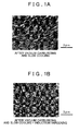
- FIG. 1A and 1B show scanning electron microscope (SEM) images of Example 1.
- Vacuum carburizing was performed with an acetylene gas so as to keep the temperature at 900 to 1,050°C under a reduced pressure of 1/100 atm or less. After the carburizing, air cooling was performed to transform the structure into a pearlite single phase.
- Heating was performed at a temperature of 750 to 850°C for 20 to 30 seconds, and then, cooling (more specifically, water cooling in these examples) was performed at a cooling rate of 10°C/s or higher.
- test gears were rotated under load to evaluate such a tooth root stress that breaks the tooth roots when the test gears were rotated 10 7 times, and this tooth root stress was used as a measure of the tooth root fatigue strength.
- the tooth roots of other sample gears were strengthened by shot peening, and these sample gears were similarly rotated under load to evaluate such a tooth surface stress that breaks the tooth surfaces when the sample gears were rotated 10 7 times, and this tooth surface stress was used as a measure of the tooth surface fatigue strength.
- the surface of the gear end face (the middle part of the tooth surface) was directly measured by spark discharge optical emission spectrometry (JIS G 1253).
- the surface layer portions of the carburized parts were mirror polished, and were corroded with a picric acid alcohol solution, and then, carbides in an area of 0.1 mm 2 were observed by an SEM (scanning electron microscope) at 10,000 times magnification to obtain the ratio of the total area of carbides having a size of 1 ⁇ m or less in cross section, to the total carbide area.
- the tooth surface fatigue strength is low both in Comparative Example 3 in which the surface carbon concentration is as low as 0.70, and no carbide is produced on the surface, and in Comparative Example 4 in which the surface carbon concentration is as low as 0.85, and the amount of fine carbides on the surface is as low as 28%. Moreover, the tooth surface fatigue strength is low in Comparative Example 5 in which the heating temperature for induction hardening is as low as 710°C, and the amount of fine carbides on the surface is as low as 42%. Moreover, the tooth surface fatigue strength is low in Comparative Example 6 in which the heating temperature for induction hardening is as high as 910°C, and no carbide is produced on the surface.
- FIG. 1A is an SEM image of Example 1 after vacuum carburizing and slow cooling
- FIG. 1B is an SEM image after the subsequent induction hardening (both are at 10,000 times magnification).
- FIG. 1A It can be seen from FIG. 1A that the structure has transformed into a pearlite single phase structure in a desirable manner after the vacuum carburizing and the slow cooling. It can also be seen from FIG. 1B that a multiplicity of fine carbides, resulting from dividing cementite, have been finely dispersed by the subsequent induction hardening (grain-like white dots in FIG. 1B are carbides).
Landscapes
- Chemical & Material Sciences (AREA)
- Engineering & Computer Science (AREA)
- Materials Engineering (AREA)
- Mechanical Engineering (AREA)
- Metallurgy (AREA)
- Organic Chemistry (AREA)
- Chemical Kinetics & Catalysis (AREA)
- Physics & Mathematics (AREA)
- Thermal Sciences (AREA)
- Crystallography & Structural Chemistry (AREA)
- Heat Treatment Of Articles (AREA)
- Solid-Phase Diffusion Into Metallic Material Surfaces (AREA)
Abstract

This steel is vacuum carburized so that a surface carbon concentration falls in a range of 0.9 to 1.5%, and then, is air-cooled to transform a surface structure into pearlite, and thereafter, cementite is divided by induction hardening, thereby producing fine carbides containing 90% or more of carbides of 1 µm or more.
Description
- The present invention relates to methods for manufacturing a carburized part, and steel parts.
- Conventionally, for mechanical parts such as gears, which are required to have high surface hardness, JIS (Japanese Industrial Standards) steels such as SCR420 are used by processing the steel into a shape of a part, and then performing surface hardening through case hardening.
At this time, the surface hardness and the strength can be increased if fine carbides can be produced on the surface, and also a large amount of carbides can be produced by the case hardening. - Actually, however, conventional case hardening methods cannot produce a large amount of such fine carbides on the surface in a desirable manner, and cannot increase the surface strength sufficiently:
- Conventionally, a method for performing induction hardening after carburizing is known as a case hardening method. This method can be said to be an excellent method capable of providing both advantages of carburizing and advantages of induction hardening.
In the case where case hardening is performed by a common method in which direct quenching is performed after carburizing, martensite is formed up to the inside of the part, whereby the residual strain is increased. However, the strain is small in the case where induction hardening is performed after carburizing. This advantage is obtained because the induction hardening is capable of hardening only the surface without changing the inner structure of the part. - However, SCR420, which is a steel for carburizing, has a high content of Cr that tends to form carbides. Thus, when SCR420 is used, carbides tend to be produced during the carburizing process, and these carbides are less likely to melt in the subsequent induction hardening process. Therefore, it is difficult to obtain a carburized part with a uniform surface structure.
Moreover, fracture, starting from the residual carbides on the surface, tends to occur, whereby the strength is reduced. - In conventional common gas carburizing, the hardness has a highest value at a surface carbon concentration of about 0.8%, and it is difficult to increase the surface carbon concentration to a value higher than about 0.8%.
On the other hand, the surface carbon concentration can be increased to a value higher than about 0.8% in the case where vacuum carburizing is performed as a carburizing technique.
However, since SCR420 has a high content of Cr that tends to form carbides, increasing the surface carbon concentration by vacuum carburizing tends to further produce Cr carbides, and these Cr carbides become coarse. Such Cr carbides do not melt in the subsequent induction hardening process, whereby fracture, starting from the carbides, is further facilitated, reducing the strength.
In view of the above problems, the surface carbon concentration in carburizing is conventionally reduced to prevent production of carbides. In this case, however, the surface hardness is insufficient, and thus, a sufficient strength is not obtained. - Note that a carburized part using a steel having a composition similar to that of the present invention is disclosed in
Patent Document 1 shown below as a related art of the present invention.
However, the carburized part disclosed inPatent Document 1 is completely different from the present invention in a hardening technique following a carburizing process, and in a technique of producing carbides on the surface of the carburized part. Thus, the carburized part ofPatent Document 1 is different from the present invention. - Moreover,
Patent Document 2 shown below describes that an induction hardening step is performed after a carbonitriding step in a manufacturing method of a track member. However, the method disclosed inPatent Documents 2 is completely different from the present invention in the composition of a steel material, and thus, is also different from the present invention in a technique of producing carbides. Thus, the method inPatent Document 2 is different from the present invention. -
- [Patent Document 1] Japanese Patent Application Publication No.
JP-A-2007-291486 - [Patent Document 2] Japanese Patent Application Publication No.
JP-A-2008-63603 - The present invention was developed in view of the above problems, and it is an object of the present invention to provide a manufacturing method of a carburized part, which is capable of producing a large amount of fine carbides on a surface by a case hardening process, and thus, capable of producing high hardness, high strength carburized parts, and to provide a steel part.
- Thus,
claim 1 relates to a manufacturing method of a carburized part, characterized by including: vacuum carburizing a steel under a reduced pressure of 2 kPa or less, so that a surface carbon concentration after slow cooling performed after carburizing falls in a range of 0.9 to 1.5%, where the steel has a composition containing, by mass percent, C: 0.15 to 0.25%, Si: 0.90 to 1.30%, Mn: 0.70 to 1.10%, P: 0.030% or less, S: 0.100% or less, Cu: 0.01 to 0.50%, Ni: 0.01 to 0.50%, Cr: 0.20 to 0.50%, Mo: 0.50% or less, Al: 0.30% or less, N: 0.05% or less, and a balance of Fe and unavoidable impurities, and satisfying the following Expression (1)
(where each element symbol in Expression (1) represents a content in mass percent of the element); performing the slow cooling by air cooling at such a cooling rate that causes pearlite transformation, to transform a surface structure into pearlite; and thereafter, performing induction hardening under such heating and cooling conditions that produce fine carbides in a range of up to 0.1 mm from a surface by finely dividing cementite in the pearlite structure, where the fine carbides contains 90% or more of carbides of 1 µm or less. - A method of
claim 2 is characterized in that, inclaim 1, the slow cooling by the air cooling is performed at a cooling rate of 5°C/s to 0.2°C/s, and the induction hardening is performed at a heating temperature of 750 to 850°C. - A method of
claim 3 is characterized in that, inclaim - A method of
claim 4 is characterized in that, in any one ofclaims 1 to 3, the vacuum carburizing is performed so that the surface carbon concentration after the slow cooling becomes 1.0% or more. -
Claim 5 relates to a steel part, characterized in that the steel part has a surface carbon concentration of 0.9 to 1.5%, and fine carbides have been produced in a range of up to 0.1 mm from a surface by dividing cementite in a pearlite structure, where the fine carbides contain 90% or more of carbides of 1 µm or less. - A steel part of
claim 6 is characterized in that, inclaim 5, the steel part has a composition containing, by mass percent, C: 0.15 to 0.25%, Si: 0.90 to 1.30%, Mn: 0.70 to 1.10%, P: 0.030% or less, S: 0.100% or less, Cu: 0.01 to 0.50%, Ni: 0.01 to 0.50%, Cr: 0.20 to 0.50%, Mo: 0.50% or less, Al: 0.30% or less, N: 0.05% or less, and a balance of Fe and unavoidable impurities, and satisfying the following Expression (1)
- A steel part of
claim 7 is characterized in that, inclaim - A steel part of
claim 8 is characterized in that, in any one ofclaims 5 to 7, the steel further contains, in mass percent, one or more of Nb: 0.02 to 0.20%, Ti: 0.02 to 0.20%, and B: 0.0005 to 0.0100%. - A steel part of claim 9 is characterized in that, in any one of
claims 5 to 8, the surface carbon concentration is 1.0% or more. - As described above, in a manufacturing method of a carburized part according to the present invention, a low-C steel material is processed in advance into a shape of a part such as a gear, and is subjected to vacuum carburizing and slow cooling, and then, to induction hardening to harden the surface, thereby producing a carburized part.
- In the present invention, C is introduced into the surface of a carburized part by the vacuum carburizing so that the surface carbon concentration after the slow cooling becomes 0.9 to 1.5%, and then, the surface structure is transformed to a pearlite single phase structure by the slow cooling.
- Then, lamellar cementite, extending in a thin, elongated form in the pearlite structure, is finely divided by induction hardening, and then, martensite transformation is caused by cooling, whereby hardening is performed. Thus, numbers of fine carbides are produced in a dispersed state in the surface (a surface layer).
In this manner, carbides on the surface of the carburized part are fine-grained as much as possible, and also, a large amount of such carbides is produced, whereby the surface hardness and the surface strength of the carburized part are increased as compared to conventional examples. - That is, the manufacturing method of the present invention is characterized in that carbides on the surface of the carburized part are finely precipitated by dividing the cementite in the pearlite structure.
The present invention also uses a vacuum carburizing technique as a carburizing method.
The highest surface carbon concentration that can be achieved by common gas carburizing is about 0.8%. However, in the present invention, a surface carbon concentration higher than about 0.8% can be achieved by using vacuum carburizing.
The "vacuum carburizing" as used herein generally refers to a carburizing method in which an ambient pressure in a furnace is reduced, and a hydrocarbon gas (such as, e.g., methane, propane, ethylene, or acetylene) is directly introduced into the furnace as a carburizing gas, and by active carbons, which are decomposed when the gas is brought into contact with the steel surface, carbides are produced and carbons are accumulated during a carburizing period in which carbons are supplied to the steel surface, and then, the carbides are decomposed and the accumulated carbides are dissolved in a matrix during a diffusion period, whereby carbons are diffused inward, and the steel is carburized. The carbon supply route is not limited to the route via carbides, but carbons may be supplied via direct dissolution. In the present invention, the carburizing method is performed at a reduced pressure of 2 kPa or less.
In this case, a large amount of fine carbides can be produced on the surface of the carburized part, which greatly contributes to an increase in hardness and strength of the surface of the carburized part. - It should be noted that steels such as conventional SCR420 have a high content of Cr that tends to form carbides. Thus, when such steel is used as a steel material, Cr forms carbides during a carburizing process, if a large amount of C is introduced into the surface by vacuum carburizing.
In this case, these carbides become large, round, coarse carbides. Such coarse carbides become foreign matter on the surface of the carburized part, and serves as a starting point of fracture, thereby reducing the surface strength. - Thus, in the present invention, the steel material contains a low content of Cr that tends to form carbides, and a high content of Si that hinders production of carbides. In this manner, the composition of the steel material is adjusted so that, even if no carbide is formed during vacuum carburizing and C is introduced at a high concentration into the surface by the vacuum carburizing, the structure transforms into a pearlite single phase structure by the subsequent slow cooling process.
- In the present invention, it is desirable that the cooling rate after carburizing be in the range of 5°C/s to 0.2°C/s, in order to transform the structure into a pearlite single phase structure by the slow cooling, which is performed after the surface is carburized with a high concentration of C by the vacuum carburizing.
If the cooling rate is lower than 0.2°C/s, coarse carbides are produced at the grain boundaries, whereby higher surface hardness and higher strength, which is an object of the present invention, cannot be implemented desirably.
On the other hand, if the cooling rate is higher than 5°C/s, the steel material is hardened by the cooling performed after the carburizing, whereby the structure transforms into martensite. - After such a carburizing process, the surface of the carburized part is induction hardened in the present invention.
Performing such high frequency heating for a short time (the heating time is 20 to 30 seconds) finely divides cementite in the pearlite structure in a longitudinal direction into fine carbides. - In this induction hardening, it is desirable that the surface of the carburized part be heated in the temperature range of 750 to 850°C.
If the temperature is higher than 850°C, not only the cementite is divided, but also the carbides produced by dividing the cementite dissolve into a matrix, whereby the object of the present invention cannot be achieved desirably.
On the other hand, if the temperature is lower than 750°C, the structure does not transform into austenite by the high frequency heating, and thus, is not sufficiently hardened by the subsequent cooling. That is, the structure does not transform into martensite in a desirable manner. - That is, although heating at a high temperature of 1,150°C or higher is performed in common induction hardening, it is preferable to perform heating at a low temperature of 750 to 850°C in the present invention.
Note that, in the induction hardening, it is desirable to perform cooling at 10°C/s or higher, and preferably, to perform water cooling. - In the manufacturing method of the present invention described above, a large amount of carbides can be produced on the surface of the carburized part, as shown by the values of the surface carbon concentration in the table of the examples described below (the values of the surface carbon concentration in the examples directly represent the amount of carbons). Moreover, fine carbides, containing 90% (the area ratio) or more of carbides having a size of 1 µm or less, can be produced.
- Note that, in the present invention, since the steel material is a soft, low-C steel material, it is not necessary to perform spheroidizing before processing the steel material into a part such as a gear. Thus, no large, round carbide is produced by the spheroidizing.
- In the present invention, the steel may contain one or more of Nb, Ti, and B in the above ranges.
Moreover, in the vacuum carburizing, carburizing may be performed so that the surface carbon concentration after slow cooling becomes 1.0% or more. -
Claims 5 through 9 relate to a steel part, where the surface hardness and the strength of the steel part can be increased as compared to conventional examples, since a large amount of fine carbides is produced on the surface of the steel part. - The reason why the chemical components of the steel material in the present invention are limited to the above ranges will be described below in detail.
C: 0.15 to 0.25%
If the C content is lower than the lower limit, ferrite is produced in the core, whereby the strength is reduced. On the other hand, if the C content exceeds the upper limit of 0.25%, workability, especially machinability, is reduced.
If the C content exceeds a certain value, the steel becomes hard, whereby spheroidizing is required in some cases when processing the workpiece into a part such as a gear. In such a case, large round carbides are produced during the spheroidizing process. - Si: 0.90 to 1.30%
In the present invention, Si is an important component for transforming the structure into pearlite by cooling after vacuum carburizing. If the Si content is lower than 0.90%, carbides tend to be produced by air-cooling after vacuum carburizing. Moreover, hardenability is reduced, whereby the strength is reduced.
On the other hand, if a large amount of Si exceeding 1.30% is contained, workability, especially machinability, is reduced.
Si is an element that facilitates grain boundary oxidation in the case of common gas carburizing, and this grain boundary oxidized layer causes reduction in impact strength and fatigue strength of the tooth root. It should be noted that, in the present invention, the use of vacuum carburizing (an ambient pressure is 2 kPa or less, for example) effectively reduces the problem of grain boundary oxidation, even though Si is contained.
In the present invention, a more desirable range of Si is 1.00 to 1.30%. - Mn: 0.70 to 1.10%
Mn is added as a deoxidizer when melting steel. If a large amount of Mn exceeding 1.10% is contained, workability, especially machinability, is reduced.
On the other hand, if the Mn content is less than 0.70%, ferrite is produced in the core, whereby the strength is reduced. - P: 0.030% or less
S: 0.100% or less
These are impurities, and are components that are not preferable for mechanical properties of the carburized part. The P content and the S content are limited to the above respective upper limits or less.
In particular, when toughness and hot workability are required, a more desirable range of S is 0.030% or less. - Cu: 0.01 to 0.50%
Ni: 0.01 to 0.50%
Cu and Ni are components that suppress production of carbides, and the Cu content and the Ni content are at least the lower limit of 0.01 %.
On the other hand, adding a large amount of Cu and Ni exceeding 0.50% reduces hot workability.
A more desirable range of Cu is 0.05 to 0.30%, and a more desirable range of Ni is 0.04 to 0.30%. The Cu content of 0.05% or more and the Ni content of 0.04% or more can improve the core strength. - Cr: 0.20 to 0.50%
Cr is a component that facilitates production of carbides. If a large amount of Cr exceeding 0.50% is added, Cr forms carbides during processing after carburizing. Moreover, a pearlite single phase structure intended by the present invention cannot be obtained. Adding a large amount of Cr also reduces workability, in particular, machinability.
On the other hand, the Cr content less than 0.20% reduces hardenability, whereby the strength is reduced.
A more desirable range of Cr is 0.20 to 0.40%. The Cr content of 0.25% or higher can improve the core strength. - Mo: 0.50% or less
Mo is a component that improves hardenability. Adding a large amount of Mo exceeding 0.50% reduces workability of a steel, in particular, machinability thereof.
Note that, if the amount of Mo is less than 0.01%, martensitic transformation during hardening is not sufficient. This causes incomplete hardening, whereby the strength is reduced. Thus, it is desirable to add at least 0.01 % or more of Mo.
A more desirable range of Mo is 0.05 to 0.40%. Moreover, the Mo content less than 0.30% can suppress production of carbides. - Al: 0.30% or less
Al is added as a deoxidizer. Al has also a function to refine crystal grains to increase the strength.
However, adding a large amount of Al exceeding 0.30% reduces the strength, since alumina is formed in a steel.
Note that, in order to ensure the function to make crystal grains finer to increase the strength, it is desirable to add 0.01 % or more of Al.
A more desirable range of Al is 0.01 to 0.04%. - N: 0.05% or less
N has a function to prevent coarsening of crystal grains. Since this effect is saturated at about 0.05% ofN, the range ofN is about 0.05% or less.
Note that it is desirable that the N content be 0.002% or more. Further reduction in the N content increases the cost.
A more desirable range of N is 0.01 to 0.03%. -

Si, Ni, and Cu suppress production of carbides, while Cr increases production of carbides.
In the present invention, by balancing the respective amounts of Si, Ni, Cu, and Cr, a pearlite structure single phase can be produced by cooling after vacuum carburizing, even if a workpiece is carburized at a high concentration by the vacuum carburization. - Surface carbon concentration: 0.9 to 1.5% (mass percent)
The strength of the surface of a carburized part cannot be effectively increased if the amount of carbides is less than 0.9%. On the other hand, even if the surface carbon concentration exceeds 1.5%, the strength is no longer increased, while graphite adheres and a carburizing furnace is polluted during carburizing. Thus, the upper limit is 1.5%. - Cooling rate after vacuum carburizing: 5°C/s to 0.2°C/s
If the cooling rate is higher than the upper limit, the structure transforms into martensite, and does not transform into pearlite. On the other hand, if the cooling rate is lower than the lower limit, coarse carbides are precipitated at the grain boundaries.
A more desirable range of the cooling rate is 4°C/s to 0.4°C/s. - Induction hardening temperature: 750 to 850°C
If the hardening temperature is lower than the lower limit, the structure does not transform into austenite. This results in defective hardening, whereby the strength is reduced.
On the other hand, if the upper limit is higher than the upper limit, carbides melt too much that no carbide remains on the surface of a carburized part. - [
FIG. 1] FIG. 1A and 1B show scanning electron microscope (SEM) images of Example 1. - An embodiment of the present invention will be described in detail below.
Steels for carburizing having chemical compositions shown in Table 1 were melted, and each material was machined into a shape of a test gear described below.
The resultant parts were vacuum carburized at a temperature of 900 to 1,050°C, and more specifically, at a temperature shown in Table 2, and then, were cooled at a cooling rate of 5°C/s to 0.2°C/s, and more specifically, at a cooling rate shown in Table 2, and then, were further cooled under the heating conditions shown in Table 2 and the cooling conditions of 10°C/s or higher to perform induction hardening.
As described below, a fatigue strength test was performed on the obtained carburized parts to evaluate the tooth surface fatigue strength and the tooth root fatigue strength.
The evaluation result is also shown in Table 2. - Module: 2.5
Number of Teeth: 30
Pitch Circle Diameter: 82.753 mm
Face Width: 20 mm
Torsion Angle: 25 degrees - Vacuum carburizing was performed with an acetylene gas so as to keep the temperature at 900 to 1,050°C under a reduced pressure of 1/100 atm or less.
After the carburizing, air cooling was performed to transform the structure into a pearlite single phase. - Heating was performed at a temperature of 750 to 850°C for 20 to 30 seconds, and then, cooling (more specifically, water cooling in these examples) was performed at a cooling rate of 10°C/s or higher.
- The test gears were rotated under load to evaluate such a tooth root stress that breaks the tooth roots when the test gears were rotated 107 times, and this tooth root stress was used as a measure of the tooth root fatigue strength. The tooth roots of other sample gears were strengthened by shot peening, and these sample gears were similarly rotated under load to evaluate such a tooth surface stress that breaks the tooth surfaces when the sample gears were rotated 107 times, and this tooth surface stress was used as a measure of the tooth surface fatigue strength.
- The surface of the gear end face (the middle part of the tooth surface) was directly measured by spark discharge optical emission spectrometry (JIS G 1253).
- After the induction hardening, the surface layer portions of the carburized parts were mirror polished, and were corroded with a picric acid alcohol solution, and then, carbides in an area of 0.1 mm2 were observed by an SEM (scanning electron microscope) at 10,000 times magnification to obtain the ratio of the total area of carbides having a size of 1 µm or less in cross section, to the total carbide area.
- [Table 1]
- [Table 2]
- As shown by the result of Table 2, in Comparative Example 1 in which the Si content is as low as 0.71 %, and the value of Expression (1) is 0.28, which is lower than the lower limit of the present invention, the proportion of carbides of 1 µm or less is as low as 8%, resulting in a low tooth root fatigue strength.
- In Comparative Example 2 in which the Cr content is 0.80%, which is higher than the upper limit of 0.50% in the present invention, and the value of Expression (1) is lower than the lower limit of 0.5 in the present invention, the proportion of fine (1 µm or less) carbides is as low as 61 %, and thus, both the tooth surface fatigue strength and the tooth root fatigue strength are low.
- The tooth surface fatigue strength is low both in Comparative Example 3 in which the surface carbon concentration is as low as 0.70, and no carbide is produced on the surface, and in Comparative Example 4 in which the surface carbon concentration is as low as 0.85, and the amount of fine carbides on the surface is as low as 28%.
Moreover, the tooth surface fatigue strength is low in Comparative Example 5 in which the heating temperature for induction hardening is as low as 710°C, and the amount of fine carbides on the surface is as low as 42%.
Moreover, the tooth surface fatigue strength is low in Comparative Example 6 in which the heating temperature for induction hardening is as high as 910°C, and no carbide is produced on the surface. - On the other hand, the examples of the present invention have excellent results since a large amount of fine carbides is produced on the surface, and both the tooth surface fatigue strength and the tooth root fatigue strength are high.
Note thatFIG. 1A is an SEM image of Example 1 after vacuum carburizing and slow cooling, andFIG. 1B is an SEM image after the subsequent induction hardening (both are at 10,000 times magnification). - It can be seen from
FIG. 1A that the structure has transformed into a pearlite single phase structure in a desirable manner after the vacuum carburizing and the slow cooling. It can also be seen fromFIG. 1B that a multiplicity of fine carbides, resulting from dividing cementite, have been finely dispersed by the subsequent induction hardening (grain-like white dots inFIG. 1B are carbides). - Although the embodiment of the present invention has been described in detail, this embodiment was shown by way of example only, and the present invention can be implemented in various modified forms without departing from the subject matter of the present invention.
Claims (9)
- A method for manufacturing a carburized part, characterized by comprising:vacuum carburizing a steel under a reduced pressure of 2 kPa or less, so that a surface carbon concentration after slow cooling performed after carburizing falls in a range of 0.9 to 1.5%, where the steel has a composition containing, by mass percent,
C: 0.15 to 0.25%,
Si: 0.90 to 1.30%,
Mn: 0.70 to 1.10%,
P: 0.030% or less,
S: 0.100% or less,
Cu: 0.01 to 0.50%,
Ni: 0.01 to 0.50%,
Cr: 0.20 to 0.50%,
Mo: 0.50% or less,
Al: 0.30% or less,
N: 0.05% or less, and
a balance of Fe and unavoidable impurities, and satisfying following Expression (1)
(where each element symbol in Expression (1) represents a content in mass percent of the element);performing the slow cooling by air cooling at such a cooling rate that causes pearlite transformation, to transform a surface structure into pearlite; andthereafter, performing induction hardening under such heating and cooling conditions that produce fine carbides in a range of up to 0.1 mm from a surface by finely dividing cementite in the pearlite structure, where the fine carbides contain 90% or more of carbides of 1 µm or less. - The method according to claim 1, characterized in that the slow cooling by air cooling is performed at a cooling rate of 5°C/s to 0.2°C/s, and the induction hardening is performed at a heating temperature of 750 to 850°C.
- The method according to claim 1 or 2, characterized in that the steel further contains, in mass percent, one or more of
Nb: 0.02 to 0.20%,
Ti: 0.02 to 0.20%, and
B: 0.0005 to 0.0100%. - The method according to any one of claims 1 to 3, characterized in that the vacuum carburizing is performed so that the surface carbon concentration after the slow cooling becomes 1.0% or more.
- A steel part, characterized in that the steel part has a surface carbon concentration of 0.9 to 1.5%, and fine carbides have been produced in a range of up to 0.1 mm from a surface by dividing cementite in a pearlite structure, where the fine carbides contain 90% or more of carbides of 1 µm or less.
- The steel part according to claim 5, characterized in that the steel part has a composition containing, by mass percent,
C: 0.15 to 0.25%,
Si: 0.90 to 1.30%,
Mn: 0.70 to 1.10%,
P: 0.030% or less,
S: 0.100% or less,
Cu: 0.01 to 0.50%,
Ni: 0.01 to 0.50%,
Cr: 0.20 to 0.50%,
Mo: 0.50% or less,
Al: 0.30% or less,
N: 0.05% or less, and
a balance of Fe and unavoidable impurities, and satisfying the following Expression (1)
(where each element symbol in Expression (1) represents a content in mass percent of the element), and
the fine carbides have been produced in the range of up to 0.1 mm from the surface by performing vacuum carburizing and subsequent cooling, and induction hardening. - The steel part according to claim 5 or 6, characterized in that the carbides have been produced in a structure having, in area percent, 50% or more of a martensite structure.
- The steel part according to any one of claims 5 to 7, characterized in that the steel further contains, in mass percent, one or more of
Nb: 0.02 to 0.20%,
Ti: 0.02 to 0.20%, and
B: 0.0005 to 0.0100%. - The steel part according to any one of claims 5 to 8, characterized in that the surface carbon concentration is 1.0% or more.
Applications Claiming Priority (2)
| Application Number | Priority Date | Filing Date | Title |
|---|---|---|---|
| JP2008261673A JP5305820B2 (en) | 2008-10-08 | 2008-10-08 | Manufacturing method of carburized parts and steel parts |
| PCT/JP2009/066693 WO2010041561A1 (en) | 2008-10-08 | 2009-09-25 | Process for production of carburized part and steel part |
Publications (3)
| Publication Number | Publication Date |
|---|---|
| EP2284287A1 true EP2284287A1 (en) | 2011-02-16 |
| EP2284287A4 EP2284287A4 (en) | 2015-05-20 |
| EP2284287B1 EP2284287B1 (en) | 2022-01-12 |
Family
ID=42074847
Family Applications (1)
| Application Number | Title | Priority Date | Filing Date |
|---|---|---|---|
| EP09819096.0A Active EP2284287B1 (en) | 2008-10-08 | 2009-09-25 | Method for manufacturing a carburized part and steel part |
Country Status (6)
| Country | Link |
|---|---|
| US (1) | US8123873B2 (en) |
| EP (1) | EP2284287B1 (en) |
| JP (1) | JP5305820B2 (en) |
| KR (1) | KR101244134B1 (en) |
| CN (1) | CN102066586B (en) |
| WO (1) | WO2010041561A1 (en) |
Cited By (2)
| Publication number | Priority date | Publication date | Assignee | Title |
|---|---|---|---|---|
| US9212416B2 (en) | 2009-08-07 | 2015-12-15 | Swagelok Company | Low temperature carburization under soft vacuum |
| US9617632B2 (en) | 2012-01-20 | 2017-04-11 | Swagelok Company | Concurrent flow of activating gas in low temperature carburization |
Families Citing this family (15)
| Publication number | Priority date | Publication date | Assignee | Title |
|---|---|---|---|---|
| US8733199B2 (en) | 2010-04-01 | 2014-05-27 | Aisin Aw Co., Ltd. | Gears and its process of manufacture |
| JP6205854B2 (en) * | 2013-03-26 | 2017-10-04 | 大同特殊鋼株式会社 | Vacuum carburizing method |
| JP6337580B2 (en) * | 2013-06-26 | 2018-06-06 | 大同特殊鋼株式会社 | Carburized parts |
| CN103343213A (en) * | 2013-07-15 | 2013-10-09 | 南京金鑫传动设备有限公司 | Heat treatment method for thin-walled gear ring |
| WO2016073814A1 (en) * | 2014-11-06 | 2016-05-12 | The Johns Hopkins University | Method for forming binder-free refractory carbide, nitride and boride coatings with a controlled porosity |
| US10774413B2 (en) | 2015-11-11 | 2020-09-15 | Honeywell International Inc. | Low pressure induction carburization |
| BR112018009373A8 (en) * | 2016-01-26 | 2019-02-26 | Sintokogio Ltd | cast steel projection material |
| RU2667948C1 (en) * | 2017-04-20 | 2018-09-25 | Федеральное государственное бюджетное образовательное учреждение высшего образования "Ульяновский государственный аграрный университет имени П.А. Столыпина" | Low-carbon steel parts surface electromechanical processing method |
| JP6922759B2 (en) * | 2018-01-25 | 2021-08-18 | トヨタ自動車株式会社 | Manufacturing method of steel parts |
| JP7270343B2 (en) | 2018-06-18 | 2023-05-10 | 株式会社小松製作所 | Method for manufacturing mechanical parts |
| JP7257351B2 (en) * | 2020-03-17 | 2023-04-13 | 愛知製鋼株式会社 | Crude material for vacuum carburizing and its manufacturing method |
| JP7866168B2 (en) * | 2021-12-28 | 2026-05-27 | 日本製鉄株式会社 | Steel and carburized/hardened parts |
| CN116695000B (en) * | 2023-06-28 | 2026-07-17 | 鞍钢股份有限公司 | Superfine pearlite steel rail for heavy-duty railway and production method thereof |
| CN117327989B (en) * | 2023-09-06 | 2025-12-26 | 江阴兴澄特种钢铁有限公司 | A multi-purpose automotive transmission gear steel and its manufacturing method |
| CN117089802B (en) * | 2023-09-18 | 2025-08-19 | 中天钢铁集团有限公司 | Heat treatment process for measuring decarburized layer of water-passing bearing steel |
Family Cites Families (16)
| Publication number | Priority date | Publication date | Assignee | Title |
|---|---|---|---|---|
| US247901A (en) * | 1881-10-04 | garrison | ||
| JP2579640B2 (en) | 1987-07-30 | 1997-02-05 | 新日本製鐵株式会社 | Manufacturing method of high fatigue strength case hardened product |
| JPH05255733A (en) | 1992-03-10 | 1993-10-05 | Sumitomo Metal Ind Ltd | Method for producing delayed fracture resistant carburized case hardened steel |
| JP3436459B2 (en) | 1996-06-27 | 2003-08-11 | アイシン精機株式会社 | Heat treatment method for steel |
| JPH10147814A (en) * | 1996-11-20 | 1998-06-02 | Kobe Steel Ltd | Manufacturing method of case hardened steel products with less heat treatment distortion |
| JP3894635B2 (en) * | 1997-08-11 | 2007-03-22 | 株式会社小松製作所 | Carburized member, manufacturing method thereof, and carburizing system |
| JP4354277B2 (en) * | 2001-12-25 | 2009-10-28 | アイシン・エィ・ダブリュ株式会社 | Method for manufacturing carburized and quenched members |
| JP2004076125A (en) * | 2002-08-21 | 2004-03-11 | Komatsu Ltd | Rolling member |
| JP5358875B2 (en) * | 2005-04-28 | 2013-12-04 | アイシン・エィ・ダブリュ株式会社 | Steel member cooling method |
| EP1876256B1 (en) | 2005-04-28 | 2012-01-18 | Aisin AW Co., Ltd. | Carburized induction-hardened component |
| US8580050B2 (en) | 2005-08-24 | 2013-11-12 | Daido Steel Co., Ltd. | Carburized machine parts |
| JP4254816B2 (en) * | 2005-08-24 | 2009-04-15 | 大同特殊鋼株式会社 | Carburized parts |
| CN101233247B (en) | 2005-09-26 | 2011-07-06 | 爱信艾达株式会社 | Steel members, method for heat treatment of the same, and process for production thereof |
| JP2008063603A (en) | 2006-09-05 | 2008-03-21 | Ntn Corp | Method for manufacturing track member, method for manufacturing valve device, and track member |
| JP2008195997A (en) * | 2007-02-09 | 2008-08-28 | Daido Steel Co Ltd | Low strained carburizing gas quenching steel and low strain carburized parts made from it |
| JP5018586B2 (en) | 2007-04-09 | 2012-09-05 | 大同特殊鋼株式会社 | High strength carburizing induction hardening parts |
-
2008
- 2008-10-08 JP JP2008261673A patent/JP5305820B2/en active Active
-
2009
- 2009-09-18 US US12/585,608 patent/US8123873B2/en active Active
- 2009-09-25 WO PCT/JP2009/066693 patent/WO2010041561A1/en not_active Ceased
- 2009-09-25 KR KR1020107028030A patent/KR101244134B1/en not_active Expired - Fee Related
- 2009-09-25 CN CN2009801223733A patent/CN102066586B/en active Active
- 2009-09-25 EP EP09819096.0A patent/EP2284287B1/en active Active
Non-Patent Citations (1)
| Title |
|---|
| See references of WO2010041561A1 * |
Cited By (6)
| Publication number | Priority date | Publication date | Assignee | Title |
|---|---|---|---|---|
| US9212416B2 (en) | 2009-08-07 | 2015-12-15 | Swagelok Company | Low temperature carburization under soft vacuum |
| US10156006B2 (en) | 2009-08-07 | 2018-12-18 | Swagelok Company | Low temperature carburization under soft vacuum |
| US10934611B2 (en) | 2009-08-07 | 2021-03-02 | Swagelok Company | Low temperature carburization under soft vacuum |
| US9617632B2 (en) | 2012-01-20 | 2017-04-11 | Swagelok Company | Concurrent flow of activating gas in low temperature carburization |
| US10246766B2 (en) | 2012-01-20 | 2019-04-02 | Swagelok Company | Concurrent flow of activating gas in low temperature carburization |
| US11035032B2 (en) | 2012-01-20 | 2021-06-15 | Swagelok Company | Concurrent flow of activating gas in low temperature carburization |
Also Published As
| Publication number | Publication date |
|---|---|
| JP2010090437A (en) | 2010-04-22 |
| EP2284287B1 (en) | 2022-01-12 |
| KR20110018899A (en) | 2011-02-24 |
| US20100084051A1 (en) | 2010-04-08 |
| US8123873B2 (en) | 2012-02-28 |
| JP5305820B2 (en) | 2013-10-02 |
| KR101244134B1 (en) | 2013-03-14 |
| CN102066586B (en) | 2013-01-16 |
| WO2010041561A1 (en) | 2010-04-15 |
| CN102066586A (en) | 2011-05-18 |
| EP2284287A4 (en) | 2015-05-20 |
Similar Documents
| Publication | Publication Date | Title |
|---|---|---|
| EP2284287B1 (en) | Method for manufacturing a carburized part and steel part | |
| CN104204263B (en) | Steel wire rod or bar steel with excellent cold forgeability | |
| KR100851083B1 (en) | Steel and steel wire for high strength spring | |
| KR101745224B1 (en) | Steel for carburizing | |
| EP2562283B1 (en) | Steel part having excellent in temper softening resistance | |
| KR100968938B1 (en) | High strength spring steel and heat treated steel wire for high strength spring | |
| JP5558887B2 (en) | Manufacturing method of high strength parts using Ti and B added steels with excellent low cycle fatigue strength | |
| CN101321884A (en) | Heat-treated steel for high-strength spring | |
| CN102131945A (en) | Case hardening steel, carburized component, and method for producing case hardening steel | |
| KR102402361B1 (en) | Steel for parts subjected to carburizing treatment | |
| JP2019218582A (en) | Mechanical component | |
| EP1847631A1 (en) | Carburized component and manufacturing method thereof | |
| JP2018199838A (en) | Carburized part | |
| JP5599211B2 (en) | Manufacturing method of bearing parts and bearing parts | |
| EP3115477B1 (en) | Age hardening non-heat treated bainitic steel | |
| JP4478072B2 (en) | High strength spring steel | |
| JPH10306343A (en) | Soft nitriding steel with excellent cold forgeability and pitting resistance | |
| JP2006161141A (en) | Carburized parts and manufacturing method thereof | |
| JPWO2020138432A1 (en) | Steel material | |
| JP2003231943A (en) | Case hardened steel with excellent temper softening resistance | |
| JP2018199837A (en) | Carburized parts | |
| JP7275665B2 (en) | Steel for carbo-nitriding | |
| JP7063071B2 (en) | Carburized parts | |
| CN114929916A (en) | Blank for vacuum carburization and method for producing same | |
| JP2021147643A (en) | Rough shape material for vacuum carburization and method for producing the same |
Legal Events
| Date | Code | Title | Description |
|---|---|---|---|
| PUAI | Public reference made under article 153(3) epc to a published international application that has entered the european phase |
Free format text: ORIGINAL CODE: 0009012 |
|
| 17P | Request for examination filed |
Effective date: 20101110 |
|
| AK | Designated contracting states |
Kind code of ref document: A1 Designated state(s): AT BE BG CH CY CZ DE DK EE ES FI FR GB GR HR HU IE IS IT LI LT LU LV MC MK MT NL NO PL PT RO SE SI SK SM TR |
|
| AX | Request for extension of the european patent |
Extension state: AL BA RS |
|
| DAX | Request for extension of the european patent (deleted) | ||
| RA4 | Supplementary search report drawn up and despatched (corrected) |
Effective date: 20150416 |
|
| RIC1 | Information provided on ipc code assigned before grant |
Ipc: C23C 8/22 20060101ALI20150410BHEP Ipc: C21D 9/32 20060101AFI20150410BHEP Ipc: C22C 38/06 20060101ALI20150410BHEP Ipc: C21D 1/06 20060101ALI20150410BHEP Ipc: C22C 38/04 20060101ALI20150410BHEP Ipc: C22C 38/42 20060101ALI20150410BHEP Ipc: C22C 38/60 20060101ALI20150410BHEP Ipc: C23C 8/80 20060101ALI20150410BHEP Ipc: C22C 38/44 20060101ALI20150410BHEP Ipc: C21D 1/10 20060101ALI20150410BHEP Ipc: C22C 38/02 20060101ALI20150410BHEP Ipc: C21D 9/46 20060101ALI20150410BHEP Ipc: C22C 38/00 20060101ALI20150410BHEP |
|
| 17Q | First examination report despatched |
Effective date: 20160317 |
|
| STAA | Information on the status of an ep patent application or granted ep patent |
Free format text: STATUS: EXAMINATION IS IN PROGRESS |
|
| REG | Reference to a national code |
Ref country code: DE Ref legal event code: R079 Ref document number: 602009064259 Country of ref document: DE Free format text: PREVIOUS MAIN CLASS: C21D0009320000 Ipc: C23C0008220000 |
|
| GRAP | Despatch of communication of intention to grant a patent |
Free format text: ORIGINAL CODE: EPIDOSNIGR1 |
|
| STAA | Information on the status of an ep patent application or granted ep patent |
Free format text: STATUS: GRANT OF PATENT IS INTENDED |
|
| RIC1 | Information provided on ipc code assigned before grant |
Ipc: C22C 38/60 20060101ALI20210825BHEP Ipc: C22C 38/44 20060101ALI20210825BHEP Ipc: C22C 38/42 20060101ALI20210825BHEP Ipc: C22C 38/06 20060101ALI20210825BHEP Ipc: C22C 38/04 20060101ALI20210825BHEP Ipc: C22C 38/02 20060101ALI20210825BHEP Ipc: C22C 38/00 20060101ALI20210825BHEP Ipc: C21D 9/46 20060101ALI20210825BHEP Ipc: C21D 9/32 20060101ALI20210825BHEP Ipc: C21D 1/42 20060101ALI20210825BHEP Ipc: C21D 1/10 20060101ALI20210825BHEP Ipc: C21D 1/06 20060101ALI20210825BHEP Ipc: C23C 8/80 20060101ALI20210825BHEP Ipc: C23C 8/22 20060101AFI20210825BHEP |
|
| INTG | Intention to grant announced |
Effective date: 20210910 |
|
| GRAS | Grant fee paid |
Free format text: ORIGINAL CODE: EPIDOSNIGR3 |
|
| GRAA | (expected) grant |
Free format text: ORIGINAL CODE: 0009210 |
|
| STAA | Information on the status of an ep patent application or granted ep patent |
Free format text: STATUS: THE PATENT HAS BEEN GRANTED |
|
| AK | Designated contracting states |
Kind code of ref document: B1 Designated state(s): AT BE BG CH CY CZ DE DK EE ES FI FR GB GR HR HU IE IS IT LI LT LU LV MC MK MT NL NO PL PT RO SE SI SK SM TR |
|
| REG | Reference to a national code |
Ref country code: GB Ref legal event code: FG4D |
|
| REG | Reference to a national code |
Ref country code: CH Ref legal event code: EP |
|
| REG | Reference to a national code |
Ref country code: IE Ref legal event code: FG4D |
|
| REG | Reference to a national code |
Ref country code: DE Ref legal event code: R096 Ref document number: 602009064259 Country of ref document: DE |
|
| REG | Reference to a national code |
Ref country code: AT Ref legal event code: REF Ref document number: 1462434 Country of ref document: AT Kind code of ref document: T Effective date: 20220215 |
|
| REG | Reference to a national code |
Ref country code: LT Ref legal event code: MG9D |
|
| REG | Reference to a national code |
Ref country code: NL Ref legal event code: MP Effective date: 20220112 |
|
| REG | Reference to a national code |
Ref country code: AT Ref legal event code: MK05 Ref document number: 1462434 Country of ref document: AT Kind code of ref document: T Effective date: 20220112 |
|
| PG25 | Lapsed in a contracting state [announced via postgrant information from national office to epo] |
Ref country code: NL Free format text: LAPSE BECAUSE OF FAILURE TO SUBMIT A TRANSLATION OF THE DESCRIPTION OR TO PAY THE FEE WITHIN THE PRESCRIBED TIME-LIMIT Effective date: 20220112 |
|
| PG25 | Lapsed in a contracting state [announced via postgrant information from national office to epo] |
Ref country code: SE Free format text: LAPSE BECAUSE OF FAILURE TO SUBMIT A TRANSLATION OF THE DESCRIPTION OR TO PAY THE FEE WITHIN THE PRESCRIBED TIME-LIMIT Effective date: 20220112 Ref country code: PT Free format text: LAPSE BECAUSE OF FAILURE TO SUBMIT A TRANSLATION OF THE DESCRIPTION OR TO PAY THE FEE WITHIN THE PRESCRIBED TIME-LIMIT Effective date: 20220512 Ref country code: NO Free format text: LAPSE BECAUSE OF FAILURE TO SUBMIT A TRANSLATION OF THE DESCRIPTION OR TO PAY THE FEE WITHIN THE PRESCRIBED TIME-LIMIT Effective date: 20220412 Ref country code: LT Free format text: LAPSE BECAUSE OF FAILURE TO SUBMIT A TRANSLATION OF THE DESCRIPTION OR TO PAY THE FEE WITHIN THE PRESCRIBED TIME-LIMIT Effective date: 20220112 Ref country code: HR Free format text: LAPSE BECAUSE OF FAILURE TO SUBMIT A TRANSLATION OF THE DESCRIPTION OR TO PAY THE FEE WITHIN THE PRESCRIBED TIME-LIMIT Effective date: 20220112 Ref country code: ES Free format text: LAPSE BECAUSE OF FAILURE TO SUBMIT A TRANSLATION OF THE DESCRIPTION OR TO PAY THE FEE WITHIN THE PRESCRIBED TIME-LIMIT Effective date: 20220112 Ref country code: BG Free format text: LAPSE BECAUSE OF FAILURE TO SUBMIT A TRANSLATION OF THE DESCRIPTION OR TO PAY THE FEE WITHIN THE PRESCRIBED TIME-LIMIT Effective date: 20220412 |
|
| PG25 | Lapsed in a contracting state [announced via postgrant information from national office to epo] |
Ref country code: PL Free format text: LAPSE BECAUSE OF FAILURE TO SUBMIT A TRANSLATION OF THE DESCRIPTION OR TO PAY THE FEE WITHIN THE PRESCRIBED TIME-LIMIT Effective date: 20220112 Ref country code: LV Free format text: LAPSE BECAUSE OF FAILURE TO SUBMIT A TRANSLATION OF THE DESCRIPTION OR TO PAY THE FEE WITHIN THE PRESCRIBED TIME-LIMIT Effective date: 20220112 Ref country code: GR Free format text: LAPSE BECAUSE OF FAILURE TO SUBMIT A TRANSLATION OF THE DESCRIPTION OR TO PAY THE FEE WITHIN THE PRESCRIBED TIME-LIMIT Effective date: 20220413 Ref country code: FI Free format text: LAPSE BECAUSE OF FAILURE TO SUBMIT A TRANSLATION OF THE DESCRIPTION OR TO PAY THE FEE WITHIN THE PRESCRIBED TIME-LIMIT Effective date: 20220112 Ref country code: AT Free format text: LAPSE BECAUSE OF FAILURE TO SUBMIT A TRANSLATION OF THE DESCRIPTION OR TO PAY THE FEE WITHIN THE PRESCRIBED TIME-LIMIT Effective date: 20220112 |
|
| PG25 | Lapsed in a contracting state [announced via postgrant information from national office to epo] |
Ref country code: IS Free format text: LAPSE BECAUSE OF FAILURE TO SUBMIT A TRANSLATION OF THE DESCRIPTION OR TO PAY THE FEE WITHIN THE PRESCRIBED TIME-LIMIT Effective date: 20220512 |
|
| REG | Reference to a national code |
Ref country code: DE Ref legal event code: R097 Ref document number: 602009064259 Country of ref document: DE |
|
| PG25 | Lapsed in a contracting state [announced via postgrant information from national office to epo] |
Ref country code: SM Free format text: LAPSE BECAUSE OF FAILURE TO SUBMIT A TRANSLATION OF THE DESCRIPTION OR TO PAY THE FEE WITHIN THE PRESCRIBED TIME-LIMIT Effective date: 20220112 Ref country code: SK Free format text: LAPSE BECAUSE OF FAILURE TO SUBMIT A TRANSLATION OF THE DESCRIPTION OR TO PAY THE FEE WITHIN THE PRESCRIBED TIME-LIMIT Effective date: 20220112 Ref country code: RO Free format text: LAPSE BECAUSE OF FAILURE TO SUBMIT A TRANSLATION OF THE DESCRIPTION OR TO PAY THE FEE WITHIN THE PRESCRIBED TIME-LIMIT Effective date: 20220112 Ref country code: EE Free format text: LAPSE BECAUSE OF FAILURE TO SUBMIT A TRANSLATION OF THE DESCRIPTION OR TO PAY THE FEE WITHIN THE PRESCRIBED TIME-LIMIT Effective date: 20220112 Ref country code: DK Free format text: LAPSE BECAUSE OF FAILURE TO SUBMIT A TRANSLATION OF THE DESCRIPTION OR TO PAY THE FEE WITHIN THE PRESCRIBED TIME-LIMIT Effective date: 20220112 Ref country code: CZ Free format text: LAPSE BECAUSE OF FAILURE TO SUBMIT A TRANSLATION OF THE DESCRIPTION OR TO PAY THE FEE WITHIN THE PRESCRIBED TIME-LIMIT Effective date: 20220112 |
|
| PLBE | No opposition filed within time limit |
Free format text: ORIGINAL CODE: 0009261 |
|
| STAA | Information on the status of an ep patent application or granted ep patent |
Free format text: STATUS: NO OPPOSITION FILED WITHIN TIME LIMIT |
|
| 26N | No opposition filed |
Effective date: 20221013 |
|
| PG25 | Lapsed in a contracting state [announced via postgrant information from national office to epo] |
Ref country code: SI Free format text: LAPSE BECAUSE OF FAILURE TO SUBMIT A TRANSLATION OF THE DESCRIPTION OR TO PAY THE FEE WITHIN THE PRESCRIBED TIME-LIMIT Effective date: 20220112 |
|
| PG25 | Lapsed in a contracting state [announced via postgrant information from national office to epo] |
Ref country code: MC Free format text: LAPSE BECAUSE OF FAILURE TO SUBMIT A TRANSLATION OF THE DESCRIPTION OR TO PAY THE FEE WITHIN THE PRESCRIBED TIME-LIMIT Effective date: 20220112 |
|
| REG | Reference to a national code |
Ref country code: CH Ref legal event code: PL |
|
| REG | Reference to a national code |
Ref country code: BE Ref legal event code: MM Effective date: 20220930 |
|
| PG25 | Lapsed in a contracting state [announced via postgrant information from national office to epo] |
Ref country code: LU Free format text: LAPSE BECAUSE OF NON-PAYMENT OF DUE FEES Effective date: 20220925 |
|
| PG25 | Lapsed in a contracting state [announced via postgrant information from national office to epo] |
Ref country code: LI Free format text: LAPSE BECAUSE OF NON-PAYMENT OF DUE FEES Effective date: 20220930 Ref country code: IT Free format text: LAPSE BECAUSE OF FAILURE TO SUBMIT A TRANSLATION OF THE DESCRIPTION OR TO PAY THE FEE WITHIN THE PRESCRIBED TIME-LIMIT Effective date: 20220112 Ref country code: IE Free format text: LAPSE BECAUSE OF NON-PAYMENT OF DUE FEES Effective date: 20220925 Ref country code: CH Free format text: LAPSE BECAUSE OF NON-PAYMENT OF DUE FEES Effective date: 20220930 |
|
| PG25 | Lapsed in a contracting state [announced via postgrant information from national office to epo] |
Ref country code: BE Free format text: LAPSE BECAUSE OF NON-PAYMENT OF DUE FEES Effective date: 20220930 |
|
| PG25 | Lapsed in a contracting state [announced via postgrant information from national office to epo] |
Ref country code: HU Free format text: LAPSE BECAUSE OF FAILURE TO SUBMIT A TRANSLATION OF THE DESCRIPTION OR TO PAY THE FEE WITHIN THE PRESCRIBED TIME-LIMIT; INVALID AB INITIO Effective date: 20090925 |
|
| PG25 | Lapsed in a contracting state [announced via postgrant information from national office to epo] |
Ref country code: CY Free format text: LAPSE BECAUSE OF FAILURE TO SUBMIT A TRANSLATION OF THE DESCRIPTION OR TO PAY THE FEE WITHIN THE PRESCRIBED TIME-LIMIT Effective date: 20220112 |
|
| PG25 | Lapsed in a contracting state [announced via postgrant information from national office to epo] |
Ref country code: MK Free format text: LAPSE BECAUSE OF FAILURE TO SUBMIT A TRANSLATION OF THE DESCRIPTION OR TO PAY THE FEE WITHIN THE PRESCRIBED TIME-LIMIT Effective date: 20220112 |
|
| PG25 | Lapsed in a contracting state [announced via postgrant information from national office to epo] |
Ref country code: TR Free format text: LAPSE BECAUSE OF FAILURE TO SUBMIT A TRANSLATION OF THE DESCRIPTION OR TO PAY THE FEE WITHIN THE PRESCRIBED TIME-LIMIT Effective date: 20220112 |
|
| PG25 | Lapsed in a contracting state [announced via postgrant information from national office to epo] |
Ref country code: MT Free format text: LAPSE BECAUSE OF FAILURE TO SUBMIT A TRANSLATION OF THE DESCRIPTION OR TO PAY THE FEE WITHIN THE PRESCRIBED TIME-LIMIT Effective date: 20220112 |
|
| PGFP | Annual fee paid to national office [announced via postgrant information from national office to epo] |
Ref country code: DE Payment date: 20250730 Year of fee payment: 17 |
|
| PGFP | Annual fee paid to national office [announced via postgrant information from national office to epo] |
Ref country code: GB Payment date: 20250807 Year of fee payment: 17 |
|
| PGFP | Annual fee paid to national office [announced via postgrant information from national office to epo] |
Ref country code: FR Payment date: 20250808 Year of fee payment: 17 |