EP2284118A2 - Antriebsträger zur drehbaren Lagerung einer Antriebseinheit eines Flurförderzeugs - Google Patents
Antriebsträger zur drehbaren Lagerung einer Antriebseinheit eines Flurförderzeugs Download PDFInfo
- Publication number
- EP2284118A2 EP2284118A2 EP10007892A EP10007892A EP2284118A2 EP 2284118 A2 EP2284118 A2 EP 2284118A2 EP 10007892 A EP10007892 A EP 10007892A EP 10007892 A EP10007892 A EP 10007892A EP 2284118 A2 EP2284118 A2 EP 2284118A2
- Authority
- EP
- European Patent Office
- Prior art keywords
- drive
- carrier
- sliding
- truck
- drive unit
- Prior art date
- Legal status (The legal status is an assumption and is not a legal conclusion. Google has not performed a legal analysis and makes no representation as to the accuracy of the status listed.)
- Granted
Links
Images


Classifications
-
- B—PERFORMING OPERATIONS; TRANSPORTING
- B66—HOISTING; LIFTING; HAULING
- B66F—HOISTING, LIFTING, HAULING OR PUSHING, NOT OTHERWISE PROVIDED FOR, e.g. DEVICES WHICH APPLY A LIFTING OR PUSHING FORCE DIRECTLY TO THE SURFACE OF A LOAD
- B66F9/00—Devices for lifting or lowering bulky or heavy goods for loading or unloading purposes
- B66F9/06—Devices for lifting or lowering bulky or heavy goods for loading or unloading purposes movable, with their loads, on wheels or the like, e.g. fork-lift trucks
- B66F9/075—Constructional features or details
- B66F9/07586—Suspension or mounting of wheels on chassis
-
- B—PERFORMING OPERATIONS; TRANSPORTING
- B66—HOISTING; LIFTING; HAULING
- B66F—HOISTING, LIFTING, HAULING OR PUSHING, NOT OTHERWISE PROVIDED FOR, e.g. DEVICES WHICH APPLY A LIFTING OR PUSHING FORCE DIRECTLY TO THE SURFACE OF A LOAD
- B66F9/00—Devices for lifting or lowering bulky or heavy goods for loading or unloading purposes
- B66F9/06—Devices for lifting or lowering bulky or heavy goods for loading or unloading purposes movable, with their loads, on wheels or the like, e.g. fork-lift trucks
- B66F9/075—Constructional features or details
- B66F9/07572—Propulsion arrangements
Definitions
- the invention relates to a drive carrier for the rotatable mounting of a drive unit of a truck, which comprises a drive wheel and a drive motor, according to the preamble of claim 1 or of claim 6.
- the truck may in particular be a tiller-guided industrial truck with an electric traction drive.
- the drive unit often has a single drive wheel which is rotatably mounted about a horizontal axis, for example in a stool.
- the drive unit has an electric motor which drives the drive wheel via a gearbox.
- the entire drive unit is pivotally mounted about a vertical axis in the truck to perform a steering movement can.
- FIGS. 6 and 7 show a section of a known from the prior art truck.
- This has a drive unit with an electric motor 10 and a drive wheel 12.
- the known drive unit further comprises a transmission which is arranged in a housing 14.
- the entire drive unit is mounted pivotably about a vertical axis in a drive carrier 16.
- the drive carrier 16 has a mounting arm 18 which is fixed to a frame plate 20 of the truck, and an annular body 22 in which the drive unit is rotatably mounted.
- this rotatable mounting is realized by means of two roller bearings.
- the roller bearings each have an inner ring 24 and an outer ring 26, between which rollers 28 are arranged as rolling elements, and each having a running surface for the rollers of the roller bearing.
- the axial directions of the rollers of the two roller bearings are slightly against each other inclined, so that the bearing formed by the two roller bearings can accommodate both radial and axial forces.
- the two inner rings 24 of the roller bearings are fixedly mounted on a cylindrical portion 30 at the upper end of the drive unit.
- the outer rings 26 of the two roller bearings are pressed into receiving portions of the annular body 22 of the drive carrier 16.
- Fig. 5 shows a drive unit of another known truck.
- This comprises a drive wheel 32, a drive motor 34 and a gear 36.
- the drive unit is pivotally mounted about a vertical axis in a horizontally arranged frame plate 38 of the truck.
- a ball bearing with an inner ring 40, which encloses a cylindrical portion of the housing of the transmission 36 and the housing 34 of the motor.
- An outer ring 42 of the ball bearing has an annular flange which is bolted to the frame plate 38.
- Inner ring 40 and outer ring 42 each have a running surface for the balls 44 of the ball bearing.
- a drive carrier for the rotatable mounting of a drive unit of a truck which includes a drive wheel and a drive motor, which allows a more cost-effective production and assembly of the truck and a compact design.
- the annular body encloses an opening into which the drive unit can be inserted. Apart from the sliding or running surface, it is not necessarily rotationally symmetrical. In particular, on its outer side, the annular body may have a rectangular or polygonal basic shape, wherein the corners may be more or less rounded.
- the attachment arms may in this case, for example, protrude from or be formed by the corner regions of the annular body.
- the drive carrier is a component with a complex geometry, which leaves the designer a lot of freedom in the arrangement of the drive unit with respect to the frame of the truck.
- a plane of the bearing relative to the vehicle frame may be inclined and / or spaced.
- the drive carrier is made in one piece from a single blank.
- the blank may for example be a cast or forged part.
- a sliding bearing or a roller bearing For storage of the drive unit in the drive carrier, a sliding bearing or a roller bearing is provided, which receives the rotatably mounted drive unit.
- the sliding surface associated with the drive carrier in the case of a sliding bearing or the rolling surface for rolling elements in the case of a roller bearing is formed directly on the annular body of the drive carrier in the invention. As a result, a separate bearing ring can be saved, and the installation of such a ring is eliminated.
- the sliding surface is that surface of the sliding bearing on which a sliding surface formed on the drive unit slides along.
- the rolling surface for rolling elements of a rolling bearing is the surface on which roll the rolling elements of the bearing.
- the rolling elements may be, for example, balls, rollers or needles.
- the sliding or running surface can be produced by machining a surface of the drive carrier, for example by turning or milling, grinding or polishing.
- the inventive integration of the sliding or running surface in the drive carrier can simplify the construction and assembly of the truck. It can also enable a more compact construction.
- the at least one fastening arm has at least one bore for fastening the drive carrier to the frame of the industrial truck by means of screws and / or bolts.
- the mounting arm can be connected in any way with the frame of the truck. An attachment by means of screws and / or bolts is particularly useful and can be easily solved if necessary again.
- the at least one attachment arm extends radially outwards and obliquely downwards, starting from the annular body.
- the direction “downwards” refers to the intended mounting position of the drive carrier in an industrial truck.
- the at least one mounting arm can bridge a distance between the storage of the drive unit and the frame of the truck.
- an attachment surface of the at least one attachment arm which adjoins a frame-fixed element of the truck in the mounted state of the drive carrier, is arranged at a distance in the direction of the axis of symmetry of the sliding or running surface of the sliding or running surface.
- the frame-fixed element can be either a part of the frame of the truck itself or with respect to the frame fixedly arranged intermediate piece, such as a washer or the like.
- the sliding or running surface is disposed on an inner side of the annular body.
- the sliding or running surface can also be formed on an outer side of the annular body and encompassed by an outer ring-shaped counterpart on the drive unit, or for example on an upper and / or lower side of the annular body.
- the sliding or running surface is formed on an inner side of the annular body, so that the annular body of the drive carrier forms an outer ring of the bearing.
- the drive carrier according to claim 6 itself forms part of the frame of the truck.
- This part can be, for example, a transverse or longitudinal beam or another carrier of the truck frame.
- the frame of the truck forms a support structure to which the wheels of the truck attached and held a load supporting the truck, is guided or supported.
- the sliding surface is formed in or on the support forming part of the frame.
- the sliding surface may be formed by corresponding surface machining of a cylindrical surface of the carrier.
- the running surface for rolling elements of a rolling bearing can be introduced, for example, by mechanical machining by turning or milling in the carrier.
- the Drive carrier with carrier and sliding or running surface is made in one piece from a single blank.
- the carrier is designed for permanent connection with other frame parts.
- the carrier may be provided for welding to other carriers of the frame.
- the drive carrier and the remaining frame parts then form an inseparable unit after assembly of the drive carrier.
- the drive carrier has a bearing bed or a further sliding or running surface for receiving a steering device which is to be stored rotatably relative to the drive carrier.
- the steering device may be, for example, a drawbar to be connected to a drawbar.
- the steering device can be rotatably mounted on the drive carrier with the aid of a sliding or roller bearing.
- a conventional, an inner and outer ring exhibiting sliding or rolling bearings can be used in the bearing bed of the drive carrier.
- the drive carrier may have a further sliding or running surface which, like that for the mounting of the drive unit, is formed integrally with the drive carrier. In both cases, the drive carrier fulfills a dual function by storing both the drive unit and the steering device. As a result, the assembly and component costs can be further reduced.
- a relative to the drive carrier rotatable steering device which is stored independently of the drive unit, is used in particular for industrial trucks, which have a steering drive for rotation of the drive unit, wherein the rotational movement of the steering device is decoupled from the rotational movement of the drive unit.
- the drive unit has a sliding or running surface cooperating with the sliding or running surface of the drive carrier, which is formed on a housing of the drive motor or on a housing of a transmission of the drive unit and manufactured in one piece therewith.
- the sliding or running surface associated with the drive unit can also be designed as a separate bearing ring, which is connected to the drive unit.
- the above object is also achieved by the truck with the features of claim 11.
- the truck according to the invention comprises a drive system according to claim 9 or 10.
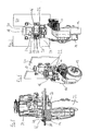
- Fig. 1 The arrangement of Fig. 1 includes a drive unit with a drive motor 50 and a drive wheel 52 which is rotatably mounted on an arm 54 about a horizontal axis. Fixedly connected to the housing of the motor 50 is a drawbar 56, which has two bearing eyes 58 for pivotally mounting a drawbar. A transmission with a transmission housing 60 is disposed below the drive motor 50.
- the entire drive unit with drive motor 50, drawbar 56, drive wheel 52 and gear housing 60 is rotatably mounted about a vertical axis in the drive carrier 62.
- the drive carrier has an annular body 64 which is substantially rotationally symmetrical.
- a bearing bed 66 is arranged, which is provided in a non-illustrated use of the drive carrier 62 for a truck with a decoupled from the rotational movement of the drive unit steering device and in which a bearing for the steering device used or a sliding or bearing surface can be incorporated.
- a tread 68 is formed on the inside of a lower portion of the annular body 64.
- this running surface 68 roll the rolling elements of the bearing for the drive unit, namely balls from.
- the annular body 64 forms an outer ring of the rolling bearing for receiving the Drive unit.
- the function of the inner ring is taken directly from the gear housing 60, in which a running surface 70 is incorporated.
- attachment arms 72 extend radially outwardly and downwardly.
- the attachment arms 72 each consist of two legs 72a, 72b beginning at a distance in the circumferential direction on the annular body 64 and converging radially outwards and downwards.
- At the outer ends of the fastening arms 72 are each a vertically aligned, cylindrical portion 74 having a bore 76.
- At the lower end of each cylindrical portion 74 is an annular abutment surface 78 which abuts the top of a frame plate 80 of the truck.
- a guided through the bore 76 screw 82 engages in a threaded bore 82 of the frame plate 80 and thus secures the drive carrier 62 on the frame plate 80th
- the drive motor 62 can be seen from above in the center and the drive carrier 62 can be seen therefrom.
- the drawbar 56 is also recognizable.
- the drive carrier 62 is screwed with three screws 82 to the frame plate 80 of the truck.
- the frame plate 80 in turn is firmly connected to other carriers 86 of the frame of the truck.
- FIGS. 1 and 2 The arrangement of FIGS. 1 and 2 is mounted in an industrial truck that is in Fig. 3 is shown. It has two load bearing means 88, which are arranged vertically adjustable on a mast 90. The drive part 92 of the truck is in the Fig. 3 provided with several covers. The truck is controlled by a drawbar 94 with a multi-function handle 96.
- FIGS. 5 to 7 were already explained in the introduction to the description.
Landscapes
- Engineering & Computer Science (AREA)
- Transportation (AREA)
- Structural Engineering (AREA)
- Civil Engineering (AREA)
- Life Sciences & Earth Sciences (AREA)
- Geology (AREA)
- Mechanical Engineering (AREA)
- Chemical & Material Sciences (AREA)
- Combustion & Propulsion (AREA)
- Arrangement Or Mounting Of Propulsion Units For Vehicles (AREA)
- Handcart (AREA)
- Rolling Contact Bearings (AREA)
Abstract
Description
- Die Erfindung betrifft einen Antriebsträger zur drehbaren Lagerung einer Antriebseinheit eines Flurförderzeugs, die ein Antriebsrad und einen Antriebsmotor umfasst, nach dem Oberbegriff des Anspruchs 1 bzw. des Anspruchs 6.
- Bei dem Flurförderzeug kann es sich insbesondere um ein deichselgeführtes Flurförderzeug mit einem elektrischen Fahrantrieb handeln. Bei derartigen Flurförderzeugen hat die Antriebseinheit häufig ein einziges Antriebsrad, das um eine horizontale Achse drehbar gelagert ist, beispielsweise in einem Schemel. Die Antriebseinheit hat einen Elektromotor, der über ein Getriebe das Antriebsrad antreibt. Die gesamte Antriebseinheit ist um eine vertikale Achse schwenkbar in dem Flurförderzeug gelagert, um eine Lenkbewegung ausführen zu können.
- Die
Figuren 6 und 7 zeigen einen Ausschnitt eines aus dem Stand der Technik bekannten Flurförderzeugs. Dieses weist eine Antriebseinheit mit einem Elektromotor 10 und einem Antriebsrad 12 auf. Die bekannte Antriebseinheit umfasst weiterhin ein Getriebe, das in einem Gehäuse 14 angeordnet ist. Die gesamte Antriebseinheit ist um eine vertikale Achse schwenkbar in einem Antriebsträger 16 gelagert. Der Antriebsträger 16 hat einen Befestigungsarm 18, der an einer Rahmenplatte 20 des Flurförderzeugs befestigt ist, und einen ringförmigen Körper 22, in dem die Antriebseinheit drehbar gelagert ist. Wie die teilweise geschnittene Darstellung derFig. 7 zeigt, ist diese drehbare Lagerung mit Hilfe von zwei Rollenlagern verwirklicht. Die Rollenlager weisen jeweils einen Innenring 24 und einen Außenring 26 auf, zwischen denen als Wälzkörper Rollen 28 angeordnet sind, und die jeweils eine Lauffläche für die Rollen des Rollenlagers aufweisen. Die Achsrichtungen der Rollen der beiden Rollenlager sind leicht gegeneinander geneigt, so dass das von den beiden Rollenlagern gebildete Lager sowohl Radial- als auch Axialkräfte aufnehmen kann. - Die beiden Innenringe 24 der Rollenlager sind auf einem zylindrischen Abschnitt 30 am oberen Ende der Antriebseinheit fest angeordnet. Die Außenringe 26 der beiden Rollenlager sind in Aufnahmeabschnitte des ringförmigen Körpers 22 des Antriebsträgers 16 eingepresst.
-
Fig. 5 zeigt eine Antriebseinheit eines anderen bekannten Flurförderzeugs. Diese umfasst ein Antriebsrad 32, einen Antriebsmotor 34 und ein Getriebe 36. Die Antriebseinheit ist um eine vertikale Achse schwenkbar in einer horizontal angeordneten Rahmenplatte 38 des Flurförderzeugs gelagert. Hierzu dient ein Kugellager mit einem Innenring 40, der einen zylindrischen Abschnitt des Gehäuses des Getriebes 36 und des Gehäuses des Motors 34 umschließt. Ein Außenring 42 des Kugellagers weist einen ringförmigen Flansch auf, der mit der Rahmenplatte 38 verschraubt ist. Innenring 40 und Außenring 42 weisen jeweils eine Lauffläche für die Kugeln 44 des Kugellagers auf. - Davon ausgehend ist es die Aufgabe der Erfindung, einen Antriebsträger zur drehbaren Lagerung einer Antriebseinheit eines Flurförderzeugs, die ein Antriebsrad und einen Antriebsmotor umfasst, anzugeben, der eine kostengünstigere Fertigung und Montage des Flurförderzeugs und einen kompakten Aufbau erlaubt.
- Diese Aufgabe wird gelöst durch den Antriebsträger mit den Merkmalen des Anspruchs 1. Vorteilhafte Ausgestaltungen sind in den sich anschließenden Unteransprüchen angegeben.
- Der erfindungsgemäße Antriebsträger hat
- einen ringförmigen Körper und
- mindestens einen radial und/oder axial von dem ringförmigen Körper vorstehenden Befestigungsarm zur Befestigung des ringförmigen Körpers an einem Rahmen des Flurförderzeugs, wobei
- der Antriebsträger einteilig aus einem einzigen Rohteil gefertigt ist und
- der ringförmige Körper eine Gleitfläche für ein Gleitlager oder eine Lauffläche für Wälzkörper eines Wälzlagers zur Aufnahme der drehbar zu lagernden Antriebseinheit aufweist.
- Der ringförmige Körper umschließt eine Öffnung, in die die Antriebseinheit einsetzbar ist. Abgesehen von der Gleit- bzw. Lauffläche ist er nicht notwendigerweise rotationssymmetrisch. Insbesondere an seiner Außenseite kann der ringförmige Körper eine recht- oder vieleckige Grundform aufweisen, wobei die Ecken mehr oder weniger stark abgerundet sein können. Die Befestigungsarme können in diesem Fall beispielsweise von den Eckbereichen des ringförmigen Körpers vorstehen oder von diesen gebildet sein.
- Im Gegensatz zu einem herkömmlichen, mit einer Rahmenplatte verbindbaren Außenring eines Lagers hat der erfindungsgemäße Antriebsträger vorstehende Befestigungsarme. Er hat daher keine vollständig rotationssymmetrische Form und kann, anders als ein herkömmlicher Außenring, nicht vollständig durch Drehen hergestellt werden. Es handelt sich bei dem Antriebsträger vielmehr um ein Bauteil mit einer komplexen Geometrie, das dem Konstrukteur viele Freiheiten bei der Anordnung der Antriebseinheit mit Bezug auf den Rahmen des Flurförderzeugs lässt. Insbesondere kann eine Ebene des Lagers gegenüber dem Fahrzeugrahmen geneigt und/oder beabstandet sein. Der Antriebsträger ist einteilig aus einem einzigen Rohteil gefertigt. Das Rohteil kann beispielsweise ein Guss- oder Schmiedeteil sein.
- Zur Lagerung der Antriebseinheit in dem Antriebsträger ist ein Gleitlager oder ein Wälzlager vorgesehen, das die drehbar zu lagernde Antriebseinheit aufnimmt. Die dem Antriebsträger zugeordnete Gleitfläche im Falle eines Gleitlagers bzw. die Lauffläche für Wälzkörper im Falle eines Wälzlagers ist bei der Erfindung unmittelbar an dem ringförmigen Körper des Antriebsträgers ausgebildet. Dadurch kann ein separater Lagerring eingespart werden, und die Montage eines solchen Rings entfällt. Die Gleitfläche ist diejenige Fläche des Gleitlagers, an der eine an der Antriebseinheit ausgebildete Gleitfläche entlang gleitet. Die Lauffläche für Wälzkörper eines Wälzlagers ist diejenige Fläche, auf der die Wälzkörper des Wälzlagers abrollen. Bei den Wälzkörpern kann es sich beispielsweise um Kugeln, Rollen oder Nadeln handeln. Die Gleit- bzw. Lauffläche kann durch mechanische Bearbeitung eine Oberfläche des Antriebsträgers hergestellt werden, beispielsweise durch Drehen oder Fräsen, Schleifen oder Polieren.
- Durch die erfindungsgemäße Integration der Gleit- bzw. Lauffläche in den Antriebsträger kann sich der Aufbau und die Montage des Flurförderzeugs vereinfachen. Sie kann auch einen kompakteren Aufbau ermöglichen.
- In einer Ausgestaltung weist der mindestens eine Befestigungsarm mindestens eine Bohrung auf zur Befestigung des Antriebsträgers an dem Rahmen des Flurförderzeugs mittels Schrauben und/oder Bolzen. Grundsätzlich kann der Befestigungsarm auf beliebige Weise mit dem Rahmen des Flurförderzeugs verbunden werden. Eine Befestigung mittels Schrauben und/oder Bolzen ist besonders zweckmäßig und kann bei Bedarf einfach wieder gelöst werden.
- In einer Ausgestaltung erstreckt sich der mindestens eine Befestigungsarm ausgehend von dem ringförmigen Körper radial nach außen und schräg nach unten.
- Die Richtungsangabe "nach unten" bezieht sich dabei auf die vorgesehene Montageposition des Antriebsträgers in einem Flurförderzeug. Bei dieser Anordnung kann der mindestens eine Befestigungsarm einen Abstand zwischen der Lagerung der Antriebseinheit und dem Rahmen des Flurförderzeugs überbrücken.
- Gemäß einer Ausgestaltung ist eine Befestigungsfläche des mindestens einen Befestigungsarms, die im montierten Zustand des Antriebsträgers an ein rahmenfestes Element des Flurförderzeugs angrenzt, in einem Abstand in Richtung der Symmetrieachse der Gleit- oder Lauffläche von der Gleit- oder Lauffläche angeordnet. Das rahmenfeste Element kann entweder ein Teil des Rahmens des Flurförderzeugs selbst oder ein bezüglich des Rahmens fest angeordnetes Zwischenstück, etwa eine Unterlegscheibe oder dergleichen, sein. Durch die genannte Anordnung der Befestigungsfläche kann das Lager für die Antriebseinheit in einer bevorzugten Position unter- oder oberhalb des rahmenfesten Elements angeordnet werden.
- In einer Ausgestaltung ist die Gleit- oder Lauffläche an einer Innenseite des ringförmigen Körpers angeordnet. Grundsätzlich kann die Gleit- oder Lauffläche auch an einer Außenseite des ringförmigen Körpers ausgebildet und von einem außenringförmigen Gegenstück an der Antriebseinheit umgriffen werden, oder beispielsweise an einer Ober- und/oder Unterseite des ringförmigen Körpers. Bevorzugt ist die Gleit- oder Lauffläche jedoch an einer Innenseite des ringförmigen Körpers ausgebildet, so dass der ringförmige Körper des Antriebsträgers einen Außenring des Lagers bildet.
- Die oben genannte Aufgabe wird ebenfalls gelöst durch den Antriebsträger mit den Merkmalen des Anspruchs 6. Vorteilhafte Ausgestaltungen sind in den sich anschließenden Unteransprüchen angegeben.
- Der erfindungsgemäße Antriebsträger dient zur drehbaren Lagerung einer Antriebseinheit eines Flurförderzeugs, die ein Antriebsrad mit einem Antriebsmotor umfasst, und weist folgendes auf:
- einen Träger, der einen Teil eines Rahmens des Flurförderzeugs bildet, und
- eine Gleitfläche für ein Gleitlager oder eine Lauffläche für Wälzkörper eines Wälzlagers zur Aufnahme der drehbar zu lagernden Antriebseinheit, wobei
- der Antriebsträger einteilig aus einem einzigen Rohteil gefertigt ist und
- die Gleit- oder Lauffläche in oder an dem Träger ausgebildet ist.
- Hinsichtlich der Merkmale des Antriebsträgers gemäß Anspruch 6, die bei dem vorstehend erläuterten Antriebsträger und seinen besonderen Ausgestaltungen ebenfalls vorhanden sind, wird auf die obigen Erläuterungen verwiesen, die analog auch für den Antriebsträger gemäß Anspruch 6 gelten.
- Der Antriebsträger nach Anspruch 6 bildet selbst einen Teil des Rahmens des Flurförderzeugs. Dieser Teil kann beispielsweise ein Quer- oder Längsträger oder ein sonstiger Träger des Flurförderzeugrahmens sein. Der Rahmen des Flurförderzeugs bildet eine Tragstruktur, an der die Räder des Flurförderzeugs befestigt und ein Lasttragmittel des Flurförderzeugs gehalten, geführt oder abgestützt ist.
- Die Gleit- bzw. Lauffläche ist in oder an dem Träger, der einen Teil des Rahmens bildet, ausgebildet. Beispielsweise kann die Gleitfläche durch entsprechende Oberflächenbearbeitung einer zylindrischen Fläche des Trägers gebildet werden. Die Lauffläche für Wälzkörper eines Wälzlagers kann beispielsweise durch mechanische Bearbeitung durch Drehen oder Fräsen in den Träger eingebracht sein. Der Antriebsträger mit Träger und Gleit- bzw. Lauffläche ist einteilig aus einem einzigen Rohteil gefertigt.
- In einer Ausgestaltung ist der Träger zur unlösbaren Verbindung mit weiteren Rahmenteilen ausgebildet. Beispielsweise kann der Träger zum Verschweißen mit weiteren Trägern des Rahmens vorgesehen sein. Der Antriebsträger und die übrigen Rahmenteile bilden dann nach Montage des Antriebsträgers eine unlösbar miteinander verbundene Einheit.
- In einer weiteren Ausgestaltung weist der Antriebsträger ein Lagerbett oder eine weitere Gleit- oder Lauffläche zur Aufnahme einer gegenüber dem Antriebsträger drehbar zu lagernden Lenkeinrichtung auf. Die Lenkeinrichtung kann beispielsweise ein mit einer Deichsel zu verbindender Deichselbock sein. Die Lenkeinrichtung kann mit Hilfe eines Gleit- oder Wälzlagers drehbar an dem Antriebsträger gelagert sein. Hierzu kann entweder ein konventionelles, einen Innen- und Außenring aufweisendes Gleit- oder Wälzlager in das Lagerbett des Antriebsträgers eingesetzt werden. Alternativ kann der Antriebsträger eine weitere Gleit- oder Lauffläche aufweisen, die wie diejenige für die Lagerung der Antriebseinheit integral mit dem Antriebsträger ausgebildet ist. In beiden Fällen erfüllt der Antriebsträger eine Doppelfunktion, indem er sowohl die Antriebseinheit als auch die Lenkeinrichtung lagert. Dadurch kann der Montage- und Bauteilaufwand weiter reduziert werden.
- Eine gegenüber dem Antriebsträger drehbare Lenkeinrichtung, die unabhängig von der Antriebseinheit gelagert wird, findet Verwendung insbesondere bei Flurförderzeugen, die zur Drehung der Antriebseinheit einen Lenkantrieb aufweisen, wobei die Drehbewegung der Lenkeinrichtung von der Drehbewegung der Antriebseinheit entkoppelt ist.
- Die obige Aufgabe wird ebenfalls gelöst durch das Antriebssystem mit den Merkmalen des Anspruchs 9. Es weist eine Antriebseinheit mit einem Antriebsmotor und einem Antriebsrad sowie einen Antriebsträger nach einem der Ansprüche 1 bis 8 auf.
- In einer Ausgestaltung des Antriebssystems weist die Antriebseinheit eine mit der Gleit- oder Lauffläche des Antriebsträgers zusammenwirkende Gleit- bzw. Lauffläche auf, die an einem Gehäuse des Antriebsmotors oder an einem Gehäuse eines Getriebes der Antriebseinheit ausgebildet und einteilig mit diesem gefertigt ist. Grundsätzlich kann die der Antriebseinheit zugeordnete Gleit- oder Lauffläche auch als separater Lagerring, der mit der Antriebseinheit verbunden wird, ausgeführt werden. Vorteilhaft kann jedoch auch aus diese Gleit- oder Lauffläche unmittelbar in ein Gehäuse der Antriebseinheit integriert werden.
- Die obige Aufgabe wird ebenfalls gelöst durch das Flurförderzeug mit den Merkmalen des Anspruchs 11. Das erfindungsgemäße Flurförderzeug weist ein Antriebssystem nach Anspruch 9 oder 10 auf.
- Die Erfindung wird nachfolgend anhand eines in vier Figuren dargestellten Ausführungsbeispiels näher erläutert. Es zeigen:
- Fig. 1
- einen erfindungsgemäßen Antriebsträger mit einer Antriebseinheit im montierten Zustand in einer teilweise geschnittenen Darstellung;
- Fig. 2
- eine Draufsicht auf die Anordnung aus
Fig. 1 von oben; - Fig. 3
- ein erfindungsgemäßes Flurförderzeug in einer perspektivischen Ansicht;
- Fig. 4
- das Flurförderzeug aus
Fig. 3 mit einer entfernten Abdeckung in einer weiteren perspektivischen Ansicht; - Fig. 5
- eine montierte Antriebseinheit eines Flurförderzeugs nach dem Stand der Technik in einer teilweise geschnittenen Darstellung;
- Fig. 6
- eine weitere montierte Antriebseinheit eines anderen aus dem Stand der Technik bekannten Flurförderzeugs in einer perspektivischen Ansicht;
- Fig. 7
- die Antriebseinheit aus
Fig. 6 in einer teilweise geschnittenen Darstellung. - Die Anordnung der
Fig. 1 umfasst eine Antriebseinheit mit einem Antriebsmotor 50 und einem Antriebsrad 52, das um eine horizontale Achse drehbar an einem Arm 54 gelagert ist. Fest mit dem Gehäuse des Motors 50 verbunden ist ein Deichselbock 56, der zwei Lageraugen 58 zur schwenkbaren Befestigung einer Deichsel aufweist. Ein Getriebe mit einem Getriebegehäuse 60 ist unterhalb des Antriebsmotors 50 angeordnet. - Die gesamte Antriebseinheit mit Antriebsmotor 50, Deichselbock 56, Antriebsrad 52 und Getriebegehäuse 60 ist um eine vertikale Achse drehbar in dem Antriebsträger 62 gelagert. Der Antriebsträger hat einen ringförmigen Körper 64, der im Wesentlichen rotationssymmetrisch ist. An der Innenseite eines oberen Abschnitts des ringförmigen Körpers 64 ist ein Lagerbett 66 angeordnet, das bei einer nicht dargestellten Verwendung des Antriebsträgers 62 für ein Flurförderzeug mit einer von der Drehbewegung der Antriebseinheit entkoppelten Lenkeinrichtung vorgesehen ist und in das ein Lager für die Lenkeinrichtung eingesetzt bzw. eine Gleit- oder Lagerfläche eingearbeitet werden kann.
- An der Innenseite eines unteren Abschnitts des ringförmigen Körpers 64 ist eine Lauffläche 68 ausgebildet. Auf dieser Lauffläche 68 rollen die Wälzkörper des Lagers für die Antriebseinheit, nämlich Kugeln, ab. In diesem Sinne bildet der ringförmige Körper 64 einen Außenring des Wälzlagers zur Aufnahme der Antriebseinheit. Die Funktion des Innenrings wird unmittelbar von dem Getriebegehäuse 60 übernommen, in das eine Lauffläche 70 eingearbeitet ist.
- Ausgehend von der Außenseite des ringförmigen Körpers 64 erstrecken sich Befestigungsarme 72 radial nach außen und nach unten. Die Befestigungsarme 72 bestehen jeweils aus zwei in einem Abstand in Umfangsrichtung an dem ringförmigen Körper 64 beginnenden, radial nach außen und unten schräg zusammenlaufenden Schenkeln 72a, 72b. An den äußeren Enden der Befestigungsarme 72 befindet sich jeweils ein vertikal ausgerichteter, zylinderförmiger Abschnitt 74, der eine Bohrung 76 aufweist. Am unteren Ende jedes zylindrischen Abschnitts 74 befindet sich eine ringförmige Anlagefläche 78, die an die Oberseite einer Rahmenplatte 80 des Flurförderzeugs angrenzt. Eine durch die Bohrung 76 hindurch geführte Schraube 82 greift in eine Gewindebohrung 82 der Rahmenplatte 80 ein und befestigt so den Antriebsträger 62 an der Rahmenplatte 80.
- In der Ansicht der
Fig. 2 von oben ist in der Mitte der Antriebsmotor 50 erkennbar und außerhalb davon der Antriebsträger 62. Ebenfalls erkennbar ist der Deichselbock 56. Besonders deutlich wird die Anordnung der drei Befestigungsarme 72, die bezüglich der Symmetrieachse der Antriebseinheit asymmetrisch angeordnet sind. Der Antriebsträger 62 ist mit drei Schrauben 82 mit der Rahmenplatte 80 des Flurförderzeugs verschraubt. Die Rahmenplatte 80 wiederum ist mit weiteren Trägern 86 des Rahmens des Flurförderzeugs fest verbunden. - Die Anordnung der
Figuren 1 und2 ist montiert in einem Flurförderzeug, das inFig. 3 dargestellt ist. Es weist zwei Lasttragmittel 88 auf, die an einem Hubgerüst 90 höhenverstellbar angeordnet sind. Der Antriebsteil 92 des Flurförderzeugs ist in derFig. 3 mit mehreren Abdeckungen versehen. Gesteuert wird das Flurförderzeug über eine Deichsel 94 mit einem Multifunktionsgriff 96. - In der Ansicht der
Fig. 4 ist die Deichsel 94 und eine Abdeckung des Antriebsteils 92 entfernt. Dadurch ist die Antriebseinheit sichtbar, wobei in derFig. 4 insbesondere der Antriebsmotor 50 und der Antriebsträger 62 sowie deren vorgesehene Einbauposition erkennbar sind. - Die
Figuren 5 bis 7 wurden bereits in der Beschreibungseinleitung erläutert.
Claims (11)
- Antriebsträger (62) zur drehbaren Lagerung einer Antriebseinheit eines Flurförderzeugs, die ein Antriebsrad (52) und einen Antriebsmotor (50) umfasst, mit• einem ringförmigen Körper (64) und• mindestens einem radial und/oder axial von dem ringförmigen Körper (64) vorstehenden Befestigungsarm (72) zur Befestigung des ringförmigen Körpers (64) an einem Rahmen des Flurförderzeugs, wobei• der Antriebsträger (62) einteilig aus einem einzigen Rohteil gefertigt ist, dadurch gekennzeichnet, dass• der ringförmige Körper (64) eine Gleitfläche für ein Gleitlager oder eine Lauffläche (68) für Wälzkörper eines Wälzlagers zur Aufnahme der drehbar zu lagernden Antriebseinheit aufweist.
- Antriebsträger (62) nach Anspruch 1, dadurch gekennzeichnet, dass der mindestens eine Befestigungsarm (72) mindestens eine Bohrung (76) aufweist zur Befestigung des Antriebsträgers (62) an dem Rahmen des Flurförderzeugs mittels Schrauben (82) und/oder Bolzen.
- Antriebsträger nach Anspruch 1 oder 2, dadurch gekennzeichnet, dass sich der mindestens eine Befestigungsarm (72) ausgehend von dem ringförmigen Körper (64) radial nach außen und schräg nach unten erstreckt.
- Antriebsträger nach einem der Ansprüche 1 bis 3, dadurch gekennzeichnet, dass eine Befestigungsfläche (78) des mindestens einen Befestigungsarms (72), die im montierten Zustand des Antriebsträgers (62) an ein rahmenfestes Element (80) des Flurförderzeugs angrenzt, in einem Abstand in Richtung der Symmetrieachse der Gleit- oder Lauffläche (68) von der Gleit- oder Lauffläche (68) angeordnet ist.
- Antriebsträger (62) nach einem der Ansprüche 1 bis 4, dadurch gekennzeichnet, dass die Gleit- oder Lauffläche (68) an einer Innenseite des ringförmigen Körpers (64) angeordnet ist.
- Antriebsträger zur drehbaren Lagerung einer Antriebseinheit eines Flurförderzeugs, die ein Antriebsrad und einen Antriebsmotor umfasst, mit• einem Träger, der einen Teil eines Rahmens des Flurförderzeugs bildet, und• einer Gleitfläche für ein Gleitlager oder einer Lauffläche für Wälzkörper eines Wälzlagers zur Aufnahme der drehbar zu lagernden Antriebseinheit, dadurch gekennzeichnet, dass• der Antriebsträger einteilig aus einem einzigen Rohteil gefertigt ist, wobei die Gleit- oder Lauffläche in oder an dem Träger ausgebildet ist.
- Antriebsträger nach Anspruch 6, dadurch gekennzeichnet, dass der Träger zur unlösbaren Verbindung mit weiteren Rahmenteilen ausgebildet ist.
- Antriebsträger (62) nach einem der Ansprüche 1 bis 7, dadurch gekennzeichnet, dass der Antriebsträger (62) ein Lagerbett (66) oder eine weitere Gleit- oder Lauffläche zur Aufnahme einer gegenüber dem Antriebsträger (62) drehbar zu lagernden Lenkeinrichtung aufweist.
- Antriebssystem umfassend eine Antriebseinheit mit einem Antriebsmotor (50) und einem Antriebsrad (52) sowie einen Antriebsträger (62) nach einem der Ansprüche 1 bis 8.
- Antriebssystem nach Anspruch 9, dadurch gekennzeichnet, dass die Antriebseinheit eine mit der Gleit- oder Lauffläche (68) des Antriebsträgers (62) zusammenwirkende Gleit- bzw. Lauffläche aufweist, die an einem Gehäuse des Antriebsmotors oder an einem Gehäuse eines Getriebes der Antriebseinheit ausgebildet und einteilig mit diesem gefertigt ist.
- Flurförderzeug mit einem Antriebssystem nach Anspruch 9 oder 10.
Applications Claiming Priority (1)
| Application Number | Priority Date | Filing Date | Title |
|---|---|---|---|
| DE200910038651 DE102009038651A1 (de) | 2009-08-14 | 2009-08-14 | Antriebsträger zur drehbaren Lagerung einer Antriebseinheit eines Flurförderzeugs |
Publications (3)
| Publication Number | Publication Date |
|---|---|
| EP2284118A2 true EP2284118A2 (de) | 2011-02-16 |
| EP2284118A3 EP2284118A3 (de) | 2011-12-21 |
| EP2284118B1 EP2284118B1 (de) | 2012-12-05 |
Family
ID=43127283
Family Applications (1)
| Application Number | Title | Priority Date | Filing Date |
|---|---|---|---|
| EP20100007892 Active EP2284118B1 (de) | 2009-08-14 | 2010-07-29 | Antriebsträger zur drehbaren Lagerung einer Antriebseinheit eines Flurförderzeugs |
Country Status (2)
| Country | Link |
|---|---|
| EP (1) | EP2284118B1 (de) |
| DE (1) | DE102009038651A1 (de) |
Family Cites Families (11)
| Publication number | Priority date | Publication date | Assignee | Title |
|---|---|---|---|---|
| DE20221136U1 (de) * | 1970-02-26 | 2005-06-09 | Still S.A.R.L. | Antriebseinheit für ein Flurförderzeug |
| SE349610B (de) * | 1971-02-05 | 1972-10-02 | Skf Ind Trading & Dev | |
| SE348839B (de) * | 1971-04-21 | 1972-09-11 | Skf Ind Trading & Dev | |
| US3838899A (en) * | 1973-07-27 | 1974-10-01 | Gen Motors Corp | Axially preloaded bearing assembly |
| DE19522456C2 (de) * | 1995-06-21 | 1999-12-30 | Jungheinrich Ag | Deichselhubwagen |
| JPH09151950A (ja) * | 1995-11-30 | 1997-06-10 | Ntn Corp | 自動車の車輪用軸受装置 |
| JP3699249B2 (ja) * | 1997-07-28 | 2005-09-28 | Ntn株式会社 | ハブユニット軸受およびその製造方法 |
| JP4724970B2 (ja) * | 2001-07-19 | 2011-07-13 | 株式会社ジェイテクト | 車軸用軸受装置 |
| DE202005020633U1 (de) * | 2005-04-15 | 2006-10-26 | Zf Friedrichshafen Ag | Antrieb für ein Flurförderzeug |
| DE102006041684A1 (de) * | 2006-09-06 | 2008-03-27 | Jungheinrich Ag | Vormontageeinheit für den Antrieb eines Flurförderzeugs |
| EP2030939B1 (de) * | 2007-08-31 | 2013-03-20 | BT Products AB | Flurförderzeug |
-
2009
- 2009-08-14 DE DE200910038651 patent/DE102009038651A1/de not_active Withdrawn
-
2010
- 2010-07-29 EP EP20100007892 patent/EP2284118B1/de active Active
Non-Patent Citations (1)
| Title |
|---|
| None |
Also Published As
| Publication number | Publication date |
|---|---|
| DE102009038651A1 (de) | 2011-02-24 |
| EP2284118B1 (de) | 2012-12-05 |
| EP2284118A3 (de) | 2011-12-21 |
Similar Documents
| Publication | Publication Date | Title |
|---|---|---|
| DE102007051299B4 (de) | Höhenverstellvorrichtung für Kraftfahrzeuge | |
| DE102020126719B3 (de) | Antriebs- und Lenkeinheit für Flurförderfahrzeuge | |
| DE102009023079A1 (de) | Rundschalttisch | |
| DE102011055416A1 (de) | Teleskopierbare Hubsäule eines Möbelteils | |
| DE102014107292B3 (de) | Lenksäule für ein Kraftfahrzeug | |
| DE102008060477B4 (de) | Anordnung zur Niveauregulierung eines Fahrzeugs | |
| EP1970228B1 (de) | Höhenverstellvorrichtung für Kraftfahrzeuge | |
| EP2284117B1 (de) | Lagerbauteil zur Lagerung einer Antriebs- und Lenkeinheit eines Flurförderzeugs | |
| EP3838674A1 (de) | Ausfahrbare trittstufe | |
| DE10328651A1 (de) | Antriebseinheit mit einem Drehschemel, einem Fahrmotor und einem Lenkmotor | |
| EP3765316B1 (de) | Fahrzeugfederung mit regelbarer bodenfreiheit und steifigkeit | |
| WO2009092501A2 (de) | Federbeinlager | |
| EP1932799A1 (de) | Flurförderzeug | |
| EP3156274A1 (de) | Antriebseinheit für ein flurförderfahrzeug | |
| EP2284118B1 (de) | Antriebsträger zur drehbaren Lagerung einer Antriebseinheit eines Flurförderzeugs | |
| WO2010060750A1 (de) | Lenkgetriebe | |
| DE102013106221A1 (de) | Scheibenwischermotor | |
| EP2562058B1 (de) | Modular aufgebaute Stützvorrichtung für einen Sattelanhänger und Sattelanhänger mit einer solchen Stützvorrichtung | |
| DE102007026107A1 (de) | Kraftfahrzeugsitzverstellantrieb | |
| DE102017008439A1 (de) | Antriebsvorrichtung für ein Flurförderfahrzeug | |
| EP3105090A1 (de) | Teleskopstütze mit spindel und deren antrieb über tellerrad mit integriertem axiallager zur lastabstützung | |
| EP3898381B1 (de) | Hilfskraftantrieb für eine lenksäule und lenksäule für ein kraftfahrzeug | |
| DE102006035915A1 (de) | Hubeinrichtung | |
| EP2265451B1 (de) | Verschwenkbare anhängerkupplung | |
| DE102006012342A1 (de) | Achsmittengetriebe mit Durchtrieb |
Legal Events
| Date | Code | Title | Description |
|---|---|---|---|
| PUAI | Public reference made under article 153(3) epc to a published international application that has entered the european phase |
Free format text: ORIGINAL CODE: 0009012 |
|
| AK | Designated contracting states |
Kind code of ref document: A2 Designated state(s): AL AT BE BG CH CY CZ DE DK EE ES FI FR GB GR HR HU IE IS IT LI LT LU LV MC MK MT NL NO PL PT RO SE SI SK SM TR |
|
| AX | Request for extension of the european patent |
Extension state: BA ME RS |
|
| PUAL | Search report despatched |
Free format text: ORIGINAL CODE: 0009013 |
|
| AK | Designated contracting states |
Kind code of ref document: A3 Designated state(s): AL AT BE BG CH CY CZ DE DK EE ES FI FR GB GR HR HU IE IS IT LI LT LU LV MC MK MT NL NO PL PT RO SE SI SK SM TR |
|
| AX | Request for extension of the european patent |
Extension state: BA ME RS |
|
| RIC1 | Information provided on ipc code assigned before grant |
Ipc: B60K 7/00 20060101ALI20111114BHEP Ipc: B66F 9/075 20060101AFI20111114BHEP |
|
| 17P | Request for examination filed |
Effective date: 20120605 |
|
| RIC1 | Information provided on ipc code assigned before grant |
Ipc: B66F 9/075 20060101AFI20120716BHEP |
|
| GRAP | Despatch of communication of intention to grant a patent |
Free format text: ORIGINAL CODE: EPIDOSNIGR1 |
|
| GRAS | Grant fee paid |
Free format text: ORIGINAL CODE: EPIDOSNIGR3 |
|
| GRAA | (expected) grant |
Free format text: ORIGINAL CODE: 0009210 |
|
| AK | Designated contracting states |
Kind code of ref document: B1 Designated state(s): AL AT BE BG CH CY CZ DE DK EE ES FI FR GB GR HR HU IE IS IT LI LT LU LV MC MK MT NL NO PL PT RO SE SI SK SM TR |
|
| REG | Reference to a national code |
Ref country code: GB Ref legal event code: FG4D Free format text: NOT ENGLISH |
|
| REG | Reference to a national code |
Ref country code: CH Ref legal event code: EP |
|
| REG | Reference to a national code |
Ref country code: AT Ref legal event code: REF Ref document number: 587181 Country of ref document: AT Kind code of ref document: T Effective date: 20121215 |
|
| REG | Reference to a national code |
Ref country code: IE Ref legal event code: FG4D Free format text: LANGUAGE OF EP DOCUMENT: GERMAN |
|
| REG | Reference to a national code |
Ref country code: SE Ref legal event code: TRGR |
|
| REG | Reference to a national code |
Ref country code: DE Ref legal event code: R096 Ref document number: 502010001779 Country of ref document: DE Effective date: 20130124 |
|
| PG25 | Lapsed in a contracting state [announced via postgrant information from national office to epo] |
Ref country code: LT Free format text: LAPSE BECAUSE OF FAILURE TO SUBMIT A TRANSLATION OF THE DESCRIPTION OR TO PAY THE FEE WITHIN THE PRESCRIBED TIME-LIMIT Effective date: 20121205 Ref country code: FI Free format text: LAPSE BECAUSE OF FAILURE TO SUBMIT A TRANSLATION OF THE DESCRIPTION OR TO PAY THE FEE WITHIN THE PRESCRIBED TIME-LIMIT Effective date: 20121205 Ref country code: ES Free format text: LAPSE BECAUSE OF FAILURE TO SUBMIT A TRANSLATION OF THE DESCRIPTION OR TO PAY THE FEE WITHIN THE PRESCRIBED TIME-LIMIT Effective date: 20130316 Ref country code: NO Free format text: LAPSE BECAUSE OF FAILURE TO SUBMIT A TRANSLATION OF THE DESCRIPTION OR TO PAY THE FEE WITHIN THE PRESCRIBED TIME-LIMIT Effective date: 20130305 |
|
| REG | Reference to a national code |
Ref country code: NL Ref legal event code: VDEP Effective date: 20121205 |
|
| REG | Reference to a national code |
Ref country code: LT Ref legal event code: MG4D |
|
| PG25 | Lapsed in a contracting state [announced via postgrant information from national office to epo] |
Ref country code: PL Free format text: LAPSE BECAUSE OF FAILURE TO SUBMIT A TRANSLATION OF THE DESCRIPTION OR TO PAY THE FEE WITHIN THE PRESCRIBED TIME-LIMIT Effective date: 20121205 Ref country code: SI Free format text: LAPSE BECAUSE OF FAILURE TO SUBMIT A TRANSLATION OF THE DESCRIPTION OR TO PAY THE FEE WITHIN THE PRESCRIBED TIME-LIMIT Effective date: 20121205 Ref country code: LV Free format text: LAPSE BECAUSE OF FAILURE TO SUBMIT A TRANSLATION OF THE DESCRIPTION OR TO PAY THE FEE WITHIN THE PRESCRIBED TIME-LIMIT Effective date: 20121205 Ref country code: GR Free format text: LAPSE BECAUSE OF FAILURE TO SUBMIT A TRANSLATION OF THE DESCRIPTION OR TO PAY THE FEE WITHIN THE PRESCRIBED TIME-LIMIT Effective date: 20130306 |
|
| PG25 | Lapsed in a contracting state [announced via postgrant information from national office to epo] |
Ref country code: IS Free format text: LAPSE BECAUSE OF FAILURE TO SUBMIT A TRANSLATION OF THE DESCRIPTION OR TO PAY THE FEE WITHIN THE PRESCRIBED TIME-LIMIT Effective date: 20130405 Ref country code: EE Free format text: LAPSE BECAUSE OF FAILURE TO SUBMIT A TRANSLATION OF THE DESCRIPTION OR TO PAY THE FEE WITHIN THE PRESCRIBED TIME-LIMIT Effective date: 20121205 Ref country code: CZ Free format text: LAPSE BECAUSE OF FAILURE TO SUBMIT A TRANSLATION OF THE DESCRIPTION OR TO PAY THE FEE WITHIN THE PRESCRIBED TIME-LIMIT Effective date: 20121205 Ref country code: SK Free format text: LAPSE BECAUSE OF FAILURE TO SUBMIT A TRANSLATION OF THE DESCRIPTION OR TO PAY THE FEE WITHIN THE PRESCRIBED TIME-LIMIT Effective date: 20121205 Ref country code: BG Free format text: LAPSE BECAUSE OF FAILURE TO SUBMIT A TRANSLATION OF THE DESCRIPTION OR TO PAY THE FEE WITHIN THE PRESCRIBED TIME-LIMIT Effective date: 20130305 |
|
| PG25 | Lapsed in a contracting state [announced via postgrant information from national office to epo] |
Ref country code: RO Free format text: LAPSE BECAUSE OF FAILURE TO SUBMIT A TRANSLATION OF THE DESCRIPTION OR TO PAY THE FEE WITHIN THE PRESCRIBED TIME-LIMIT Effective date: 20121205 Ref country code: PT Free format text: LAPSE BECAUSE OF FAILURE TO SUBMIT A TRANSLATION OF THE DESCRIPTION OR TO PAY THE FEE WITHIN THE PRESCRIBED TIME-LIMIT Effective date: 20130405 Ref country code: NL Free format text: LAPSE BECAUSE OF FAILURE TO SUBMIT A TRANSLATION OF THE DESCRIPTION OR TO PAY THE FEE WITHIN THE PRESCRIBED TIME-LIMIT Effective date: 20121205 |
|
| PLBE | No opposition filed within time limit |
Free format text: ORIGINAL CODE: 0009261 |
|
| STAA | Information on the status of an ep patent application or granted ep patent |
Free format text: STATUS: NO OPPOSITION FILED WITHIN TIME LIMIT |
|
| PG25 | Lapsed in a contracting state [announced via postgrant information from national office to epo] |
Ref country code: DK Free format text: LAPSE BECAUSE OF FAILURE TO SUBMIT A TRANSLATION OF THE DESCRIPTION OR TO PAY THE FEE WITHIN THE PRESCRIBED TIME-LIMIT Effective date: 20121205 |
|
| 26N | No opposition filed |
Effective date: 20130906 |
|
| PG25 | Lapsed in a contracting state [announced via postgrant information from national office to epo] |
Ref country code: HR Free format text: LAPSE BECAUSE OF FAILURE TO SUBMIT A TRANSLATION OF THE DESCRIPTION OR TO PAY THE FEE WITHIN THE PRESCRIBED TIME-LIMIT Effective date: 20121205 Ref country code: CY Free format text: LAPSE BECAUSE OF FAILURE TO SUBMIT A TRANSLATION OF THE DESCRIPTION OR TO PAY THE FEE WITHIN THE PRESCRIBED TIME-LIMIT Effective date: 20121205 |
|
| REG | Reference to a national code |
Ref country code: DE Ref legal event code: R097 Ref document number: 502010001779 Country of ref document: DE Effective date: 20130906 |
|
| BERE | Be: lapsed |
Owner name: JUNGHEINRICH A.G. Effective date: 20130731 |
|
| PG25 | Lapsed in a contracting state [announced via postgrant information from national office to epo] |
Ref country code: MC Free format text: LAPSE BECAUSE OF FAILURE TO SUBMIT A TRANSLATION OF THE DESCRIPTION OR TO PAY THE FEE WITHIN THE PRESCRIBED TIME-LIMIT Effective date: 20121205 |
|
| REG | Reference to a national code |
Ref country code: IE Ref legal event code: MM4A |
|
| PG25 | Lapsed in a contracting state [announced via postgrant information from national office to epo] |
Ref country code: BE Free format text: LAPSE BECAUSE OF NON-PAYMENT OF DUE FEES Effective date: 20130731 |
|
| PG25 | Lapsed in a contracting state [announced via postgrant information from national office to epo] |
Ref country code: IE Free format text: LAPSE BECAUSE OF NON-PAYMENT OF DUE FEES Effective date: 20130729 |
|
| REG | Reference to a national code |
Ref country code: CH Ref legal event code: PL |
|
| PG25 | Lapsed in a contracting state [announced via postgrant information from national office to epo] |
Ref country code: CH Free format text: LAPSE BECAUSE OF NON-PAYMENT OF DUE FEES Effective date: 20140731 Ref country code: LI Free format text: LAPSE BECAUSE OF NON-PAYMENT OF DUE FEES Effective date: 20140731 |
|
| PG25 | Lapsed in a contracting state [announced via postgrant information from national office to epo] |
Ref country code: SM Free format text: LAPSE BECAUSE OF FAILURE TO SUBMIT A TRANSLATION OF THE DESCRIPTION OR TO PAY THE FEE WITHIN THE PRESCRIBED TIME-LIMIT Effective date: 20121205 |
|
| PG25 | Lapsed in a contracting state [announced via postgrant information from national office to epo] |
Ref country code: MT Free format text: LAPSE BECAUSE OF FAILURE TO SUBMIT A TRANSLATION OF THE DESCRIPTION OR TO PAY THE FEE WITHIN THE PRESCRIBED TIME-LIMIT Effective date: 20121205 Ref country code: TR Free format text: LAPSE BECAUSE OF FAILURE TO SUBMIT A TRANSLATION OF THE DESCRIPTION OR TO PAY THE FEE WITHIN THE PRESCRIBED TIME-LIMIT Effective date: 20121205 |
|
| PG25 | Lapsed in a contracting state [announced via postgrant information from national office to epo] |
Ref country code: MK Free format text: LAPSE BECAUSE OF FAILURE TO SUBMIT A TRANSLATION OF THE DESCRIPTION OR TO PAY THE FEE WITHIN THE PRESCRIBED TIME-LIMIT Effective date: 20121205 Ref country code: HU Free format text: LAPSE BECAUSE OF FAILURE TO SUBMIT A TRANSLATION OF THE DESCRIPTION OR TO PAY THE FEE WITHIN THE PRESCRIBED TIME-LIMIT; INVALID AB INITIO Effective date: 20100729 Ref country code: LU Free format text: LAPSE BECAUSE OF NON-PAYMENT OF DUE FEES Effective date: 20130729 |
|
| REG | Reference to a national code |
Ref country code: FR Ref legal event code: PLFP Year of fee payment: 7 |
|
| REG | Reference to a national code |
Ref country code: AT Ref legal event code: MM01 Ref document number: 587181 Country of ref document: AT Kind code of ref document: T Effective date: 20150729 |
|
| PG25 | Lapsed in a contracting state [announced via postgrant information from national office to epo] |
Ref country code: AT Free format text: LAPSE BECAUSE OF NON-PAYMENT OF DUE FEES Effective date: 20150729 |
|
| PG25 | Lapsed in a contracting state [announced via postgrant information from national office to epo] |
Ref country code: SM Free format text: LAPSE BECAUSE OF FAILURE TO SUBMIT A TRANSLATION OF THE DESCRIPTION OR TO PAY THE FEE WITHIN THE PRESCRIBED TIME-LIMIT Effective date: 20140820 |
|
| REG | Reference to a national code |
Ref country code: FR Ref legal event code: PLFP Year of fee payment: 8 |
|
| REG | Reference to a national code |
Ref country code: FR Ref legal event code: PLFP Year of fee payment: 9 |
|
| PG25 | Lapsed in a contracting state [announced via postgrant information from national office to epo] |
Ref country code: AL Free format text: LAPSE BECAUSE OF FAILURE TO SUBMIT A TRANSLATION OF THE DESCRIPTION OR TO PAY THE FEE WITHIN THE PRESCRIBED TIME-LIMIT Effective date: 20121205 |
|
| PGFP | Annual fee paid to national office [announced via postgrant information from national office to epo] |
Ref country code: DE Payment date: 20250722 Year of fee payment: 16 |
|
| PGFP | Annual fee paid to national office [announced via postgrant information from national office to epo] |
Ref country code: IT Payment date: 20250731 Year of fee payment: 16 |
|
| PGFP | Annual fee paid to national office [announced via postgrant information from national office to epo] |
Ref country code: GB Payment date: 20250724 Year of fee payment: 16 |
|
| PGFP | Annual fee paid to national office [announced via postgrant information from national office to epo] |
Ref country code: FR Payment date: 20250723 Year of fee payment: 16 |
|
| PGFP | Annual fee paid to national office [announced via postgrant information from national office to epo] |
Ref country code: SE Payment date: 20250723 Year of fee payment: 16 |