EP2284032A1 - Fixing frame, heat exchanger and vehicle - Google Patents
Fixing frame, heat exchanger and vehicle Download PDFInfo
- Publication number
- EP2284032A1 EP2284032A1 EP10170157A EP10170157A EP2284032A1 EP 2284032 A1 EP2284032 A1 EP 2284032A1 EP 10170157 A EP10170157 A EP 10170157A EP 10170157 A EP10170157 A EP 10170157A EP 2284032 A1 EP2284032 A1 EP 2284032A1
- Authority
- EP
- European Patent Office
- Prior art keywords
- profile
- heat exchanger
- mounting frame
- fluid
- heat
- Prior art date
- Legal status (The legal status is an assumption and is not a legal conclusion. Google has not performed a legal analysis and makes no representation as to the accuracy of the status listed.)
- Granted
Links
Images


Classifications
-
- B—PERFORMING OPERATIONS; TRANSPORTING
- B60—VEHICLES IN GENERAL
- B60K—ARRANGEMENT OR MOUNTING OF PROPULSION UNITS OR OF TRANSMISSIONS IN VEHICLES; ARRANGEMENT OR MOUNTING OF PLURAL DIVERSE PRIME-MOVERS IN VEHICLES; AUXILIARY DRIVES FOR VEHICLES; INSTRUMENTATION OR DASHBOARDS FOR VEHICLES; ARRANGEMENTS IN CONNECTION WITH COOLING, AIR INTAKE, GAS EXHAUST OR FUEL SUPPLY OF PROPULSION UNITS IN VEHICLES
- B60K11/00—Arrangement in connection with cooling of propulsion units
- B60K11/02—Arrangement in connection with cooling of propulsion units with liquid cooling
- B60K11/04—Arrangement or mounting of radiators, radiator shutters, or radiator blinds
-
- F—MECHANICAL ENGINEERING; LIGHTING; HEATING; WEAPONS; BLASTING
- F28—HEAT EXCHANGE IN GENERAL
- F28F—DETAILS OF HEAT-EXCHANGE AND HEAT-TRANSFER APPARATUS, OF GENERAL APPLICATION
- F28F9/00—Casings; Header boxes; Auxiliary supports for elements; Auxiliary members within casings
- F28F9/001—Casings in the form of plate-like arrangements; Frames enclosing a heat exchange core
- F28F9/002—Casings in the form of plate-like arrangements; Frames enclosing a heat exchange core with fastening means for other structures
Definitions
- a relatively high cooling demand for the working fluids used due to the high drive power can be, for example, a charging fluid of an internal combustion engine, such as an exhaust gas or a charge air.
- a heat exchanger in the form of a charge-fluid heat exchanger for example a gas cooler, is used regularly.
- a heat exchanger in the form of a coolant radiator or the like is regularly provided.
- Such and other heat exchangers, in particular Cooling modules can be relatively heavy - accordingly, they are attached by comparatively complex elements on the vehicle.
- the fasteners must not only support the dead weight of the heat exchanger, but also be designed to withstand dynamic loads, such as shock or vibration.
- dynamic loads such as shock or vibration.
- U-shaped profiles made of steel, which are painted to prevent corrosion. It would be desirable to have increased corrosion protection in a suitable fastener for a heat exchanger. In principle, a particularly corrosion-resistant steel could be used for this purpose. However, this proves to be relatively expensive in terms of material and manufacturing costs.
- the invention begins, whose task is to provide a device which is designed to attach a heat exchanger, in particular on a vehicle, advantageous and which also has an increased corrosion protection.
- the device should in particular be able to satisfy the static and dynamic mechanical stresses in the mounting of a heat exchanger.
- the invention is based on the consideration that a U-profile mentioned in principle is suitable to secure a heat exchanger.
- the invention has recognized that both costly corrosion-inhibiting coatings and corrosion-inhibiting steels can be cost-effectively replaced by a suitable aluminum material.
- the invention has recognized that the U-profile of the mounting frame with Forehead and two legs can be advantageous in the form of a U-profile made of aluminum. As a result, the corrosion problems in a mounting frame are virtually eliminated.
- the invention has moreover recognized that the profile in the form of a hollow profile with a supporting structure acting in a stiffening fashion forms the formation of internal cavities of the hollow profile.
- the profile is formed in the form of an extruded with the supporting structure aluminum U-profile.
- the extrusion of the aluminum U-profile can be relatively easily and in large numbers and in a relatively short time realize with the structure.
- the profile can also be formed in the form of a bent aluminum U-profile with the structure in embossed form, in other words, the profile can be made in total as a bent aluminum U-profile with the structure in embossed form.
- a wall thickness of the profile is advantageously between 2 mm to 16 mm. This relates in particular to an outer wall thickness of the profile.
- the wall thickness or outer wall thickness is particularly advantageous between 4 mm to 8 mm. It has been found that these wall thicknesses are already sufficient to provide sufficient stability for the mounting frame even when using an aluminum material according to the concept of the invention.
- the wall thickness of the structure can be chosen between 2 mm to 6 mm.
- the wall thickness of the structure can be selected lower than the outer wall thickness.
- the wall thickness of the structure can be between 2 mm to 4 mm.
- the profile can have at least one connecting bushing for connecting the profile to the heat exchanger.
- the connecting bushing is designed in a particularly advantageous manner for a screw or a rivet. It has proved to be particularly advantageous that a connecting bushing is arranged completely in a solid material section of the profile. This ensures that even at high torque of a screw or a rivet or other connection an undesirable compression or undesirable stress load of the mounting frame is prevented by the solid material. Insbesoridere a introduction of the fastening forces in the structure by the solid material is avoided or fully absorbed.
- the structure of the profile can be completely designed and used to stabilize the same.
- the structure can be executed like a truss with a number of chambers, wherein a chamber must always have a structural train.
- the chamber may also have a crossed or uncrossed diagonal train.
- it has proven to be distributive that the end of the profile has a crossed diagonal tension and / or one leg of the profile has an uncrossed diagonal tension.
- it is advantageous to pass the forehead of the profile only with crossed Diagonalgorin.
- a cavity of the profile can be used functionally.
- the development provides that at least one chamber and / or a cavity of the profile can be formed as a channel for guiding a heat exchanging fluid.
- the channel has an opening for transferring the heat-exchanging fluid to an attachable heat exchanger.
- a supply of heat-exchanging fluid to the heat exchanger can be accommodated by the attachment frame or can be carried out through the channel of the attachment frame.
- the mounting frame thus serves not only for fastening the heat exchanger, but also as a supply of heat exchanging fluid to the heat exchanger.
- the opening is advantageously sealed. Overall, this ensures a safe transfer of the heat exchanging fluid.
- the heat exchanger of the heat exchanger arrangement is designed in particular for the heat exchange between a first fluid on the one hand and a second fluid on the other.
- the heat exchanger has on the one hand a block which is provided with a core for the separate and heat exchanging guidance of the first and second fluid.
- the core has a number of flow passages through which the first fluid can flow and is arranged in a housing interior of a housing receiving the flow passages and permeable by the second fluid.
- the heat exchanger has at least one box for conducting the first fluid from or to the flow channels.
- the box - also referred to as a tank - is used in particular for comparison flow-reducing flow of the flow of the first fluid to the flow channels.
- the box may be formed, for example in the form of a diffuser.
- the heat exchanger of the heat exchanger arrangement is preferably used as a charging fluid heat exchanger for cooling a charging fluid in a charging fluid system of an internal combustion engine of a motor vehicle.
- This can be, for example, an exhaust gas heat exchanger or a charge air heat exchanger.
- the first fluid is regularly formed as an exhaust gas and / or a charge air, the second fluid accordingly as a coolant or the like.
- the concept of the invention has proven to be particularly preferred for use in a heat exchanger as a refrigerant or coolant cooler and / or refrigerant or refrigerant condenser in a refrigerant or refrigerant circuit, for example in a coolant circuit of a motor vehicle and / or an air conditioning system of a motor vehicle.
- the flow channels serve accordingly to guide a first fluid in liquid form, in particular for the guidance of coolant and / or refrigerant.
- the second fluid is accordingly formed in gaseous form, in particular in the form of cooling air or the like.
- the concept of the invention can also be applied to other heat exchangers, for example to oil coolers, in particular for cooling engine oil and / or gear oil or the like.
- a vehicle preferably utility vehicle, with a heat exchanger assembly which is fastened to the vehicle via a fastening means of the mounting frame.
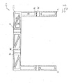
- Fig. 1 shows by way of example in a plan view, ie front view, a heat exchanger assembly 100 with an exemplary illustrated heat exchanger 10 in the form of a coolant radiator, which is presently designed as a so-called down-flow cooler.
- the heat exchanger assembly 100 has a mounting frame 1, which has an extruded aluminum U-profile 3 with a forehead 5 and two legs 7, 9 for fastening the heat exchanger 10 to a vehicle.
- the term "extruded” is used here as a synonym for "extruded”.
- the heat exchanger shown schematically has a block with a core for the separate and heat exchanging guidance of the first fluid to be cooled 11 - in the present case in the form of coolant - and the second cooling fluid 12 - in the present case in the form of cooling air.
- a number of the coolant flow-through flow channels 13 are provided in the core, which are arranged in a housing 15.
- the coolant flowing in the flow channels 13 releases its excess heat to the flow channels 13 and the cooling fins 17 arranged between the flow channels.
- the core arrangement of flow channels 13 and cooling fins 17 is impinged in the housing by cooling air 12, so that the cooling air 12 can absorb the excess heat of the coolant.
- the first fluid 11 in the form of coolant is presently fed through a feed port 19, first an input-side box 21, which is also referred to as a tank.
- the box 21 in this case has a collection and diffuser effect, so that the coolant uniformly on the held in a bottom not shown cross-sections of the flow channels 13th is distributed and can flow through to an output-side box 23, from which the coolant is discharged via an outlet port 25 into the cooling circuit.
- a mounting frame 1 - below Fig. 2 as 1.1, at Fig. 3 as 1.2 and at Fig. 4 referred to as 1.3 - are explained in more detail with reference to the section line A - A, the mounting frame 1 is in Fig. 1 connected via screw 27 to the heat exchanger 10 and thus holds the heat exchanger.
- the mounting frame 1 itself is fastened to the vehicle via a screw-fastening means 29, in the present case a sheet metal.
- the vehicle is not explained in detail here.
- the heat exchanger assembly 100 in the in Fig. 1 The view shown is as a front view of a radiator grille of a vehicle.
- heat exchangers 10 may need and in their actual use much more flow channels 13 in the form of tubes and ribs 17 as shown here.
- retaining ring of the flow channels 13 in the form of a bottom 14 is in Fig. 2 shown schematically.
- sectional view A - A is below the bottom 14 of the output side box 23rd
- first embodiment of a mounting frame 1.1 can as a mounting frame 1 of Fig. 1 be provided in a heat exchange assembly 100.
- the heat exchanger 10 with housing 15, bottom 14 and flow channels 13 held by ribs 17 are shown once again.
- the core formed by flow channels 13 and ribs 17 is also held in position with a side part 18 in position.
- the mounting frame 1.1 has an aluminum U-profile 3.1 with a front side 5 and two legs 7, 9.
- the mounting frame 1.1 is held by a fastening means 31 on the vehicle.
- the fastening means 31 is formed from a fastening plate 35 attached to the U-profile 3.1 by means of a screw connection 33.
- the mounting plate 35 has an angular shape and has in one leg of the angular geometry an opening 37 through which a connecting means for screwing to a vehicle part can be passed.
- the U-profile 3.1 is, as explained, formed in the form of a fully U-shaped extruded aluminum U-profile.
- the extrusion of the U-profile 3.1 is carried out with the structure of the U-profile 3.1.
- the structure is presently formed on the front side 5 in three chambers by means of crossed diagonal tongues 53, each of which subdivides a chamber into cavities 51.
- the structure is formed in the legs 7, 9 respectively by uncrossed Diagonalver 73, 93, which divides the two chambers into cavities 71, 91.
- the chambers themselves are separated by solid material sections 81.
- the Votimaterialabête 81 each carry a bore 83 for receiving a further fastening means 80 in the form of a screw connection.
- the mounting frame 1.1 is present along the axial arrangement of a heat exchanger 10 at the level of a box 21, 23, as in Fig. 1 is shown attached and secured with the fastener 80 at the cost 21, 23.
- the U-profile 3.1 is equipped with wall thicknesses which are above wall thicknesses of steel frames.
- the outer wall thickness of the U-profile 3.1 - for example, at the points of reference numerals 7, 9 or other locations of the legs 7, 9 - 2 mm to 4 mm.
- the supporting structure, in particular the diagonal cables 53, 93, 73 may possibly be equipped with a thinner wall thickness in the range between 2 mm to 4 mm.
- the formation of the structure in the aforementioned chambers to form the cavities 51, 71, 91 leads to a stiffening structure structure, which makes the strength of the mounting frame 1.1 despite material reduction and aluminum construction material sufficient.
- the need for training of the structure structure on the special fürsunfallsfall, in particular the static or dynamic requirements of a specific use case, is possible in the advantage of a steel construction material.
- Fig. 3 shows a further preferred embodiment of a mounting frame 1.2 with an extruded aluminum U-profile 3.2.
- Fig. 2 shows the mounting frame 1.2 without heat exchanger 10. Nevertheless, the mounting frame 1.2 instead of in Fig. 1 shown mounting frame 1 are used to form a heat exchanger assembly 100.
- the bushings 85 shown in the solid material sections 81 serve to receive a screw connection 80, as they are in Fig. 2 is shown.
- the structure of the aluminum U-section 3.2 is present differently designed than in the aluminum U-section 3.1 of Fig. 2 , In the present case, only uncrossed diagonal trains 54 for forming cavities 56 are arranged on the front side 5, the cavities 56 in turn being formed by division of the chambers separated by solid material sections 81. In the thighs 7, 9 are provided in the separated by Vollmateriaiabête 81 chambers 58 no diagonal trains.
- This embodiment of an aluminum U-profile 3.2 is simpler than that of the aluminum U-profile 3.1 and designed for requirements with lower rigidity
- Fig. 4 shows a third embodiment of a mounting frame 1.3 with an extruded aluminum U-profile 3.3 that the Fig. 3 comes closest.
- the legs 7, 9 of the U-profile have present no diagonal trains.
- the brow 5 of the U-profile is presently formed with a chamber which is divided in each case by a Tragyak 52 in three cavities 59.
- the central cavity is formed in the form of a coolant channel 60, via which a first fluid 11 in the form of coolant through an opening 61 to the box 21, 25 of the heat exchanger 10 can be performed.
- the box 21, 25 is pressed into the U-profile 3.3 and sealed in the region of the opening 61 with a seal 63 for sealing the opening 61.
- a mounting frame 1, 1.1, 1.2, 1.3 has been explained for fastening a heat exchanger 10, in particular on a vehicle, which has a U-shaped profile 3, 3.1, 3.2, 3.3 with a forehead 5 and two legs 7, 9 has.
- fastening means 31, 80 for the heat exchanger 10 and / or the profile 3 is provided.
- the profile 3 in the form of a hollow profile made of aluminum and with a stiffening-acting structure for the formation of internal cavities 51, 56, 59, 71, 91 of the hollow profile is formed.
Landscapes
- Engineering & Computer Science (AREA)
- Mechanical Engineering (AREA)
- Chemical & Material Sciences (AREA)
- Combustion & Propulsion (AREA)
- Transportation (AREA)
- Physics & Mathematics (AREA)
- Thermal Sciences (AREA)
- General Engineering & Computer Science (AREA)
- Body Structure For Vehicles (AREA)
- Heat-Exchange Devices With Radiators And Conduit Assemblies (AREA)
Abstract
Description
Die Erfindung betrifft einen Befestigungsrahmen gemäß dem Oberbegriff des Anspruchs 1. Die Erfindung betrifft weiter eine Wärmetauscheranordnung mit einem Wärmetauscher und einem solchen Befestigungsrahmen. Weiter betrifft die Erfindung ein Fahrzeug, insbesondere ein Nutzfahrzeug, mit einer solchen Wärmetauscheranordnung.The invention relates to a mounting frame according to the preamble of claim 1. The invention further relates to a heat exchanger assembly with a heat exchanger and such a mounting frame. Furthermore, the invention relates to a vehicle, in particular a commercial vehicle, with such a heat exchanger assembly.
Bei Fahrzeugen, insbesondere bei Nutzkraftfahrzeugen, besteht aufgrund der hohen Antriebsleistungen ein vergleichsweise hoher Kühlbedarf für die eingesetzten Arbeitsfluide. Dies kann beispielsweise ein Ladefluid einer Brennkraftmaschine, wie z.B. ein Abgas oder eine Ladeluft, sein. Dazu wird regelmäßig ein Wärmetauscher in Form eines Ladefluid-Wärmetauschers, beispielsweise ein Gaskühler, eingesetzt, Insbesondere besteht auch ein erhöhter Rückkühlbedarf für Kühlmittel oder Kältemittel oder dergleichen. Dazu ist regelmäßig ein Wärmetauscher in Form eines Kühlmittelkühlers oder dergleichen vorgesehen. Solche und andere Wärmetauscher, insbesondere Kühlmodule, können relativ schwer werden - dementsprechend sind sie durch vergleichsweise aufwändige Elemente am Fahrzeug befestigt. Die Befestigungselemente müssen nicht nur das Eigengewicht des Wärmetauschers tragen, sondern auch dazu ausgelegt sein, dynamischen Beanspruchungen, wie beispielsweise Erschütterungen oder Vibrationen, standzuhalten. Für die Befestigung eines Kühlmittelkühlers haben sich beispielsweise U-förmige Profile aus Stahl bewährt, die zur Vermeidung von Korrosion lackiert werden. Wünschenswert wäre ein erhöhter Korrosionsschutz bei einem geeigneten Befestigungselement für einen Wärmetauscher. Grundsätzlich könnte dazu ein besonders korrosionsresistenter Stahl zum Einsatz kommen. Dieser erweist sich jedoch als vergleichsweise kostenaufwändig hinsichtlich Material und Herstellungsaufwand.In vehicles, especially commercial vehicles, there is a relatively high cooling demand for the working fluids used due to the high drive power. This can be, for example, a charging fluid of an internal combustion engine, such as an exhaust gas or a charge air. For this purpose, a heat exchanger in the form of a charge-fluid heat exchanger, for example a gas cooler, is used regularly. In particular, there is also an increased need for recooling for coolant or refrigerant or the like. For this purpose, a heat exchanger in the form of a coolant radiator or the like is regularly provided. Such and other heat exchangers, in particular Cooling modules, can be relatively heavy - accordingly, they are attached by comparatively complex elements on the vehicle. The fasteners must not only support the dead weight of the heat exchanger, but also be designed to withstand dynamic loads, such as shock or vibration. For the attachment of a coolant radiator, for example, U-shaped profiles made of steel, which are painted to prevent corrosion. It would be desirable to have increased corrosion protection in a suitable fastener for a heat exchanger. In principle, a particularly corrosion-resistant steel could be used for this purpose. However, this proves to be relatively expensive in terms of material and manufacturing costs.
An dieser Stelle setzt die Erfindung an, deren Aufgabe es ist, eine Vorrichtung anzugeben, die zur Befestigung eines Wärmetauschers, insbesondere an einem Fahrzeug, vorteilhaft ausgelegt ist und die darüber hinaus einen erhöhten Korrosionsschutz aufweist. Die Vorrichtung soll insbesondere in der Lage sein, den statischen und dynamischen mechanischen Beanspruchungen bei der Halterung eines Wärmetauschers zu genügen.At this point, the invention begins, whose task is to provide a device which is designed to attach a heat exchanger, in particular on a vehicle, advantageous and which also has an increased corrosion protection. The device should in particular be able to satisfy the static and dynamic mechanical stresses in the mounting of a heat exchanger.
Die Aufgabe betreffend die Vorrichtung wird durch die Erfindung mittels einem Befestigungsrahmen der eingangs genannten Art gelöst, bei dem erfindungsgemäß die Merkmale des kennzeichnenden Teils des Anspruchs 1 vorgesehen sind.The object concerning the device is achieved by the invention by means of a mounting frame of the type mentioned, in which the features of the characterizing part of claim 1 are provided according to the invention.
Die Erfindung geht von der Überlegung aus, dass sich ein eingangs genanntes U-Profil grundsätzlich eignet, um einen Wärmetauscher zu befestigen. Weiter hat die Erfindung erkannt, dass sowohl aufwändige korrosionshemmende Lackierungen als auch korrosionshemmende Stähle kosteneinsparend ersetzt werden können durch ein geeignetes Aluminiummaterial. Die Erfindung hat erkannt, dass sich das U-Profil des Befestigungsrahmens mit Stirn und zwei Schenkeln vorteilhaft in Form eines U-Profils aus Aluminium bilden lässt. Dadurch sind die Korrosionsprobleme bei einem Befestigungsrahmen praktisch beseitigt. Um darüber hinaus eine, einem Stahlrahmen vergleichbare, statische und dynamische Stabilität zu gewährleisten, hat die Erfindung darüber hinaus erkannt, dass das Profil in Form eines Hohlprofils mit einem versteifend wirkenden Tragwerk zur Bildung von innenliegenden Hohlräume des Hohlprofils zu bilden. Dies führt nicht nur zu einer, bedarfsgerecht und mit hoher Sicherheitsmarge auslegbaren, dynamischen und statischen Stabilität des Profils, Vielmehr lässt sich die Stabilität speziell - beispielsweise auf ein Vibrationsspektrum eines Fahrzeugs - anpassen. Darüber hinaus ist durch die Bildung des Profils in Form eines Hohlprofils mit innenliegenden Hohlräume ein Materialbedarf vergleichsweise gering gehalten. Neben dem Werkstoff Aluminium führen Hohlräumen darüber hinaus zu einer erheblichen Gewichtseinsparung. Entsprechend ist ein Kostenaufwand zur Herstellung des Befestigungsrahmens vergleichsweise gering gegenüber üblicherweise vorgesehenen Stahlrahmen.The invention is based on the consideration that a U-profile mentioned in principle is suitable to secure a heat exchanger. Next, the invention has recognized that both costly corrosion-inhibiting coatings and corrosion-inhibiting steels can be cost-effectively replaced by a suitable aluminum material. The invention has recognized that the U-profile of the mounting frame with Forehead and two legs can be advantageous in the form of a U-profile made of aluminum. As a result, the corrosion problems in a mounting frame are virtually eliminated. Moreover, in order to ensure a static and dynamic stability comparable to a steel frame, the invention has moreover recognized that the profile in the form of a hollow profile with a supporting structure acting in a stiffening fashion forms the formation of internal cavities of the hollow profile. This not only leads to a dynamic and static stability of the profile which can be interpreted as required and with a high margin of safety. Rather, the stability can be specifically adapted, for example to a vibration spectrum of a vehicle. In addition, a material requirement is kept comparatively low by the formation of the profile in the form of a hollow profile with internal cavities. In addition to the material aluminum cavities also lead to a significant weight savings. Accordingly, a cost for the production of the mounting frame is comparatively small compared to commonly provided steel frame.
Vorteilhafte Weiterbildungen der Erfindung sind den Unteransprüchen zu entnehmen und geben im Einzelnen vorteilhaften Möglichkeiten an, das oben erläuterte Konzept im Rahmen der Aufgabenstellung sowie hinsichtlich weiterer Vorteile zu realisieren.Advantageous developments of the invention can be found in the dependent claims and indicate in detail advantageous possibilities to realize the above-described concept within the scope of the problem as well as with regard to further advantages.
In einer besonders vorteilhaften Weiterbildung ist das Profil in Form eines mit dem Tragwerk extrudierten Aluminium-U-Profils gebildet. Die Extrusion des Aluminium-U-Profils lässt sich mit dem Tragwerk vergleichsweise einfach und in hoher Stückzahl sowie in vergleichsweise kurzer Zeit realisieren. Alternativ oder zusätzlich kann das Profil auch in Form eines abgekanteten Aluminium-U-Profils mit dem Tragwerk in geprägter Form gebildet sein, Mit anderen Worten kann das Profil insgesamt als abgekantetes Aluminium-U-Profil mit dem Tragwerk in geprägter Form hergestellt sein. Es kann jedoch auch bei einem extrudierten Aluminium-U-Profil bei Bedarf eine weitere Umformung vorgenommen werden, beispielsweise das Tragwerk in geprägter Form gebildet sein.In a particularly advantageous embodiment, the profile is formed in the form of an extruded with the supporting structure aluminum U-profile. The extrusion of the aluminum U-profile can be relatively easily and in large numbers and in a relatively short time realize with the structure. Alternatively or additionally, the profile can also be formed in the form of a bent aluminum U-profile with the structure in embossed form, in other words, the profile can be made in total as a bent aluminum U-profile with the structure in embossed form. However, it may also in an extruded aluminum U-profile, if necessary, a further transformation be made, for example, the structure be formed in embossed form.
Eine Wandstärke des Profils beträgt vorteilhaft zwischen 2 mm bis 16 mm. Dies betrifft insbesondere eine Außenwandstärke des Profils. Die Wandstärke bzw. Außenwandstärke beträgt besonders vorteilhaft zwischen 4 mm bis 8 mm. Es hat sich gezeigt, dass diese Wandstärken bereits ausreichend sein, um selbst bei Verwendung eines Aluminiumwerkstoffs gemäß dem Konzept der Erfindung eine ausreichende Stabilität für den Befestigungrahmen zur Verfügung steht.A wall thickness of the profile is advantageously between 2 mm to 16 mm. This relates in particular to an outer wall thickness of the profile. The wall thickness or outer wall thickness is particularly advantageous between 4 mm to 8 mm. It has been found that these wall thicknesses are already sufficient to provide sufficient stability for the mounting frame even when using an aluminum material according to the concept of the invention.
Je nach Bedarf kann die Wandstärke des Tragwerks zwischen 2 mm bis 6 mm gewählt werden. Grundsätzlich kann, wie sich mit Vorteil gezeigt hat, die Wandstärke des Tragwerks geringer gewählt werden als die Außenwandstärke. Beispielsweise kann die Wandstärke des Tragwerks zwischen 2 mm bis 4 mm betragen.Depending on requirements, the wall thickness of the structure can be chosen between 2 mm to 6 mm. In principle, as has been shown to advantage, the wall thickness of the structure can be selected lower than the outer wall thickness. For example, the wall thickness of the structure can be between 2 mm to 4 mm.
Mit Vorteil versehen kann das Profil wenigstens eine Verbindungsdurchführung zur Verbindung des Profils mit dem Wärmetauscher aufweisen. Die Verbindungsdurchführung ist in besonders vorteilhafter Weise für eine Schraubverbindung oder eine Nietverbindung ausgelegt. Es hat sich als besonders vorteilhaft erwiesen, dass eine Verbindungsdurchführung vollständig in einem Vollmaterialabschnitt des Profils angeordnet ist. Dadurch ist gewährleistet, dass selbst bei hohem Anzugsmoment einer Schraubverbindung oder einer Nietverbindung oder einer sonstigen Verbindung ein unerwünschtes Zusammenpressen oder eine unerwünschte Spannungsbelastung des Befestigungsrahmens durch das Vollmaterial unterbunden wird. Insbesoridere wird ein Einleiten der Befestigungskräfte in das Tragwerk durch das Vollmaterial vermieden bzw. voll aufgenommen. Somit kann das Tragwerk des Profils vollständig zur Stabilisierung desselben ausgelegt und genutzt werden.Provided with advantage, the profile can have at least one connecting bushing for connecting the profile to the heat exchanger. The connecting bushing is designed in a particularly advantageous manner for a screw or a rivet. It has proved to be particularly advantageous that a connecting bushing is arranged completely in a solid material section of the profile. This ensures that even at high torque of a screw or a rivet or other connection an undesirable compression or undesirable stress load of the mounting frame is prevented by the solid material. Insbesoridere a introduction of the fastening forces in the structure by the solid material is avoided or fully absorbed. Thus, the structure of the profile can be completely designed and used to stabilize the same.
Im Rahmen einer bevorzugten Variante kann das Tragwerk fachwerkartig mit einer Anzahl von Kammern ausgeführt sein, wobei eine Kammer grundsätzlich einen Tragwerkzug aufweisen muss. Die Kammer kann auch einen gekreuzten oder ungekreuzten Diagonalzug aufweisen. Als verteilhaft hat sich beispielsweise erwiesen, dass die Stirn des Profils einen gekreuzten Diagonalzug aufweist und/oder ein Schenkel des Profils einen ungekreuzten Diagonalzug aufweist. Insbesondere ist es vorteilhaft, die Stirn des Profils lediglich mit gekreuzten Diagonalzügen zu vergehen. Es ist auch vorteilhaft, einen Schenkel des Profils lediglich mit ungekreuzten Diagonalzügen zu versehen. Diese Fachwerkarten haben sich als besonders leicht herstellbar, insbesondere im Rahmen einer Extrusion, erwiesen und tragen den Belastungsanforderungen des Befestigungsrahmens im Allgemeinen Rechnung.In the context of a preferred variant, the structure can be executed like a truss with a number of chambers, wherein a chamber must always have a structural train. The chamber may also have a crossed or uncrossed diagonal train. For example, it has proven to be distributive that the end of the profile has a crossed diagonal tension and / or one leg of the profile has an uncrossed diagonal tension. In particular, it is advantageous to pass the forehead of the profile only with crossed Diagonalzügen. It is also advantageous to provide one leg of the profile only with uncrossed diagonal tongues. These truss types have proven to be particularly easy to produce, especially in the context of extrusion, and take into account the load requirements of the mounting frame in general.
Im Rahmen einer besonders vorteilhaften Weiterbildung wurde erkannt, dass ein Hohlraum des Profils funktionell genutzt werden kann. Die Weiterbildung sieht vor, dass wenigstens eine Kammer und/oder ein Hohlraum des Profils als ein Kanal zur Führung eines wärmetauschenden Fluids ausgebildet sein kann. Insbesondere weist der Kanal eine Öffnung zur Überführung des wärmetauschenden Fluids zu einem befestigbaren Wärmetauscher auf. Dies führt dazu, dass eine Zuleitung von wärmetauschendem Fluid zum Wärmetauscher durch den Befestigungsrahmen aufgenommen werden kann bzw. durch den Kanal des Befestigungsrahmens ausgeführt werden kann. Der Befestigungsrahmen dient damit nicht nur zur Befestigung des Wärmetauschers, sondern darüber hinaus als Zuleitung von wärmetauschendem Fluid zum Wärmetauscher. Die Öffnung ist vorteilhaft abgedichtet. Insgesamt kann dadurch eine sichere Überführung des wärmetauschenden Fluids gewährleistet werden.As part of a particularly advantageous development has been recognized that a cavity of the profile can be used functionally. The development provides that at least one chamber and / or a cavity of the profile can be formed as a channel for guiding a heat exchanging fluid. In particular, the channel has an opening for transferring the heat-exchanging fluid to an attachable heat exchanger. As a result, a supply of heat-exchanging fluid to the heat exchanger can be accommodated by the attachment frame or can be carried out through the channel of the attachment frame. The mounting frame thus serves not only for fastening the heat exchanger, but also as a supply of heat exchanging fluid to the heat exchanger. The opening is advantageously sealed. Overall, this ensures a safe transfer of the heat exchanging fluid.
Entsprechend dem Konzept der Erfindung führt dies zur Erfüllung der Aufgabe auch auf eine Wärmetauscheranordnung mit einem Wärmetauscher und einem Befestigungsrahmen gemäß dem oben erläuterten Konzept bzw. gemäß einer oder mehrerer der vorhergehend erläuterten Weiterbildungen.According to the concept of the invention this leads to the fulfillment of the task also to a heat exchanger assembly with a heat exchanger and a mounting frame according to the above-described concept or according to one or more of the previously explained developments.
Der Wärmetauscher der Wärmetauscheranordnung ist insbesondere zum Wärmetausch zwischen einem ersten Fluid einerseits und einem zweiten Fluid andererseits ausgebildet. Der Wärmetauscher weist zum einen einen Block auf, der mit einem Kern zur voneinander getrennten und wärmetauschenden Führung des ersten und zweiten Fluids versehen ist. Der Kern hat eine Anzahl von dem ersten Fluid durchströmbare Strömungskanäle und ist in einen die Strömungskanäle aufnehmenden, von dem zweiten Fluid durchströmbaren Gehäuseinneren eines Gehäuses angeordnet. Weiter weist der Wärmetauscher wenigstens einen Kasten zur Leitung des ersten Fluids von oder zu den Strömungskanälen auf.The heat exchanger of the heat exchanger arrangement is designed in particular for the heat exchange between a first fluid on the one hand and a second fluid on the other. The heat exchanger has on the one hand a block which is provided with a core for the separate and heat exchanging guidance of the first and second fluid. The core has a number of flow passages through which the first fluid can flow and is arranged in a housing interior of a housing receiving the flow passages and permeable by the second fluid. Furthermore, the heat exchanger has at least one box for conducting the first fluid from or to the flow channels.
Der Kasten - auch als Tank bezeichnet - dient insbesondere zur vergleictlmäßigenden Strömungszuführung der Strömung des ersten Fluids zu den Strömungskanälen. Dazu kann der Kasten beispielsweise in Form eines Diffusors ausgebildet sein.The box - also referred to as a tank - is used in particular for comparison flow-reducing flow of the flow of the first fluid to the flow channels. For this purpose, the box may be formed, for example in the form of a diffuser.
Es hat sich gezeigt, dass vorteilhaft ein Kasten des Wärmetauschers mittels eines Befestigungsmittels des Befestigungsrahmens am Befestigungsrahmen befestigt ist. Diese Befestigungsart von Wärmetauscher und Befestigungsrahmen hat sich als besonders stabil erwiesen.It has been found that advantageously a box of the heat exchanger is fastened by means of a fastening means of the mounting frame on the mounting frame. This type of fastening of heat exchanger and mounting frame has proven to be particularly stable.
Der Wärmetauscher der Wärmetauscheranordnung findet bevorzugt Verwendung als ein Ladefluid-Wärmetauscher, zur Kühlung eines Ladefluids in einem Ladefluidsystem einer Brennkraftmaschine eines Kraftfahrzeugs. Dies kann beispielsweise ein Abgaswärmetauscher oder ein Ladeluftwärmetauscher sein. Dabei ist das erste Fluid regelmäßig als ein Abgas und/oder eine Ladeluft gebildet, das zweite Fluid entsprechend als ein Kühlmittel oder dergleichen.The heat exchanger of the heat exchanger arrangement is preferably used as a charging fluid heat exchanger for cooling a charging fluid in a charging fluid system of an internal combustion engine of a motor vehicle. This can be, for example, an exhaust gas heat exchanger or a charge air heat exchanger. In this case, the first fluid is regularly formed as an exhaust gas and / or a charge air, the second fluid accordingly as a coolant or the like.
Darüber hinaus hat sich das Konzept der Erfindung als besonders bevorzugt zur Verwendung bei einem Wärmetauscher als Kälte- oder Kühlmittelkühler und/oder Kälte- oder Kühlmittelkondensator in einem Kälte- oder Kühlmittelkreislauf erwiesen, beispielsweise in einem Kühimittelkreislauf eines Kraftfahrzeugs und/oder einer Klimaanlage eines Kraftfahrzeugs. Dabei dienen die Strömungskanäle entsprechend zur Führung eines ersten Fluids in flüssiger Form, insbesondere zur Führung von Kühlmittel und/oder Kältemittel. Das zweite Fluid ist entsprechend in gasförmiger Form gebildet, insbesondere in Form von Kühlluft oder dergleichen.In addition, the concept of the invention has proven to be particularly preferred for use in a heat exchanger as a refrigerant or coolant cooler and / or refrigerant or refrigerant condenser in a refrigerant or refrigerant circuit, for example in a coolant circuit of a motor vehicle and / or an air conditioning system of a motor vehicle. The flow channels serve accordingly to guide a first fluid in liquid form, in particular for the guidance of coolant and / or refrigerant. The second fluid is accordingly formed in gaseous form, in particular in the form of cooling air or the like.
Grundsätzlich lässt sich das Konzept der Erfindung auch anwenden auf andere Wärmetauscher, beispielsweise auf Ölkühler, insbesondere zur Kühlung von Motoröl und/oder Getriebeöl oder dergleichen.In principle, the concept of the invention can also be applied to other heat exchangers, for example to oil coolers, in particular for cooling engine oil and / or gear oil or the like.
Ausführungsbeispiele der Erfindung werden nun nachfolgend anhand der Zeichnung beschrieben. Diese soll die Ausführungsbeispiele nicht notwendigerweise maßstäblich darstellen, vielmehr ist die Zeichnung, wo zur Erläuterung dienlich, in schematisierter und/oder leicht verzerrter Form ausgeführt. Im Hinblick auf Ergänzungen der aus der Zeichnung unmittelbar erkennbaren Lehren wird auf den einschlägigen Stand der Technik verwiesen. Dabei ist zu berücksichtigen, dass vielfältige Modifikationen und Änderungen betreffend die Form und das Detail einer Ausführungsform vorgenommen werden können, ohne von der allgemeinen Idee der Erfindung abzuweichen. Die in der Beschreibung, in der Zeichnung sowie in den Ansprüchen offenbarten Merkmale der Erfindung können sowohl einzeln als auch in beliebiger Kombination für die Weiterbildung der Erfindung wesentlich sein. Zudem fallen in den Rahmen der Erfindung alle Kombinationen aus zumindest zwei der in der Beschreibung, der Zeichnung und/oder den Ansprüchen offenbarten Merkmale. Die allgemeine Idee der Erfindung ist nicht beschränkt auf die exakte Form oder das Detail der im folgenden gezeigten und beschriebenen bevorzugten Ausführungsform oder beschränkt auf einen Gegenstand, der eingeschränkt wäre im Vergleich zu dem in den Ansprüchen beanspruchten Gegenstand. Bei angegebenen Bemessungsbereichen sollen auch innerhalb der genannten Grenzen liegende Werte als Grenzwerte offenbart und beliebig einsetzbar und beanspruchbar sein. Der Einfachheit halber sind nachfolgend für identische oder ähnliche Teile oder Teile mit identischer oder ähnlicher Funktion gleiche Bezugszeichen verwendet.Embodiments of the invention will now be described below with reference to the drawing. This is not necessarily to scale the embodiments, but the drawing, where appropriate for explanation, executed in a schematized and / or slightly distorted form. With regard to additions to the teachings directly recognizable from the drawing reference is made to the relevant prior art. It should be noted that various modifications and changes may be made in the form and detail of an embodiment without departing from the general idea of the invention. The disclosed in the description, in the drawing and in the claims features of the invention may be essential both individually and in any combination for the development of the invention. In addition, all combinations of at least two of the features disclosed in the description, the drawings and / or the claims fall within the scope of the invention. The general idea of the invention is not limited to the exact form or detail of those shown and described below preferred embodiment or limited to an object that would be limited compared to the claimed in the claims subject matter. For the given design ranges, values within the stated limits should also be disclosed as limit values and be arbitrarily usable and claimable. For simplicity, the same reference numerals are used below for identical or similar parts or parts with identical or similar function.
Vorteilhaft ist ein Fahrzeug, vorzugsweise Nutzkraftfahrzeug, mit einer Wärmetauscheranordnung, die über ein Befestigungsmittel des Befestigungsrahmens am Fahrzeug festgemacht ist.Advantageously, a vehicle, preferably utility vehicle, with a heat exchanger assembly which is fastened to the vehicle via a fastening means of the mounting frame.
Weitere Vorteile, Merkmale und Einzelheiten der Erfindung ergeben sich aus der nachfolgenden Beschreibung der bevorzugten Ausführungsbeispiele sowie anhand der Zeichnung; diese zeigt in:
- Fig. 1:
- eine schematische Draufsicht auf eine Wärmetauscheranordnung mit einem Wärmetauscher und einem Befestigungsrahmen gemäß einer bevorzugten Ausführungsform, wobei der Wärmetauscher in Form eines Kühlmittelkühlers für Motorkühlmittel gebildet ist;
- Fig. 2:
- eine erste weitere bevorzugte Ausführungsform einer Wärmetau- scheranordnung entlang des Schnitts A - A der
Fig. 1 in schemati- scher Darstellung; - Fig. 3:
- eine zweite Ausführungsform eines Befestigungsrahmens wie sie bei einer Wärmetauscheranordnung der
Fig. 2 oderFig. 1 verwendet werden kann; - Fig. 4:
- eine dritte Ausführungsform eines Befestigungsrahmens in schema- tischer Darstellung, wie sie beispielsweise für eine Wärmetauscher- anordnung der
Fig. 2 ,Fig. 1 verwendbar ist und der zusätzlich ei- nem Hohlraum des Befestigungsrahmens als Kühlmittelführung nutzt.
- Fig. 1:
- a schematic plan view of a heat exchanger assembly having a heat exchanger and a mounting frame according to a preferred embodiment, wherein the heat exchanger is formed in the form of a coolant radiator for engine coolant;
- Fig. 2:
- a first further preferred embodiment of a Wärmetau- shear arrangement along the section A - A of
Fig. 1 in a schematic representation; - 3:
- a second embodiment of a mounting frame as in a heat exchanger assembly of
Fig. 2 orFig. 1 can be used; - 4:
- a third embodiment of a mounting frame in a schematic representation, as for example for a heat exchanger arrangement of
Fig. 2 .Fig. 1 is usable and additionally uses a cavity of the mounting frame as a coolant guide.
Der schematisch dargestellte Wärmetauscher hat einen Block mit einem Kern zur voneinander getrennten und wärmetauschenden Führung des zu kühlenden ersten Fluids 11 - vorliegend in Form von Kühlmittel - und des zweiten kühlenden Fluids 12 - vorliegend in Form von Kühlluft. Dazu sind im Kern eine Anzahl von dem Kühlmittel durchströmbare Strömungskanäle 13 vorgesehen, die in einem Gehäuse 15 angeordnet sind. Das in den Strömungskanälen 13 strömende Kühlmittel gibt seine überschüssige Wärme an die Strömungskanäle 13 und die, zwischen den Strömungskanälen angeordneten, Kühlrippen 17 ab. Die Kernanordnung aus Strömungskanälen 13 und Kühlrippen 17 wird im Gehäuse durch Kühlluft 12 angeströmt, sodass die Kühlluft 12 die überschüssige Wärme des Kühlmittels aufnehmen kann. Das erste Fluid 11 in Form von Kühlmittel wird vorliegend durch einen Zuführstutzen 19 zunächst einem eingangsseitigen Kasten 21 zugeführt, welcher auch als Tank bezeichnet wird. Der Kasten 21 hat vorliegend eine Sammel- und Diffusorwirkung, sodass das Kühlmittel gleichmäßig auf die in einem nicht näher dargestellten Boden gehaltenen Querschnitte der Strömungskanäle 13 verteilt wird und diese durchströmen kann bis zu einem ausgangsseitigen Kasten 23, von dem aus das Kühlmittel über einen Ausgangsstutzen 25 in den Kühlkreislauf abgeführt wird.The heat exchanger shown schematically has a block with a core for the separate and heat exchanging guidance of the first fluid to be cooled 11 - in the present case in the form of coolant - and the second cooling fluid 12 - in the present case in the form of cooling air. For this purpose, a number of the coolant flow-through flow channels 13 are provided in the core, which are arranged in a housing 15. The coolant flowing in the flow channels 13 releases its excess heat to the flow channels 13 and the cooling
Erste, zweite und dritte Ausführungsformen eines Befestigungsrahmens 1 - im Folgenden bei
Im Folgenden werden für identische oder ähnliche Teile sowie Teile ähnlicher oder identischer Funktion gleiche Bezugszeichen verwendet. Darüber hinaus sind sämtliche Darstellungen, insbesondere die Darstellung der Anzahl von Rohren und Rippen, rein schematisch gemeint, Wärmetauscher 10 können bedarfsgerecht und in ihrer konkreten Verwendung sehr viel mehr Strömungskanäle 13 in Form von Rohren und Rippen 17 aufweisen als hier gezeigt. Die in Bezug auf
Darüber hinaus ist vorliegend die Anordnung von Befestigungsmitteln 29 oder der Schraubverbindungen 27 abhängig von der tatsächlichen Verwendung und dem konkreten Bauraumbedarf beim Einbau der Wärmetauscheranordnung 100. Insofern können diese, je nach Befestigungsart, Befestigungsnotwendigkeit und Bauraumverfügbarkeit, unterschiedlich und verwendungsangepasst erfolgen. Die vorliegend symbolisch dargestellten Ausführungsbeispiele sind rein exemplarisch zu sehen.Moreover, in the present case, the arrangement of fastening means 29 or the screw 27 depending on the actual use and the specific space requirement when installing the
Die in
Der Befestigungsrahmen 1.1 gemäß der ersten Ausführungsform weist ein Aluminium-U-Profil 3.1 mit einer Stirnseite 5 sowie zwei Schenkeln 7, 9 auf. Der Befestigungsrahmen 1.1 ist über ein Befestigungsmittel 31 am Fahrzeug gehalten. Das Befestigungsmittel 31 ist vorliegend aus einem am U-Profil 3.1 mittels einer Schraubverbindung 33 angebrachten Befestigungsblech 35 gebildet. Das Befestigungsblech 35 hat Winkelform und hat in einem Schenkel der Winkelfom eine Öffnung 37, durch die ein Verbindungsmittel zum Anschrauben an ein Fahrzeugteil hindurchgeführt werden kann.The mounting frame 1.1 according to the first embodiment has an aluminum U-profile 3.1 with a front side 5 and two
Das U-Profil 3.1 gemäß der ersten Ausführungsform ist, wie erläutert, in Form eines vollständig in U-Form extrudierten Aluminium-U-Profils gebildet. Die Extrusion des U-Profils 3.1 erfolgt dabei mit dem Tragwerk des U-Profils 3.1. Das Tragwerk ist vorliegend auf der Stirnseite 5 in drei Kammern mittels gekreuzten Diagonalzügen 53 gebildet, welche jeweils eine Kammer in Hohlräume 51 unterteilt. Das Tragwerk ist in den Schenkeln 7, 9 jeweils durch ungekreuzte Diagonalzüge 73, 93 gebildet, welche die jeweils zwei Kammern in Hohlräume 71, 91 unterteilt. Die Kammern selbst werden durch Vollmaterialabschnitte 81 getrennt. Die Votimaterialabschnitte 81 tragen jeweils eine Bohrung 83 zur Aufnahme eines weiteren Befestigungsmittels 80 in Form einer Schraubverbindung. Der Befestigungsrahmen 1.1 ist vorliegend entlang der axialen Anordnung eines Wärmetauschers 10 auf Höhe eines Kastens 21, 23, wie er in
Insgesamt führt die Bildung des Tragwerks in den zuvor erwähnten Kammern unter Bildung der Hohlräume 51, 71, 91 zu einer versteifend wirkenden Tragwerksstruktur, welche die Festigkeit des Befestigungsrahmens 1.1 trotz Materialreduktion und Aluminiumbaustoff ausreichend gestaltet. Darüber hinaus ist im Vorteil zu einem Stahlbaustoff die bedarfsgerechte Ausbildung der Tragwerksstruktur auf den speziellen Verwendunssfall, insbesondere die statischen oder dynamischen Anforderungen eines speziellen Verwendungsfalls, möglich.Overall, the formation of the structure in the aforementioned chambers to form the cavities 51, 71, 91 leads to a stiffening structure structure, which makes the strength of the mounting frame 1.1 despite material reduction and aluminum construction material sufficient. In addition, the need for training of the structure structure on the special Anwendungsunfallsfall, in particular the static or dynamic requirements of a specific use case, is possible in the advantage of a steel construction material.
Zusammenfassend ist ein Befestigungsrahmen 1, 1.1, 1.2, 1.3 zur Befestigung eines Wärmetauschers 10, insbesondere an einem Fahrzeug, erläutert worden, der eine mit einem Profil gebildete U-Form 3, 3.1, 3.2, 3.3 mit einer Stirn 5 und zwei Schenkeln 7, 9 aufweist. Es sind weiter Befestigungsmittel 31, 80 für den Wärmetauscher 10 und/oder das Profil 3 vorgesehen. Erfindungsgemäß ist weiter vorgesehen, dass das Profil 3 in Form eines Hohlprofils aus Aluminium und mit einem versteifend wirkenden Tragwerk zur Bildung von innenliegenden Hohlräumen 51, 56, 59, 71, 91 des Hohlprofils gebildet ist.In summary, a mounting frame 1, 1.1, 1.2, 1.3 has been explained for fastening a heat exchanger 10, in particular on a vehicle, which has a U-shaped profile 3, 3.1, 3.2, 3.3 with a forehead 5 and two
- 11
- Befestigungsrahmenmounting frame
- 1.11.1
- Befestigungsrahmenmounting frame
- 1.21.2
- Befestigungsrahmenmounting frame
- 1.31.3
- Befestigungsrahmenmounting frame
- 33
- Aluminium-U-ProfilAluminum U-profile
- 3.13.1
- Aluminium-U-ProfilAluminum U-profile
- 3.23.2
- Aluminium-U-ProfilAluminum U-profile
- 3.33.3
- Aluminium-U-ProfilAluminum U-profile
- 55
- Stirn, StirnseiteForehead, front side
- 77
- Schenkelleg
- 99
- Schenkelleg
- 1010
- Wärmetauscherheat exchangers
- 1111
- erstes Fluidfirst fluid
- 1212
- zweites Fluid, Kühlluftsecond fluid, cooling air
- 1313
- Strömungskanäleflow channels
- 1414
- Bodenground
- 1515
- Gehäusecasing
- 1717
- Kühlrippen, RippenCooling ribs, ribs
- 1818
- Seitenteilside panel
- 1919
- Zuführstutzensupply pipe
- 2121
- eingangsseitiger Kasteninput-side box
- 2323
- ausgangsseitiger Kastenoutput-side box
- 2525
- Ausgangsstutzenoutlet connection
- 2727
- Schraubverbindungenscrew
- 2929
- Befestigungsblechmounting plate
- 3131
- Befestigungsmittelfastener
- 3333
- Schraubverbindungscrew
- 3535
- Befestigungsblechmounting plate
- 3737
- Öffnungopening
- 5151
- Hohlräumecavities
- 5252
- TragzugTragzug
- 5353
- gekreuzter Diagonalzugcrossed diagonal train
- 5454
- ungekreuzter Diagonalzuguncrossed diagonal train
- 5656
- Hohlraumcavity
- 5858
- Kammerchamber
- 5959
- Hohlraumcavity
- 6060
- KühlmittelkanalCoolant channel
- 6161
- Öffnungopening
- 6363
- Dichtungpoetry
- 7171
- Hohlraumcavity
- 7373
- ungekreuzter Diagonalzuguncrossed diagonal train
- 8080
- Befestigungsmittel, SchraubverbindungFastener, screw connection
- 8181
- VollmaterialabschnitteFull material sections
- 8383
- Bohrungdrilling
- 8585
- VerbindungsdurchführungConnection passage
- 9191
- Hohlraumcavity
- 9393
- ungekreuzter Diagonalzuguncrossed diagonal train
- 100100
- WärmetauscheranordnungThe heat exchanger assembly
Claims (15)
Applications Claiming Priority (1)
| Application Number | Priority Date | Filing Date | Title |
|---|---|---|---|
| DE102009035085A DE102009035085A1 (en) | 2009-07-28 | 2009-07-28 | Mounting frame, heat exchanger assembly and vehicle |
Publications (2)
| Publication Number | Publication Date |
|---|---|
| EP2284032A1 true EP2284032A1 (en) | 2011-02-16 |
| EP2284032B1 EP2284032B1 (en) | 2012-05-09 |
Family
ID=43302617
Family Applications (1)
| Application Number | Title | Priority Date | Filing Date |
|---|---|---|---|
| EP10170157A Not-in-force EP2284032B1 (en) | 2009-07-28 | 2010-07-20 | Fixing frame, heat exchanger and vehicle |
Country Status (3)
| Country | Link |
|---|---|
| EP (1) | EP2284032B1 (en) |
| AT (1) | ATE556885T1 (en) |
| DE (1) | DE102009035085A1 (en) |
Cited By (5)
| Publication number | Priority date | Publication date | Assignee | Title |
|---|---|---|---|---|
| CN102809046A (en) * | 2011-05-30 | 2012-12-05 | 湖南晟通科技集团有限公司 | Aluminum alloy grooved profile |
| CN102809047A (en) * | 2011-05-30 | 2012-12-05 | 湖南晟通科技集团有限公司 | Aluminum alloy groove-shaped section |
| CN102809049A (en) * | 2011-05-30 | 2012-12-05 | 湖南晟通科技集团有限公司 | Groove-shaped aluminum alloy section |
| CN102809048A (en) * | 2011-05-30 | 2012-12-05 | 湖南晟通科技集团有限公司 | Channel aluminum alloy profile |
| CN106218394A (en) * | 2016-08-24 | 2016-12-14 | 广西易德科技有限责任公司 | A kind of electric automobile cooling water tank structure |
Citations (3)
| Publication number | Priority date | Publication date | Assignee | Title |
|---|---|---|---|---|
| EP1155895A2 (en) * | 2000-05-15 | 2001-11-21 | DaimlerChrysler AG | Arrangement of heat exchanger on a front support structure of a motor vehicle |
| GB2373571A (en) * | 2001-03-23 | 2002-09-25 | Visteon Global Tech Inc | Heat exchanger |
| EP1933106A1 (en) * | 2006-12-13 | 2008-06-18 | Behr France Hambach S.A.R.L. | Heat exchanger, in particular for a motor vehicle |
Family Cites Families (9)
| Publication number | Priority date | Publication date | Assignee | Title |
|---|---|---|---|---|
| EP1071601B1 (en) * | 1998-04-21 | 2003-10-22 | Kautex Textron CVS Limited | Vehicle module |
| US6631562B1 (en) * | 1999-10-13 | 2003-10-14 | Ford Global Technologies, Llc | Method for coating radiator support assembly |
| FR2800030B1 (en) * | 1999-10-25 | 2002-01-11 | Plastic Omnium Cie | AUTOMOTIVE VEHICLE STRUCTURE PART, ESPECIALLY FRONT OF TECHNICAL FRONT |
| FR2833235B1 (en) * | 2001-12-11 | 2004-08-13 | Plastic Omnium Cie | FRONT STRUCTURE PART OF A MOTOR VEHICLE PROVIDED WITH A CONVERGENT AND TECHNICAL FRONT PANEL CONSTITUTING SUCH A STRUCTURE PART |
| FR2851221B1 (en) * | 2003-02-18 | 2005-08-05 | Plastic Omnium Cie | TECHNICAL FRONT PANEL FOR A MOTOR VEHICLE HAVING A REINFORCED SUPERIOR TRAVERSE |
| DE10316614A1 (en) * | 2003-04-11 | 2004-11-11 | Modine Manufacturing Co., Racine | Heat exchanger arrangement for motor vehicles |
| JP2006103643A (en) * | 2004-10-08 | 2006-04-20 | Calsonic Kansei Corp | Radiator core support structure |
| FR2879155B1 (en) * | 2004-12-09 | 2008-06-06 | Valeo Thermique Moteur Sas | FRONT FACE SUPPORT FOR A MOTOR VEHICLE COMPRISING AN INTEGRATED CAVITY. |
| FR2884214B1 (en) * | 2005-04-07 | 2007-07-06 | Faurecia Bloc Avant | STRUCTURAL ELEMENT FOR A MOTOR VEHICLE, CORRESPONDING MOTOR VEHICLE, AND METHOD FOR MANUFACTURING SUCH A STRUCTURAL ELEMENT. |
-
2009
- 2009-07-28 DE DE102009035085A patent/DE102009035085A1/en not_active Withdrawn
-
2010
- 2010-07-20 AT AT10170157T patent/ATE556885T1/en active
- 2010-07-20 EP EP10170157A patent/EP2284032B1/en not_active Not-in-force
Patent Citations (3)
| Publication number | Priority date | Publication date | Assignee | Title |
|---|---|---|---|---|
| EP1155895A2 (en) * | 2000-05-15 | 2001-11-21 | DaimlerChrysler AG | Arrangement of heat exchanger on a front support structure of a motor vehicle |
| GB2373571A (en) * | 2001-03-23 | 2002-09-25 | Visteon Global Tech Inc | Heat exchanger |
| EP1933106A1 (en) * | 2006-12-13 | 2008-06-18 | Behr France Hambach S.A.R.L. | Heat exchanger, in particular for a motor vehicle |
Cited By (7)
| Publication number | Priority date | Publication date | Assignee | Title |
|---|---|---|---|---|
| CN102809046A (en) * | 2011-05-30 | 2012-12-05 | 湖南晟通科技集团有限公司 | Aluminum alloy grooved profile |
| CN102809047A (en) * | 2011-05-30 | 2012-12-05 | 湖南晟通科技集团有限公司 | Aluminum alloy groove-shaped section |
| CN102809049A (en) * | 2011-05-30 | 2012-12-05 | 湖南晟通科技集团有限公司 | Groove-shaped aluminum alloy section |
| CN102809048A (en) * | 2011-05-30 | 2012-12-05 | 湖南晟通科技集团有限公司 | Channel aluminum alloy profile |
| CN102809048B (en) * | 2011-05-30 | 2015-03-04 | 湖南晟通科技集团有限公司 | Channel aluminum alloy profile |
| CN102809047B (en) * | 2011-05-30 | 2016-04-20 | 晟通科技集团有限公司 | Aluminum alloy groove-shaped section |
| CN106218394A (en) * | 2016-08-24 | 2016-12-14 | 广西易德科技有限责任公司 | A kind of electric automobile cooling water tank structure |
Also Published As
| Publication number | Publication date |
|---|---|
| EP2284032B1 (en) | 2012-05-09 |
| ATE556885T1 (en) | 2012-05-15 |
| DE102009035085A1 (en) | 2011-02-10 |
Similar Documents
| Publication | Publication Date | Title |
|---|---|---|
| EP1816425B1 (en) | Exhaust gas heat exchanger in an exhaust gas recirculation assembly | |
| EP2066992B1 (en) | Exhaust gas cooler | |
| DE3432862A1 (en) | INTEGRATED COOLER WITH CROSS-MOUNTING | |
| EP1995425B1 (en) | Integrated charging module | |
| EP2284032B1 (en) | Fixing frame, heat exchanger and vehicle | |
| EP1616143B1 (en) | Heat exchanger, especially a charge-air cooler for motor vehicles | |
| DE102019128941B4 (en) | Front bumper with integrated heat exchanger | |
| DE102009059930A1 (en) | Cooling device for an internal combustion engine of a motor vehicle | |
| DE102006032570A1 (en) | Heat exchanger unit for air conditioning system of motor vehicle, has internal heat exchanger directly connected or soldered with heat exchanger over connecting cable for formation of structural unit | |
| DE19909672B4 (en) | cooling module | |
| DE102005058314A1 (en) | Heat exchanger, especially for motor vehicle internal combustion engine, has second channel with several tubes in group wound in helical shape about common imaginary rod | |
| DE102008006153B3 (en) | Air intake duct system with integrated intercooler | |
| DE19547618C1 (en) | Cooler combination with several coolers | |
| DE19547928C2 (en) | Plate heat exchanger | |
| DE102006017610B4 (en) | Heat exchanger for charge air cooling for motor vehicles, system | |
| EP1862651B1 (en) | Insulating device for a machine part, in particular one with a hot medium throughflow | |
| DE102015007975B4 (en) | Coolant cooler for cooling a coolant and method for producing a coolant cooler | |
| EP2886991B1 (en) | Heat exchanger | |
| DE102007044742A1 (en) | Heat transfer assembly, with a box for a vehicle motor coolant, has a structured gap between the high and low temperature chambers | |
| DE102011088635A1 (en) | Heat exchanger i.e. refrigerant evaporator, for evaporating refrigerant in air-conditioning apparatus of motor car, has inflow pipe, and fluid gap interrupting connecting elements at inner and outer pipes that are bonded to each other | |
| EP1813902A1 (en) | Heat exchanger and fixing element. Process for making a heat exchanger and a fixing element | |
| EP3303969B1 (en) | Combination of a heat exchanger and at least two connection elements which can be connected alternatively to the heat exchanger | |
| EP1530703B1 (en) | Heat exchanger | |
| EP2392883B1 (en) | Coolant cooler | |
| DE102018212644A1 (en) | Motor vehicle with a fuel cell system |
Legal Events
| Date | Code | Title | Description |
|---|---|---|---|
| PUAI | Public reference made under article 153(3) epc to a published international application that has entered the european phase |
Free format text: ORIGINAL CODE: 0009012 |
|
| AK | Designated contracting states |
Kind code of ref document: A1 Designated state(s): AL AT BE BG CH CY CZ DE DK EE ES FI FR GB GR HR HU IE IS IT LI LT LU LV MC MK MT NL NO PL PT RO SE SI SK SM TR |
|
| AX | Request for extension of the european patent |
Extension state: BA ME RS |
|
| 17P | Request for examination filed |
Effective date: 20110816 |
|
| GRAP | Despatch of communication of intention to grant a patent |
Free format text: ORIGINAL CODE: EPIDOSNIGR1 |
|
| GRAS | Grant fee paid |
Free format text: ORIGINAL CODE: EPIDOSNIGR3 |
|
| GRAA | (expected) grant |
Free format text: ORIGINAL CODE: 0009210 |
|
| AK | Designated contracting states |
Kind code of ref document: B1 Designated state(s): AL AT BE BG CH CY CZ DE DK EE ES FI FR GB GR HR HU IE IS IT LI LT LU LV MC MK MT NL NO PL PT RO SE SI SK SM TR |
|
| REG | Reference to a national code |
Ref country code: GB Ref legal event code: FG4D Free format text: NOT ENGLISH |
|
| REG | Reference to a national code |
Ref country code: AT Ref legal event code: REF Ref document number: 556885 Country of ref document: AT Kind code of ref document: T Effective date: 20120515 Ref country code: CH Ref legal event code: EP |
|
| REG | Reference to a national code |
Ref country code: IE Ref legal event code: FG4D Free format text: LANGUAGE OF EP DOCUMENT: GERMAN |
|
| REG | Reference to a national code |
Ref country code: DE Ref legal event code: R096 Ref document number: 502010000701 Country of ref document: DE Effective date: 20120712 |
|
| REG | Reference to a national code |
Ref country code: NL Ref legal event code: VDEP Effective date: 20120509 |
|
| REG | Reference to a national code |
Ref country code: LT Ref legal event code: MG4D Effective date: 20120509 |
|
| PG25 | Lapsed in a contracting state [announced via postgrant information from national office to epo] |
Ref country code: PL Free format text: LAPSE BECAUSE OF FAILURE TO SUBMIT A TRANSLATION OF THE DESCRIPTION OR TO PAY THE FEE WITHIN THE PRESCRIBED TIME-LIMIT Effective date: 20120509 Ref country code: NO Free format text: LAPSE BECAUSE OF FAILURE TO SUBMIT A TRANSLATION OF THE DESCRIPTION OR TO PAY THE FEE WITHIN THE PRESCRIBED TIME-LIMIT Effective date: 20120809 Ref country code: LT Free format text: LAPSE BECAUSE OF FAILURE TO SUBMIT A TRANSLATION OF THE DESCRIPTION OR TO PAY THE FEE WITHIN THE PRESCRIBED TIME-LIMIT Effective date: 20120509 Ref country code: IS Free format text: LAPSE BECAUSE OF FAILURE TO SUBMIT A TRANSLATION OF THE DESCRIPTION OR TO PAY THE FEE WITHIN THE PRESCRIBED TIME-LIMIT Effective date: 20120909 Ref country code: CY Free format text: LAPSE BECAUSE OF FAILURE TO SUBMIT A TRANSLATION OF THE DESCRIPTION OR TO PAY THE FEE WITHIN THE PRESCRIBED TIME-LIMIT Effective date: 20120509 Ref country code: SE Free format text: LAPSE BECAUSE OF FAILURE TO SUBMIT A TRANSLATION OF THE DESCRIPTION OR TO PAY THE FEE WITHIN THE PRESCRIBED TIME-LIMIT Effective date: 20120509 Ref country code: FI Free format text: LAPSE BECAUSE OF FAILURE TO SUBMIT A TRANSLATION OF THE DESCRIPTION OR TO PAY THE FEE WITHIN THE PRESCRIBED TIME-LIMIT Effective date: 20120509 |
|
| PG25 | Lapsed in a contracting state [announced via postgrant information from national office to epo] |
Ref country code: HR Free format text: LAPSE BECAUSE OF FAILURE TO SUBMIT A TRANSLATION OF THE DESCRIPTION OR TO PAY THE FEE WITHIN THE PRESCRIBED TIME-LIMIT Effective date: 20120509 Ref country code: PT Free format text: LAPSE BECAUSE OF FAILURE TO SUBMIT A TRANSLATION OF THE DESCRIPTION OR TO PAY THE FEE WITHIN THE PRESCRIBED TIME-LIMIT Effective date: 20120910 Ref country code: GR Free format text: LAPSE BECAUSE OF FAILURE TO SUBMIT A TRANSLATION OF THE DESCRIPTION OR TO PAY THE FEE WITHIN THE PRESCRIBED TIME-LIMIT Effective date: 20120810 Ref country code: LV Free format text: LAPSE BECAUSE OF FAILURE TO SUBMIT A TRANSLATION OF THE DESCRIPTION OR TO PAY THE FEE WITHIN THE PRESCRIBED TIME-LIMIT Effective date: 20120509 Ref country code: SI Free format text: LAPSE BECAUSE OF FAILURE TO SUBMIT A TRANSLATION OF THE DESCRIPTION OR TO PAY THE FEE WITHIN THE PRESCRIBED TIME-LIMIT Effective date: 20120509 |
|
| BERE | Be: lapsed |
Owner name: BEHR G.M.B.H. & CO. KG Effective date: 20120731 |
|
| PG25 | Lapsed in a contracting state [announced via postgrant information from national office to epo] |
Ref country code: CZ Free format text: LAPSE BECAUSE OF FAILURE TO SUBMIT A TRANSLATION OF THE DESCRIPTION OR TO PAY THE FEE WITHIN THE PRESCRIBED TIME-LIMIT Effective date: 20120509 Ref country code: DK Free format text: LAPSE BECAUSE OF FAILURE TO SUBMIT A TRANSLATION OF THE DESCRIPTION OR TO PAY THE FEE WITHIN THE PRESCRIBED TIME-LIMIT Effective date: 20120509 Ref country code: RO Free format text: LAPSE BECAUSE OF FAILURE TO SUBMIT A TRANSLATION OF THE DESCRIPTION OR TO PAY THE FEE WITHIN THE PRESCRIBED TIME-LIMIT Effective date: 20120509 Ref country code: NL Free format text: LAPSE BECAUSE OF FAILURE TO SUBMIT A TRANSLATION OF THE DESCRIPTION OR TO PAY THE FEE WITHIN THE PRESCRIBED TIME-LIMIT Effective date: 20120509 Ref country code: EE Free format text: LAPSE BECAUSE OF FAILURE TO SUBMIT A TRANSLATION OF THE DESCRIPTION OR TO PAY THE FEE WITHIN THE PRESCRIBED TIME-LIMIT Effective date: 20120509 Ref country code: SK Free format text: LAPSE BECAUSE OF FAILURE TO SUBMIT A TRANSLATION OF THE DESCRIPTION OR TO PAY THE FEE WITHIN THE PRESCRIBED TIME-LIMIT Effective date: 20120509 |
|
| PG25 | Lapsed in a contracting state [announced via postgrant information from national office to epo] |
Ref country code: MC Free format text: LAPSE BECAUSE OF NON-PAYMENT OF DUE FEES Effective date: 20120731 Ref country code: IT Free format text: LAPSE BECAUSE OF FAILURE TO SUBMIT A TRANSLATION OF THE DESCRIPTION OR TO PAY THE FEE WITHIN THE PRESCRIBED TIME-LIMIT Effective date: 20120509 Ref country code: MK Free format text: LAPSE BECAUSE OF FAILURE TO SUBMIT A TRANSLATION OF THE DESCRIPTION OR TO PAY THE FEE WITHIN THE PRESCRIBED TIME-LIMIT Effective date: 20120509 |
|
| PLBE | No opposition filed within time limit |
Free format text: ORIGINAL CODE: 0009261 |
|
| STAA | Information on the status of an ep patent application or granted ep patent |
Free format text: STATUS: NO OPPOSITION FILED WITHIN TIME LIMIT |
|
| 26N | No opposition filed |
Effective date: 20130212 |
|
| PG25 | Lapsed in a contracting state [announced via postgrant information from national office to epo] |
Ref country code: ES Free format text: LAPSE BECAUSE OF FAILURE TO SUBMIT A TRANSLATION OF THE DESCRIPTION OR TO PAY THE FEE WITHIN THE PRESCRIBED TIME-LIMIT Effective date: 20120820 |
|
| REG | Reference to a national code |
Ref country code: IE Ref legal event code: MM4A |
|
| PG25 | Lapsed in a contracting state [announced via postgrant information from national office to epo] |
Ref country code: BE Free format text: LAPSE BECAUSE OF NON-PAYMENT OF DUE FEES Effective date: 20120731 |
|
| REG | Reference to a national code |
Ref country code: DE Ref legal event code: R097 Ref document number: 502010000701 Country of ref document: DE Effective date: 20130212 |
|
| PG25 | Lapsed in a contracting state [announced via postgrant information from national office to epo] |
Ref country code: BG Free format text: LAPSE BECAUSE OF FAILURE TO SUBMIT A TRANSLATION OF THE DESCRIPTION OR TO PAY THE FEE WITHIN THE PRESCRIBED TIME-LIMIT Effective date: 20120809 Ref country code: IE Free format text: LAPSE BECAUSE OF NON-PAYMENT OF DUE FEES Effective date: 20120720 Ref country code: MT Free format text: LAPSE BECAUSE OF FAILURE TO SUBMIT A TRANSLATION OF THE DESCRIPTION OR TO PAY THE FEE WITHIN THE PRESCRIBED TIME-LIMIT Effective date: 20120509 |
|
| PG25 | Lapsed in a contracting state [announced via postgrant information from national office to epo] |
Ref country code: AL Free format text: LAPSE BECAUSE OF FAILURE TO SUBMIT A TRANSLATION OF THE DESCRIPTION OR TO PAY THE FEE WITHIN THE PRESCRIBED TIME-LIMIT Effective date: 20120509 |
|
| PG25 | Lapsed in a contracting state [announced via postgrant information from national office to epo] |
Ref country code: TR Free format text: LAPSE BECAUSE OF FAILURE TO SUBMIT A TRANSLATION OF THE DESCRIPTION OR TO PAY THE FEE WITHIN THE PRESCRIBED TIME-LIMIT Effective date: 20120509 |
|
| PG25 | Lapsed in a contracting state [announced via postgrant information from national office to epo] |
Ref country code: SM Free format text: LAPSE BECAUSE OF FAILURE TO SUBMIT A TRANSLATION OF THE DESCRIPTION OR TO PAY THE FEE WITHIN THE PRESCRIBED TIME-LIMIT Effective date: 20120509 Ref country code: LU Free format text: LAPSE BECAUSE OF NON-PAYMENT OF DUE FEES Effective date: 20120720 |
|
| PG25 | Lapsed in a contracting state [announced via postgrant information from national office to epo] |
Ref country code: HU Free format text: LAPSE BECAUSE OF FAILURE TO SUBMIT A TRANSLATION OF THE DESCRIPTION OR TO PAY THE FEE WITHIN THE PRESCRIBED TIME-LIMIT Effective date: 20100720 |
|
| REG | Reference to a national code |
Ref country code: CH Ref legal event code: PL |
|
| REG | Reference to a national code |
Ref country code: DE Ref legal event code: R082 Ref document number: 502010000701 Country of ref document: DE Representative=s name: GRAUEL, ANDREAS, DIPL.-PHYS. DR. RER. NAT., DE |
|
| REG | Reference to a national code |
Ref country code: DE Ref legal event code: R082 Ref document number: 502010000701 Country of ref document: DE Representative=s name: GRAUEL, ANDREAS, DIPL.-PHYS. DR. RER. NAT., DE Effective date: 20150317 Ref country code: DE Ref legal event code: R081 Ref document number: 502010000701 Country of ref document: DE Owner name: MAHLE INTERNATIONAL GMBH, DE Free format text: FORMER OWNER: BEHR GMBH & CO. KG, 70469 STUTTGART, DE Effective date: 20150317 |
|
| PG25 | Lapsed in a contracting state [announced via postgrant information from national office to epo] |
Ref country code: CH Free format text: LAPSE BECAUSE OF NON-PAYMENT OF DUE FEES Effective date: 20140731 Ref country code: LI Free format text: LAPSE BECAUSE OF NON-PAYMENT OF DUE FEES Effective date: 20140731 |
|
| REG | Reference to a national code |
Ref country code: FR Ref legal event code: PLFP Year of fee payment: 7 |
|
| REG | Reference to a national code |
Ref country code: AT Ref legal event code: MM01 Ref document number: 556885 Country of ref document: AT Kind code of ref document: T Effective date: 20150720 |
|
| PG25 | Lapsed in a contracting state [announced via postgrant information from national office to epo] |
Ref country code: AT Free format text: LAPSE BECAUSE OF NON-PAYMENT OF DUE FEES Effective date: 20150720 |
|
| REG | Reference to a national code |
Ref country code: FR Ref legal event code: PLFP Year of fee payment: 8 |
|
| REG | Reference to a national code |
Ref country code: FR Ref legal event code: PLFP Year of fee payment: 9 |
|
| PGFP | Annual fee paid to national office [announced via postgrant information from national office to epo] |
Ref country code: FR Payment date: 20180724 Year of fee payment: 9 Ref country code: DE Payment date: 20180730 Year of fee payment: 9 |
|
| PGFP | Annual fee paid to national office [announced via postgrant information from national office to epo] |
Ref country code: GB Payment date: 20180724 Year of fee payment: 9 |
|
| REG | Reference to a national code |
Ref country code: DE Ref legal event code: R119 Ref document number: 502010000701 Country of ref document: DE |
|
| GBPC | Gb: european patent ceased through non-payment of renewal fee |
Effective date: 20190720 |
|
| PG25 | Lapsed in a contracting state [announced via postgrant information from national office to epo] |
Ref country code: GB Free format text: LAPSE BECAUSE OF NON-PAYMENT OF DUE FEES Effective date: 20190720 Ref country code: DE Free format text: LAPSE BECAUSE OF NON-PAYMENT OF DUE FEES Effective date: 20200201 |
|
| PG25 | Lapsed in a contracting state [announced via postgrant information from national office to epo] |
Ref country code: FR Free format text: LAPSE BECAUSE OF NON-PAYMENT OF DUE FEES Effective date: 20190731 |